hitachi ucp ci with vmware vsphere metro storage cluster ......ucp ci is an optimized, preconf...
TRANSCRIPT

November 2018
By
Hitachi Unified Compute Platform CI with VMware vSphere Metro Storage Cluster (vMSC) Reference Architecture Guide
Tsuyoshi Inoue, Leo Nguyen, and Tim Darnell
Reference Architecture Guide

FeedbackHitachi Vantara welcomes your feedback. Please share your thoughts by sending an email message to [email protected]. To assist the routing of this message, use the paper number in the subject and the title of this white paper in the text.
Revision History
Revision Changes Date
MK-SL-120-00 Initial release November 12, 2018

Table of ContentsIntroduction 1
Solution Overview 2
VMware vSphere Metro Storage Cluster Logical Design 3
Solution Components 5
Hardware Components 5
Software Components 8
Solution Design 11
Compute Architecture 12
Management Architecture 13
Storage Architecture 16
RAID and Dynamic Pool Configuration 24
Physical Network Architecture 25
Virtual Network Architecture 26
Solution Validation 27
VMware Feature Test Cases 30
Failure Test Cases 32
Recovering from Storage Failover (Failback) 42
Conclusion 44

1
Hitachi Unified Compute Platform CI with VMware vSphere Metro Storage Cluster (vMSC) Reference Architecture GuideReference Architecture Guide
IntroductionA VMware vSphere Metro Storage Cluster environment on Hitachi Virtual Storage Platform G and F series storage systems provides an ideal solution for maximizing availability and uptime. It clusters physical data centers within metro distances.
This Metro Storage Cluster solution from Hitachi Vantara consists of storage systems presenting replicated storage as a single LUN from different geographically distributed sites. This design enables high availability of services by allowing virtual machine migration between sites with no downtime.
A combination of software and hardware products from Hitachi Vantara provides the following key functions to a vSphere infrastructure:
Host multipathing
Internal and externalized storage provisioning
Synchronous storage replication across metro cluster distances
Transparent storage failover
Host access via uniform (recommended) or non-uniform topology
These functions work together with VMware vSphere vMotion, VMware vSphere High Availability, and VMware vSphere Distributed Resource Scheduler to build this reference architecture for VMware vSphere Metro Storage Cluster. The advanced functions found in Hitachi Virtual Storage Platform G and F series storage systems do the following:
Fulfill the requirements of a virtual infrastructure
Lessen the need for additional hardware that may be required in traditional Metro Storage Cluster solutions
VMware vSphere Metro Storage Cluster supports Stretched Storage, leveraging global-active device which provides a single stretched volume across the data center.
This paper shows the pre-designed, pre-configured, and pre-validated solution as a reference architecture that is comprised of both a VMware vSphere stack and Stretched Storage stack, leveraging VMware vSphere Metro Storage Cluster and global-active device on Unified Compute Platform (UCP) CI.
1

2
UCP CI is a highly configurable integrated infrastructure, in which server, network, and storage can be scaled independently, to optimize performance and eliminate overprovisioning costs. UCP CI architecture consists of the following hardware components:
Hitachi Advanced Server DSxx0 for compute
Hitachi VSP G/Fx00 for storage
Hitachi UCP Advisor for end to end management
Cisco Nexus 3000 and 9000 for Ethernet networking
Brocade G620 for Fibre Channel SAN
VMware vSphere for virtualized infrastructure
VMware vCenter Appliance Server for virtual machine management
The intended audience of this document is IT administrators, system architects, consultants, and sales engineers to assist in planning, designing, and implementing UCP CI solutions.
Solution OverviewThis reference architecture guide describes a high availability solution that maximizes uptime of a VMware vSphere virtualized data center. The infrastructure is built on the Hitachi Unified Compute Platform (UCP) CI.
Hitachi UCP CI gives datacenters the enterprise scale, efficiency, flexibility, performance, and resiliency not found in competitive offerings. This solution provides the foundation a modern IT Infrastructure needs to support digital transformation, while leveraging prior application investment. With UCP CI, Hitachi Vantara offers a streamlined, integrated, and automated platform for enterprise datacenters and hybrid cloud deployments.
For more information about the Hitachi Unified Compute Platform CI v2.0, please refer to the following document:
Hitachi Unified Compute Platform CI v2.0 Reference Architecture Guide
https://www.hitachivantara.com/en-us/pdfd/architecture-guide/ucp-ci-for-vmware-vsphere-whitepaper.pdf
This reference architecture guide contains solution configurations, components, and a validated solution for use by IT architects, IT administrators, and others involved in datacenter planning and design of VMware vSphere infrastructures.
2

3
You need some familiarity with the following:
Hitachi Virtual Storage Platform G and F series
Global-active device
Hitachi Storage Navigator
Hitachi Command Suite
Hitachi Command Control Interface
Hitachi UCP Advisor
Cisco Nexus Switches
Brocade Switches
VMware ESXi 6.5
VMware vCenter Server Appliance 6.5
Note — Testing of this configuration was in a lab environment. Many things affect production environments beyond prediction or duplication in a lab environment. Please follow the recommended practice of conducting proof-of-concept testing for acceptable results in a non-production, isolated test environment that matches your production environment before your production implementation of this solution.
VMware vSphere Metro Storage Cluster Logical DesignThis reference architecture uses UCP CI to simulate two data centers in a VMware Metro Cluster Environment.
This solution uses a uniform host access configuration. In a uniform host access configuration, a primary datastore is synchronously replicated to a writable secondary datastore. ESXi hosts from different sites can access the storage devices on both sites but see the two LUNs as a single datastore.
3

4
Figure 1 shows the overview of the high-level logical design with the VMware Metro Storage Cluster solution implemented by using global-active device (GAD). Depending on the configuration, each UCP CI system consists of a combination of the hardware components.
Figure 1
A key element in this VMware Metro Storage Cluster design is using global-active device on Hitachi Virtual Storage Platform G and F series storage systems. Hitachi Storage Virtualization Operating System uses global-active device to simplify distributed system design and operations. With global-active device, you have the ability to provide read/write copies of the same data in two places at the same time. This active-active design enables production workloads on all systems while maintaining full data consistency and protection.
4

5
Benefits of using a global-active device in a VMware Metro Storage Cluster are the following:
Minimal to no impact of business-critical workloads when the following occur:
Storage array component failure
Storage network failure
Wide area network failure
Ability to non-disruptively migrate application workloads to another physical location within metro distance during site maintenance
Active-active design and Asymmetric Logical Unit Access (ALUA) allow for simplified and automated failover/failback capabilities
Solution ComponentsThese sections describe the hardware and software components to implement the UCP CI systems with VMware vSphere Metro Storage Cluster.
Hardware ComponentsUCP CI is an optimized, preconfigured and pretested converged infrastructure system for VMware vSphere. UCP CI offers a broad range of compute and storage components that can be scaled and configured independently to eliminate overprovisioning. It also gives you a choice of operating environments to maximize your flexibility. With UCP CI, you can optimize your data center to run any application workload, at any scale. UCP CI has two configurations, a single-rack and a multi-rack.
Note — This Unified Compute Platform CI system is required for both Site 1 and Site 2. In addition to this, to configure global-active devices, an External storage system for a Quorum disk is required for an additional site (Site 3). Because of the need to connect between each site, this solution is based on a multi-rack configuration that includes Brocade switches.
Hitachi Advanced Server DS120
Hitachi Advanced Server DS120 is a flexible and scalable 2-socket 1U server for converged and hyperconverged datacenters.
5

6
Hitachi Advanced Server DS220
Hitachi Advanced Server DS220 is a flexible and scalable 2-socket 2U server for converged and hyperconverged datacenters.
Hitachi Advanced Server DS240
Hitachi Advanced Server DS240 is a flexible and scalable 4-socket 2U server for converged and hyperconverged datacenters.
Hitachi Virtual Storage Platform G Series
Hitachi Virtual Storage Platform G Series The flash-optimized storage solution for speed, resiliency and direct cloud connect.
Improve IT agility to innovate and achieve business outcomes faster with leading application and virtualization integration
Eliminate outages that risk revenue and your reputation with the industry’s only 100% data-availability guarantee
Transform to new levels of availability, automation and agility with a system that enables advanced storage system functions and management
Provide proven data services for your most critical enterprise data, ensuring data protection, tiering and control
Automate data movement for the best ROI and performance for your changing workloads
Simplify the data tiering process to improve application performance, speed administration time and control costs
Simplify operations and better align storage resources with dynamic business requirements
Reduce operations management costs and accelerate time to delivery of services
6

7
Hitachi Virtual Storage Platform F Series
Hitachi Virtual Storage Platform F Series deliver superior all-flash performance for business-critical applications, with continuous data availability.
Delivers Up to 4.8M IOPS With Sub-Millisecond Response
Accelerate IOPS and reduce latency with patented express I/O algorithms and flash-optimized processing
Optimized metadata analysis reduces latency and improves speed by up to 240%.
Ensure consistent performance that is only activated when needed, so resources are not wasted
Adaptive SVOS deduplication and compression, and FMD inline, hardware-accelerated compression deliver 5:1 or greater capacity savings
Transparently moves data to the cloud and dramatically reduces onsite storage costs
Deliver rapid provisioning of all-flash resources with advanced SVOS RF storage management and software solutions
Eliminate complexity and potential human error with whiteboard-style, drag-and-deliver data protection
Optimize IT performance, resolve issues faster and predict resource requirements with advanced infrastructure analytics
Cisco Nexus LAN Switches
Cisco Nexus 93180LC-EX is a 1U 14-port 100 GbE (downlink), 28-port 40 GbE (downlink) and six-port 100 GbE (uplink) spine switch for multiple-rack solutions. Uplink ports also support 4 × 10 G or 4 × 25 G breakout if needed.
Cisco Nexus 93180YC-EX is a 1U 48-port 10/25 GbE (downlink) and 6-port 40/100 GbE (uplink) top-of-rack or leaf switch for single-rack and multiple-rack solutions.
Cisco Nexus 3048TP is a 1U 48-port 1 GbE management switch for single-rack and multiple-rack solutions.
Brocade Switches
Brocade G620 is a 1U 48-port 16/32 Gb/sec and 4-port 128 Gb/sec QSFP Fibre Channel switch for multiple-rack solutions.
7

8
Software ComponentsThese are the software components to implement the UCP CI system with VMware vSphere Metro Storage Cluster.
Hitachi Storage Virtualization Operating System
Hitachi Storage Virtualization Operating System (SVOS) is the standard operating system for the Hitachi Virtual Storage Platform G and F series storage systems. SVOS delivers the foundation for digital transformation, enabling IT leaders to accelerate business insights and deliver a superior customer experience while realizing greater operational efficiency.
Global-active device
Global-active device (GAD) enables you to create and maintain synchronous, remote copies of data volumes.
A virtual storage machine is configured in the primary and secondary storage systems using the actual information of the primary storage system, and the global-active device primary and secondary volumes are assigned the same virtual LDEV number in the virtual storage machine. This enables the host to see the pair volumes as a single volume on a single storage system, and both volumes receive the same data from the host.
A quorum disk, which can be located in a third and external storage system or in an iSCSI-attached host server, is used to monitor the GAD pair volumes. The quorum disk acts as a heartbeat for the GAD pair, with both storage systems accessing the quorum disk to check on each other. A communication failure between systems results in a series of checks with the quorum disk to identify the problem so the system can receive host updates.
VMware Native Multi-Pathing (NMP) on the host runs in the Active/Active configuration. While this configuration works well at campus distances, at metro distances Asymmetric Logical Unit Access (ALUA) is required to support optimized/non-optimized paths and ensure that the shortest path is used.
If the host cannot access the primary volume (P-VOL) or secondary volume (S-VOL), host I/O is redirected by the alternate path software to the appropriate volume without any impact to the host applications.
Note — The VMware vSphere Metro Storage Cluster configuration can use a combination of VMware NMP and ALUA or Hitachi Dynamic Link Manager (HDLM). Refer to Implement vSphere Metro Storage Cluster using Hitachi Storage Cluster for VMware vSphere, featuring Hitachi Virtual Storage Platform G1000/G1500/F1500/Gx00/Fx00 (2145375) for more information about combination of GAD and HDLM.
Global-active device provides the following benefits:
Continuous server I/O when a failure prevents access to a data volume
Server failover and failback without storage impact
Load balancing through migration of virtual storage machines without storage impact
Quorum Disk Enhancement
When a failure occurs in the quorum disk, the resulting pair status depends on the microcode version.
For pairs created, resynchronized, or swap resynchronized, if a failure occurs in the quorum disk, the pair status of the PVOL and S-VOL does not change from PAIR (Mirror RL) for the following:
Microcode version 80-05-0x or later for Hitachi Virtual Storage Platform G1000, Virtual Storage Platform G1500, and Virtual Storage Platform F1500
Firmware version 83-04-0x or later for Virtual Storage Platform Gx00 models
Firmware version 83-04-2x or later for Virtual Storage Platform Fx00 models
8

9
In this scenario, there is no impact on virtual machine while I/O continues to be processed on local storage on each site.
Hitachi Command Control Interface
The Command Control Interface (CCI) command-line interface (CLI) software can be used to configure the global-active device environment and create and manage global-active device pairs. CCI is also used to perform disaster recovery procedures.
Hitachi Command Suite
Hitachi Command Suite (HCS) consists of a number of storage management software products used for managing storage resources in large-scale, complex SAN environments. Hitachi Command Suite provides simplified and centralized management through a web-based user interface for global-active device environments. Information from command control interface, such as pair status and global-active device information, passes through Hitachi Device Manager to the Hitachi Command Suite components.
Hitachi Unified Compute Platform Advisor
Hitachi Unified Compute Platform (UCP) Advisor software provides features that automate and simplify UCP CI converged infrastructure and UCP HC hyperconverged system deployment and management.
9

10
The key management and deployment benefits include:
Provide a single management interface for all physical and virtual infrastructure resources
Provision and manage both physical and virtual storage
Manage virtual networking, including synchronization up to the physical network switch
Deploy and manage physical compute servers
Provision onboard storage, compute and network configuration, and import existing configuration via a .csv file
Provide simple and efficient firmware upgrade and management
Facilitate configuration of VMware software, including vRealize Orchestrator and vRealize Log Insight
Accomplish complex IT operations and workflows such as smart provisioning, data replication, and VMware provisioning through orchestration
Manage business continuity aspects with regards to backup and data replication scenarios
VMware vCenter Server Appliance (VCSA)
VMware vCenter Server Appliance provides unified management of all hosts and VMs from a single console and aggregates performance monitoring of clusters, hosts, and VMs.
With vCenter, there are features available such as vMotion, Storage vMotion, Storage Distributed Resource Scheduler, High Availability, and Fault Tolerance.
Resolution for PDL and APD
There have been cases that require manual host shut-down to invoke VMware vSphere High Availability failover due to the lack of interaction between vSphere High Availability and permanent device lost (PDL) or all path down (APD). This is a key requirement for a massively high availability solution, such as VMware vSphere Metro Storage Cluster.
VMware vSphere 6.0 and later has a powerful new feature as part of vSphere High Availability called virtual machine component protection (VMCP).
VMCP protects virtual machines from storage related events, specifically permanent device loss (PDL) and all paths down (APD) incidents. In cases of PDL or ADP, a virtual machine is automatically failed over to another host in a high availability cluster by vSphere High Availability.
VMware vSphere
VMware vSphere is a hypervisor that provides virtualized resources on bare-metal servers.
This is a hypervisor that loads directly on a physical server. It partitions one physical machine into many virtual machines that share hardware resources.
10

11
Solution DesignThese sections describe the detailed design for UCP CI systems with VMware vSphere Metro Storage Cluster. Topic covers includes the following:
Compute Architecture
Management Architecture
Storage Architecture
Network Architecture
Figure 2 shows a high-level minimum physical design of a UCP CI system using a vMSC with the following hardware. Depending on the configuration, each UCP CI system consists of a combination of these hardware components.
Two Cisco 93180LC-EX spine Ethernet switches
Two Cisco 93180YC-EX leaf Ethernet switches
One Cisco 3048 management switch
Two Hitachi DS120 for management node
Two Hitachi DS120 for compute node
One Hitachi VSP G/Fx00 Storage System
Note — This Unified Compute Platform CI system is required for both Site 1 and Site 2. In addition to this, to configure global-active devices, an External storage system for a Quorum disk is required for an additional site (Site 3).
11

12
Figure 2
Compute ArchitectureHitachi Advanced Server DS120, DS220, and DS240 servers are used to power the virtualized compute infrastructure for Hitachi Unified Compute Platform CI (UCP CI) system.
12

13
VMware Metro Storage Cluster Infrastructure Components
These are the VMware Metro Storage Cluster infrastructure components.
Hitachi Advanced Server DS120, DS220, and DS240
VMware vSphere 6.5
VMware vSphere High Availability
VMware vSphere Distributed Resource Scheduler
Two Hitachi Advanced Servers hosted the VMware vSphere 6.5 Site 1 infrastructure. Another Hitachi Advanced Server hosted the VMware vSphere 6.5 Site 2 infrastructure.
For this reference architecture, the Site 1 and Site 2 data centers have two VMware ESXi 6.5 compute hosts running on each site, totaling four VMware ESXi 6.5 compute hosts. To effectively leverage vSphere High Availability and VMware Distributed Resource Scheduler, and to minimize unnecessary site-to-site failures, a minimum of 2 ESXi compute hosts on each site is recommended.
A single VMware vCenter Server 6.5 instance manages ESXi compute hosts on both sites in the VMware Metro Storage Cluster with vSphere High Availability and Distributed Resource Scheduler enabled. Virtual machines can take advantage of long distance vSphere vMotion and host failover capabilities across sites.
Note — Follow recommended practice by running the VMware vCenter server at a third site. This way any site-wide failure does not affect the management of the virtual environment. For management redundancy, run the vCenter server as a virtual machine in a vSphere High Availability configuration.
While Distributed Resource Scheduler groups and affinity rules can be used to guarantee that virtual machines run on a specific site, ALUA and global-active device provide storage-level affinity rules. This ensures virtual machines send I/O to the site relative to the local datastore and minimize WAN I/O traffic.
Management ArchitectureHitachi Advanced Server DS120 servers are used to power the virtualized management infrastructure for Hitachi Unified Compute Platform CI (UCP CI) system. A minimum of 2 nodes is used for the management cluster. The management cluster provides infrastructure virtual machines for UCP CI. These infrastructure virtual machines can include VMware vCenter, UCP Advisor, Active Directory, DNS, and other infrastructure-related virtual machines.
VMware Metro Storage Cluster Management Components
The software components handling the management for storage replication control are the following:
Command control interface
Hitachi Command Suite
Hitachi Device Manager
Hitachi Replication Manager
Hitachi Device Manager agent
13

14
Figure 3 shows the overall architecture of the VMware Metro Storage Cluster software components in a VMware vSphere environment. The management cluster is configured for each site and allocates volumes that are not replicated.
Figure 3
Command control interface for Hitachi Vantara products lets you perform storage system operations by issuing commands to Hitachi Virtual Platform G and F series storage systems.
Two command control interface components reside on the following:
Storage system — Command devices and global-active device volumes (P-VOLs and S-VOLS)
Server — Hitachi Open Remote Copy Manager configuration definition files (for example, horcm0.conf), and command control interface commands
Create command device logical volumes on Site 1 and Site 2 storage systems. Present these logical volumes to the respective site pair management server. Each pair management server has command control interface and Hitachi Device Manager Agent installed.
14

15
Hitachi Device Manager enables communication between the Hitachi Command Suite server and the pair management server. Information from command control interface, such as pair status and global-active device information, passes through Hitachi Device Manager to the Hitachi Command Suite components.
To use VMware Metro Storage Cluster with global-active device requires Hitachi Command Suite with Hitachi Device Manager and Hitachi Replication Manager licensing. Hitachi Command Suite provides simplified and centralized management through a web-based user interface for global-active device environments.
Defining Volume Pair Relationship
A key aspect of this VMware vSphere Metro Storage Cluster reference architecture on Hitachi Virtual Storage Platform G and F series storage systems is defining the volume pair relationship for replication between storage systems. Define and manage storage replication relationships through Hitachi Command Suite with Hitachi Device Manager and Hitachi Replication Manager. You can use the graphical user interface or a host running command control interface.
Hitachi Open Remote Copy Manager is a component of command control interface. For this solution, command control interface issues Open Remote Copy Manager commands for managing, monitoring, and controlling the replication process.
Define two configuration definition files (horcmx.conf) on the pair management server, one for each Open Remote Copy Manager instance managing the volumes on the local and remote storage systems. This file defines the copy pairs. After changes are made to the configuration definition files, restart the Open Remote Copy Manager daemon to ensure that the most recent changes to the copy pair are reflected.
Following recommended practice, label the Open Remote Copy Manager configuration file managing the P-VOL with an even number (horcm0.conf). Label the configuration file managing the S-VOL with an odd number (horcm1.conf).
Initially, the volumes are in simplex (SMPL) mode. The volumes are not paired and synchronized until running the global-active device paircreate process through the Hitachi Command Suite GUI.
Note — Global-active device pair creation is available using the Hitachi Command Suite GUI. Use Hitachi Command Suite or command control interface to view and manage storage replication activity after the global-active device pair creation.
For more details about the configuration of the global-active device pair relationship, see the Hitachi Command Suite documentation.
Viewing Volume Pair Relationship Within VMware vCenter
Using UCP Advisor, you can view and configure storage, compute, and network resources within VMware vCenter as opposed to using multiple management software interfaces.
15

16
UCP Advisor supports viewing the global-active device pair relationship once the storage system(s) are onboarded within the UCP Advisor vCenter plugin. Figure 4 shows a global-active device pair relationship status and details within the UCP Advisor interface within vCenter.
Figure 4
Note — UCP Advisor does not currently support provisioning and configuration of global-active device pairs, only display of status and details. Other provisioning actions for VMware datastores are available through UCP Advisor, please refer to the UCP Advisor documentation for details.
Storage ArchitectureUCP CI systems support three different storage configurations. The single-rack supports direct connect from host bus adapter ports to storage ports. The multi-rack supports Fibre Channel SAN from host bus adapter ports to Brocade G620 switch ports. The single-rack and multi-rack support dedicated or shared bolt-on VSP G/Fx00 and G/F1x00 should the customer decided to provide their own storage to connect to a UCP CI system.
Note — Because of the need to connect between each site, this solution is based on a multi-rack configuration that includes Brocade switches.
SAN Configuration
This describes the SAN configuration used in this reference architecture.
The SAN configuration for the Site 1 and Site 2 is identical.
Configure two brocade Fibre Channel switches in each site. Each switch is cascade connected to one another between Site 1 and Site 2.
Configure the fabric zoning so that each host has redundant paths to each storage system on the other site. The cross-path configuration between Site 1 and Site 2 is the supported uniform host access configuration for VMware Metro Storage Cluster.
To facilitate copying data between storage systems, configure storage replication links (Remote Paths) between Hitachi VSP G/Fx00 on Site 1 and Hitachi VSP G/Fx00 on Site 2.
Make two Fibre Channel connections from the quorum storage system to each Brocade Fibre Channel switch.
Note — The Remote Path and External Path are required for global-active device.
16

17
Figure 5 shows the SAN configuration overview.
Figure 5
Remote Path (Storage Replication Link) and External Path
Two Remote Paths that are configured between the Site 1 and Site 2 provide an alternate path configuration for this validation. At least four paths in total are recommended from a replication multiplexing perspective.
A storage replication link consists of bidirectional ports on the Site 1 storage system connected to a remote-control unit bidirectional port that is defined on the Site 2 storage system. It represents a bidirectional remote copy connection from the primary data volume (P-VOL) on the Site 1 storage system to the secondary data volume (S-VOL) on the Site 2 storage system.
Two External Paths are configured between Site 1 storage and quorum storage, and between Site 2 storage and quorum storage respectively.
17

18
Figure 6 shows the Fabric data link between Site 1 and Site 2 configured using Brocade Fibre Channel switches cascade connected with one another across the sites.
Figure 6
Storage Port Configuration
Table 1 shows the storage port design used for this solution. Both the P-VOL and S-VOL LUNs are presented to all ESXi compute hosts through local and cross-site paths. The management volume LUN configured on the storage system of each site is presented only to the ESXi management host at each site.
18

19
TABLE 1. STORAGE PORT CONFIGURATION
Site Node HBA
Port
Storage
System
Storage
Port
Brocade G620
Switch (Fabric)
Purpose
Site 1 Compute Node 1
HBA1_1 Site 1 Storage 1A Site 1 : G620-A (Fabric A)
GAD P-VOL
Site 2 Storage 1B Site 2 : G620-A (Fabric A)
GAD S-VOL (non-optimized path)
HBA1_2 Site 1 Storage 4A Site 1 : G620-B (Fabric B)
GAD P-VOL
Site 2 Storage 4B Site 2 : G620-B (Fabric B)
GAD S-VOL (non-optimized path)
Compute Node 2
HBA1_1 Site 1 Storage 2A Site 1 : G620-A (Fabric A)
GAD P-VOL
Site 2 Storage 2B Site 2 : G620-A (Fabric A)
GAD S-VOL (non-optimized path)
HBA1_2 Site 1 Storage 3A Site 1 : G620-B (Fabric B)
GAD P-VOL
Site 2 Storage 3B Site 2 : G620-B (Fabric B)
GAD S-VOL (non-optimized path)
Management Node 1
HBA1_1 Site 1 Storage 1C Site 1 : G620-A (Fabric A)
Site 1 Management
HBA1_2 4C Site 1 : G620-B (Fabric B)
Management Node 2
HBA1_1 Site 1 Storage 2C Site 1 : G620-A (Fabric A)
Site 1 Management
HBA1_2 3C Site 1 : G620-B (Fabric B)
19

20
Site 2 Compute Node 1
HBA1_1 Site 1 Storage 1B Site 1 : G620-A (Fabric A)
GAD P-VOL (non-optimized path)
Site 2 Storage 1A Site 2 : G620-A (Fabric A)
GAD S-VOL
HBA1_2 Site 1 Storage 4B Site 1 : G620-B (Fabric B)
GAD P-VOL (non-optimized path)
Site 2 Storage 4A Site 2 : G620-B (Fabric B)
GAD S-VOL
Compute Node 2
HBA1_1 Site 1 Storage 2B Site 1 : G620-A (Fabric A)
GAD P-VOL (non-optimized path)
Site 2 Storage 2A Site 2 : G620-A (Fabric A)
GAD S-VOL
HBA1_2 Site 1 Storage 3B Site 1 : G620-B (Fabric B)
GAD P-VOL (non-optimized path)
Site 2 Storage 3A Site 2 : G620-B (Fabric B)
GAD S-VOL
Management Node 1
HBA1_1 Site 2 Storage 1C Site 2 : G620-A (Fabric A)
Site 2 Management
HBA1_2 4C Site 2 : G620-B (Fabric B)
Management Node 2
HBA1_1 Site 2 Storage 2C Site 2 : G620-A (Fabric A)
Site 2 Management
HBA1_2 3C Site 2 : G620-B (Fabric B)
Site 1 Site 1 Storage 1D Site 1 : G620-A (Fabric A)
Remote Path (MDKC to RDKC)
Site 2 Site 2 Storage 1D Site 2 : G620-A (Fabric A)
TABLE 1. STORAGE PORT CONFIGURATION (CONTINUED)
Site Node HBA
Port
Storage
System
Storage
Port
Brocade G620
Switch (Fabric)
Purpose
20

21
Table 2 shows the storage port properties. The Site 1 and Site 2 property values are identical.
Site 1 Site 1 Storage 2D Site 1 : G620-A (Fabric A)
Remote Path (RDKC to MDKC)
Site 2 Site 2 Storage 2D Site 2 : G620-A (Fabric A)
Site 1 Site 1 Storage 3D Site 1 : G620-B (Fabric B)
Remote Path (MDKC to RDKC)
Site 2 Site 2 Storage 3D Site 2 : G620-B (Fabric B)
Site 1 Site 1 Storage 4D Site 1 : G620-B (Fabric B)
Remote Path (RDKC to MDKC)
Site 2 Site 2 Storage 4D Site 2 : G620-B (Fabric B)
Site 1 Site 1 Storage 1E Site 1 : G620-A (Fabric A)
External Path for Quorum Disk x 2 (MDKC to QDKC)
4E Site 1 : G620-B (Fabric B)
Site 2 Site 2 Storage 1E Site 2 : G620-A (Fabric A)
External Path for Quorum Disk x 2 (RDKC to QDKC)
4E Site 2 : G620-B (Fabric B)
TABLE 2. STORAGE PORT PROPERTIES
Property Value Remarks
Port Attribute Target For Compute Node
Initiator/RCU Target For Remote Path
External For External Path
Port Security Enabled
Port Speed Auto
TABLE 1. STORAGE PORT CONFIGURATION (CONTINUED)
Site Node HBA
Port
Storage
System
Storage
Port
Brocade G620
Switch (Fabric)
Purpose
21

22
Storage Replication with Global-Active Device
Using global-active device allows virtual machines to failover between the Hitachi Virtual Storage Platform G and F series storage systems in the event of an I/O failure to the local storage system. The combination of global-active device with VMware native multi-pathing (NMP) with ALUA enables the ESXi hosts to see the primary volume (P-VOL) and secondary volume (S-VOL) as a single LUN. If a host is unable to access the production volume on the local storage system, I/O from the ESXi hosts redirects to the secondary volume on the remote storage system.
Global-active device use creates a synchronous remote copy of a production volume. Prior to creating a global-active device pair, configure the 12 GB LUN from the third site's storage system as a quorum disk. Configure the local storage system and the remote storage system the same way.
Once all steps are completed to configure the global-active device, allocate the volumes to the compute ESXi host of each site.
Synchronous (real-time) replication provides a high level of data consistency protection. It ensures that the remote data is identical to the local data. In synchronous replication, an input-output update operation from a virtual machine is not complete until the completion is confirmed at Site 1 and Site 2. With increased distances, this can cause problems for latency-sensitive applications or virtual machines.
The maximum distance between the primary and secondary storage systems is 500 km. The maximum value of the round-trip delay, including the delay due to the failure of an interface device, is 20ms. However, you must meet the following conditions to connect storage systems over distances of 100 km or more:
The primary and secondary storage systems are connected by Fibre Channel interfaces.
The DKCMAIN microcode version of the primary and secondary storage systems is 80-04-21-00/00 or later for VSP G1000, VSP G1500, VSP F1500.
The line speed between the primary and secondary storage systems is 1 Gbps or more.
The host mode option 51 is set to ON.
Fabric ON
Connection Type P-to-P
TABLE 2. STORAGE PORT PROPERTIES (CONTINUED)
Property Value Remarks
22
23
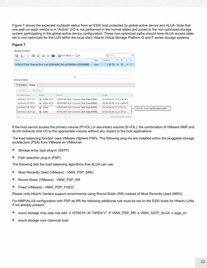
Figure 7 shows the expected multipath status from an ESXi host protected by global-active device and ALUA. Note that one path on each vmhba is in "Active" (I/O is not performed in the normal state) and zoned to the non-optimized storage system participating in the global-active device configuration. These non-optimized paths should have ALUA access state set to non-optimized for the LUN within the local site's Hitachi Virtual Storage Platform G and F series storage systems.
Figure 7
If the host cannot access the primary volume (P-VOL) or secondary volume (S-VOL), the combination of VMware NMP and ALUA redirects host I/O to the appropriate volume without any impact to the host applications.
The load balancing function uses VMware vSphere PSPs. The following plug-ins are installed within the pluggable storage architecture (PSA) from VMware on VMKernel:
Storage array type plug-in (SATP)
Path selection plug-in (PSP)
The following lists the load balancing algorithms that ALUA can use:
Most Recently Used (VMware) : VMW_PSP_MRU
Round Robin (VMware) : VMW_PSP_RR
Fixed (VMware) : VMW_PSP_FIXED
Please note Hitachi Vantara support recommends using Round Robin (RR) instead of Most Recently Used (MRU).
For NMP/ALUA configuration with PSP as RR the following additional rule must be set on the ESXi hosts for Hitachi LUNs if not already present:
esxcli storage nmp satp rule add -V HITACHI -M "OPEN-V" -P VMW_PSP_RR -s VMW_SATP_ALUA -c tpgs_on
esxcli storage core claimrule load
23

24
Figure 8 shows a status of Path Selection Policy for global-active device volumes.
Figure 8
RAID and Dynamic Pool ConfigurationThe storage implementation for this solution uses a RAID 10 (2D+2D) configuration for the management pool and RAID 10 (2D+2D) or RAID 6 (6D+2P) configuration for the compute pool. The management pool is used to store the infrastructure virtual machines (VMs). These VMs provide the management layer for UCP CI appliance. Both RAID 10 and RAID 6 offer the best performance and redundancy for its intended usage. While using dynamic provisioning pools provides the best performance for VMware virtual machines file placements, it also allows ease of scaling by adding additional disk resource to gain performance or capacity without interrupting VMware ESXi Server operations.
RAID Configuration
Create a parity group as follows:
One parity group for RAID 10 (2D+2D), using four disks for UCP Management Pool.
One parity group for RAID 6 (6D+2P), using eight disks for UCP Compute Pool.
Dynamic pools can be expanded by adding additional parity groups to support additional workloads and virtual machines.
Pool Configuration
This reference architecture requires Hitachi Dynamic Provisioning for use on a global-active device to simplify management of the storage.
This solution's compute pool uses a dynamic provisioning pool comprised of a single RAID group with eight drives in a RAID 6 (6D+2P) configuration for each storage system. Using a RAID 6 configuration lowers the risk of data loss or pool failure, which is a primary concern for virtual machines protected in a stretch cluster environment.
Figure 9 shows the dynamic provisioning pool configuration on each storage system. The Dynamic Provisioning pools configuration on Site 2 is identical to the Site 1 configuration. The LUNs on Site 2 are identical in size to their respective protected LUNs, as required for maintaining the P-VOL and S-VOL relationship. Both the P-VOL and S-VOL LUNs are presented to all ESXi compute hosts through local and cross-site paths.
24

25
Figure 9
Provision one command device LUN in each site:
A command device is a dedicated logical volume on the storage system that functions as the interface to the storage system from a host.
Provision a 48 MB LUN, the smallest LUN that can be created, on both sites.
These LUNs are converted to command devices and presented to the pair management server.
Provision VMFS LUNs in the implementation of this environment:
Datastore for storing management virtual machines (non-replicated)
Datastore for storing compute virtual machines by leveraging global-active device
Physical Network ArchitectureCisco Nexus 3000 and 9000 provide Ethernet switching and communications between the Hitachi Advanced Server DSxx0 series servers, Hitachi VSP G and F series storage system, and VMware vSphere and vCenter Server Appliance.
Figure 10 shows a multi-rack network topology using Spine-Leaf design. With Spine-Leaf configurations, all devices are exactly the same number of segments away and contain a predictable and consistent amount of delay or latency for traveling information. This is possible because of the new topology design that has only two layers, the Spine layer and Leaf layer. The Leaf layer consists of access switches that connect to devices such as servers, firewalls, and load balancers. The Spine layer is the backbone of the network, where every Leaf switch is interconnected with each and every Spine switch.
25

26
Two Cisco 93180LC-EX spine switches provide 40 / 100 GbE connections to leaf switches. These 93180LC-EX switches are uplinked to core switches using 40 /100 GbE connections. Two Cisco 93180YC-EX leaf switches provide 10/25 GbE connections for server communications. One Cisco 3048 provides 1 GbE connections for management.
Figure 10
Note — The VMware vSphere Metro Storage Cluster environment clusters physical data centers within metro distance. A stretched layer 2 network is required between Site 1 and Site 2.
Virtual Network ArchitectureUCP CI systems support vSphere Standard Switches or vSphere Distributed Switches (vDS) for its virtual network configuration.
The standard switch is the base network virtualization switch. Most of the features are required to connect the virtual machines to the virtual host and physical NIC cards so that they all have network connectivity. The vDS requires an enterprise plus license. vDS acts as a single switch across all associated hosts in the datacenter to provide centralized provisioning, administration, and monitoring of virtual networks.
26

27
Solution ValidationFor testing purposes, the following test cases were run to validate the VMware vSphere Metro Storage Cluster reference architecture.
VMware feature test cases
Use vSphere vMotion or VMware Distributed Resource Scheduler to migrate virtual machines between Site 1 and Site 2
Use vSphere High Availability to failover virtual machines from Site 1 to Site 2
Failure test cases
Single storage path failure
Site 1 storage failure
All active paths to local storage system fail for a single host on either site
All paths down occurs in any ESXi host in the cluster
Quorum disk failure
Storage replication link failure
Wide area network storage connection failure
Site 1 failure/Site 2 failure
Recovering from storage failover (failback)
Table 3 outlines the tested and supported failure scenarios when using a Hitachi Storage Cluster for VMware vSphere with Hitachi Virtual Storage Platform G and F series storage systems and global-active device. This table below documents the uniform host access-based configuration. Non-uniform behaves the same expect where it leverages the site failure scenario for local storage failure.
TABLE 3. TESTED SCENARIOS
Scenario Global-active Device/Multipath (ALUA) Behavior
Observed VMware behavior
Using vSphere vMotion or VMware Distributed Resource Scheduler to migrate virtual machines between Site 1 and Site 2
No impact Virtual machine migrates to Site 2 hosts and I/O is directed to the local storage S-VOL on Site 2.
Using vSphere High Availability to failover virtual machines between Site 1 and Site 2.
No impact Virtual machine fails over to Site 2 hosts and I/O is directed to the local storage S-VOL on Site 2.
An active path in a single host fails.
Host I/O is redirected to an available active path via PSP
Another active path is used
No disruption to virtual machines
27

28TABLE 3. TESTED SCENARIOS (CONTINUED)
Site 1 storage system fails Storage failover
Global-active device verifies data integrity with the quorum disk before failover.
Global-active device splits the pair replication and S-VOL is converted to SSWS (S Local).
Host I/O is redirected via ALUA SATP to the standby S-VOL paths on the Site 2 storage system.
Active paths to P-VOL are reported dead
Standby paths to S-VOL become active
No disruption to virtual machines
All active paths to the local storage system fail for any ESXi host in the cluster.
Host I/O in each Site is redirected to available standby (ALUA state is "non-optimized") paths on the remote storage system via PSP.
Active paths to the local storage system are reported dead
Standby paths to the remote storage system become active
No disruption to virtual machines
All paths down (APD) occurs in any ESXi host in the cluster.
Storage failover does not occur.
Virtual machine is automatically failed over to another host in a high availability cluster by part of vSphere High Availability called virtual machine component protection (VMCP).
Quorum disk fails or all paths to quorum disk removed
Replication between PVOL and S-VOL continues and the P-VOL and S-VOL stays in pair state.
No disruption to virtual machines
Scenario Global-active Device/Multipath (ALUA) Behavior
Observed VMware behavior
28

29
Storage replication link failure Global-active device verifies the data integrity with quorum disk and determine the one of two (P-VOL and S-VOL) as local I/O mode (the other is as block I/O. The decision depends on the state of both volumes which is notified and written to quorum disk.
When the volume (for example, P-VOL) is chosen to continue to perform host I/O, all access to the other (S-VOL) is blocked and is failed over to P-VOL (P Local).
Host I/O in Site 2 is redirected to standby paths to P-VOL on remote storage in Site 1.
Active paths to S-VOL are reported dead
Standby paths to P-VOL become active
No disruption to virtual machines
WAN storage connection failure Storage failover occurs, same as "storage replication link failure" except path behavior.
The path failover doesn't occur.
When P-VOL is chosen to convert to P-Local, host I/O in Site 1 is still continued to process using path to local storage in Site 1. Because local site access remains active, virtual machines on Site 1 can access the local P-VOL.
Site 1: After storage failover, P-VOL will process host I/O for Site 1 hosts because local site access remains active. Virtual machines on Site 1 can access the local P-VOL.
Virtual machines on Site 2 hosts are unable to access their virtual disks on Site 1. Virtual machine is automatically failed over to another host in a high availability cluster by part of vSphere High Availability called virtual machine component protection (VMCP).
TABLE 3. TESTED SCENARIOS (CONTINUED)
Scenario Global-active Device/Multipath (ALUA) Behavior
Observed VMware behavior
29

30
VMware Feature Test CasesThese are the VMware feature test cases.
Using VMware vSphere vMotion or Distributed Resource Scheduler to Migrate Virtual Machines Between Site 1 and Site 2
Since all ESXi hosts on both sites can access both the P-VOL and the S-VOL on the storage system, VMware vSphere vMotion and VMware Distributed Resource Scheduler are capable of migrating virtual machines between hosts at different sites.
Site 1 failure Same as “Site 1 storage system failure” in terms of storage behavior.
Storage replication between P-VOL and S-VOL stops (pairsplit) and storage failover occurs. S-VOL is converted to SSWS(S Local).
vSphere High Availability fails over virtual machines to available Site 2 hosts.
Site 2 failure Storage replication between P-VOL and S-VOL stops (pair split) and storage failover occurs.
P-VOL is converted to PSUE (P Local).
vSphere High Availability fails over virtual machines to available Site 1 hosts.
TABLE 3. TESTED SCENARIOS (CONTINUED)
Scenario Global-active Device/Multipath (ALUA) Behavior
Observed VMware behavior
30
31
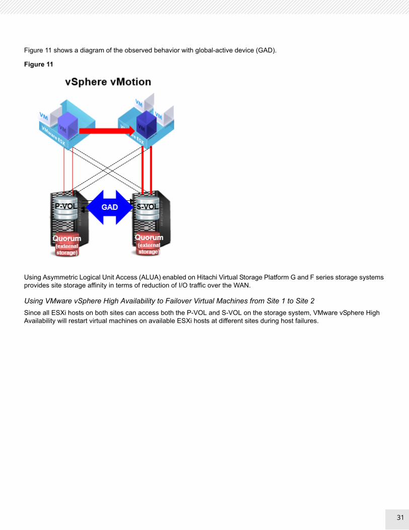
Figure 11 shows a diagram of the observed behavior with global-active device (GAD).
Figure 11
Using Asymmetric Logical Unit Access (ALUA) enabled on Hitachi Virtual Storage Platform G and F series storage systems provides site storage affinity in terms of reduction of I/O traffic over the WAN.
Using VMware vSphere High Availability to Failover Virtual Machines from Site 1 to Site 2
Since all ESXi hosts on both sites can access both the P-VOL and S-VOL on the storage system, VMware vSphere High Availability will restart virtual machines on available ESXi hosts at different sites during host failures.
31

32
Figure 12 below shows a diagram of the observed behavior with global-active device (GAD).
Figure 12
If storage host groups and virtual machine Distributed Resource Scheduler groups are configured with affinity rules to keep virtual machines on Site 1 hosts, VMware vSphere High Availability may restart virtual machines on Site 2 hosts but will then use vMotion to move the virtual machines to Site 1 hosts, if available.
Failure Test CasesThe following failure test cases are simulated by physically removing cables, taking Fibre Channel ports off-line, or removing zones from the Fibre Channel fabric.
Single Path Failure
When a single active path from an ESXi host to local storage in Site 1 fails, host I/O is redirected to an available active path via the ALUA type plug-in (SATP) and path selection plug-in (PSP).
32

33
Figure 13 shows a diagram of the failure scenario with global-active device (GAD).
Figure 13
When the path is restored, it automatically becomes available and active for use by the ESXi host.
Site 1 Storage Failure
When the Site 1 storage system fails, the following happens:
Global-active device verifies data integrity with the quorum disk before failover.
Global-active device splits pair replication and storage failover occurs. S-VOL remains write enabled and is converted to SSWS (S Local) status.
All ESXi host I/O is redirected through the standby path to the S-VOL hosted on the Site 2 storage system.
The following is observed in the VMware infrastructure:
Active paths to the P-VOL on Site 1 storage system are reported dead.
Standby paths to the S-VOL on Site 2 storage system become active.
No disruption is seen on the virtual machine.
33

34
Figure 14 shows a diagram of the failure scenario with global-active device (GAD).
Figure 14
To restore the Metro Storage Cluster to its original state, see Recovering from Storage Failover (Failback).
All Active Paths to Local Storage System Fail for a Single Host on Either Site
When a single ESXi host (located in Site 1 or Site 2) in the cluster loses all active paths to local storage system, the host I/O is redirected to available standby (non-optimized) paths to the remote storage system.
34

35
Figure 15 shows a diagram of the failure scenario with global-active device (GAD).
Figure 15
When the path is restored, it automatically becomes available and active for use by the ESXi host.
All Paths Down Occurs in any ESXi host in the Cluster
When a single ESXi host (located in Site 1 or Site 2) in the cluster loses all paths to local storage and remote storage systems, the host I/O is not able to continue to process, unless the virtual machines are restarted on other available hosts.
Note — VMware defines this as an all paths down condition. VMware vSphere 6.0 and later have a powerful new feature as part of vSphere High Availability called virtual machine component protection (VMCP). VMCP protects virtual machines from storage related events, specifically permanent device loss (PDL) and all paths down (APD) incidents. In cases of PDL or ADP, a virtual machine is automatically fails over to another host in a high availability cluster by vSphere High Availability.
35

36
Figure 16 shows a diagram of the failure scenario with global-active device (GAD).
Figure 16
Quorum Disk Failure
Even if the quorum disk fails or all paths to the quorum disk are removed, replication between P-VOL and S-VOL will continue and the PVOL and S-VOL will remain in pair state.
36

37
Figure 17 shows a diagram of the failure scenario with global-active device (GAD).
Figure 17
Storage Replication Link Failure
When the storage replication link fails, the following occurs:
Replication between the P-VOL on Site 1 storage system and the S-VOL on Site 2 storage system stops.
Both P-VOL and S-VOL enter PSUE (pair split) state. Global-active device verifies the data integrity with quorum disk and determines one of the volumes (P-VOL or S-VOL) as Local I/O mode (the other is marked as Block I/O mode) to continue to perform host I/O.
The decision depends on the state of the quorum disk which stores both the P-VOL and S-VOL state and updates it when communication interruption occurs between the P-VOL and S-VOL.
When the P-VOL is chosen to continue to perform host I/O, all access to S-VOL is blocked (S Block) and it is failed over to P-VOL (P Local).
All host I/O in Site 2 is redirected to standby paths to P-VOL on remote storage in Site 1.
37

38
Figure 18 shows a diagram of the failure scenario with global-active device (GAD).
Figure 18
Once replication link issues are resolved, resume replication through the Hitachi Command Suite graphical user interface, or use command control interface.
Wide Area Network Storage Connection Failure
Note — Permanent device loss default behavior has changed with the release of VMware vSphere 6.0. For vSphere 6.x hosts, advanced setting is no longer required to be changed from the default configuration to properly recover the devices marked as PDL. For more information, see VMware Knowledge Base article 2059622.
38

39
During a wide area network storage connection failure, where links for replication and access across sites fail but links to the local site and layer 2 network connectivity remain active, the same behavior as the storage replication link path failure scenario takes place and the following occurs:
When P-VOL is chosen to continue to perform host I/O, all access to S-VOL is blocked (S Block) and is failed over to P-VOL (P Local).
When global-active device fails over to P-VOL, the ESXi hosts on Site 2 cannot continue to process host I/O due to all paths to P-VOL on remote storage in Site 1 marked as dead.
It receives PDL, and virtual machines are automatically failed over to another host in a high availability cluster by part of vSphere High Availability called virtual machine component protection (VMCP).
On Site 1, after storage failover, P-VOL will process host I/O for Site 1 hosts because local site access remains active. Virtual machines on Site 1 can access the local P-VOL.
Figure 19 shows a diagram of the failure scenario with global-active device (GAD).
Figure 19
39

40
Note — This scenario describes a storage connection-only failure across sites. WAN failures involving both storage and network connections will trigger vSphere High Availability to automatically restart virtual machines on Site 1 hosts.
To restore the metro cluster to its original state, see Recovering from Storage Failover (Failback).
Site 1 Failure
When Site 1 fails, the following occurs:
Same as Site 1 Storage Failure regarding storage behavior.
Storage replication between P-VOL and S-VOL stops (pair split), and storage failover occurs. S-VOL is converted to SSWS (S Local).
The following is observed in the VMware infrastructure:
All Site 1 ESXi hosts fail and vSphere High Availability restarts virtual machines on Site 2 ESXi hosts.
Active paths to the P-VOL on Site 1 storage system are reported dead.
40

41
Figure 20 shows a diagram of the failure scenario with global-active device (GAD).
Figure 20
To restore the metro cluster to its original state, see Recovering from Storage Failover (Failback).
Site 2 Failure
When Site 2 fails, the following occurs:
Storage replication between P-VOL and S-VOL stops (pair split), and storage failover occurs. P-VOL is converted to PSUE (P Local).
The following is observed in the VMware infrastructure:
All Site 2 ESXi hosts fail and vSphere High Availability restarts virtual machines on Site 1 ESXi hosts.
Active paths to the S-VOL on Site 2 storage system are reported dead.
41

42
Figure 21 shows a diagram of the failure scenario with global-active device (GAD).
Figure 21
Recovering from Storage Failover (Failback)The following assumes that global-active device has triggered a storage failover to the S-VOL on Site 2. After Site 1 storage has been restored and is ready to serve production data, the following steps are required for restoring the metro storage cluster to its original state:
The recovery procedure is divided into two procedures depending on if the global-active device is in a P-Local or S-Local state.
The following is the recovery procedure from S-Local after fixing the Site 1 failure:
1. Re-establish replication of S-VOL data to P-VOL.
2. Execute takeover-recovery (resync) of the GAD pair.
3. Check that pair status is PAIR and swap the copy direction of the GAD pair.
4. Restart the ESXi hosts in Site 1.
The combination of VMware NMP and ALUA automatically fails paths back to P-VOL on local storage in each site.
42

43
Figure 22 shows a diagram of the recovery scenario with global-active device (GAD).
Figure 22
The following is the recovery procedure from P-Local after fixing the Site 2 failure:
1. Execute a re-sync of the GAD pair.
2. Restart the ESXi hosts in Site 2.
The combination of VMware NMP and ALUA automatically fails paths back to P-VOL on local storage in each site.
43
44
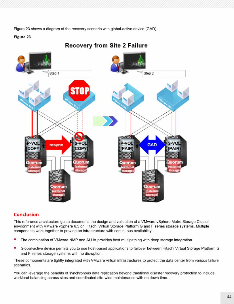
Figure 23 shows a diagram of the recovery scenario with global-active device (GAD).
Figure 23
ConclusionThis reference architecture guide documents the design and validation of a VMware vSphere Metro Storage Cluster environment with VMware vSphere 6.5 on Hitachi Virtual Storage Platform G and F series storage systems. Multiple components work together to provide an infrastructure with continuous availability:
The combination of VMware NMP and ALUA provides host multipathing with deep storage integration.
Global-active device permits you to use host-based applications to failover between Hitachi Virtual Storage Platform G and F series storage systems with no disruption.
These components are tightly integrated with VMware virtual infrastructures to protect the data center from various failure scenarios.
You can leverage the benefits of synchronous data replication beyond traditional disaster recovery protection to include workload balancing across sites and coordinated site-wide maintenance with no down time.
44

1
Corporate Headquarters2845 Lafayette StreetSanta Clara, CA 96050-2639 USAHitachiVantara.com | community.HitachiVantara.com
Contact InformationUSA: 1-8000446-0744Global: 1-858-547-4526HitachiVantara.com/contact
Hitachi Vantara
© Hitachi Vantara Corporation, 2018. All rights reserved. HITACHI is a trademark or registered trademark of Hitachi, Ltd. All other trademarks, service marks, and company names are properties of their respective owners
Notice: This document is for informational purposes only, and does not set forth any warranty, expressed or implied, concerning any equipment or service offered or to be offered by Hitachi Vantara Corporation.
MK-SL-120-00, November 2018