hitachi corrective measures section 4 - california … · (usepa) method 6010b and 7470/7471 and...
TRANSCRIPT
Attachment I
Material Safety Data Sheet for Shell Sol 140


APPENDIX A
ATTACHMENTS TO THE SOIL INSPECTION/SAMPLING PLAN
ATTACHMENT I SOIL INSPECTION/SAMPLING PLAN
FOR ROADS/PARKING LOTS
Original: August 22, 2005 Revision 1: January 31, 2006
I-1
ATTACHMENT I SOIL INSPECTION/SAMPLING PLAN
FOR ROADS/PARKING LOTS TABLE OF CONTENTS I.1 Overview I.2 History I.3 Project Planning I.4 Implementation of Soil Sampling I.5 Data Management and Reporting I.6 Project Schedule I.7 References TABLES I.1 Sample Identification Table FIGURES I.1 Proposed NOA Sampling Locations
I-2
ACRONYMS CARB California Air Resources Board CCR Current Conditions Report COC Chain-of-Custody DJPA David J. Powers & Associates DTSC Department of Toxic Substances Control EIR Environmental Impact Report GPA General Plan Amendment GST Global Storage Technologies HHRA Human Health Risk Assessment IDW Investigation Derived Waste NOA Naturally-Occurring Asbestos PD Planned Development STL Severn Trent Laboratories USEPA United States Environmental Protection Agency

I-3
ATTACHMENT I SOIL INSPECTION/SAMPLING PLAN
FOR ROADS/PARKING LOTS I.1 Overview Recently, David J. Powers & Associates (DJPA) prepared an Environmental Impact Report (EIR) for the proposed General Plan Amendment (GPA) and Planned Development (PD) Zoning on the approximately 332-acre Hitachi Global Storage Technologies, Inc. (Hitachi GST) property located at 5600 Cottle Road, San Jose, California (“the Site”). The City of San Jose Planning Commission certified the Final EIR on June 6, 2005 (City of San Jose 2005a, 2005b). As part of the EIR, ENVIRON International Corporation (ENVIRON) prepared a screening human health risk assessment (Screening HHRA) to evaluate the potential impacts on human health for Parcels O-1 through O-5, termed the Redevelopment Area (approximately 131 acres). In addition, ENVIRON prepared a Draft Current Conditions Report (CCR) (ENVIRON 2005) for these same parcels. The purpose of this Soil Inspection/Sampling Plan is to address the following areas identified in the Screening HHRA/Draft CCR as needing additional evaluation/investigation:
Confirmatory sampling for naturally-occurring asbestos (NOA) in fill beneath roadways and parking lots in the Redevelopment Area is recommended assuming these areas are to be disturbed and/or relocated as part of Site redevelopment activities. As the potential source of any NOA would have been imported fill, only areas beneath parking areas and roadways are being recommended for sampling.
Limited sampling for metals in fill beneath the roadways and parking lots in the
Redevelopment Area is recommended for fill material that will remain on-site for reuse. Sample analysis for metals will commence after the results of the asbestos samples have been processed and the fill material has been characterized for proper use or disposal.
It is also recommended that an environmental engineer inspect all building foundations after demolition. If it is suspected that fill materials containing NOA were used beneath a building, then this area will also be sampled according to this plan. In addition to the Redevelopment Area, Hitachi GST will be transferring ownership of Endicott Boulevard/Tucson Way to the City of San Jose. This road, which borders the Site to the north, is also being evaluated/investigated as part of this Soil Inspection/Sampling Plan.

I-4
The results of this Soil Inspection/Sampling Plan will be used to determine if any mitigation/remediation measures are needed at the Site for NOA in roadbase materials. I.2 History
During development of the Site, construction-grade fill material, which contained NOA in the form of serpentine rock, from a local quarry was used as fill beneath parking lots and roadways. The serpentine-rock-containing fill was identified during soil excavation activities related to the Site cleanup in the early 1980s. Hitachi GST personnel reported that Hitachi GST’s policy has been that additional fill containing NOA is removed only during construction or demolition activities that may disturb the NOA-containing fill. Hitachi GST personnel were unable to provide an estimate of how much NOA-containing fill, if any, remains on the Site. Confirmatory sampling for asbestos beneath parking areas and along roadways is being recommended for the Redevelopment Area (and Endicott Boulevard/Tucson Way) assuming the fill beneath the roadways and/or parking lots is to be disturbed and/or relocated as part of Site redevelopment. Pending the results of the asbestos sampling, ENVIRON recommends limited sampling for metals of the fill material that will remain on-site. I.3 Project Planning Fill beneath all roads and parking areas in the Redevelopment Area and Endicott Boulevard/Tucson Way will be sampled according to the Inspection/Sampling Plan presented in Section I.4 below. As the areas are currently accessible (it is anticipated that the driller will core through the asphalt), the sampling can begin once this Soil Inspection/Sampling Plan is approved. In addition, an environmental engineer will be present on-site during building demolition to inspect any fill materials beneath the building foundation. If the presence of NOA is suspected, then the fill beneath the building foundation will also be sampled according to the sampling plan. As this requires the demolition of the currently existing buildings, the inspections are planned to proceed according to the following tentative demolition plan:
Year Building mid to late 2006 B010, B026, B012, B028 early 2007 B018, B051
Buildings B009 and B011 will remain intact (historical preservation). There are no current plans to sample beneath any buildings to remain on the Redevelopment Area.

I-5
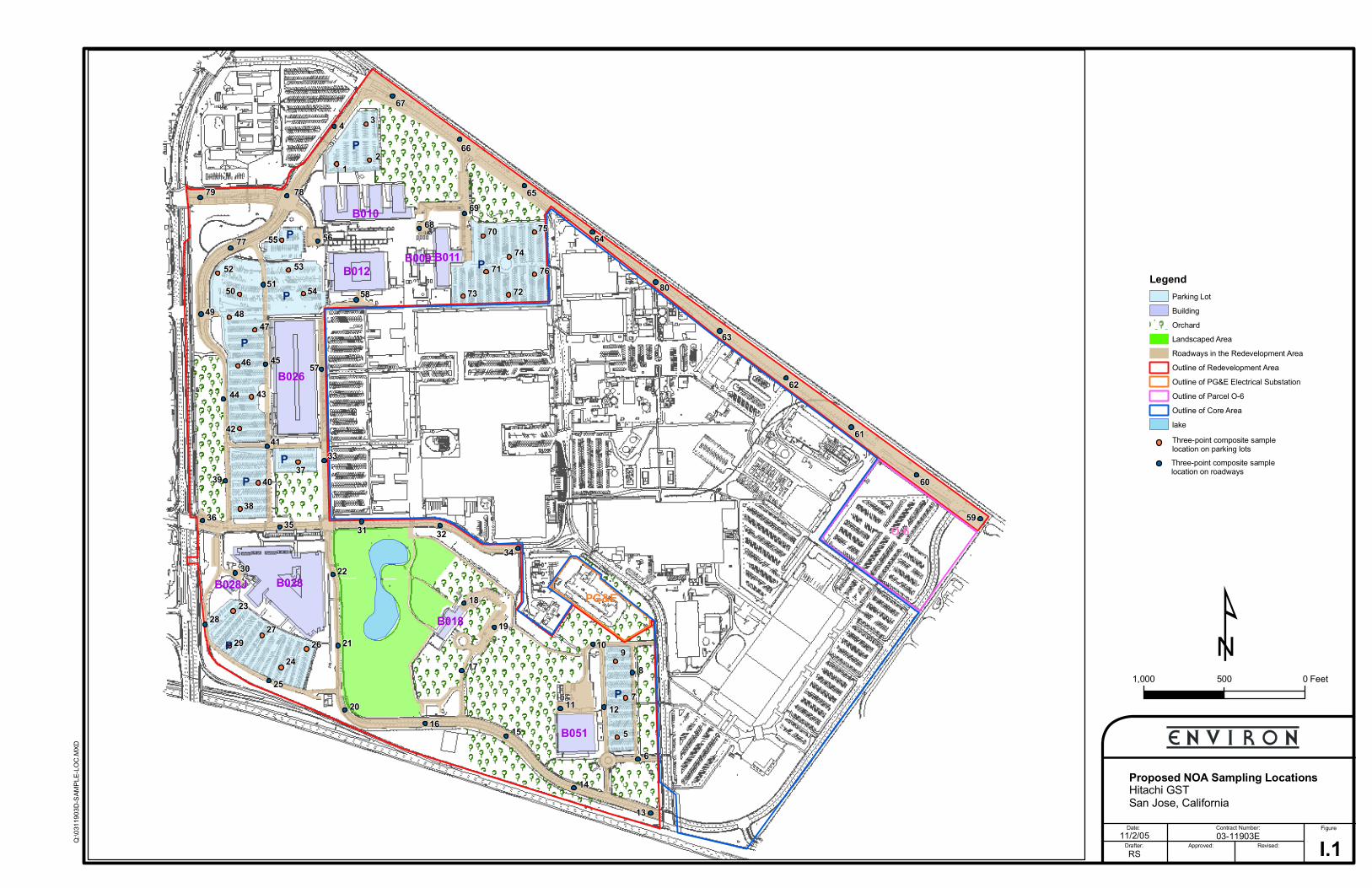
I.4 Implementation of Soil Sampling All roadways and parking areas in the Redevelopment Area are highlighted on Figure I.1. In addition, Endicott Boulevard/Tucson Way has been highlighted. Prior to initiating any field activities, ENVIRON will conduct a survey of underground utilities at proposed sampling locations, arrange for drilling and analytical laboratory subcontractors, and update the Site-specific health and safety plan. Prior to collection of each sample, a driller will core through the asphalt pavement. ENVIRON personnel will collect a sample of the aggregate fill using hand trowels. Following collection of the aggregate fill sample, the hole will be grouted and patched with asphalt. Three samples per acre will be collected from the aggregate fill beneath the asphalt parking lots for analysis of asbestos. The samples will be composited by the laboratory such that one, three-point composite sample will be analyzed per acre of parking lot. Similarly, one three-point composite sample will be analyzed for every 500 feet of roadway. It is anticipated that a total of approximately 85, three-point composite samples will be analyzed for asbestos from the aggregate fill beneath the roadways and parking lots. The proposed three-point composite sampling locations are summarized on Table I.1 and are also depicted on Figure I.1. Fill sample collection and analytical methods will be in accordance with the Department of Toxic Substances Control (DTSC) Interim Guidance: Naturally Occurring Asbestos at School Sites (Draft)(2004). As required by the guidance, the soil samples will be prepared and analyzed using California Air Resources Board (CARB) Method 435 to estimate the percent of asbestos at an accuracy of 0.25%. The thickness of the aggregate fill will be measured at each sample location and recorded in the field sampling log form. The fill samples collected will be submitted to Forensic Analytical along with chain-of-custody (COC) documentation. The samples will be analyzed on a 10-day turnaround time, unless otherwise agreed upon with Hitachi GST and the laboratory. Once the fill has been characterized, fill samples will be collected and sampled for metals at a minimum of 10 randomly selected locations. The grab samples will be collected in glass jars. Secondary fill samples will be submitted to Severn Trent Laboratories (STL), a California State-certified analytical laboratory. If STL is not available for the sample analyses, another California State-certified analytical laboratory will be retained. All samples will be submitted under COC protocol for analysis for CAM 17 Metals by the United States Environmental Protection Agency (USEPA) Method 6010B and 7470/7471 and for pH by USEPA Method 9045. The samples will

I-6
be analyzed on a 10-day turnaround time, unless otherwise agreed upon with Hitachi GST and the laboratory. At the end of each sampling day, sample information will be written on COC forms. Information entered onto the form includes the sample identification number, sample matrix, date of sample collection, location of sample, and requested analyses. Each COC form will consist of three carbon copy sheets, two of which will be placed in the appropriate sample shipping cooler for laboratory use, with the third sheet being retained by the Field Manager. COC forms will be placed in adhesive plastic windows and affixed to the inside of the shipping cooler lid. Coolers will then be closed, sealed with duct tape, and custody seals affixed to each cooler to enable detection of tampering. Investigation derived waste (IDW) will be collected in appropriate containers that will be labeled and sealed following completion of field activities. Management and disposal of IDW will be the responsibility of Hitachi GST. ENVIRON will provide Hitachi GST with the relevant analytical results to assist Hitachi GST with appropriate management and disposal of IDW. I.5 Data Management and Reporting Upon receipt of the analytical results, ENVIRON will prepare a summary table of the data and compare the results to the DTSC action level for NOA at school sites of 0.25% (DTSC 2004). Based on this evaluation, a recommendation will be made for no further action, further investigation, and/or remediation. The results of this evaluation will be summarized in a short letter report (plus tables and figures) to be submitted to DTSC. If NOA is detected and if the fill material is disturbed, a Health and Safety Plan, Air Monitoring Plan, and Asbestos Dust Mitigation Plan will be prepared consistent with DTSC and CARB guidelines. If the fill material is transported off-site, a Transportation Plan will also be prepared. I.6 Project Schedule It is anticipated that the sampling beneath roadways and parking lots will take approximately four weeks (including field and analytical) after authorization to proceed. The inspection of building foundations will proceed according to the building demolition schedule. I.7 References City of San Jose, California. 2005a. Draft Environmental Impact Report. Hitachi Campus and
Mixed-Use Transit Village Project. General Plan Amendment (GP04-02-01) and Planned Development Rezoning (PDC04-031). SCH#2004072110. Volume I through V. Approved as Final: June 6.

I-7
City of San Jose, California. 2005b. First Amendment to the Draft Environmental Impact
Report. Hitachi Campus and Mixed-Use Transit Village Project. General Plan Amendment (GP04-02-01) and Planned Development Rezoning (PDC04-031). SCH#2004072110. Volume I through V. Approved as Final: June 6.
Department of Toxic Substance Control (DTCS). 2004. Interim Guidance: Naturally Occurring
Asbestos (NOA) at School Sites (Draft). July. ENVIRON International Corporation (ENVIRON). 2005. Draft Current Conditions Report,
Hitachi Global Technologies, Inc., Redevelopment Area and Endicott Boulevard/Tucson Way, 5600 Cottle Road, San Jose, California. July.
Y:\Hitachi\O-1_to_O-5_Planning\Attach I - Roads-Parking Lots\Revised Attach I 1-31-06

TABLES
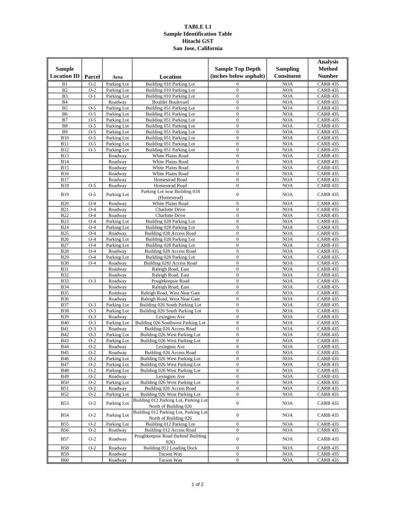
TABLE I.1Sample Identification Table
Hitachi GSTSan Jose, California
Sample Location ID Parcel Area Location
Sample Top Depth (inches below asphalt)
Sampling Consituent
AnalysisMethod Number
B1 O-2 Parking Lot Building 010 Parking Lot 0 NOA CARB 435B2 O-2 Parking Lot Building 010 Parking Lot 0 NOA CARB 435B3 O-1 Parking Lot Building 010 Parking Lot 0 NOA CARB 435B4 Roadway Boulder Boulevard 0 NOA CARB 435B5 O-5 Parking Lot Building 051 Parking Lot 0 NOA CARB 435B6 O-5 Parking Lot Building 051 Parking Lot 0 NOA CARB 435B7 O-5 Parking Lot Building 051 Parking Lot 0 NOA CARB 435B8 O-5 Parking Lot Building 051 Parking Lot 0 NOA CARB 435B9 O-5 Parking Lot Building 051 Parking Lot 0 NOA CARB 435
B10 O-5 Parking Lot Building 051 Parking Lot 0 NOA CARB 435B11 O-5 Parking Lot Building 051 Parking Lot 0 NOA CARB 435B12 O-5 Parking Lot Building 051 Parking Lot 0 NOA CARB 435B13 Roadway White Plains Road 0 NOA CARB 435B14 Roadway White Plains Road 0 NOA CARB 435B15 Roadway White Plains Road 0 NOA CARB 435B16 Roadway White Plains Road 0 NOA CARB 435B17 Roadway Homestead Road 0 NOA CARB 435B18 O-5 Roadway Homestead Road 0 NOA CARB 435
B19 O-5 Parking LotParking Lot near Building 018
(Homestead)0 NOA CARB 435
B20 O-4 Roadway White Plains Road 0 NOA CARB 435B21 O-4 Roadway Charlotte Drive 0 NOA CARB 435B22 O-4 Roadway Charlotte Drive 0 NOA CARB 435B23 O-4 Parking Lot Building 028 Parking Lot 0 NOA CARB 435B24 O-4 Parking Lot Building 028 Parking Lot 0 NOA CARB 435B25 O-4 Roadway Building 028 Access Road 0 NOA CARB 435B26 O-4 Parking Lot Building 028 Parking Lot 0 NOA CARB 435B27 O-4 Parking Lot Building 028 Parking Lot 0 NOA CARB 435B28 O-4 Roadway Building 028 Access Road 0 NOA CARB 435B29 O-4 Parking Lot Building 028 Parking Lot 0 NOA CARB 435B30 O-4 Roadway Building 028J Access Road 0 NOA CARB 435B31 Roadway Raleigh Road, East 0 NOA CARB 435B32 Roadway Raleigh Road, East 0 NOA CARB 435B33 O-3 Roadway Poughkeepsie Road 0 NOA CARB 435B34 Roadway Raleigh Road, East 0 NOA CARB 435B35 Roadway Raleigh Road, West Near Gate 0 NOA CARB 435B36 Roadway Raleigh Road, West Near Gate 0 NOA CARB 435B37 O-3 Parking Lot Building 026 South Parking Lot 0 NOA CARB 435B38 O-3 Parking Lot Building 026 South Parking Lot 0 NOA CARB 435B39 O-3 Roadway Lexington Ave 0 NOA CARB 435B40 O-3 Parking Lot Building 026 Southwest Parking Lot 0 NOA CARB 435B41 O-3 Roadway Building 026 Access Road 0 NOA CARB 435B42 O-3 Parking Lot Building 026 West Parking Lot 0 NOA CARB 435B43 O-2 Parking Lot Building 026 West Parking Lot 0 NOA CARB 435B44 O-2 Roadway Lexington Ave 0 NOA CARB 435B45 O-2 Roadway Building 026 Access Road 0 NOA CARB 435B46 O-2 Parking Lot Building 026 West Parking Lot 0 NOA CARB 435B47 O-2 Parking Lot Building 026 West Parking Lot 0 NOA CARB 435B48 O-2 Parking Lot Building 026 West Parking Lot 0 NOA CARB 435B49 O-2 Roadway Lexington Ave 0 NOA CARB 435B50 O-2 Parking Lot Building 026 West Parking Lot 0 NOA CARB 435B51 O-2 Roadway Building 026 Access Road 0 NOA CARB 435B52 O-2 Parking Lot Building 026 West Parking Lot 0 NOA CARB 435
B53 O-2 Parking LotBuilding 012 Parking Lot, Parking Lot
North of Building 0260 NOA CARB 435
B54 O-2 Parking LotBuilding 012 Parking Lot, Parking Lot
North of Building 0260 NOA CARB 435
B55 O-2 Parking Lot Building 012 Parking Lot 0 NOA CARB 435B56 O-2 Roadway Building 012 Access Road 0 NOA CARB 435
B57 O-2 RoadwayPoughkeepsie Road (behind Building
026)0 NOA CARB 435
B58 O-2 Roadway Building 012 Loading Dock 0 NOA CARB 435B59 Roadway Tucson Way 0 NOA CARB 435B60 Roadway Tucson Way 0 NOA CARB 435
1 of 2

TABLE I.1Sample Identification Table
Hitachi GSTSan Jose, California
Sample Location ID Parcel Area Location
Sample Top Depth (inches below asphalt)
Sampling Consituent
AnalysisMethod Number
B61 Roadway Tucson Way 0 NOA CARB 435B62 Roadway Tucson Way 0 NOA CARB 435B63 Roadway Tucson Way 0 NOA CARB 435B64 Roadway Tucson Way 0 NOA CARB 435B65 Roadway Endicott Boulevard 0 NOA CARB 435B66 Roadway Endicott Boulevard 0 NOA CARB 435B67 Roadway Endicott Boulevard 0 NOA CARB 435B68 O-1 Roadway Building 011/009 Access Road 0 NOA CARB 435B69 O-1 Roadway Building 011/009 Access Road 0 NOA CARB 435B70 O-1 Parking Lot Building 005 Parking Lot 0 NOA CARB 435B71 O-1 Parking Lot Building 005 Parking Lot 0 NOA CARB 435B72 O-1 Parking Lot Building 005 Parking Lot 0 NOA CARB 435B73 O-1 Parking Lot Building 005 Parking Lot 0 NOA CARB 435B74 O-1 Parking Lot Building 005 Parking Lot 0 NOA CARB 435B75 O-1 Parking Lot Building 005 Parking Lot 0 NOA CARB 435B76 O-1 Parking Lot Building 005 Parking Lot 0 NOA CARB 435B77 O-2 Roadway Lexington Ave 0 NOA CARB 435
B78 O-2 RoadwayPoughkeepsie Road (near main
entrance gate)0 NOA CARB 435
B79 O-2 RoadwayPoughkeepsie Road (near main
entrance gate)0 NOA CARB 435
B80 Roadway Tucson Way 0 NOA CARB 435
Notes: CARB = California Air Resources BoardNOA = naturally occurring asbestosRefer to Figure I.1 for Sample LocationsSample depth shown in inches below asphalt. Actual depth of sample below ground surface will vary depending upon asphalt thickness.
2 of 2

FIGURES
PG&E
O-6
10
38
67
66
65
3
2
6968 70 75
64
7674
71
7273 80
63
62
61
60
59
98
712
5
6
13
14
15
11
17
19
18
343231
22
35
30
3337
4039
36
23
2726 21
28
2924
20
25
4241
4344
574546
474849
50 51 54
53
55 56
1
78
4
79
77
52
58
16
B028
B026
B012
B051
B010
B011
B018
B009
B028J
P
P
P
P
P
P
P
P
P
1,000 0500 Feet¹
Q:\03
1190
3D-S
AMPL
E-LO
C.MX
D
Proposed NOA Sampling LocationsHitachi GSTSan Jose, California
03-11903EContract Number: Figure
Approved: Revised:Drafter:
Date:11/2/05
RS
Legend
OrchardLandscaped AreaRoadways in the Redevelopment AreaOutline of Redevelopment AreaOutline of PG&E Electrical SubstationOutline of Parcel O-6Outline of Core ArealakeThree-point composite sample location on parking lotsThree-point composite sample location on roadways
Parking LotBuilding
I.1
ATTACHMENT II SOIL INSPECTION/SAMPLING PLAN
FOR ABOVEGROUND STORAGE TANKS ASSOCIATED WITH EMERGENCY GENERATORS
March 17, 2006

ATTACHMENT II SOIL INSPECTION/SAMPLING PLAN
FOR ABOVEGROUND STORAGE TANKS ASSOCIATED WITH EMERGENCY GENERATORS
TABLE OF CONTENTS II.1 Overview II.2 History II.3 Project Planning II.4 Implementation of Soil Sampling II.5 Data Management and Reporting II.6 Project Schedule II.7 References FIGURES II.1 Location of Aboveground Storage Tanks Associated with Emergency Generators
to be Evaluated/Investigated
II-1

ACRONYMS AST Aboveground Storage Tank CCR Current Conditions Report COC Chain-of-Custody DJPA David J. Powers & Associates DTSC Department of Toxic Substances Control EIR Environmental Impact Report ESA Environmental Site Assessment GPA General Plan Amendment GST Global Storage Technologies HHRA Human Health Risk Assessment IDW Investigation Derived Waste OVM Organic Vapor Monitor PAH Polycyclic Aromatic Hydrocarbons PD Planned Development QA/QC Quality Assurance/Quality Control RBTC Risk-Based Target Concentration STL Severn Trent Laboratories TPH Total Petroleum Hydrocarbons USEPA United States Environmental Protection Agency VOC Volatile Organic Compound
II-2

ATTACHMENT II SOIL INSPECTION/SAMPLING PLAN
FOR DIESEL FUEL ABOVEGROUND STORAGE TANKS ASSOCIATED WITH EMERGENCY GENERATORS
II.1 Overview Recently, David J. Powers & Associates (DJPA) prepared an Environmental Impact Report (EIR) for the proposed General Plan Amendment (GPA) and Planned Development (PD) Zoning on the approximately 332-acre Hitachi Global Storage Technologies, Inc. (Hitachi GST) property located at 5600 Cottle Road, San Jose, California (“the Site”). The City of San Jose Planning Commission certified the Final EIR on June 6, 2005 (City of San Jose 2005a, 2005b). As part of the EIR, ENVIRON International Corporation (ENVIRON) prepared a screening human health risk assessment (Screening HHRA) to evaluate the potential impacts on human health for Parcels O-1 through O-5, termed the Redevelopment Area (approximately 131 acres). In addition, ENVIRON prepared a Current Conditions Report (CCR) (ENVIRON 2005) for these same parcels. The purpose of this Soil Inspection/Sampling Plan is to address the following areas identified in the Screening HHRA/CCR as needing additional evaluation/investigation of soil:
An environmental engineer should inspect the area surrounding the diesel fuel above-ground storage tank (AST) (Fuel Tank 11 [FT-11]) located north of Building 010 and associated piping once they have been removed. If any indications of leaking are present (cracking, visual staining), soil sampling should be conducted.
An environmental engineer should inspect the area surrounding the diesel fuel
AST (FT-12) and associated piping adjacent to Building 011 once they have been removed. If any indications of leaking are present (cracking, visual staining), soil sampling should be conducted.
An environmental engineer should inspect the area surrounding the diesel fuel
AST (FT-13) located outside Building 012 and associated piping once they have been removed. If any indications of leaking are present (cracking, visual staining), soil sampling should be conducted.
II-3

An environmental engineer should inspect the area surrounding the diesel fuel AST (FT-18) and associated piping located west of Building 026 once they have been removed. If any indications of leaking are present (cracking, visual staining), soil sampling should be conducted.
An environmental engineer should inspect the area surrounding the diesel fuel
AST (FT-19) located near the northwestern corner of Building 028 and associated piping once they have been removed. If any indications of leaking are present (cracking, visual staining), soil sampling should be conducted.
An environmental engineer should inspect the area surrounding the diesel fuel
AST (FT-29) located within the fenced area for the Building 051 cooling tower and associated piping once they have been removed. If any indications of leaking are present (cracking, visual staining), soil sampling should be conducted.
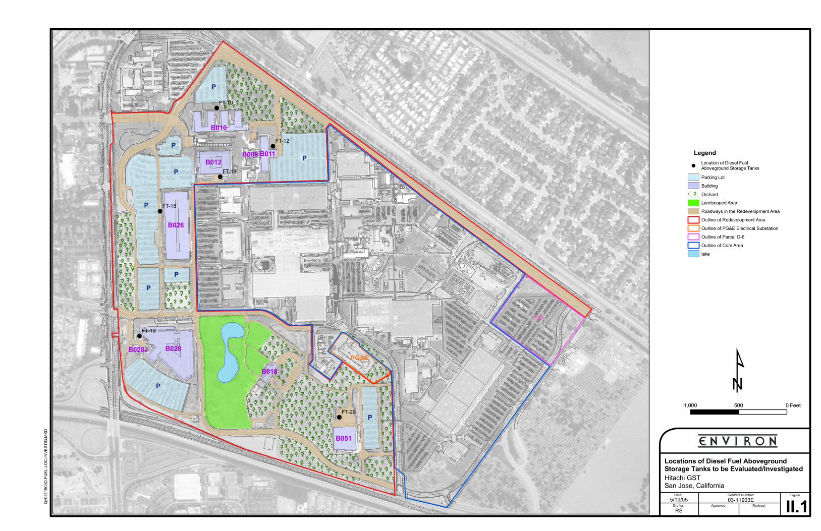
The locations of the ASTs are shown on Figure II.1. The results of this Soil Inspection/Sampling Plan will be used to determine if any mitigation/remediation measures are needed at the Site due to diesel fuel in soils located at or near the diesel fuel ASTs and associated piping. II.2 History The following history for each AST listed above was taken from the Screening HHRA and the CCR. In addition, ENVIRON conducted Site visits as part of the Phase I Environmental Site Assessments (ESAs) prepared by ENVIRON in 2003 and 2004. Building 010 - Diesel Fuel AST (FT-11) Building 010 has a diesel-powered emergency generator with associated 1,000-gallon diesel fuel AST (FT-11). The emergency generator and AST are located north of Building 010. FT-11 is located within a below-grade epoxy-coated concrete vault, with sufficient secondary containment to contain the contents of the tank. The concrete vault is equipped with a roof to prevent collection of precipitation. Hitachi GST personnel reported that the AST is inspected daily. The vault appeared clean and dry during the Site visit and ENVIRON did not observe evidence of releases from the AST. Building 011 - Diesel Fuel AST (FT-12) Building 011 has a diesel-powered emergency generator with associated 1,000-gallon diesel fuel AST (FT-12). The emergency generator and AST are located on the eastern side of Building 011. FT-12 is located within a below-grade epoxy-coated concrete
II-4

vault, with sufficient secondary containment to contain the contents of the tank. The concrete vault is equipped with a roof to prevent collection of precipitation. Hitachi GST personnel reported that the AST is inspected daily. The vault appeared clean and dry during the Site visit and ENVIRON did not observe evidence of releases from the AST. Building 012 - Diesel Fuel AST (FT-13) Building 012 has a diesel-powered emergency generator with an associated 500-gallon diesel fuel AST (FT-13). The emergency generator is located inside Building 012 in the first floor core room. FT-13, which is a double-walled AST, is staged on a concrete pad located outside Building 012 to the south. Hitachi GST personnel reported that the AST is inspected daily. Building 026 - Diesel Fuel AST (FT-18) Building 026 has a diesel-powered emergency generator with associated 2,500-gallon diesel fuel AST (FT-18). The emergency generator and AST are located west of Building 026. FT-18 is located within a below-grade epoxy-coated concrete vault, with sufficient secondary containment to contain the contents of the tank. The concrete vault is equipped with a roof to prevent collection of precipitation. Hitachi GST personnel reported that the AST is inspected daily. The vault appeared clean and dry during the Site visit and ENVIRON did not observe evidence of releases from the AST. Building 028 - Diesel Fuel AST (FT-19) Building 028 has a diesel-powered emergency generator with associated 2,000-gallon diesel fuel AST (FT-19). The emergency generator and AST are located near the northwestern corner of Building 028. FT-19 is located within a below-grade epoxy-coated concrete vault, with sufficient secondary containment to contain the contents of the tank. The concrete vault is equipped with a roof to prevent collection of precipitation. Hitachi GST personnel reported that the AST is inspected daily. The vault appeared clean and dry during the Site visit and ENVIRON did not observe evidence of releases from the AST. Building 051 - Diesel Fuel AST (FT-29) Building 051 has a diesel-powered emergency generator with associated 2,000-gallon diesel fuel AST (FT-29). The emergency generator and AST are located within the fenced area for the Building 051 cooling tower. FT-29 is located in a covered area above an epoxy-coated concrete vault with a 7,000-gallon capacity. Hitachi GST personnel reported that the AST is inspected daily. The vault appeared clean and dry during the Site visit and ENVIRON did not observe evidence of releases from the AST.
II-5
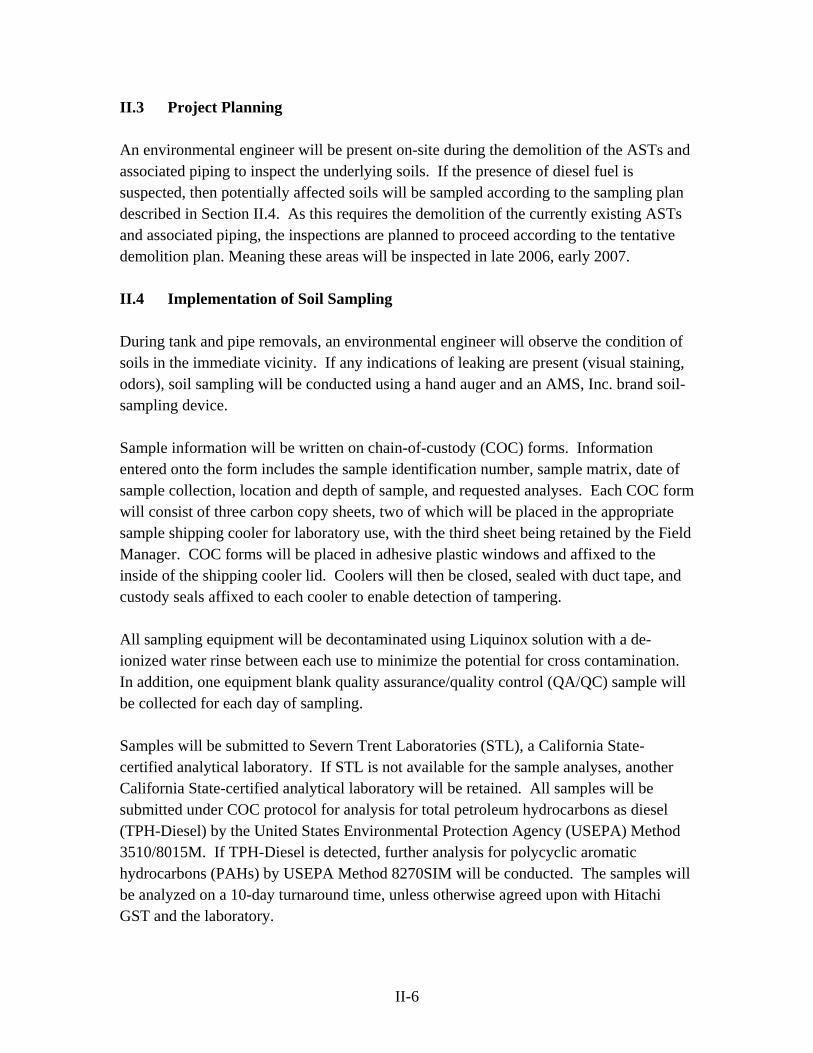
II.3 Project Planning An environmental engineer will be present on-site during the demolition of the ASTs and associated piping to inspect the underlying soils. If the presence of diesel fuel is suspected, then potentially affected soils will be sampled according to the sampling plan described in Section II.4. As this requires the demolition of the currently existing ASTs and associated piping, the inspections are planned to proceed according to the tentative demolition plan. Meaning these areas will be inspected in late 2006, early 2007. II.4 Implementation of Soil Sampling During tank and pipe removals, an environmental engineer will observe the condition of soils in the immediate vicinity. If any indications of leaking are present (visual staining, odors), soil sampling will be conducted using a hand auger and an AMS, Inc. brand soil-sampling device. Sample information will be written on chain-of-custody (COC) forms. Information entered onto the form includes the sample identification number, sample matrix, date of sample collection, location and depth of sample, and requested analyses. Each COC form will consist of three carbon copy sheets, two of which will be placed in the appropriate sample shipping cooler for laboratory use, with the third sheet being retained by the Field Manager. COC forms will be placed in adhesive plastic windows and affixed to the inside of the shipping cooler lid. Coolers will then be closed, sealed with duct tape, and custody seals affixed to each cooler to enable detection of tampering. All sampling equipment will be decontaminated using Liquinox solution with a de-ionized water rinse between each use to minimize the potential for cross contamination. In addition, one equipment blank quality assurance/quality control (QA/QC) sample will be collected for each day of sampling. Samples will be submitted to Severn Trent Laboratories (STL), a California State-certified analytical laboratory. If STL is not available for the sample analyses, another California State-certified analytical laboratory will be retained. All samples will be submitted under COC protocol for analysis for total petroleum hydrocarbons as diesel (TPH-Diesel) by the United States Environmental Protection Agency (USEPA) Method 3510/8015M. If TPH-Diesel is detected, further analysis for polycyclic aromatic hydrocarbons (PAHs) by USEPA Method 8270SIM will be conducted. The samples will be analyzed on a 10-day turnaround time, unless otherwise agreed upon with Hitachi GST and the laboratory.
II-6

Investigation derived waste (IDW) will be collected in appropriate containers that will be labeled and sealed following completion of field activities. Management and disposal of IDW will be the responsibility of Hitachi GST. ENVIRON will provide Hitachi GST with the relevant analytical results to assist Hitachi GST with appropriate management and disposal of IDW. II.5 Data Management and Reporting If samples are collected, ENVIRON will prepare a summary table of the data upon receipt of the analytical results. The results will be compared to the risk-based target concentrations (RBTCs) previously developed for the Site in the Screening HHRA/CCR. Based on this evaluation, a recommendation will be made for no further action, further investigation, and/or remediation. The results of this evaluation will be summarized in a short letter report (plus tables and figures) to be submitted to the Department of Toxic Substances Control (DTSC). II.6 Project Schedule As discussed above, the inspections of tank removals will proceed according to the demolition schedule. II.7 References City of San Jose, California. 2005a. Draft Environmental Impact Report. Hitachi
Campus and Mixed-Use Transit Village Project. General Plan Amendment (GP04-02-01) and Planned Development Rezoning (PDC04-031). SCH#2004072110. Volume I through V. Approved as Final: June 6.
City of San Jose, California. 2005b. First Amendment to the Draft Environmental
Impact Report. Hitachi Campus and Mixed-Use Transit Village Project. General Plan Amendment (GP04-02-01) and Planned Development Rezoning (PDC04-031). SCH#2004072110. Volume I through V. Approved as Final: June 6.
ENVIRON International Corporation (ENVIRON). 2005. Draft Current Conditions
Report, Hitachi Global Technologies, Inc., Redevelopment Area and Endicott Boulevard/Tucson Way, 5600 Cottle Road, San Jose, California. July.
Y:\Hitachi\O-1_to_O-5_Planning\Attach II - Diese Fuel ASTs\ATTACHMENT II.doc
II-7

FIGURES
PG&E
O-6
B028
B026
B012
B051
B010
B011
B018
B009
B028J
P
P
P
P
P
P
P
P
P
FT-29
FT-19
FT-18
FT-13
FT-12
FT-19
1,000 0500 Feet
Q:\03
1190
3D-FU
EL-LO
C-IN
VEST
IG.M
XD
Locations of Diesel Fuel Aboveground Storage Tanks to be Evaluated/InvestigatedHitachi GSTSan Jose, California
03-11903EContract Number: Figure
Approved: Revised:Drafter:
Date:5/19/05
RS II.1
Legend
OrchardLandscaped AreaRoadways in the Redevelopment AreaOutline of Redevelopment AreaOutline of PG&E Electrical SubstationOutline of Parcel O-6Outline of Core Arealake
Parking LotBuilding
Location of Diesel FuelAboveground Storage Tanks

ATTACHMENT III SOIL INSPECTION/SAMPLING PLAN
FOR BURIED CONCRETE TRENCHES, BUILDING 028J AND FORMER WASTE VAULTS 02-04
Original: October 28, 2005 Revision 1: January 31, 2006

III-1
ATTACHMENT III SOIL INSPECTION/SAMPLING PLAN
FOR BURIED CONCRETE TRENCHES, BUILDING 028J, AND FORMER WASTE VAULTS 02-04
TABLE OF CONTENTS III.1 Overview III.2 History III.3 Project Planning III.4 Implementation of Sampling III.5 Data Management and Reporting III.6 Project Schedule III.7 References TABLES III.1 Sample Identification Table FIGURES III.1 Location of Buried Concrete Trenches III.2 026 Building Detail (Former WV-02 original and WV-02 second) III.3 028J Building Detail (Former WV-03 and Spill Containment Tank) III.4 028J Building Detail (Former WV-04)

III-2
ACRONYMS bgs below ground surface Cal/EPA California Environmental Protection Agency CCR Current Conditions Report COC Chain-of-Custody DHS Department of Health Services DJPA David J. Powers & Associates DTSC Department of Toxic Substances Control EIR Environmental Impact Report ESA Environmental Site Assessment GPA General Plan Amendment GST Global Storage Technologies HHRA Human Health Risk Assessment HLA Harding Lawson Associates IBM International Business Machines IDW Investigation Derived Waste OD Outer Diameter OVM Organic Vapor Monitor PCE Perchlorothylene or Tetrachloroethylene PD Planned Development PVC Polyvinyl Chloride RBTC Risk-Based Target Concentration STL Severn Trent Laboratories TCA Trichloroethane TCE Trichloroethylene TTLC Total Threshold Limit Concentration TVH Total Volatile Hydrocarbons USEPA United States Environmental Protection Agency UST Underground Storage Tank VOC Volatile Organic Compounds kg kilogram µg microgram mg milligram ml milliliter min minute

III-3
ATTACHMENT III
SOIL INSPECTION/SAMPLING PLAN FOR BURIED CONCRETE TRENCHES,
BUILDING 028J AND FORMER WASTE VAULTS 02-04 III.1 Overview Recently, David J. Powers & Associates (DJPA) prepared an Environmental Impact Report (EIR) for the proposed General Plan Amendment (GPA) and Planned Development (PD) Zoning on the approximately 332-acre Hitachi Global Storage Technologies, Inc. (Hitachi GST) property located at 5600 Cottle Road, San Jose, California (“the Site”). The City of San Jose Planning Commission certified the Final EIR on June 6, 2005 (City of San Jose 2005a, 2005b). As part of the EIR, ENVIRON International Corporation (ENVIRON) prepared a screening human health risk assessment (Screening HHRA) to evaluate the potential impacts on human health for Parcels O-1 through O-5, termed the Redevelopment Area (approximately 131 acres). In addition, ENVIRON prepared a Draft Current Conditions Report (CCR) (ENVIRON 2005) for these same parcels. The purpose of this Sampling Plan is to address the following areas identified in the Screening HHRA/Draft CCR as needing additional evaluation/investigation of soil:
A concrete trench, that formerly contained pipes which were connected to former waste vaults and tanks, is located west of Building 026 and runs in a north-south direction along the entire length of Parcel O-2. Given the history of this trench, ENVIRON recommends that an environmental engineer inspect the area surrounding the concrete trench after it is removed as part of redevelopment activities. If any indications of leaking are present (cracking, visual staining), soil sampling should be conducted.
Near the former WV-02 (original) and former WV-02 (second) by Building 026,
samples should be collected following building demolition for analysis of trichlorethene (TCE) and metals (specifically total chromium and nickel).
A concrete trench that formerly contained pipes runs through Parcel O-3 in a north-
south direction. Given the history of this trench, ENVIRON recommends that an environmental engineer inspect the area surrounding the concrete trench once it has been removed. If any indications of leaking are present (cracking, visual staining), soil sampling should be conducted.
III-4
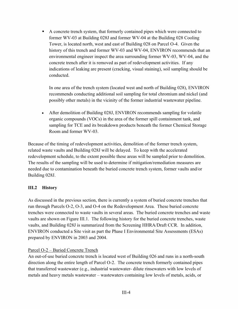
A concrete trench system, that formerly contained pipes which were connected to former WV-03 at Building 028J and former WV-04 at the Building 028 Cooling Tower, is located north, west and east of Building 028 on Parcel O-4. Given the history of this trench and former WV-03 and WV-04, ENVIRON recommends that an environmental engineer inspect the area surrounding former WV-03, WV-04, and the concrete trench after it is removed as part of redevelopment activities. If any indications of leaking are present (cracking, visual staining), soil sampling should be conducted.
In one area of the trench system (located west and north of Building 028), ENVIRON recommends conducting additional soil sampling for total chromium and nickel (and possibly other metals) in the vicinity of the former industrial wastewater pipeline.
• After demolition of Building 028J, ENVIRON recommends sampling for volatile organic compounds (VOCs) in the area of the former spill containment tank, and sampling for TCE and its breakdown products beneath the former Chemical Storage Room and former WV-03.
Because of the timing of redevelopment activities, demolition of the former trench system, related waste vaults and Building 028J will be delayed. To keep with the accelerated redevelopment schedule, to the extent possible these areas will be sampled prior to demolition. The results of the sampling will be used to determine if mitigation/remediation measures are needed due to contamination beneath the buried concrete trench system, former vaults and/or Building 028J. III.2 History As discussed in the previous section, there is currently a system of buried concrete trenches that run through Parcels O-2, O-3, and O-4 on the Redevelopment Area. These buried concrete trenches were connected to waste vaults in several areas. The buried concrete trenches and waste vaults are shown on Figure III.1. The following history for the buried concrete trenches, waste vaults, and Building 028J is summarized from the Screening HHRA/Draft CCR. In addition, ENVIRON conducted a Site visit as part the Phase I Environmental Site Assessments (ESAs) prepared by ENVIRON in 2003 and 2004. Parcel O-2 – Buried Concrete Trench An out-of-use buried concrete trench is located west of Building 026 and runs in a north-south direction along the entire length of Parcel O-2. The concrete trench formerly contained pipes that transferred wastewater (e.g., industrial wastewater- dilute rinsewaters with low levels of metals and heavy metals wastewater – wastewaters containing low levels of metals, acids, or
III-5
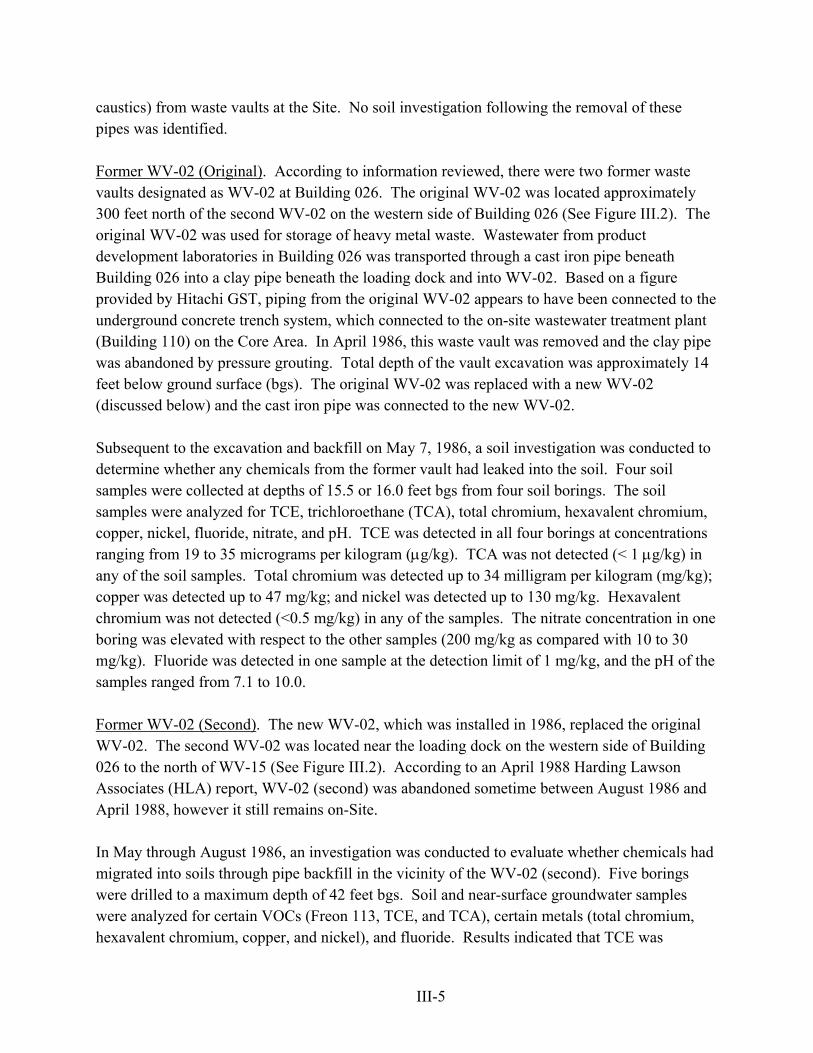
caustics) from waste vaults at the Site. No soil investigation following the removal of these pipes was identified. Former WV-02 (Original). According to information reviewed, there were two former waste vaults designated as WV-02 at Building 026. The original WV-02 was located approximately 300 feet north of the second WV-02 on the western side of Building 026 (See Figure III.2). The original WV-02 was used for storage of heavy metal waste. Wastewater from product development laboratories in Building 026 was transported through a cast iron pipe beneath Building 026 into a clay pipe beneath the loading dock and into WV-02. Based on a figure provided by Hitachi GST, piping from the original WV-02 appears to have been connected to the underground concrete trench system, which connected to the on-site wastewater treatment plant (Building 110) on the Core Area. In April 1986, this waste vault was removed and the clay pipe was abandoned by pressure grouting. Total depth of the vault excavation was approximately 14 feet below ground surface (bgs). The original WV-02 was replaced with a new WV-02 (discussed below) and the cast iron pipe was connected to the new WV-02. Subsequent to the excavation and backfill on May 7, 1986, a soil investigation was conducted to determine whether any chemicals from the former vault had leaked into the soil. Four soil samples were collected at depths of 15.5 or 16.0 feet bgs from four soil borings. The soil samples were analyzed for TCE, trichloroethane (TCA), total chromium, hexavalent chromium, copper, nickel, fluoride, nitrate, and pH. TCE was detected in all four borings at concentrations ranging from 19 to 35 micrograms per kilogram (µg/kg). TCA was not detected (< 1 µg/kg) in any of the soil samples. Total chromium was detected up to 34 milligram per kilogram (mg/kg); copper was detected up to 47 mg/kg; and nickel was detected up to 130 mg/kg. Hexavalent chromium was not detected (<0.5 mg/kg) in any of the samples. The nitrate concentration in one boring was elevated with respect to the other samples (200 mg/kg as compared with 10 to 30 mg/kg). Fluoride was detected in one sample at the detection limit of 1 mg/kg, and the pH of the samples ranged from 7.1 to 10.0. Former WV-02 (Second). The new WV-02, which was installed in 1986, replaced the original WV-02. The second WV-02 was located near the loading dock on the western side of Building 026 to the north of WV-15 (See Figure III.2). According to an April 1988 Harding Lawson Associates (HLA) report, WV-02 (second) was abandoned sometime between August 1986 and April 1988, however it still remains on-Site.
In May through August 1986, an investigation was conducted to evaluate whether chemicals had migrated into soils through pipe backfill in the vicinity of the WV-02 (second). Five borings were drilled to a maximum depth of 42 feet bgs. Soil and near-surface groundwater samples were analyzed for certain VOCs (Freon 113, TCE, and TCA), certain metals (total chromium, hexavalent chromium, copper, and nickel), and fluoride. Results indicated that TCE was
III-6
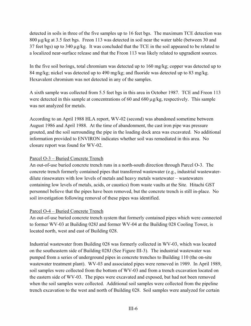
detected in soils in three of the five samples up to 16 feet bgs. The maximum TCE detection was 800 µg/kg at 3.5 feet bgs. Freon 113 was detected in soil near the water table (between 30 and 37 feet bgs) up to 340 µg/kg. It was concluded that the TCE in the soil appeared to be related to a localized near-surface release and that the Freon 113 was likely related to upgradient sources.
In the five soil borings, total chromium was detected up to 160 mg/kg; copper was detected up to 84 mg/kg; nickel was detected up to 490 mg/kg; and fluoride was detected up to 83 mg/kg. Hexavalent chromium was not detected in any of the samples.
A sixth sample was collected from 5.5 feet bgs in this area in October 1987. TCE and Freon 113 were detected in this sample at concentrations of 60 and 680 µg/kg, respectively. This sample was not analyzed for metals.
According to an April 1988 HLA report, WV-02 (second) was abandoned sometime between August 1986 and April 1988. At the time of abandonment, the cast iron pipe was pressure grouted, and the soil surrounding the pipe in the loading dock area was excavated. No additional information provided to ENVIRON indicates whether soil was remediated in this area. No closure report was found for WV-02. Parcel O-3 – Buried Concrete Trench An out-of-use buried concrete trench runs in a north-south direction through Parcel O-3. The concrete trench formerly contained pipes that transferred wastewater (e.g., industrial wastewater- dilute rinsewaters with low levels of metals and heavy metals wastewater – wastewaters containing low levels of metals, acids, or caustics) from waste vaults at the Site. Hitachi GST personnel believe that the pipes have been removed, but the concrete trench is still in-place. No soil investigation following removal of these pipes was identified. Parcel O-4 – Buried Concrete Trench An out-of-use buried concrete trench system that formerly contained pipes which were connected to former WV-03 at Building 028J and former WV-04 at the Building 028 Cooling Tower, is located north, west and east of Building 028. Industrial wastewater from Building 028 was formerly collected in WV-03, which was located on the southeastern side of Building 028J (See Figure III-3). The industrial wastewater was pumped from a series of underground pipes in concrete trenches to Building 110 (the on-site wastewater treatment plant). WV-03 and associated pipes were removed in 1989. In April 1989, soil samples were collected from the bottom of WV-03 and from a trench excavation located on the eastern side of WV-03. The pipes were excavated and exposed, but had not been removed when the soil samples were collected. Additional soil samples were collected from the pipeline trench excavation to the west and north of Building 028. Soil samples were analyzed for certain

III-7
metals (total chromium, hexavalent chromium, copper, iron, nickel, and zinc). These are the chemicals International Business Machines (IBM) identified as being potentially found in the industrial wastewater conveyed through WV-03. Based on the sampling results, total chromium and nickel exceeded at least one of their respective risk-based target concentrations (RBTCs) in the vicinity of the former pipeline running from WV-03 to Building 110. Hexavalent chromium was non-detect in most samples and below RBTCs where detected. After sampling for metals, the majority of the excavated soil from the pipeline removal was subsequently backfilled into the excavation. Cooling tower blowdown from the Building 028 Cooling Tower, which was operated from 1971 until approximately 1994, was formerly collected in WV-04 (See Figure III.4). WV-04 was an approximately 1,200-gallon concrete sump with a polyvinyl chloride (PVC) liner (referred to as tank T-1). The blowdown was transferred via a series of underground pipes within concrete trenches to Building 110. In 1994, WV-04 (Tank T-1) was closed under a permit (No. C48874) issued by the City of San Jose Hazardous Materials Program. Closure activities included decontaminating the sump, conducting confirmatory surface wipe sampling for certain metals, backfilling with compacted soil, and installing a concrete cap. In addition, underground piping in the concrete trench system located between WV-04 and the east side of Building 028 was excavated and removed in 1994. The buried trench system included pipes containing industrial wastewater, heavy metals wastewater, and brine wastewater. As part of closure activities, soil samples were collected and analyzed for metals from beneath WV-04 and at four locations beneath the concrete trench. According to the sampling report, results indicated concentrations of metals below California’s Total Threshold Limit Concentrations (TTLC). It was concluded that soils beneath WV-04 and the trench were not impacted by metals and no additional excavation was required. Building 028J. Building 028J, which is an approximately 2,000-square foot building, is located adjacent to the west of Building 028. Building 028J was constructed in 1971 as the chemical and chemical waste storage area for Building 028. According to Hitachi GST personnel, primarily drums of solvents and cylinders of compressed gases were stored in Building 028J from 1971 until approximately 1989. According to a map of Building 028J dated 1984, the building was divided into two main chemical storage areas: “solvent storage area” and “user organics”. During the Site visit, ENVIRON observed cracks within the concrete floor leading to drains in the former solvent storage area in Building 028J. At the time of the Site visit, the cracks and drains appeared to have been sealed. Subsequent to 1989, Building 028J was vacant for several years before it was used as a staging area for the Site’s landscaping contractor. According to documents reviewed, an underground spill containment tank without secondary containment was formerly located east of Building 028J. This buried tank was removed in early-1982. An underground 300-gallon solvent spill storage tank was formerly located within the

III-8
northern side of Building 028J. This buried tank was removed in August 1986 as part of routine upgrading of facilities. As described above, a former waste vault, WV-03, is associated with Building 028J. A number of soil investigations associated with Building 028J have been conducted, as described below.
- Spill Containment Tank Removal. In early-1982, an underground spill containment tank
with no secondary containment located east of Building 028J was removed. The tank, which was buried approximately 10 feet bgs, was less than four feet in diameter and slightly more than four feet long. In July 1982, an investigation was conducted to characterize the chemical content of soil and groundwater beneath the spill containment tank. Two borings were drilled to a maximum depth of 43.5 feet bgs. Soil and groundwater samples were analyzed for 13 organic compounds, which represent all the chemicals that may have been in the tank during the period of its use. Freon 113, TCA, TCE, tetrachloroethylene (PCE), chloroform, carbon tetrachloride, and acetone were detected in unsaturated soils and in groundwater. Ethyl amyl ketone, petroleum naphtha, kerosene, isopropyl alcohol, isophorone, and xylene were not detected above their respective detection limits. Freon 113 was detected up to 23 µg/kg; TCA was detected up to 71 µg/kg; TCE was detected up to 40 µg/kg; PCE was detected up to 80 µg/kg; chloroform was detected up to 1,600 µg/kg; carbon tetrachloride was detected up to 6.7 µg/kg; and acetone was detected up to 5.1 mg/kg in unsaturated soils. Based on information reviewed, no remedial actions appear to have been conducted.
- Solvent Tank Removal. A buried 300-gallon solvent spill storage tank was removed
during routine upgrading of facilities from within the northern side of Building 028J on August 12, 1986. When that underground storage tank (UST) was installed in approximately 1978, it was set in wet concrete, which formed a continuous saddle two to three inches thick at the base of the tank. The concrete saddle, which was approximately 3.5 feet bgs, was not removed as part of the tank excavation. The tank was intended to be used as a solvent spill storage tank, but the tank was never used. Two soil samples from two soil borings were collected from a depth of 4.5 feet bgs. One sample was collected beneath the east end of the concrete saddle and the other sample was collected beneath the west end. The soil samples were analyzed for total chromium, copper, nickel, and for chlorinated and nonchlorinated solvents. Results indicated TCE concentrations up to 10 µg/kg and metal concentrations within background ranges. The source of the TCE in the soil was unknown, but could be from the former nearby spill containment tank (discussed above). The report recommends investigating further the source of TCE in soils. The excavation was backfilled with clean, imported sand.
- TCE Investigation beneath Chemical Storage Room and WV-03. In September 1986, an
investigation was conducted to determine whether the Chemical Storage Room in

III-9
Building 028J or WV-031 were possible sources for the TCE found in the soils during previous investigations. Three soil borings were drilled to 10 feet bgs and one soil boring was drilled to 30 feet bgs beneath the Chemical Storage Room and WV-03. Eighteen soil samples from the four borings were collected and analyzed for Freon 113, TCA, TCE, methylene chloride, isophorone, and acetone. TCE was detected in samples from all four borings up to 33 µg/kg, and TCA was detected in samples from two of the borings up to 9 µg/kg. The remaining constituents were not detected in any of the samples. According to the soil investigation report, the Department of Health Services (DHS) had not established an action level for TCE in soils; however, the IBM internal guideline was 500 µg/kg. Based on this internal guideline, it was concluded that no further investigations concerning TCE in soils at Building 028J were necessary.
III.3 Project Planning Soil and soil gas samples will be collected from near the buried concrete trench, former waste vaults and Building 028J according to the sampling plan presented in Section III.4. III.4 Implementation of Sampling All work will be performed or supervised by a California Registered Professional Engineer or Geologist. ENVIRON personnel will be present during all sampling activities to obtain samples of subsurface materials, make observations of work area conditions, conduct health and safety monitoring of organic vapors during temporary probe installation, and provide technical assistance as required. Prior to initiating field activities, ENVIRON will conduct a survey of underground utilities at proposed sampling locations, arrange for drilling and analytical laboratory subcontractors, and update the Site-specific health and safety plan. Soil gas samples will be collected prior to soil sample collection. Based on the results of soil gas sampling, the locations of soil samples may be adjusted.
Soil Gas Sampling Soil gas samples will be collected from 20 locations (SG-TR-1 through 18, SG-028J-1, and SG-028J-2). Proposed soil gas sampling locations are summarized on Table III.1 and shown on Figure III.1, III.2 and III.3. Soil gas samples will be collected from a depth of five and 10 feet bgs using a Geoprobe™-type direct push drilling rig. Soil gas samples will be collected in general conformance with the California Environmental Protection Agency (Cal/EPA) Department of Toxic Substances Control (DTSC) Advisory on Active Soil Gas Investigations, dated January 28, 2003 (the “Cal/EPA Advisory”).
1 Further evaluation/investigation concerning WV-03 at Building 028J is discussed above.

III-10
At each sampling location, soil gas samples will be collected from the desired depth via temporary probes. The temporary soil gas probes will be constructed of 1-inch outer diameter (OD) chrom-moly steel with an inert 1/8-inch diameter nylaflow tube that runs down the center of the probe to sampling ports beneath the tip. The temporary probe will be driven into the ground with an electric rotary hammer or similar apparatus. Once the desired depth is reached, the probe will be retracted slightly, which opens the tip and exposes the vapor sampling port. Following equilibration, soil gas will be withdrawn from the nylaflow tubing using a small calibrated syringe connected via a shut-off valve. The first three dead volumes of vapor will be discarded to purge the sample tubing. The next 20 cubic centimeters of soil gas will be withdrawn in the syringe, plugged and immediately transferred to a mobile laboratory for analysis or collected in a SummaTM canister if a fixed base laboratory is to be used. Per Cal/EPA’s Advisory, the flowrate for purging or sampling shall not exceed 200 milliliters per minute (ml/min). The temporary soil gas probe will be sealed as described in the Cal/EPA Advisory. During installation of the probe, hydrated bentonite will be used to seal around the drive rod at ground surface, and the inner soil gas pathway from probe tip to the surface will be sealed via an adapter fitted with an o-ring and connected to the probe tip. Leak tests will be conducted using 1,1,1-difluoroethane gas that is sprayed during sampling at locations where there is the potential for ambient air to enter the sampling system. The soil gas samples will be analyzed using a mobile laboratory that is brought to the Site. The samples will be analyzed for VOCs and total volatile hydrocarbons (TVH) using the United States Environmental Protection Agency (USEPA) Method 8260B. The target detection limit for VOCs will be 0.08 µg/L. Roughly ten percent of the samples will be sent to a fixed base laboratory for confirmation of mobile laboratory results. These duplicate samples will be collected in SummaTM canisters and analyzed using USEPA Method TO-14. A chain-of-custody (COC) form will be completed to maintain the custodial integrity of each soil gas sample. A minimum of one method blank will be collected each sampling day to verify the effectiveness of decontamination procedures and to detect any possible interference from ambient air. One duplicate sample will also be collected and analyzed per day. Laboratory Control Samples and Dilution Procedure Duplicates will be done in accordance with Cal/EPA’s Advisory (Section 2.7.1C). In addition, a purge volume test at a minimum of one location near potential contaminant sources and a probe leak test will be conducted per sampling day as described in Section 2.3 and 2.4 of Cal/EPA’s Advisory. Probe installation times, sample collections times, purge volume times and other pertinent data will be recorded in the field for eventual inclusion in a soil gas report.

III-11
To minimize the potential for cross-contamination between sample locations, all external probe parts will be cleaned and decontaminated before insertion. The internal nylaflow tubing and calibrated syringes will be replaced prior to insertion at new sampling locations. Soil Sampling: Buried Concrete Trench/Former Waste Vaults Soil samples will be collected from the concrete trench/former waste vault locations summarized on Table III.1 and as shown on Figure III.1, III.2 and III.3. The exact location of these soil samples may be adjusted following receipt of soil gas sampling results. Two soil borings will be advanced in the area of WV-02 (original) (WV-02-1 and WV-02-2) and two soil borings will be advanced in the area of WV-02 (second) (WV-02-5 and WV-02-6) to a depth of 20 feet bgs. (As discussed in Section III.2, previous soil samples at the former WV-02 (original) were collected at 15-16 feet bgs. For former WV-02 (second), previous soil samples were collected at a maximum depth of 42 feet bgs, with maximum TCE concentrations at depths less than five feet.) Samples will be collected at nominal five-foot intervals or when evidence of contaminated soils is present. In addition, a soil boring will be advanced approximately every 100 feet along the associated clay pipeline, also to a depth of 20 feet bgs. It is anticipated that two soil borings will be advanced along the associated pipeline (WV-02-3 and –4). These locations are shown on Figure III.2. Soil samples will be collected from native soil as close to the bottom of the trenches as physically possible (it is anticipated that this will be approximately six to eight feet bgs based on previous investigations). Soil samples will be collected from approximately nine locations to characterize soil beneath the concrete trench (TR-1 through TR-9) (See Figure III.1). Soil samples will be collected from native soil as close to the bottom of the former waste vaults WV-3 and WV-4 as physically possible (it is anticipated that this will be approximately six to eight feet bgs based on previous investigations). Soil samples will be collected from approximately two locations to characterize soil beneath former WV-03 (WV-03-1 and WV-03-2) and one soil sample will be collected from soil beneath former WV-04 (WV-04-1) (See Figures III.3 and III.4). To preserve the integrity of the trench/vaults/clay pipeline, boreholes will not be drilled through the trench or vault or pipeline. Soil samples will be collected from borings installed at a 28 degree angle next to the trench/waste vault/pipeline using a truck-
III-12
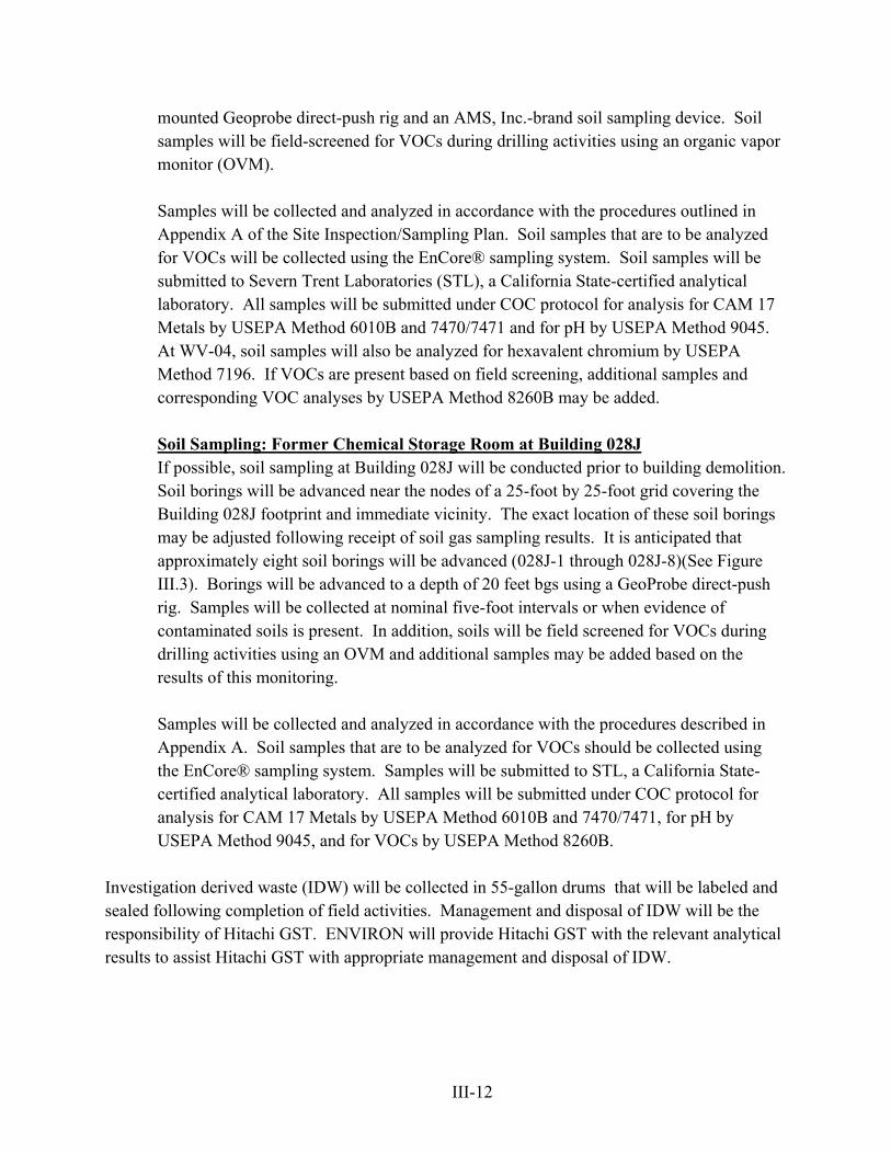
mounted Geoprobe direct-push rig and an AMS, Inc.-brand soil sampling device. Soil samples will be field-screened for VOCs during drilling activities using an organic vapor monitor (OVM). Samples will be collected and analyzed in accordance with the procedures outlined in Appendix A of the Site Inspection/Sampling Plan. Soil samples that are to be analyzed for VOCs will be collected using the EnCore® sampling system. Soil samples will be submitted to Severn Trent Laboratories (STL), a California State-certified analytical laboratory. All samples will be submitted under COC protocol for analysis for CAM 17 Metals by USEPA Method 6010B and 7470/7471 and for pH by USEPA Method 9045. At WV-04, soil samples will also be analyzed for hexavalent chromium by USEPA Method 7196. If VOCs are present based on field screening, additional samples and corresponding VOC analyses by USEPA Method 8260B may be added. Soil Sampling: Former Chemical Storage Room at Building 028J If possible, soil sampling at Building 028J will be conducted prior to building demolition. Soil borings will be advanced near the nodes of a 25-foot by 25-foot grid covering the Building 028J footprint and immediate vicinity. The exact location of these soil borings may be adjusted following receipt of soil gas sampling results. It is anticipated that approximately eight soil borings will be advanced (028J-1 through 028J-8)(See Figure III.3). Borings will be advanced to a depth of 20 feet bgs using a GeoProbe direct-push rig. Samples will be collected at nominal five-foot intervals or when evidence of contaminated soils is present. In addition, soils will be field screened for VOCs during drilling activities using an OVM and additional samples may be added based on the results of this monitoring. Samples will be collected and analyzed in accordance with the procedures described in Appendix A. Soil samples that are to be analyzed for VOCs should be collected using the EnCore® sampling system. Samples will be submitted to STL, a California State-certified analytical laboratory. All samples will be submitted under COC protocol for analysis for CAM 17 Metals by USEPA Method 6010B and 7470/7471, for pH by USEPA Method 9045, and for VOCs by USEPA Method 8260B.
Investigation derived waste (IDW) will be collected in 55-gallon drums that will be labeled and sealed following completion of field activities. Management and disposal of IDW will be the responsibility of Hitachi GST. ENVIRON will provide Hitachi GST with the relevant analytical results to assist Hitachi GST with appropriate management and disposal of IDW.
III-13
III.5 Data Management and Reporting Upon receipt of the analytical results, ENVIRON will prepare a summary table of the data and compare the results to naturally occurring background concentrations in soil and the RBTCs previously developed for the Site in the Screening HHRA/Draft CCR. Based on this evaluation, a recommendation will be made for no further action, further investigation, and/or remediation. The results of this evaluation will be summarized in a short letter report (plus tables and figures) to be submitted to the DTSC. III.6 Project Schedule It is anticipated that the soil gas sampling will take approximately two weeks to complete (including field and analytical) after authorization to proceed. To the extent possible, it is recommended that soil samples be collected following receipt and evaluation of the soil gas survey results. It is recommended that the soil gas samples be collected in week one. In week two, the soil gas results will be evaluated and the proposed soil sample locations according accordingly. The soil sampling would be conducted in week three. The soil samples will be analyzed on a 10-day turnaround time, unless otherwise agreed upon with Hitachi GST and the laboratory. III.7 References City of San Jose, California. 2005a. Draft Environmental Impact Report. Hitachi Campus and
Mixed-Use Transit Village Project. General Plan Amendment (GP04-02-01) and Planned Development Rezoning (PDC04-031). SCH#2004072110. Volume I through V. Approved as Final: June 6.
City of San Jose, California. 2005b. First Amendment to the Draft Environmental Impact
Report. Hitachi Campus and Mixed-Use Transit Village Project. General Plan Amendment (GP04-02-01) and Planned Development Rezoning (PDC04-031). SCH#2004072110. Volume I through V. Approved as Final: June 6.
ENVIRON International Corporation (ENVIRON). 2005. Draft Current Conditions Report,
Hitachi Global Technologies, Inc., Redevelopment Area and Endicott Boulevard/Tucson Way, 5600 Cottle Road, San Jose, California. July.
Y:\Hitachi\O-1_to_O-5_Planning\Attach III - Trenches-O28J-WV 02-03-04\Attachment III Revised 1.31.06