history of metal casting - marmara...
TRANSCRIPT

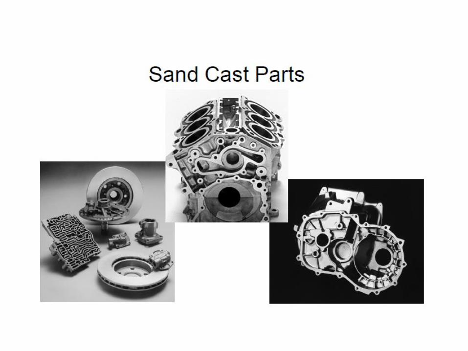
Sand Casting
Prof. Dr. Altan Turkeli
MSE-432
Foundry Technology
• In order to produce an “Alloy”, different metals should melt to obtain right composition.
• This liquid should solidify at the different cooling rates
• At slow cooling rates in the case of ingot casting, component casting
• At the high cooling rates in the case of powder metallurgy, rapid solidification


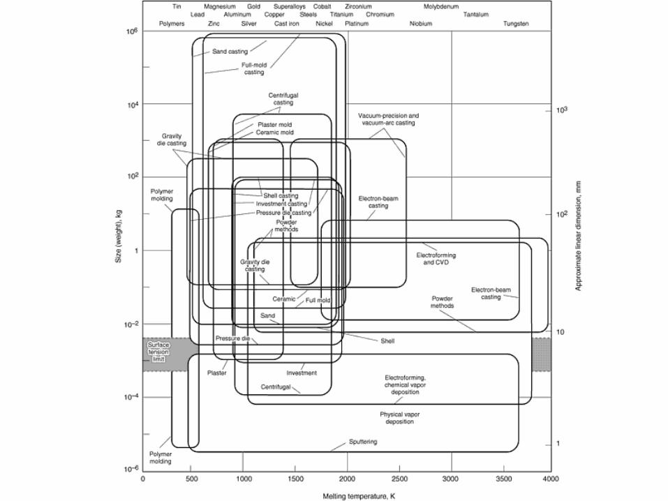
The nine classes of manufacturing processes. The first row contains the primary forming (shaping) processes. The processes in the lower vertical
column are the secondary forming and finishing processes.


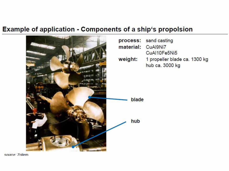


Copper Alloy Casting


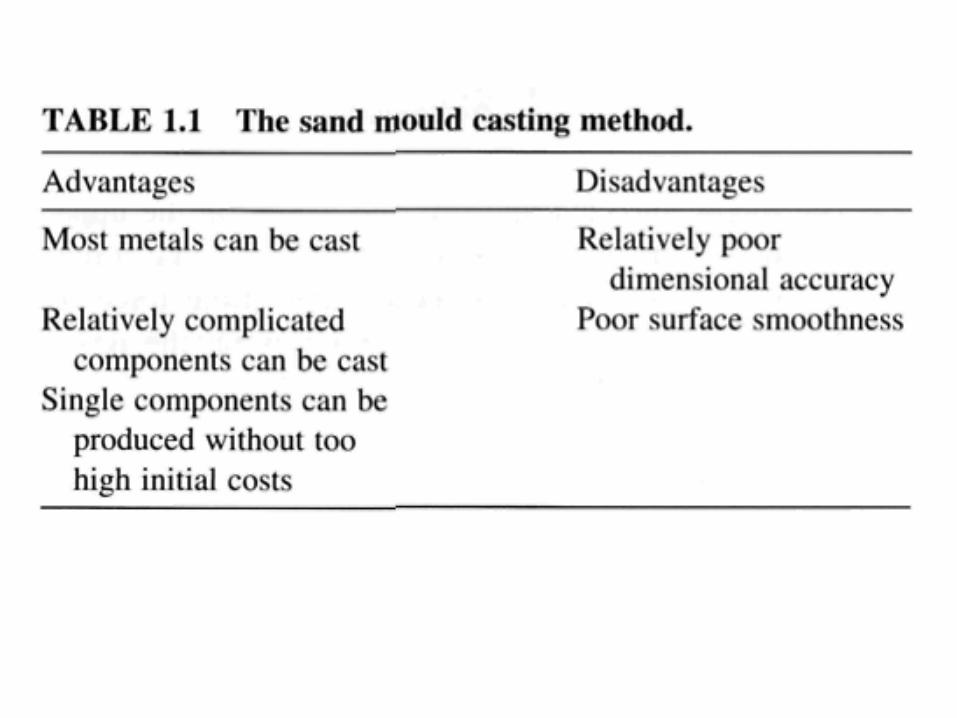
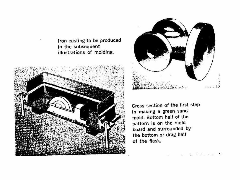
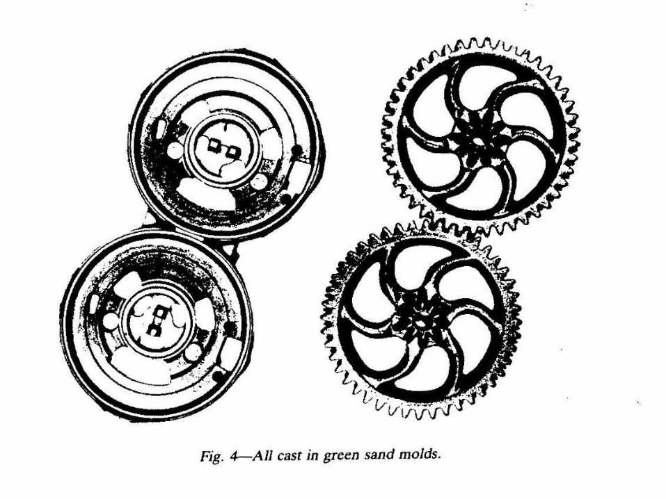
Green Sand Molds
• This is the most widely used molding method for small to medium castings in all metals.
• The process utilizes a mold made of compressed or compacted moist sand. The term green denotes the presence of moisture in the molding sand, and indicates that the mold is not baked or dried.
• The advantage of green sand casting is that the process can be of short time cycle; e.g. sand preparation, mold making; closing, pouring and shakeout are ideally suited to a mechanized, continuous process.

• Green sand is the best known of all the sand casting molding methods, as the molds may be poured without further conditioning. This type molding is most adaptable to light, bench molding for medium sized castings or for use with production molding machines.
• The majority of all small, repetitive, medium and medium-heavy castings are made in green sand molds. Automotive castings, farm machinery, household equipment, valves, fittings, internal combustion engines, pumps, compressors,railroad parts, mining parts, construction machinery and castings for general industrial usage are made from green sand molds.


• Green sand is used in both the ferrous and nonferrous industries to a far greater degree than all other molding processes combined.
• About 90 percent of the approximately 20 million tons of castings produced annually inthe US are produced in green sand molds.

High Pressure (High Density) Molding
• There have been dramatic changes in foundry molding systems in the past decade.
• 20 years ago, a foundry producing 3000 or 4000 molds in a day could have 20 or more molding machines. This volume of production is being produced today in many foundries on one automatic molding line in two shifts. It is not uncommon for a foundry to depend on one or two automatic molding machines for almost all of their production.

• In recent years automatic high pressure or high density molding has been widely adapted for the casting of most metals. High pressure (high density) molding has virtually eliminated the past problems of mold-wall movement. Mold-wall movement has been markedly aggravated by the moisture content of the molding sand, the density of the molds and the mold surface hardness.
• High pressure molding practices have allowed lower moisture contents in the molding sand, so that higher mold densities can be achieved with higher capacity molding machines. Thus, castings have considerably better dimensional accuracy are produced. In general, the surface finish of the castings is improved and they are closer to pattern accuracy

• There is no known limit to the size of castings which can be made by high-pressure (high density) molding. Molds can be 5-6 feet wide, up to 10 feet long with depths of 2 feet or more, and there does not seem to be a restriction on mold cycle speed. Speeds are a factor of degree of automation rather than pressure, yet cycle speeds at less than 10 sec are a reality.
• Most known alloys are being poured in high-density molds. Gray, ductile and malleable iron, steel, high alloy steel, brasses, bronzes, aluminum and magnesium castings are being produced daily.

• The advantages of high pressure molding are castings with closer dimensional tolerances, consistently uniform casting weight, better surface finish, increased productivity and lower costs.
• Other advantages which can be derived from high pressure (high density) molding are reduced feed metal and improved casting soundness, reduced cleaning costs and minimum setup operations for machining because of casting dimensional accuracy.


Flaskless Molding
• One of the latest innovations in green sand molding methods and concepts has been the introduction of flaskless molding-with both vertical as well as horizontal partings.
• Contrary to any misconceptions, a flask must be used on all green sand molding primarily for containment of sand while it is firmed about the pattern.
• In flaskless molding (whether vertical or horizontal) instead of using "tight" individual flasks for each mold produced, the master flask is contained as an integral unit of the totally mechanized mold producing system.
• Flaskless molding has been in use since about the turn of the century and, with the introduction of the jolt squeezer in about 1920, removable flasks have been widely used in the production of hundreds of thousands of molds.
• In 1957 Professor V.A. Jeppesen of the Copenhagen Technical Institute invented one of the first production machines. The emphasis and potential of the vertically parted concept was soon realized as a vital contribution to increased productivity in the production of molds.

• Through advanced engineering techniques as well as constant modification and improvements, vertical flaskless molding has achieved notable production as well as casting quality and has attained new heights of casting dimensional tolerance and accuracy.
• The vertical flaskless system is suited to gray, malleable and ductile iron as well as steel, aluminum and brass.
• In the vertical flaskless system, the completely contained molding unit blows and squeezes a mold against a pattern (or multiple patterns) which has been designed for a vertical gating system.
• Molds of this type can be produced in very high quantities per hour, and of high density (mold hardness ranging from 85-95 B scale) with excellent dimensional reproducibility. The production efficiencies of vertical flaskless molding which may be realized are impressive. Some of these are listed below:

• Uniform preliminary blown mold density.
• Uniform dense final squeezed mold with over 85 mold hardness.
• Highly dense mold allows maximum effective use of mold surfacefor intricate castings.
• Adjustable draw-both speed and lengths.
• Adjustable mold thickness, blow pressure and squeeze pressure.
• Maximum output (up to 600 molds per hour) with minimum manpower and floor space.

• Mold shift is eliminated by the use of extremely rugged rams, platens and guides which maintain pattern impressions accuratelyopposite during closing and pouring so that flask requirement is reduced or eliminated.
• Pour conveyor and cooling conveyor are an integrated part of the system.
• No flasks are required and. therefore, need for an involved return system is eliminated.
• No regular check on flask parts is necessary.
• Labor costs are reduced because the molding operation is entirely automatic.
• Produces a dimensionally accurate casting because of the high compaction pressures used.

• Economies effected with vertical flaskless molding:
• Elimination of flasks, cost of bushings and pins and maintenance required for flask conditioning.
• Elimination of flask handling equipment.
• Elimination of clamps or weights.
• A rapid molding cycle.
• Excellent utilization of productive floor space.
• Minimum manpower requirements.
• Rapid pattern change.

• The high density (high pressure) mold hardness minimizes mold wall movement, thus allowing accurate casting wall dimensions and increasing accuracy across the parting line.
• Fins are also essentially eliminated and shift is significantly reduced from that previously experienced in cope and drag tight flask molding.
Advantages of Flaskless Molding
• No flask storage problem.• No continual flask repair.• Working area noise is reduced. Handling, transferring
and stacking of flasks causes much excessive noise duringthe various sequences of mold and casting processing.
• The one necessary snap or slip flask which must be used can be made stronger, more durable and more precise than is practical with a multiflask system. (Some "flaskless molds" may be poured with the use of slip flasks.)
Advantages of Flaskless Molding
• Mold gas ignition at the parting is more spontaneous.
• Cleaning of flasks as they return from shakeout is no longer necessary.
• Flaskless molding offers an easier mold dump, shakeout or knock-out.
• The need for handling of flasks returning from the shakeout is eliminated.
• Flaskless molding incurs less total capitalization costs.
• Lower total cost per mold is obtainable.

Disadvantages of Flaskless Molding
• Location of the casting cavity. When castings are crowded and very close to the outside mold wall, flaskless molding may be impractical to use. Mold handling may be more difficult as flasks provide convenient "handles" for lifting or pushing.
• The cope and drag are more likely to shift if the mold is bumped or jostled during handling.
• Jackets and weights are required with certain types of flaskless molds. If jackets are required, it presents a problem of proper placement over the mold.

Disadvantages of Flaskless Molding
• In some cases, more castings per mold can be obtained using larger flasks. The size of the castings produced is limited by the size of the mold.
• Complicated coring-up is impossible because of the nature of the high pressure compaction of this sand.
Disamatic Molding
• Currently, all Metal Technologies foundries utilize Disamatic Molding Machines to produce molds for our castings. Disamaticsoffer a highly efficient means of rapidly and automatically creating a string of flasklessmolds. These molds are built for vertical casting and are created in a vertical molding environment. For an explanation of the process, read through the text below and click on the thumbnail images to see illustrations.

Disamatic Molding

Disamatic Molding Step 1. Sand is blown into the Molding
Chamber from above.

Disamatic Molding Step 2. The Ram advances, pushing the Ram Pattern. This
compresses the sand in the Molding Chamber to form mold impressions. Thencompression creates opposite halves of
consecutive molds to placed in the mold string.

Disamatic Molding Step 2. (cont) Castings cannot be formed using a single mold, but
when a new mold is placed in the mold string, its leading edge meets the trailing edge of the previous mold to create a
completed mold cavity.

Disamatic Molding Step 3. The Swing Pattern moves back and up to allow the mold to exit the
Molding Chamber.

Disamatic Molding Step 4. The Ram extends, pushing the
new mold into the existing mold string.

Disamatic MoldingStep 5. The Ram and Swing patterns return to
their original position to begin the process again.

Disamatic MoldingStep 6. Sand is blown into the Molding Chamber for the next
mold. A little further down the mold string, iron is poured into the top of a formed mold via the pouring sprue left by the
pattern impressions.

Skin-Dried Molds• Skin-dried or air-dried molds are sometimes preferred to
green sand molds where assurance is desired that the surface moisture and other gas-forming materials are removed.
• By skin drying the face of the mold after special bonding materials have been added to the sand molding mixture, a firm mold face is produced similar to that obtained in dry sand practice.
• Skin-dried molds possess certain properties of green sand. Collapsibility of the mold is almost as good as that obtained with green sand molding. Skin-dried molds are commonly employed in making medium-heavy and heavy castings.

• Many methods of drying are used, the most common being hot air drying or gas and oil flame drying.
• Skin-drying can be accomplished with the aid of torches, a bank of radiant-heating lamps or electrical heating elements directed at the mold surface.
• Other apparatus can be used, such as the infrared lamp. Electrical devices have been satisfactory, provided the mold is free of deep cavities.

• Most generally the surface of the mold is washed or sprayed with a refractory mold coating, either before or after drying, in order to prevent metal penetration and to effect a surface hardness in order to resist any possible erosion caused by impingement of the metal stream during pouring.
• It is important to observe caution when closing molds which have been skin-dried. Allow the mold sections to cool to room temperature before closing in order to avoid condensation reactions with the metal.

Dry Sand Molds
• Since intricate large parts are very difficult to cast to exact size and dimensions, some foundries must use dry sand molds to produce them. Dry sand molding is the green sand practice modified by baking the mold at 204C to 316C.
• Molds are generally dried (or baked) in large mold drying ovens, or with large mold heaters. Castings of large or medium size, and of complex configuration such as frames, engine cylinders, rolls, large gears and housings are often made utilizing the dry sand technique.
• Both ferrous and nonferrous metals are cast in this type of mold.

• Essentially a dry sand mold is prepared in the same manner as a green sand mold. The same tools and procedures apply to each. With dry sand molding, consideration must be given to selecting the sand mixture, making certain joints, choosing the type of mold and core refractory coatings/assembling the core and the mold and also the gating and drying method employed.
• In dry sand molding the foundryman will usually select pitch or replacements for pitch, and can use molasses, dextrin, glutrinor other forms of organic binders in the tempering water added.
• Moisture and clay additions are both usually higher in dry sand molding than in other forms of molding requiring water—first for workability and then to impart properties upon drying which ensure good dimensional tolerances as cast surfaces.

• This type of molding is much more expensive than green sand molding but does have several advantages. Dry sand molds are generally stronger than green sand molds and therefore can withstand much additional handling. Because of the hard surface of these molds after baking, only a small amount of water vapor or gas evolves.
• The castings usually possess more exactness of dimension than if they were molded in green sand. The improved quality of the sand mixture due to the removal of moisture can result in a much smoother finish on the castings than if made in green sand molds. Where the molds are properly washed and sprayed with refractory coating compounds the casting finish is further improved

Sand Slingers
• Slinging of sand is a rapid method of mechanically filling the flask with sand. The invention of this innovative method of sand compaction was the joint effort of E. O. Beardsley and W. F. Piper at their Oregon Works in 1912.

• The sand is thrown with a propelling force similar to that of a slingshot thus the reference to it as a sand slinger. Sand slingers generally used are of three types stationary, portable and mobile. The latter is subdivided into two specific categories locomotive and monorail or cantilevered. The slinger units can be hand-operated (Fig. 7) or where the operation is an integral part of the production cycle of filling a number of large flasks arranged on a conveyor loop the slinger can be a large operator-controlled unit. With this type unit, the operator is seated high above the floor over the position of sand ejection. Separate cope and drag molding can also be accomplished with the sand slinger.


Loam (killi toprak-kil) Molds
• This process was used a great deal in the past for the production of large bronze castings such as huge manganese bronze ship propellers and bells. The technique of loam molding consists of the preparation of a substructure (made of bricks, wood and other material) to the approximate contour of the required casting. A very viscous slurry of water, clay and sand is daubed (trowelled) over the framework and worked to proper shape with sheet steel or wooden sweeps, In the U.K., loam mofding is also referred to as strickle molding. This technique was used for generations by U.K. iron founders. It was originally used in the manufacture of cannon, and at a later date in the production of early steam-engine cylinders.


Chamotte Molds
• Chamotte is a calcined flint-clay refractory aggregate used to a great extent by European foundries. Some U.S. foundries utilized the process and the domestic calcined refractory grog proved highly adequate. By being a calcinedmaterial, chamotte replaces the unstable silica sand in molding sand mixtures. It is a very coarse (open) material since it is crushed in pans, rollers or jaws. The general formulation is to add 10 to 12 percent of a highly refractory plastic fireclay to the chamotte at a moisture of approximately 8 to 10 percent.

• The coarseness of the chamotte necessitates a skilled mold-finisher who literally tamps and swabs a high viscosity graphite and fireclay ceramic coating into the mold face voids. The mold is then oven-dried at 550F (288C) to 600F (316C) after which it must be fired by subjecting the mold surfaces to torch temperatures of HOOF to 1200F (593C to 649C). The extensive mold finishing requirements in time and labor negate the great advantage of this highly temperature stable molding aggregate.

Compo Molds
• Compo molding is sometimes confused with loam molding and chamotte molding. Compo is sometimes referred to as the oldest form of a synthetic molding sand mixture. It consists of a crushed refractory material which generally is used firebrick, crucibles or ganister which is mixed with fireclay. Formulas vary with the European countries which still use compo.
• One of the formulations notes approximately 70 percent of crushed firebrick, 15 percent crushed chamotte grog, 15 percent ground plastic fireclay and 1 percent foundry blacking (graphite). To this is added a high percentage of tempering water.

• The compo mixture is generally used on large castings weighing several tons. Refractory coatings are applied as with dry sand molding, etc. and the molds are oven dried.
Cement-Bonded Sand Molds
• Many favorable claims are made for large cement molds that stand in storage for a period of time. Molds that require long periods of assembly before the casting is finally poured are best made by this process. This innovative process for the making of large-dimensioned heavy-section castings (particularly of ferrous metals) was originally named the Randupson process.

• One of the major uses for the cement-bonded molding practice is the making of large ingot molds and stools. This process produces air-dried molds of unusual properties. It develops such great dry strength that cranes can handle molds without damage. Cement molding is used in nonferrous foundries particularly in intricately designed pressure bronzes which may leak or sweat.

• Cement is used because of its low gas forming rate and the moisture can be held below one percent. Cement molds also chill the metal faster, the same as in gray iron or steel practice, and thereby impart deeper and denser skin to the castings. Cement is selected as a binder because the cores can be stored for a longer length of time. Large propellers and marine castings are made in this process.(Figs. 10 and 11)

• The cement mixture is mulled as in green sand molding. This molding aggregate is generally a mixture of sand, 8 to 12 percent high-early strength hydraulic cement and 5 to 6 percent water. The cement mixture is molded the same as is the mixture for green sand molding. The mixture develops extreme hardness and strength by the setting action of the portland cement. The mixture must be allowed to set or harden before the pattern can be withdrawn. Cement-bonded molds are air-dried (cured) over lengthy predetermined cycles which may be for periods as long as 72 hours before the mold may be closed for pouring.

• When the mold is poured, heat causes the water of crystallization of the cement to be driven off. The highly permeable quality of the mold and suitable vents allow the developed steam to pass through the sand. Reclamation is rather expensive for cement-bonded molds. Ingot mold manufacturers are presently investigating the newer chemically bonded self-setting sand mixtures in order to overcome the major production disadvantage of the long cycle drying (curing) period.


• Some of the advantages and disadvantages of cement molding are: Advantages
• Molds can be air-dried.• No costly drying equipment necessary.• Molding bonds develop very high dry strengths.• Disadvantages• Possibility of molds freezing in winter.• Molding materials are usually more costly.• Difficult shakeout.• Rapid use of materials to prevent setting.• Lacks flexibility.• Usually cement molds or molding material cannot be reused

Floor and Pit Molds
• When molds are medium to large in size, considerable heavy equipment, floor space and time must be allocated to the molding operation. Floor molding is done on the floor in sections of the molding bay which are set aside for the handling of large patterns, etc. so that the long mold-making time requirements will not interfere with other operations. If the pattern being molded is too large to be handled in flasks, the molding is done in pits.

• Molding pits are concrete lined, boxed-shaped holes in the molding floor. The pattern is lowered into the pit in the position in which the casting is to be poured. The sand is tucked and rammed under and around the sides of the pattern. The cope of the completed mold, resting on the drag above floor level may be bolted with long tie rods to the drag plate in the base of the pit, or it may be weighted down to prevent a run-out at the parting line. Bedding-in practice is also adapted to floor molding, especially when the flask is so large that routine molding is likely to distort the mold.

• Molding pits are concrete lined, boxed-shaped holes in the molding floor. The pattern is lowered into the pit in the position in which the casting is to be poured. The sand is tucked and rammed under and around the sides of the pattern. The cope of the completed mold, resting on the drag above floor level may be bolted with long tie rods to the drag plate in the base of the pit, or it may be weighted down to prevent a run-out at the parting line. Bedding-in practice is also adapted to floor molding, especially when the flask is so large that routine molding is likely to distort the mold.

Sweep Molds (Loam Molding)
• Many large castings which have surfaces of revolution may be cast by the sweep-molding practice. Sweeps are used to avoid the expense of making detailed pattern equipment and are especially economical if only a few castings of one part are required.

• A sweep can be used with green sand, dry sand, loam, chamotte, compo or other similar type mixtures. In making a mold using a sweep, the spindle base and spindle are well seated in the bottom of the mold. The mold is filled with sand and rammed until the cavity contour approximates the size and shape of the required casting. A sweep holder is placed on the spindle and the sweep is attached with bolts. The cutting edge of the sweep has the desired contour. As the sweep is rotated, the sand is literally sculptured to the desired configuration. After sweeping, the spindle is removed and the hole in the center is filled with sand so that the surface is even and smooth.

• There are several forms of sweep moldings including vertical and horizontal. Horizontal sweeps are used extensively for the production of castings for rolling mills.

Open Sand Molds
• Most open-mold foundry practice is limited to low-priced castings. The principal reason for open-sand molding is to avoid the added expense of ramming copes. Loam plates, crossbars, waterworks castings, sewer and street castings are typical of this molding, as well as the production of clamps and core arbors. This type of molding operation is simple as there is neither cope nor head of metal. The beds must be rammed only hard enough to support the actual weight of the metal. To ensure uniform thickness in the casting, the bed must be absolutely level.

• Sometimes cinders or coke are placed under the bed of sand in order to act as a venting area. Two or three inches of molding sand (either naturally-bonded sand, a loam mixture or a synthetic sand mixture) are placed over these cinders. The bottom of the casting should be about 2 to 3 in. above the cope bed. A pouring basin is cut in the open sand and an overflow is made to regulate the thickness of the plate or casting being made. This is quite common in the casting of sewer covers.

• Metal is never poured directly into an open mold, but rather into the pouring basin which, in turn, overflows into the mold cavity, furnishing a steady stream with the least amount of turbulence.


Waterless Bonded Sand Molds
• Waterless binders and water-free molding sands were developed to eliminate the disadvantages inherent in molding sands containing water. Many problems arise from the fact that properties of conventional molding sand and the subsequent casting quality depend greatly upon the variabilities of the sand's moisture content.

• To avoid disadvantages of molding sands requiring water, numerous research projects have developed a variety of waterless binders for foundry use. Oil has been the primary lubricating agent. Oil is believed to be superior to water because of its higher boiling temperature. Oils chill metal less than water and certain oils create less evolved gases.
• Efforts had been made for a long time to convert a water-swelling bento-nite into an oil-swelling bentonite. The first attempts to develop swelling of a bentonite in oil were made using organic salts. The study of the effect of certain organics on bentonite dates back several decades. The ability of these organic salt-treated western bentonites to swell and jell in some solvents developed into the commercial Bentone.

• The Mellon Institute received credit for its past work in this field and the Illinois Institute of Technology, formerly Armour Research Foundation. was involved in the research and development of one of the first bentones. Most bentones are organic ammonium compounds that first found their use in paints, fabrics, etc. These modified western bentonites evidenced southern bentonite properties in most foundry use and were usually low in dry and hot properties. The theory was that the structural layers of the bentonites were able to absorb more oil, thus creating greater spacing between the layers of the typical western bentonitestructure.

• A waterless molding sand mixture is generally one that consists of a washed, dried, fine silica sand. AFS GFN Number 100-180. Approximately 5 percent (by weight) waterless binder and 2 percent {by weight) coastal oil fSAE 40) appears to be the best formulation. Other materials such as iron oxide or other similar additives can be used at the discretion of the individual foundry. Experience dictates the mechanical properties but most waterless binder foundries work with approximately 8-12 psi green compression strength. Dry compression strengths are usually over 50 psi and hot compression strengths at 1650F (S99C) are over 100 psi.

• Coarser sands require less binder and oil to produce the sand strengths required while finer sands, although requiring more binder and oil will produce improved casting surfaces.
• It is important that the waterless binder be mulled. Mixing does not coat the sand grains properly. Proper mulling develops maximum bond strength and thoroughly distributes the jell-like mass throughout the sand grains

• Shakeout is important. The ratio of sand in the mold to the volume of metal poured, plus the time allowed before shakeout, will determine the amount of bond retained and the frequency of rebonding of the sand for proper workability. As long a time as is practical between pouring and shakeout is advantageous as the oil has a chance to recondense in the sand rather than be drawn off by the exhaust system as vapor. However, it is important that molds do not stand for a long period after casting as the oil burns away and the binder is progressively destroyed. The rebonding cycle and the amount of additives required are dependent upon several factors. The Btu input into the mold is one factor.
• High Btu input can affect the binder as well as the burn-out of the oil. Strength is lost when higher Btu input occurs into the mold from long standing of the castings before shakeout; another factor is the amount of burnt, unbonded core sand entering the system. The more sand from the cores, the more binder and oil will be required. However, if castings are shaken out too fast and the flashpoint of the oil is at the proper temperature to ignite, more bond and oil will be required after flaming.

• Many nonferrous metalcastcrs have found waterless binders to be a highly successful medium for casting production. In the case of the production of magnesium castings, although the binder is waterless by its nature it may still be advisable to incorporate the addition of an inhibitor in the sand mixture.

Stack Molding
• Stack molding is another high production green sand molding process. The principle of stack molding is not new. The piston ring industry has used this method of molding rings for years to maintain production at a high level and at a very low cost per casting. (Fig. 14) The method is economical because it is possible to produce one complete mold per flask section. A series of flasks are stacked to make a complete mold. (Stack molding is sometimes referred to as multiple molding.)

Stack molded cast iron piston rings.

• In this molding process, pattern impressions are made in both sides of the mold. The bottom of a given flask in a stack provides the cope of the flask below and the top provides the drag of the next layer. (Fig. 15) The mold section can be made on squeezer, jolt-squeeze or mold-blow-squeezer machines. The stack-molding technique is now being applied very successfully
• to shell-molded mold components and sodium silicate/CO2 where the com pletely engineered stack molding unit utilizes an automatic gassing cycle. As long as the pattern geometry will allow the use of the multiple moldin| concept there is no limit as to the ingenuity to which today's binder technology can be utilized in producing the stack molded components.

• The successful use of this method of molding is dependent on a number of factors such as accuracy of pattern alignment, rigidity and alignment of molding machines, proper gating and spruing (turbulence must be avoided and good venting practice must be heeded), mold hardness, pouring methods and proper temper of the sand used (when using green-sand stack molding).

Schematic of an arrangement of stacked moids displaying gating system and both faces of molded parts to be cast.
Dry or Baked Sand Core Molds
• For years intricate automotive and agricultural castings have been made with core or dry mold assemblies. Although today's technology has offered other alternatives such as shell molding, many foundries stilt resort to the aforementioned techniques.

• Molding with dry or baked sand molds is one of the oldest forms of molding where accuracy is required. Where close tolerances are desired, baked core molds are often recommended. This type of molding is more suitable for castings with deep fins, edges or difficult green sand pattern draws. (Fig. 16) Conventional gating and heading practices are used with this method. Some believe that gating into a core permits more flexibility, since after assembly the hard baked core may be turned into any position for pouring.

• Baked molds have the same composition as oil sand cores: Various binders are available such as compounded core oil, linseed oil, dextrin, cereals, clay bonds, resin, pitch, organic binders, lignin sulfite, sugar binders, as well as other synthetic binders. After properly mixing the binder with an unbonded sand, the mixture is formed and shaped to the pattern or core box used and baked. Every baked mold mixture is composed differently due to the type of equipment available for baking or forming. The assembly of these molds requires careful gaging since accuracy is one of the prime reasons for resorting to this method of casting production. The expense of preparing them is considered worth the accuracy obtained in the casting.

• Each metal has special characteristics to be considered when one selects certain mixtures for best application. Many of the mixtures are composed of approximately one percent linseed oil by weight and one percent cereal binder, blended into a washed and dried silica sand containing approximately three percent moisture. This mixture is baked at temperatures between 250F (121C) and 400F (204C) for approximately one hour per cross-sectional inch of the core. Actual baking temperatures will depend upon the manufacturer's recommendation for the particular binder being used. The mold can be sprayed with a refractory coating to ensure better dimensional stability as well as improved cast surfaces.

• If a considerable amount of metal is poured into such molds, the foundry-man has a choice of adding iron oxide, pitch or gilsonite. Each of these materials provides hot plastic deformation and will aid in minimizing some of the typical expansion type defects which occur at elevated temperatures Since some metals are not compatible with carbonaceous materials, non carbon type additives must be selected. Bentonites and clays are used sing ly or in combination for certain dry mold mixtures that are baked into suet assemblies. The amount will vary from less than one percent to as much as 10 percent by weight depending on the metals poured, the pouring temper ature and the metal section thickness

Oil-bonded core mold and casting.


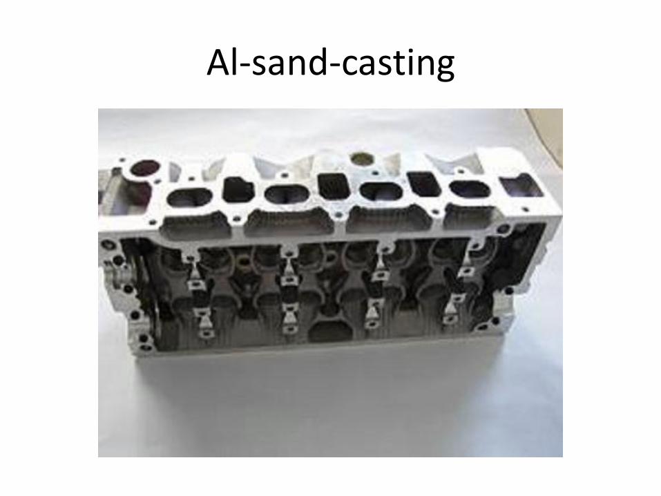
Al-sand-casting
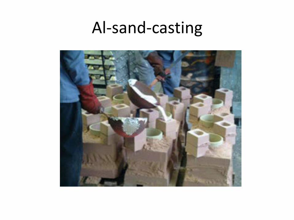
Al-sand-casting

Al-sand-casting
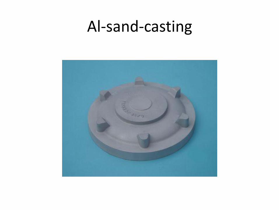
Al-sand-casting

Al-sand-casting

Al-sand-casting

Al-sand-casting

Al-sand-casting

Al-sand-casting
Al-sand-casting

Al-sand-casting

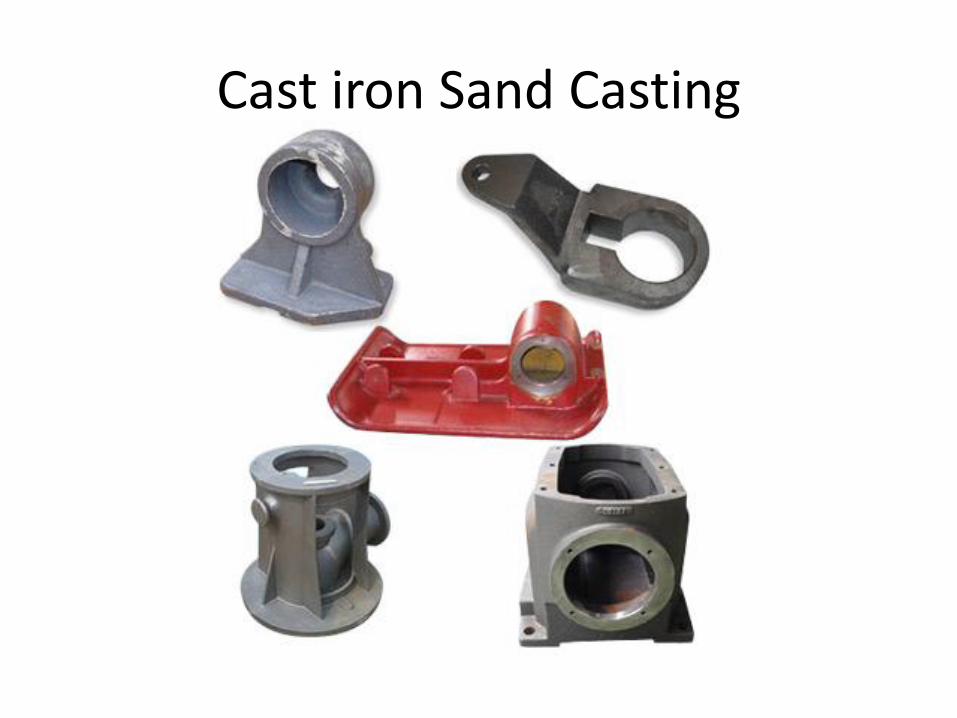
Cast iron Sand Casting
Cast iron Sand Casting

Cast iron Sand Casting