hilic practical guide
TRANSCRIPT

A Practical Guide to HILIC including ZIC®-HILIC applications
SeQuant™
Merck KGaA64271 Darmstadt, GermanyFax + 49 (0) 61 51 /72 - 60 80E-mail: chromatography@merck.dechromatography.merck.dewww.mercksequant.comwww.merck-chemicals.com
We provide information and advice to our customers on application technologies and regulatory matters to the best of our knowledge and ability, but without obligation or liability. Existing laws and regulations are to be observed in all cases by our customers. This also applies in respect to any rights of third parties. Our information and advice do not relieve our customers of their own responsibility for checking the suitability of our products for the envisaged purpose. ZIC® is a registered trademark of Merck KGaA, Darmstadt, Germany.
W28
8112
IS
BN 9
78-9
1-63
1-83
70-6
1s
t ed
ition
, 5th
issu
e
Including ZIC®-HILIC applications · 1
© Copyright, 2005-2008 , Merck SeQuant AB
A PRACTICAL GUIDE TO HILIC
Including ZIC®-HILIC applications

2 · A Practical Guide to HILIC
http://www.mercksequant.com
A Practical Guide to HILIC
ISBN 978-91-631-8370-6
Authors: Patrik Appelblad, Tobias Jonsson, Einar Pontén, Camilla Viklund and Wen Jiang
Editor: Tobias Jonsson
Published by Merck SeQuant AB, Box 7956, 907 19 Umeå, Sweden.
Copyright © 2005-2008, Merck SeQuant AB
1:st edition. 5:th issue. Printed at Original, Umeå, Sweden, November 2008.
Revisions and additional material can be found on Merck SeQuant’s website (www.mercksequant.com). Questions and comments regarding the content in this booklet can be e-mailed to [email protected].
© Copyright, 2005-2008 , Merck SeQuant AB
A PRACTICAL GUIDE TO HILIC Including ZIC®-HILIC applications
Introduction
This guide aims at introducing hydrophilic interaction liquid chromatography (HILIC), which is a technique suitable for separation of very polar and hydrophilic compounds. It deals with the basic theory of HILIC and the practical aspects of this separation mode. This booklet will also introduce the reader to the Merck SeQuant™ zwitterionic ZIC®-HILIC and ZIC®-pHILIC stationary phases, see Figure 1, and contains a range of application examples for different types of hydrophilic compounds. You can read more about this and lots of other things in this guide.
Figure 1: The functional group of the ZIC®-HILIC and ZIC®-pHILIC stationary phases.
If your HILIC questions cannot be solved with this compilation Merck SeQuant™ is at your service. We first recommend you to visit the Merck SeQuant™ homepage (www.mercksequant.com), where you always find material update, applications and technical data on our products. If you need additional information the Merck SeQuant™ staff will be happy to further assist you.
Why HILIC?
Despite the fact that reversed phase liquid chromatography (RPLC) is the overall most applied separation technique, and that it can be used for a variety of applications in junction with the most common detection principles, certain solutes, especially polar and hydrophilic compounds, are not retainable in a simple fashion. Over a long period normal phase liquid chromatography (NPLC) has been the technique
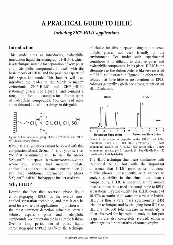
of choice for this purpose, using non-aqueous mobile phases not very friendly to the environment. Yet, under such experimental conditions it is difficult to dissolve polar and hydrophilic compounds. In its place, HILIC is the alternative as the elution order is likewise inverted to RPLC, as illustrated in Figure 2. In other words, solutes that have little or no retention on RPLC columns generally experience strong retention on HILIC columns.
Figure 2: Separation of peptides under HILIC and RPLC conditions. Eluents; (HILIC) 60:40 acetonitrile / 10 mM ammonium acetate, pH 7, (RPLC) 5:95 acetonitrile / 10 mM ammonium acetate, pH 7. Legend; (1) Phe-Gly-Gly-Phe, (2) Leu-Gly-Gly, (3) Gly-Gly-Gly.
The HILIC technique thus bears similarities with traditional NPLC, but with the important difference that HILIC employs semi-aqueous mobile phases. Consequently, with respect to analyte solubility in the eluent and matrix compatibility, HILIC is superior, as the mobile phase compositions used are comparable to RPLC separations. Typical eluents for HILIC consist of 40-97% acetonitrile in water or a volatile buffer. HILIC is thus a very mass spectrometry (MS) friendly technique, and by changing from RPLC to HILIC a 10-1000 fold increase in sensitivity is often observed for hydrophilic analytes. Ion-pair reagents are also completely avoided, which is advantageous for preparative chromatography.
4 · A Practical Guide to HILIC
http://www.mercksequant.com
The chromatographic system
A HILIC separation system is essentially instrumentally identical to RPLC systems. Because of the similarities to RPLC in mobile phase conditions, it can be tempting to apply the same routines for preparation of, for example, samples and wash solutions also for HILIC. This will definitively lead to problems for the chromato-grapher. The succeeding sections therefore treat the most critical parts of the HILIC separation system and contain guidelines for its successful operation while describing the theories behind the advices.
The column
HILIC columns contain a stationary phase that is hydrophilic and quite often also charged, at least in some region of the pH-scale. Compounds separating on the column interact with the stationary phase, and is generally more strongly retained the more hydrophilic the compound is. Unlike most other chromatographic techniques, part of the mobile phase is an integral part of the stationary phase (as outlined below), wherefore it is crucial to keep the water concentration in the eluent within certain limits. Typically the water fraction should be ~3-60%.
HILIC retention characteristics
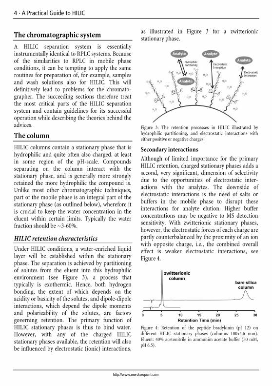
Under HILIC conditions, a water-enriched liquid layer will be established within the stationary phase. The separation is achieved by partitioning of solutes from the eluent into this hydrophilic environment (see Figure 3), a process that typically is exothermic. Hence, both hydrogen bonding, the extent of which depends on the acidity or basicity of the solutes, and dipole-dipole interactions, which depend the dipole moments and polarizability of the solutes, are factors governing retention. The primary function of HILIC stationary phases is thus to bind water. However, with any of the charged HILIC stationary phases available, the retention will also be influenced by electrostatic (ionic) interactions,
as illustrated in Figure 3 for a zwitterionic stationary phase.
Figure 3: The retention processes in HILIC illustrated by hydrophilic partitioning, and electrostatic interactions with either positive or negative charges.
Secondary interactions
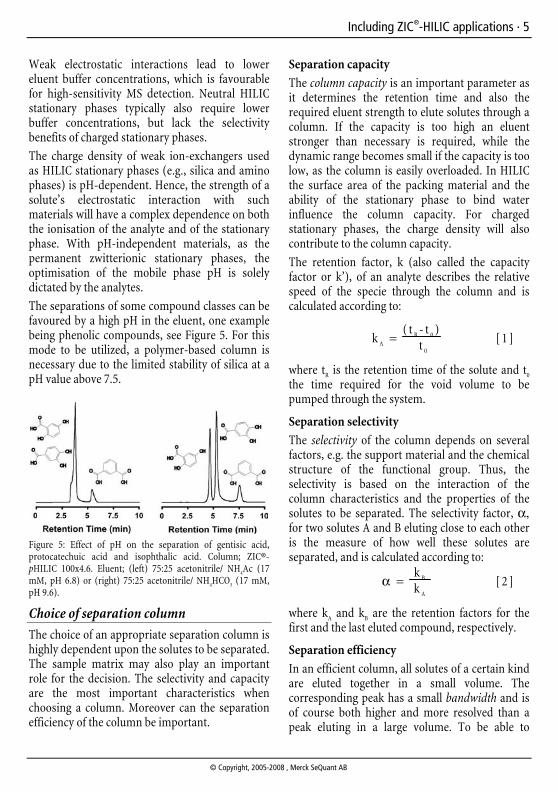
Although of limited importance for the primary HILIC retention, charged stationary phases adds a second, very significant, dimension of selectivity due to the opportunities of electrostatic inter-actions with the analytes. The downside of electrostatic interactions is the need of salts or buffers in the mobile phase to disrupt these interactions for analyte elution. Higher buffer concentrations may be negative to MS detection sensitivity. With zwitterionic stationary phases, however, the electrostatic forces of each charge are partly counterbalanced by the proximity of an ion with opposite charge, i.e., the combined overall effect is weaker electrostatic interactions, see Figure 4.
Figure 4: Retention of the peptide bradykinin (pI 12) on different HILIC stationary phases (columns 100x4.6 mm). Eluent: 40% acetonitrile in ammonim acetate buffer (50 mM, pH 6.5).
Including ZIC®-HILIC applications · 5
© Copyright, 2005-2008 , Merck SeQuant AB
Weak electrostatic interactions lead to lower eluent buffer concentrations, which is favourable for high-sensitivity MS detection. Neutral HILIC stationary phases typically also require lower buffer concentrations, but lack the selectivity benefits of charged stationary phases.
The charge density of weak ion-exchangers used as HILIC stationary phases (e.g., silica and amino phases) is pH-dependent. Hence, the strength of a solute’s electrostatic interaction with such materials will have a complex dependence on both the ionisation of the analyte and of the stationary phase. With pH-independent materials, as the permanent zwitterionic stationary phases, the optimisation of the mobile phase pH is solely dictated by the analytes.
The separations of some compound classes can be favoured by a high pH in the eluent, one example being phenolic compounds, see Figure 5. For this mode to be utilized, a polymer-based column is necessary due to the limited stability of silica at a pH value above 7.5.
Figure 5: Effect of pH on the separation of gentisic acid, protocatechuic acid and isophthalic acid. Column; ZIC®-pHILIC 100x4.6. Eluent; (left) 75:25 acetonitrile/ NH4Ac (17 mM, pH 6.8) or (right) 75:25 acetonitrile/ NH4HCO3 (17 mM, pH 9.6).
Choice of separation column
The choice of an appropriate separation column is highly dependent upon the solutes to be separated. The sample matrix may also play an important role for the decision. The selectivity and capacity are the most important characteristics when choosing a column. Moreover can the separation efficiency of the column be important.
Separation capacity
The column capacity is an important parameter as it determines the retention time and also the required eluent strength to elute solutes through a column. If the capacity is too high an eluent stronger than necessary is required, while the dynamic range becomes small if the capacity is too low, as the column is easily overloaded. In HILIC the surface area of the packing material and the ability of the stationary phase to bind water influence the column capacity. For charged stationary phases, the charge density will also contribute to the column capacity.
The retention factor, k (also called the capacity factor or k’), of an analyte describes the relative speed of the specie through the column and is calculated according to:
k A = ( t R - t 0 )
t 0
[ 1 ]
where tR is the retention time of the solute and t0 the time required for the void volume to be pumped through the system.
Separation selectivity
The selectivity of the column depends on several factors, e.g. the support material and the chemical structure of the functional group. Thus, the selectivity is based on the interaction of the column characteristics and the properties of the solutes to be separated. The selectivity factor, α, for two solutes A and B eluting close to each other is the measure of how well these solutes are separated, and is calculated according to:
α = k B k A [ 2 ]
where kA and kB are the retention factors for the first and the last eluted compound, respectively.
Separation efficiency
In an efficient column, all solutes of a certain kind are eluted together in a small volume. The corresponding peak has a small bandwidth and is of course both higher and more resolved than a peak eluting in a large volume. To be able to
6 · A Practical Guide to HILIC
http://www.mercksequant.com
compare columns, the retention time of the peak also has to be considered. The efficiency expressed as the number of theoretical plates is written:
N = 5 . 5 4 ⎝⎛
⎠⎞ t R
w ½
2
[ 3 ]
where w1/2 is the peak width at half of the peak height. The determining factor for the efficiency of the column is the number of occasions that the solute can interact with the separation material during its transport through the column. The number of interactions is called “plates”, according to a terminology taken from the theory of distillation. High plate numbers are achieved when the solutes only have to be transported short distances through the eluent and the stagnant aqueous layer within the stationary phase for every new establishment of the distribution equilibrium between the mobile and the stationary phases.
Decreased efficiency with a large void volume
The void volume, also referred to as the dead volume, is the total volume of liquid between the injector and the detector. The size of the void volume determines the time (t0) for a compound that is not retained on the separation material, to reach the detector. The void volume (Vvoid or V0) is the sum of the volume inside and outside the column:
V 0 = Vv o i d= Vc o l u m n+ Ve x t r a [ 4 ]
The void volume of the column (Vcolumn) is the volume between and within the pores of the individual particles, which in total form the packing material of the column. For a fixed column size, the column void volume is practically constant and independent of the diameter of the packed particles. An important source of band-broadening is, however, the volume outside the column (Vextra), i.e. the volume in the injection loop, the interconnecting tubing, and the detector. All tubing used to connect the components of the system should be short, while having the smallest possible inner diameter, to minimize the band-
broadening and not to destroy the efficiency obtained by a high quality column. Of course the decrease of tubing’s inner diameter is limited, as the backpressure and the risk of unintentional clogging increases accordingly.
Minimize the void volume by keeping all flow paths as short as possible!
Also note that the volume between the pump and the injector is of no importance to the band-broadening, but it can nevertheless be impractical, since the change of eluent might take unnecessary long time.
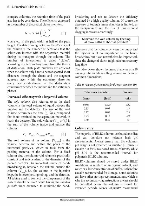
The table below shows the inner diameter of a 10 cm long tube and its resulting volume for the most common dimensions.
Table 1: Volume of 10 cm tubes for the most common IDs.
Tube inner diameter Volume
(mm) (inch) (µL)
0.064 0.025 0.32 0.13 0.05 1.3 0.17 0.07 2.3 0.25 0.10 4.9 0.50 0.20 20
Column care
The majority of HILIC columns are based on silica and can therefore not tolerate high pH environments. Always ensure that the column’s pH range is not exceeded. A suitable pH range is usually 3-8 for silica-based HILIC columns, while pH 2-10 is the recommended interval for polymeric HILIC columns.
HILIC columns should be stored under HILIC conditions. A mixture of an organic solvent, and water or a low concentration of buffer, is therefore usually recommended for storage. Some columns can have other storing recommendations, which is why the accompanying instructions always should be consulted before the column is stored for extended periods. Merck SeQuant™ recommend
Including ZIC®-HILIC applications · 7
© Copyright, 2005-2008 , Merck SeQuant AB
that the ZIC®-HILIC and ZIC®-pHILIC columns are stored as shipped, i.e. in:
• 80:20 acetonitrile / NH4Ac 5 mM, pH 6.8
Column regeneration
A HILIC column that starts showing signs of poor separation with lower efficiency (broader peaks), altered retention times and deviations in the calibration curves, may have lost capacity due to strong binding of crud (chromatographically retained undesired debris) to the stationary phase. If high backpressure develops over the column it is usually because some of the matrix components have precipitated and clogged the inlet frit.
Usually the function can be partly restored by rinsing the column with a strong buffer or salt solution at low flow rates in the reverse direction. During this procedure it is important to connect the column outlet directly to waste. Merck SeQuant™ recommends the following wash procedure for column regeneration and removal of precipitates, but note that other manufacturers can have different recommendations.
• 30 column volumes of deionised water
• 30 column volumes of 0.5 M NaCl
• 30 column volumes of deionised water
If it is undesirable to use NaCl, an alternative approach is to apply a standard buffer salt at the same concentration, e.g. ammonium acetate 0.5 M.
The mobile phase
As stated previously, typical eluents for HILIC consist of 40-97% acetonitrile in water or a volatile buffer. To obtain reproducible results, at least 3% water should be maintained in the mobile phase. This amount of water is necessary in order to ensure sufficient hydration of the stationary phase particles. In addition, remember that, a higher concentration of organic solvent in the mobile phase will increase the retention.
Higher organic solvent in the eluent increases the retention of the solutes.
Several polar, water-miscible organic solvents are possible to use in HILIC, although acetonitrile is by far the most popular. The solvent strength is roughly inverted to what is observed for RPLC separations, and the relative solvent strength can be outlined as:
• Acetone < acetonitrile < iso-propanol < ethanol < methanol < water
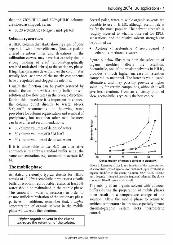
Figure 6 below illustrates how the selection of organic modifier affects the retention. Acetonitrile, one of the weaker solvents in HILIC, provides a much higher increase in retention compared to methanol. The latter is yet a usable alternative, and may possibly provide a higher solubility for certain compounds, although it will give less retention. From an efficiency point of view, acetonitrile is typically the best choice.
Figure 6: Retention factor k as a function of the concentration of acetonitrile (closed symbols) or methanol (open symbols) as organic modifier in the eluent. Column; ZIC®-HILIC 150x4.6 mm. Legend; (triangles) cytosine (squares) adenine. The eluent contained 10 mM formic acid overall.
The mixing of an organic solvent with aqueous buffers during the preparation of mobile phases often result in a temperature change of the solution. Allow the mobile phase to return to ambient temperature before use, especially if your chromatographic system lacks thermostatic control.
8 · A Practical Guide to HILIC
http://www.mercksequant.com
Buffer recommendations
Suitable buffers for HILIC are ammonium salts of acetate and formate, but also formic and acetic acids are recommended, all due to excellent solubility even in very high concentrations of organic solvent. Phosphates and other low solubility buffers should be used with caution or be avoided to prevent precipitation, although they typically are associated with higher UV-detection sensitivity. Ammonium hydroxide and ammonium carbonate are suitable alternatives when a high pH is desired. A buffer concentration in the range 5-20 mM is sufficient for most solutes, with an upper limit of 200-300 mM, depending on the solubility in the eluent. Negatively or positively charged stationary phases typically require higher buffer concentrations than neutral or zwitterionic stationary phases. TFA and other ion pair reagents should be avoided, as they can both interfere with the HILIC mechanism, but also suppress MS signals. A suitable pH range is 3-8 for most silica-based HILIC columns, while pH 2-10 usually is the recommended interval for polymeric HILIC columns.
Degassing
The mobile phase should preferably be degassed daily, to avoid pump related interferences and to lower detector noise. If your chromatographic system lacks an online degassing device, purging a stream of inert gas, i.e. helium, through the eluent directly in its storing container is sufficient. Helium is the gas of choice as it has a very low solubility in the mobile phase.
Filtration
The mobile phase should also be filtered before use, preferably through a filter with 0.45 µm porosity. This preventive step prolongs the column lifetime and also protects the pump from damage. Choose a hydrophilic filter based on poly(tetrafluoroethylene) (PTFE), poly(vinyliden-difluoride) (PVDF) or similar chemically inert material.
Isocratic elution and gradient elution
In liquid chromatography, the most common type of elution is isocratic, i.e. where the eluent has a constant concentration and composition during the entire run.
Gradient elution in HILIC is accomplished by increasing the polarity of the mobile phase, by decreasing the concentration of organic solvent, i.e. in the “opposite” direction compared to RPLC separations. With charged HILIC stationary phases there is also a possibility of increasing the salt or buffer concentration during a gradient to disrupt electrostatic interactions with the solute.
Gradient elution is basically used to separate solutes with widely different retention factors (capacity factors) during the same run with good separation efficiency and tolerable retention times. After a gradient run the column has to be equilibrated with the starting concentration of the mobile phase before the next sample can be injected.
It must be emphasized that HILIC stationary phases are less tolerable to fast gradients and short equilibrium times compared to RPLC phases. This is because the water in the aqueous layer within the stationary phase originates from the eluent and therefore is depending on its composition. A HILIC gradient should not be run from 100% organic to 100% aqueous for the same reasons. It is also worth mentioning that the column back-pressure will increase during the gradient if low-viscosity solvents as acetonitrile are used.
Do not run HILIC gradients from 100% organic to 100% aqueous!
Failure to properly equilibrate HILIC columns will cause drifting retention times and poor reproducibility. In some cases, however, it is possible to reach a dynamic equilibrium with stable retention times if fast gradients are run repeatedly for a longer period of time, but this situation can be tricky to obtain and reproduce.
Including ZIC®-HILIC applications · 9
© Copyright, 2005-2008 , Merck SeQuant AB
Typical elution protocols
Suitable starting conditions for upcoming optimisation and method development work are listed below. These conditions are recommended for the SeQuant™ ZIC®-HILIC and ZIC®-pHILIC stationary phases but can apply to other HILIC phases as well with some modifications (like higher salt concentrations with charged phases):
• Isocratic elution: 80:20 (v/v) acetonitrile/ ammonium acetate or formic acid (20 mM)
• Gradient elution: A linear gradient from 90% to 40% acetonitrile in ammonium acetate buffer (20 mM) in ~20 minutes (slope ~3% min-1). An equilibrium time of 10 minutes is advised
The injector
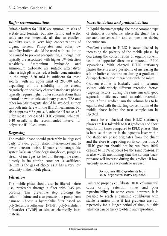
By varying the size of the injection loop in the injector, the amount of sample introduced to the column can be changed. Injection volumes ranging from 1 to 100 µL are commonly used, for guidelines see Table 2. Injection of excessive sample volumes will cause volume overload that significantly will decrease the separation efficiency. In extreme cases a volume overload can give flattened peaks, as illustrated in Figure 7. When injecting fixed volumes, minimum band-broadening is obtained when a long tube with a small inner diameter is used as injection loop. In a tube with a laminar flow, the dispersion is proportional to the square root of the length and the square of the tube radius respectively. This is why a tube with a small inner diameter gives less band-broadening.
Table 2: Suitable injection volumes and flow rates for different column inner diameters.
Column ID Injection volume Flow rate
(mm) (µl) (mL min-1)
7.5 10-150 1.3 4.6 5-50 0.5 2.1 0.5-5 0.1
Figure 7: Overlay of chromatograms with increasing injection volume. Injection volumes; 3 µL, 20 µL and 200 µL. Column; 50x4.6 mm ID ZIC®-HILIC column with 5 µm particles. Sample; toluene, uracil and cytosine, diluted in mobile phase.
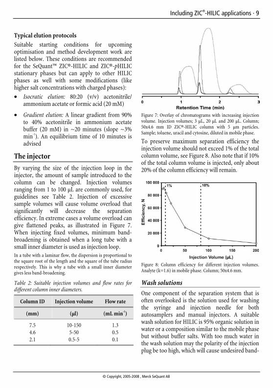
To preserve maximum separation efficiency the injection volume should not exceed 1% of the total column volume, see Figure 8. Also note that if 10% of the total column volume is injected, only about 20% of the column efficiency will remain.
Figure 8: Column efficiency for different injection volumes. Analyte (k=1.6) in mobile phase. Column; 50x4.6 mm.
Wash solutions
One component of the separation system that is often overlooked is the solution used for washing the syringe and injection needle for both autosamplers and manual injectors. A suitable wash solution for HILIC is 95% organic solution in water or a composition similar to the mobile phase but without buffer salts. With too much water in the wash solution may the polarity of the injection plug be too high, which will cause undesired band-

10 · A Practical Guide to HILIC
http://www.mercksequant.com
broadening. Pure organic solvents are normally not suitable either since they are not polar enough to remove the hydrophilic analytes that HILIC deals with.
Prevent contamination
Avoid rubber lids on sample vials and syringes with rubber gaskets as they notoriously release various basic and acidic compounds. To minimise carryover effects, also ensure that that the injection loop filling time and/or volume is adequately large for your autosampler. If manual injection performed, the loop should be rinsed with a volume at least 10 times the loop size. Also it is usually better to draw, rather than to push, the sample solution through the injection loop.
Sample pre-treatment
The need for sample pre-treatment is, to a large extent, affected by the sample matrix, i.e. the content of the sample except the solutes to be analysed. For HILIC separations it is important though that the sample is not in an environment that is too hydrophilic. If the injection plug contains too much water or another very hydrophilic solvent, the partitioning of the solutes into the stationary phase will be decreased. This will result in lower retention, poorer efficiency, and inferior separation, especially for the least retained compounds and if the injection volume is large. Aqueous samples should therefore usually not be injected directly, but preferably diluted with organic solvent to at least 50%.
Samples should not be diluted in water!
It is also recommended that samples be filtrated before injection. Suitable filters are hydrophilic PTFE or PVDF filters with a pore size of 0.45 µm.
Complementary SPE selectivity
The complementary selectivity of HILIC and RPLC can be used for efficient sample clean-up in the solid phase extraction (SPE) format. Samples enriched on and eluted from a RPLC SPE is usually rich in organic solvent and therefore suitable for
direct injection on a HILIC separation column without evaporation and reconstitution. In many cases the solution is hydrophobic enough to cause peak compression on the HILIC column. The opposite benefits can be gained by using HILIC SPE followed by a RPLC analytical separation. After a HILIC SPE treatment the final sample is eluted in a solution containing a large portion of water. This solution is then usually sufficiently aqueous to accomplish peak compression on the RPLC separation column.
ZIC®-HILIC and ZIC®-pHILIC
Merck SeQuant™ manufactures several featured HILIC products, including the zwitterionic ZIC®-HILIC and ZIC®-pHILIC stationary phases. The remainder of this booklet is devoted to the presentation of technical documentation and application examples for these products.
Figure 9: The functional group of the ZIC®-HILIC and ZIC®-pHILIC stationary phases.
The silica-based ZIC®-HILIC stationary phase carry a covalently bonded, permanently zwitter-ionic, functional group of the sulfobetaine type, see Figure 9. ZIC®-HILIC is available on 3.5, 5 and 10 µm particle sizes, in various column dimensions, where the column material is based on glass-lined stainless steel for capillary columns, PEEK and stainless steel for analytical columns, and stainless steel for preparative columns. The polymer-based ZIC®-pHILIC features the same sulfobetaine type zwitterionic functional group and is available on 5 µm polymer particles.
Including ZIC®-HILIC applications · 11
© Copyright, 2005-2008 , Merck SeQuant AB
Figure 10: Evaporative light scattering detector (ELSD) data on phase bleed of various column brands (Courtesy of Alltech Associates Inc.).
Both the ZIC®-HILIC and ZIC®-pHILIC stationary phases are designed for efficient HILIC separation of acidic basic and neutral hydrophilic compounds. In the design of these dedicated HILIC phases, special care has been taken to ensure low stationary phase bleed (see Figure 10) and a long column lifetime (see Figure 11).
Figure 11: Repeated injection of toluene (void marker), uracil and cytosine on a ZIC®-HILIC column 50x4.6 mm. Eluent; 80:20 acetonitrile/ NH4Ac (5 mM) with a flow rate of 0.5 mL/min.
Choice of separation column
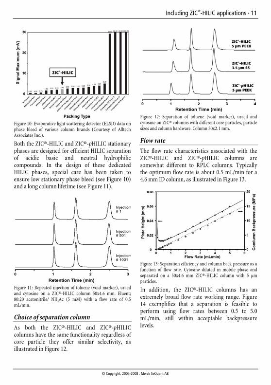
As both the ZIC®-HILIC and ZIC®-pHILIC columns have the same functionality regardless of core particle they offer similar selectivity, as illustrated in Figure 12.
Figure 12: Separation of toluene (void marker), uracil and cytosine on ZIC® columns with different core particles, particle sizes and column hardware. Column 50x2.1 mm.
Flow rate
The flow rate characteristics associated with the ZIC®-HILIC and ZIC®-pHILIC columns are somewhat different to RPLC columns. Typically the optimum flow rate is about 0.5 mL/min for a 4.6 mm ID column, as illustrated in Figure 13.
Figure 13: Separation efficiency and column back pressure as a function of flow rate. Cytosine diluted in mobile phase and separated on a 50x4.6 mm ZIC®-HILIC column with 5 µm particles.
In addition, the ZIC®-HILIC columns has an extremely broad flow rate working range. Figure 14 exemplifies that a separation is feasible to perform using flow rates between 0.5 to 5.0 mL/min, still within acceptable backpressure levels.

12 · A Practical Guide to HILIC
http://www.mercksequant.com
Figure 14: Overlay of chromatograms at different flow rates. Separation of toluene (void marker), uracil and cytosine, all diluted in mobile phase and separated on a 50x4.6 mm ZIC®-HILIC column with 5 µm particles.
Scalability
The analytical separation is often the basis for a scale-up procedure to semi-preparative, preparative, or industrial scale separations. The scalability downwards, to micro and nano dimensions becomes more and more popular as well. With the ZIC®-HILIC stationary phases, a seamless linear scale-up from analytical to semi-preparative and preparative, is easily achieved as illustrated in Figure 15. The corresponding downscale to micro and capillary columns is similarly trouble-free.
In preparative work, the mass loadability of the column is an important parameter. As exemplified in Figure 16, the ZIC®-HILIC columns show a comparably high mass loadability, despite the rather low retention factor in this example.
Figure 15: Separations scaled on columns with 50 mm length. Column; ZIC®-HILIC with 5 µm particles, except for the 20 mm ID column which had 10 µm particles.
Figure 16: Loadability of nicotinamide. The retention factor k was 0.65. Column; ZIC®-HILIC 150x20, 5µm. Eluent; 90% acetonitrile, 10% 5 mM ammonim acetate. Flow rate; 18.6 mL/min. Injection; 0.5 mL (1-100 mg/mL) in mobile phase.
Applications
The last pages of this booklet contain a range of example applications for the different ZIC®-HILIC and ZIC®-pHILIC products. The table below contains a complete list of the applications presented on the following pages.

Including ZIC®-HILIC applications · 13
© Copyright, 2005-2008 , Merck SeQuant AB
Table 3: A list of the ZIC®-HILIC and ZIC®-pHILIC applications presented in the remainder of this booklet.
Application Page
SPE - Amoxicillin in plasma 14 SPE – Digested proteins 15 LC – Purines and pyrimidines 16 LC – Nucleotides 17 LC – Peptides 18 LC – Tryptic digest 19 LC – Aliphatic amino acids 20 LC – Acrylamides 21 LC – Quaternary amines 22 LC – Dehydroascorbic acid and ascorbic acid 23 LC – Fumaric, oxalic and citric acids 24 LC– Homocysteine methylmalonic acid and succinic acid 25 LC – Morphine and glucuronated metabolites 26 LC – Flavanoids 27
14 · A Practical Guide to HILIC
http://www.mercksequant.com
SPE - Amoxicillin in plasma
Simple removal of interfering analytes and late eluting peaks
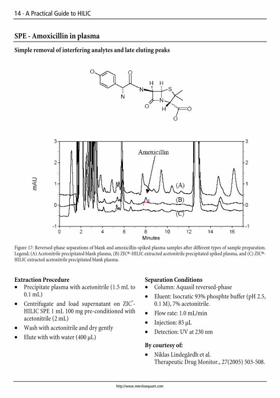
Figure 17: Reversed-phase separations of blank and amoxicillin-spiked plasma samples after different types of sample preparation. Legend; (A) Acetonitrile precipitated blank plasma, (B) ZIC®-HILIC extracted acetonitrile precipitated spiked plasma, and (C) ZIC®-HILIC extracted acetonitrile precipitated blank plasma.
Extraction Procedure • Precipitate plasma with acetonitrile (1.5 mL to
0.1 mL)
• Centrifugate and load supernatant on ZIC®-HILIC SPE 1 mL 100 mg pre-conditioned with acetonitrile (2 mL)
• Wash with acetonitrile and dry gently
• Elute with with water (400 µL)
Separation Conditions • Column: Aquasil reversed-phase
• Eluent: Isocratic 93% phosphte buffer (pH 2.5, 0.1 M), 7% acetonitrile.
• Flow rate: 1.0 mL/min
• Injection: 85 µL
• Detection: UV at 230 nm
By courtesy of:
• Niklas Lindegårdh et al. Therapeutic Drug Monitor., 27(2005) 503-508.
Including ZIC®-HILIC applications · 15
© Copyright, 2005-2008 , Merck SeQuant AB
SPE – Digested proteins
Micro solid phase extraction for identification of N-glycosylated proteins
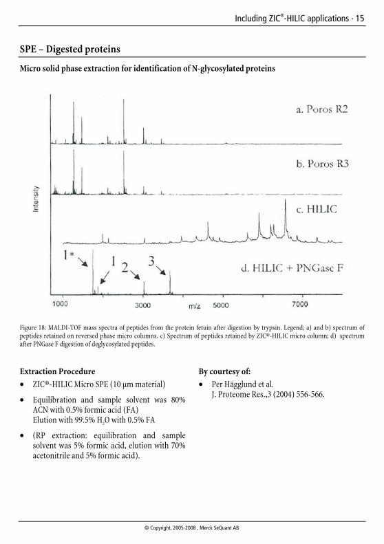
Figure 18: MALDI-TOF mass spectra of peptides from the protein fetuin after digestion by trypsin. Legend; a) and b) spectrum of peptides retained on reversed phase micro columns. c) Spectrum of peptides retained by ZIC®-HILIC micro column; d) spectrum after PNGase F digestion of deglycosylated peptides.
Extraction Procedure
• ZIC®-HILIC Micro SPE (10 µm material)
• Equilibration and sample solvent was 80% ACN with 0.5% formic acid (FA) Elution with 99.5% H2O with 0.5% FA
• (RP extraction: equilibration and sample solvent was 5% formic acid, elution with 70% acetonitrile and 5% formic acid).
By courtesy of:
• Per Hägglund et al. J. Proteome Res.,3 (2004) 556-566.

16 · A Practical Guide to HILIC
http://www.mercksequant.com
LC – Separation of purines and pyrimidines
HN
NH
O
O
HN
NH
O
O
N
N N
NH
NH2
N
N N
NH
O
H2N
HN
NH
NH2
O
Figure 19: Separation of thymine (1), uracil (2), adenine (3), guanine (4), and cytosine (5).
Chromatographic Data
Analyte tR (min) k α
void volume (t0) 3.2 - -
Thymine 4.7 0.5 - Uracil 5.3 0.7 3.9 Adenine 6.5 1.0 6.0 Guanine 8.4 1.6 5.2 Cytosine 12.9 3.0 5.6
Separation Conditions
• Column: ZIC®-HILIC 150 x 2.1 mm, 5 µm
• Eluent: 80% (v/v) acetonitrile; 20% (v/v) 25 mM acetic acid, 2.5 mM ammonium acetate
• Flow rate: 0.1 mL/min
• Detection: UV at 254 nm
• Injection: 2 µL in mobile phase

Including ZIC®-HILIC applications · 17
© Copyright, 2005-2008 , Merck SeQuant AB
LC – Separation of nucleotides
Figure 20: Complete separation of six adenosine phosphates
Chromatographic Data
Analyte tR (min) k α
void volume (t0) 2.5 - -
cAMP 4.3 0.7 - dAMP 6.2 1.5 2.1 AMP 7.2 1.9 1.3 ADP 9.5 2.8 1.5 dATP 10.9 3.4 1.2 ATP 13.3 4.3 1.3
Separation conditions • Column: ZIC®-pHILIC 150 x 4.6 mm, 5 µm
• Eluent: 70% (v/v) acetonitrile; 30% (v/v) 100 mM ammonium acetate, pH 8.8
• Flow rate: 0.5 mL/min
• Detection: UV at 254 nm
• Injection: 5 µL in mobile phase
• Sample: 45 µg/mL of AMP, cAMP and dAMP, 90 µg/mL of ADP, dATP and ATP

18 · A Practical Guide to HILIC
http://www.mercksequant.com
LC – Separation of peptides
Figure 21: Separation of angiotensin II , neurotensin , bradykinin, and Gly-His-Lys.
Chromatographic data
Analyte tR (min) k α
void volume (t0) 2.0 - -
Angiotensin II 2.7 0.4 - Neurotensin 3.6 0.8 2.2 Bradykinin 6.7 2.4 2.9 Gly-His-Lys 13.3 5.7 2.4
Separation conditions • Column: ZIC®-HILIC 100 x 4.6 mm, 5 µm
• Eluent: 50% (v/v) acetonitrile; 50% (v/v) 50 mM ammonium acetate, pH 6.8
• Flow rate: 0.5 mL/min
• Detection: UV at 254 nm
• Injection: 2 µL in mobile phase

Including ZIC®-HILIC applications · 19
© Copyright, 2005-2008 , Merck SeQuant AB
LC – Separation of a tryptic digest
/ 0/ 1/ 2/ 3/
Qdsdmshnm shld 'lhm(
Figure 22: Separation of tryptic digest of cytochrome c.
Experimental conditions
• Column: ZIC®-HILIC 150 x 3.0 mm, 5 µm
• Gradient: Linear 0-50% in 40 min of Eluent B
• Eluent A: 81%(v/v) acetonitrile; 19%(v/v), 15 mM KH2PO4 buffer, pH 4.5
• Eluent B: 30%(v/v) acetonitrile; 70%(v/v), 20 mM KH2PO4 buffer, pH 4.5
• Flow rate: 0.8 mL/min
• Detection: UV at 214 nm
• Injection: 20 µL
• Sample: Tryptic digest of cytochrome c prepared from 25 mg protein in 2.5 ml 0.1 M ammonium carbonate buffer, and diluted 1:1 with acetonitrile
20 · A Practical Guide to HILIC
http://www.mercksequant.com
LC – Separation of aliphatic amino acids
0 2 4 6 8 10
Retention Time (min)
1
2
3
System peak
H2NOH
O
OH
O
NH2
OH
O
NH2
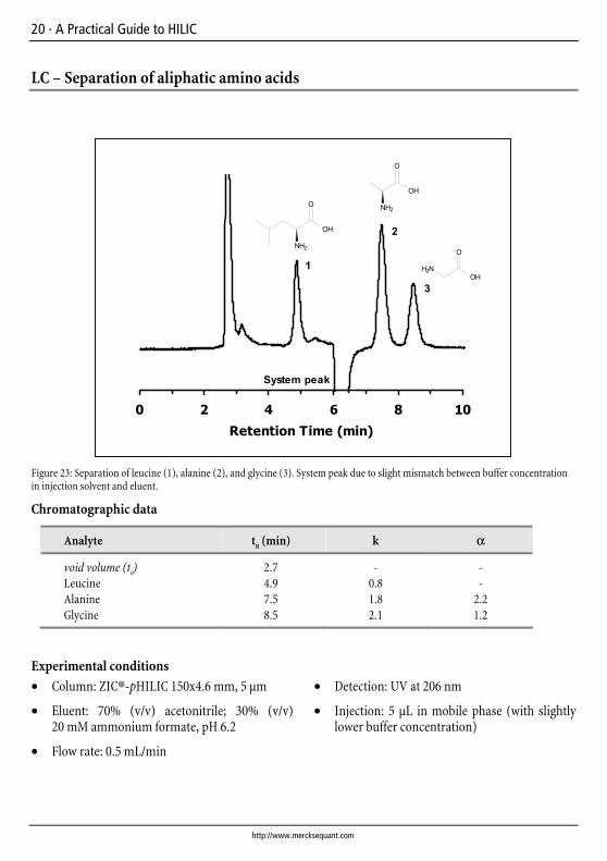
Figure 23: Separation of leucine (1), alanine (2), and glycine (3). System peak due to slight mismatch between buffer concentration in injection solvent and eluent.
Chromatographic data
Analyte tR (min) k α
void volume (t0) 2.7 - -
Leucine 4.9 0.8 - Alanine 7.5 1.8 2.2 Glycine 8.5 2.1 1.2
Experimental conditions
• Column: ZIC®-pHILIC 150x4.6 mm, 5 µm
• Eluent: 70% (v/v) acetonitrile; 30% (v/v) 20 mM ammonium formate, pH 6.2
• Flow rate: 0.5 mL/min
• Detection: UV at 206 nm
• Injection: 5 µL in mobile phase (with slightly lower buffer concentration)

Including ZIC®-HILIC applications · 21
© Copyright, 2005-2008 , Merck SeQuant AB
LC – Separation of acrylamides
NH2
O
NH2
O
O
OH
Figure 24: Separation of methacrylamide (1), acrylamide (2), and methacrylic acid (3).
Chromatographic data
Analyte tR (min) k α
void volume (t0) 1.5 - -
Methacrylamide 2.2 0.5 - Acrylamide 2.4 0.6 1.3 Methacrylic acid 2.6 0.8 1.2
Separation conditions
• Column: ZIC®-HILIC 150 x 4.6 mm, 5 µm
• Eluent: 95% (v/v) acetonitrile; 5% (v/v) 50 mM acetic acid
• Flow rate: 1.0 mL/min
• Detection: UV at 210 nm
• Injection: 5 µL in mobile phase
22 · A Practical Guide to HILIC
http://www.mercksequant.com
LC – Separation of quaternary amines
N+
ClN+
m/z 122
m/z 114
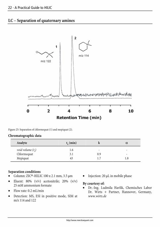
Figure 25: Separation of chlormequat (1) and mepiquat (2).
Chromatographic data
Analyte tR (min) k α
void volume (t0) 1.6 - -
Chlormequat 3.1 0.9 - Mepiquat 43 1.7 1.8
Separation conditions • Column: ZIC®-HILIC 100 x 2.1 mm, 3.5 µm
• Eluent: 80% (v/v) acetonitrile; 20% (v/v) 25 mM ammonium formate
• Flow rate: 0.2 mL/min
• Detection: MS, ESI in positive mode, SIM at m/z 114 and 122
• Injection: 20 µL in mobile phase
By courtesy of: • Dr.-Ing. Ludmila Havlik, Chemisches Labor
Dr. Wirts + Partner, Hannover, Germany, www.wirts.de
Including ZIC®-HILIC applications · 23
© Copyright, 2005-2008 , Merck SeQuant AB
LC – Separation of dehydroascorbic acid and ascorbic acid
0 2 4 6 8 10
Retention Time (min)
HO OH
O
HO
HO
O
OO
HO
OH
O O
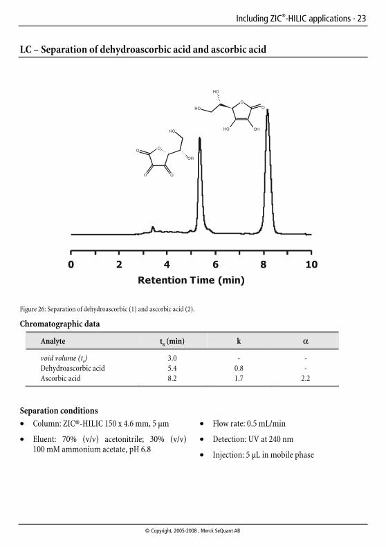
Figure 26: Separation of dehydroascorbic (1) and ascorbic acid (2).
Chromatographic data
Analyte tR (min) k α
void volume (t0) 3.0 - -
Dehydroascorbic acid 5.4 0.8 - Ascorbic acid 8.2 1.7 2.2
Separation conditions
• Column: ZIC®-HILIC 150 x 4.6 mm, 5 µm
• Eluent: 70% (v/v) acetonitrile; 30% (v/v) 100 mM ammonium acetate, pH 6.8
• Flow rate: 0.5 mL/min
• Detection: UV at 240 nm
• Injection: 5 µL in mobile phase
24 · A Practical Guide to HILIC
http://www.mercksequant.com
LC – Separation of fumaric, oxalic and citric acids
0 2 4 6 8 10
Retention Time (min)
HO
O
OH
O
OH
OH
O
HO
OHO
OOH
HO
O
O
1
2
3
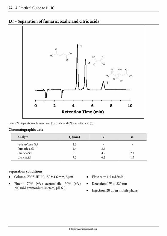
Figure 27: Separation of fumaric acid (1), oxalic acid (2), and citric acid (3).
Chromatographic data
Analyte tR (min) k α
void volume (t0) 1.0 - -
Fumaric acid 4.4 3.4 - Oxalic acid 5.3 4.2 2.1 Citric acid 7.2 6.2 1.5
Separation conditions
• Column: ZIC®-HILIC 150 x 4.6 mm, 5 µm
• Eluent: 70% (v/v) acetonitrile; 30% (v/v) 200 mM ammonium acetate, pH 6.8
• Flow rate: 1.5 mL/min
• Detection: UV at 220 nm
• Injection: 20 µL in mobile phase
Including ZIC®-HILIC applications · 25
© Copyright, 2005-2008 , Merck SeQuant AB
LC– Separation of homocysteine, methylmalonic acid and succinic acid
HO
O
OH
O
HO
O
OH
OHSOH
O
NH2
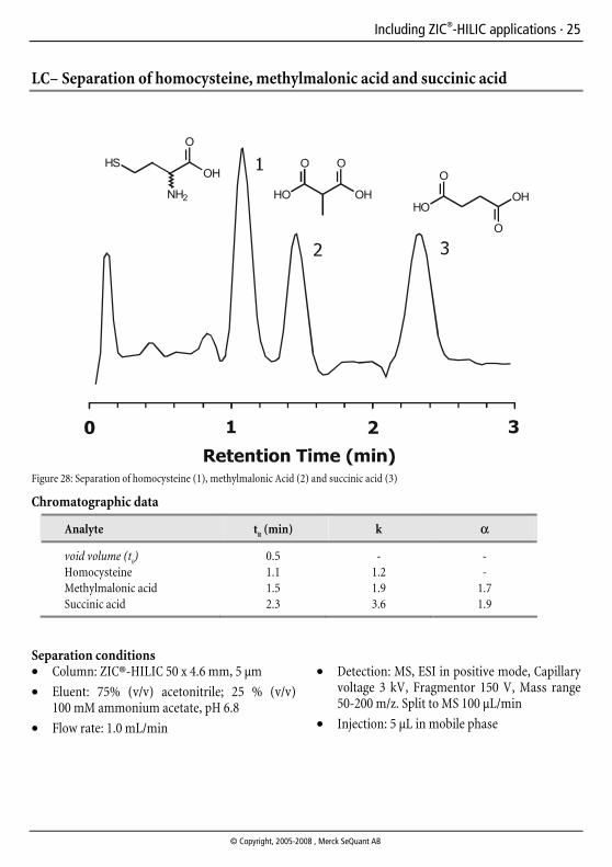
Figure 28: Separation of homocysteine (1), methylmalonic Acid (2) and succinic acid (3)
Chromatographic data
Analyte tR (min) k α
void volume (t0) 0.5 - -
Homocysteine 1.1 1.2 - Methylmalonic acid 1.5 1.9 1.7 Succinic acid 2.3 3.6 1.9
Separation conditions • Column: ZIC®-HILIC 50 x 4.6 mm, 5 µm
• Eluent: 75% (v/v) acetonitrile; 25 % (v/v) 100 mM ammonium acetate, pH 6.8
• Flow rate: 1.0 mL/min
• Detection: MS, ESI in positive mode, Capillary
voltage 3 kV, Fragmentor 150 V, Mass range 50-200 m/z. Split to MS 100 µL/min
• Injection: 5 µL in mobile phase
26 · A Practical Guide to HILIC
http://www.mercksequant.com
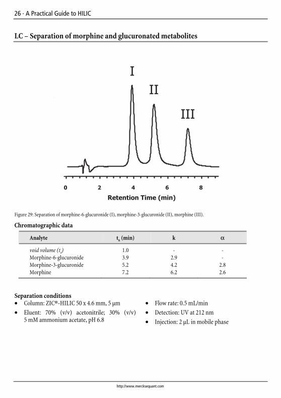
LC – Separation of morphine and glucuronated metabolites
Figure 29: Separation of morphine-6-glucuronide (I), morphine-3-glucuronide (II), morphine (III).
Chromatographic data
Analyte tR (min) k α
void volume (t0) 1.0 - -
Morphine-6-glucuronide 3.9 2.9 - Morphine-3-glucuronide 5.2 4.2 2.8 Morphine 7.2 6.2 2.6
Separation conditions • Column: ZIC®-HILIC 50 x 4.6 mm, 5 µm
• Eluent: 70% (v/v) acetonitrile; 30% (v/v) 5 mM ammonium acetate, pH 6.8
• Flow rate: 0.5 mL/min
• Detection: UV at 212 nm
• Injection: 2 µL in mobile phase
Including ZIC®-HILIC applications · 27
© Copyright, 2005-2008 , Merck SeQuant AB
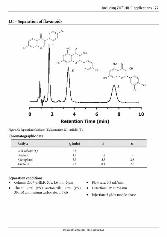
LC – Separation of flavanoids
O
OH
HO
O
O
OH
HO
HO O
OH
O
OH
HO
HO O
OH
OH
Figure 30: Separation of daidzen (1), kaempferol (2), taxifolin (3).
Chromatographic data
Analyte tR (min) k α
void volume (t0) 0.8 - -
Daidzen 1.7 1.2 - Kaempferol 3.5 3.3 2.8 Taxifolin 7.6 8.4 2.6
Separation conditions • Column: ZIC®-pHILIC 50 x 4.6 mm, 5 µm
• Eluent: 75% (v/v) acetonitrile; 25% (v/v) 30 mM ammonium carbonate, pH 9.6
• Flow rate: 0.5 mL/min
• Detection: UV at 254 nm
• Injection: 5 µL in mobile phase

28 · A Practical Guide to HILIC
http://www.mercksequant.com
Notes

A Practical Guide to HILIC including ZIC®-HILIC applications
SeQuant™
Merck KGaA64271 Darmstadt, GermanyFax + 49 (0) 61 51 /72 - 60 80E-mail: chromatography@merck.dechromatography.merck.dewww.mercksequant.comwww.merck-chemicals.com
We provide information and advice to our customers on application technologies and regulatory matters to the best of our knowledge and ability, but without obligation or liability. Existing laws and regulations are to be observed in all cases by our customers. This also applies in respect to any rights of third parties. Our information and advice do not relieve our customers of their own responsibility for checking the suitability of our products for the envisaged purpose. ZIC® is a registered trademark of Merck KGaA, Darmstadt, Germany.
W28
8112
IS
BN 9
78-9
1-63
1-83
70-6
1s
t ed
ition
, 5th
issu
e