highperformanceprecast - mapa precast primer... · precast primer . contents mapa producers, 2-3...
TRANSCRIPT

ef�cient ■ safe ■ resilienthighperformanceprecast

Page 1
Precast Primer
Contents
MAPA Producers, 2-3
Design Assistance, 4-6
Precast Overview, 7
High Performance Precast, 8-9
Architectural Precast, 10-12
Aesthetic Versatility, 13-15
Envelope Design, 16
Structural Precast, 17-20
Hollowcore Precast, 21-22
Specialty Precast, 23-24
Joint Design, 25
Construction Speed, 26
Design Economy, 27-28
Precast Resiliency, 29-30
Risk Management, 31
Precast Innovations, 32
Specifying Precast Concrete, 33-34
PCI Certification, 35
Resources, 36
Version 2: November 30, 2013

Page 2
Precast Primer
MAPA Producers
Brayman Precast
2900 South Noah Drive Saxonburg PA 16056
Phone: 724-352-5600
Website: http://www.braymanprecast.com
Contact: Ken DiBucci [email protected]
Concrete Building Systems
9283 Old Racetrack Road
P.O. Box 48 Delmar DE 19940
Phone: 302-846-3645 Fax: 302-846-0266
Website: http://www.cbs-incorp.com
Contact: Walt O’Day [email protected]
Conewago Precast Building Systems
660 Edgegrove Rd.
P.O. Box 407 Hanover, PA 17331
Phone: 717-632-7722 Fax: 717-632-5045
Website: http://www.conewago.com
Contact: Dan Eckenrode [email protected]
High Concrete Group, Inc.
125 Denver Road Denver PA 17517
Phone: 717-336-9300 Fax: 717-336-9301
Website: http://www.highconcrete.com
Contact: KellyTetkoskie [email protected]
Jersey Precast Corporation
853 Nottingham Road Hamilton Township NJ 08638
Phone: 609-689-3700 Fax: 609-689-3797
Website: http://www.jerseyprecast.com
Bridge Products: Arch Bridges
Markets: Bridges & Transportation
Contact: Paul Dentel [email protected]
Metromont Corporation
1650 Darbytown Road Richmond VA 23231
Phone: 804-222-6770
Website: http://www.metromont.com
Contact: Robbie Nesmith [email protected]
Eric Denny [email protected]
Newcrete Products - A Division of New Enterprise
Stone & Lime Co.
8180 Woodbury Pike Roaring Spring PA 16673
Phone: 814-224-2121 Fax: 610-625-8268
Website: http://www.newcrete.com
Contact: Dennis F. Campbell [email protected]
Northeast Prestressed Products LLC
121 River Street Cressona, PA 17929
Phone: 570-385-2352 Fax: 570-385-5898
Website: http://www.nppbeams.com
Contact: Lori Koury [email protected]

Page 3
Precast Primer
MAPA Producers
Oldcastle Precast Building Systems
1401 Trimble Road Edgewood MD 21040
Phone: 800-523-3747 Fax: 410-612-1214
Website: http://www.oldcastlesystems.com
Contact: Monica Schultes [email protected]
The Shockey Precast Group
P.O. Box 2530 Winchester VA 22604
Phone: 540-667-7700 Fax: 540-665-3272
Website: http://www.shockeyprecast.com
Contact: Jason Reynolds [email protected]
Slaw Precast
438 Riverview Road Lehighton, PA 18235
Phone: 610-852-2020 Fax: 610-852-2098
Website: http://www.slawprecast.com
Contact: Bob Slaw [email protected]
Tindall Corporation - Virginia
P.O. Box 711 Petersburg VA 23804
Phone: 804-861-8447 Fax: 804-862-6353
Website: http://www.tindallcorp.com
Contact: Steve Zivkovic [email protected]
Universal Concrete Products Corporation
400 Old Reading Pike, Suite 100
Stowe PA 19464
Phone: 610-323-0700
Fax: 610-323-4046
Website: http://www.universalconcrete.com
Contact: Elizabeth Strohl [email protected]
U.S. Concrete Precast Group
3369 Paxtonville Road Middleburg PA 17842
Phone: 570-837-1774 Fax: 570-837-1184
Website: http://www.us-concreteprecast.com
Contact: Steve Kenepp [email protected]

Page 4
Precast Primer
Design Assistance In recent years, a trend toward early integration of the design-
build process has created a Design-Assist process. It allows pre-
casters to respond to client’s escalating demands for faster, more
environmentally friendly construction and unified delivery with
less risk of price escalation. Meeting these demands requires ear-
ly and intense collaboration among the building team.
The architectural or structural precast concrete producer is selected based on its ability to:
execute the specific project’s demands
provide product and erection quality assurance through PCI Certification
demonstrate the capability for the technical expertise needed by the design and construction team.
Significant benefits can be achieved if the contract also includes the supply and installation of the final products. Estab-
lishing the design relationship as early in the contract with the precaster will significantly improve the outcome of the
project. Including the supply and installation of the final product along with the design assistance would only further
the overall project success.
Benefits of design assist include:
Development of concrete mixtures and finishes during the development process rather than going through a sam-ple approval process after bid and award.
Early, dependable, budget and schedule input from the precast supplier.
Reduction of requests for information (RFIs) with the precast supplier participating with the design team.
Preparation of erection drawings upon award of contract to the precaster, as well as creating a review process for shop drawings.
Close coordination of the supporting and bracing structural system for the precast panel connections with the engineer of record.
Efficient delivery and installation of precast concrete components due to close coordination between the con-struction schedule and the precast concrete production schedule.
Earlier coordination of every activity that typically occurs in a bid-build delivery process after the award.
Precasters’ detailed expertise provides expedited development of the design, with engineering innovations and scheduling improvements, while enhancing aesthetics and controlling budgets from conceptual design to project
completion. Each element can maximize its cost effectiveness by taking advantage of precast concrete’s inherent performance char-acteristics.
To maximize the potential, these elements should be considered:
Color and finish selection
Mold fabrication
Casting and finishing techniques
Handling methods in plant and at site
Connection concepts
Locations of connections to structure
Material costs
Construction sequencing

Page 5
Precast Primer
Design Assistance Throughout the process, the precaster should be considered as a partner on the
design team. This will impose a responsibility on the precaster to understand relat-
ed construction materials that must interface with the precast concrete so details appropriate to all the materials can
be developed.
The Design Assist process consists of four key components. The precaster can inform the design team when a specific
precast concrete-related design decision should be made to maximize efficiency in the production process.
Schematic Design (SD)
The precast technical representative requires specifics about the design intent regarding aesthetics and functionality. These should include:
Finishes desired and schedule of initial samples
Massing of volume and aesthetic elements
Load-bearing options or framing options
Insulation values for panels
Bay spacing and floor-to-floor heights
Panel-size limitation and repetition capability
Panel set-backs
Schedule
Budget limitations
Other design requirements (fire ratings, seismic design, blast
resistance, etc.)
Delivery requirements (time restrictions, building access, site
restraints, etc.)
Erection requirements (crane positioning, staging areas, etc.)
The schematic-design phase reviews options and finds the
approach that best leverages the benefits of architectural pre- cast concrete in an aesthetically appropriate, functional, and cost-effective manner.
Design Development (DD)
Based on the choices from the schematic-design phase, further refinement is accomplished in the design-development
phase. Issues to be addressed comprise:
Preliminary selections of color and texture for the exterior aesthetics.
Selection between loadbearing and structure-supported panels.
Consideration of a total-precast concrete structural framing system.
Decision on using insulated architectural precast concrete panels.
Final panelization scheme.
Review of repetition patterns to determine final mold costs.

Page 6
Precast Primer
Design Assistance Delineation of special aesthetic requirements (multiple colors and finishes,
special shapes, window setbacks, ornamental pieces, thin-brick embedment, stone attachments, etc.)
Coordination of the structural design scheme with the overall building design, including locations of panel con-nections and preliminary connection forces.
Selection of interior finishes (as they impact connection details).
Evaluation of vertical stiffness of structural components supporting panels.
Explanation of jobsite activity requirements and necessary coordination.
Construction Documents (CDs)
In the Design Assist role, the precaster can confirm refinements of and additions to architectural elevations, sections, and dimensions to en-sure they are in accord with earlier decisions and cost estimates.
The precaster will provide erection drawings and related calculations showing the loads and final forces from the connections to the struc-tural frame and the connection load locations. The architectural draw-ings are completed in this phase. Details specific to the precast con-crete may be completed on the precast-erection drawings rather than being incorporated into the architectural drawings. Interfacing details with adjacent materials such as glazing or other façade materials still have to be included in the architectural drawings so the other trades can be informed of the intended detailing.
Construction Administration (CA)
Product fabrication, delivery, and installation take place during this phase. The precaster’s role in this process includes:
Arranging plant visitations by the project team to ensure the de-sired color, texture, and quality conditions are achieved.
Preparation of mock-up panel(s) for approval by the owner or design professional
Conducting job-site visits and participation in project meetings to ensure smooth operations.
Monitoring installation and modifications to field conditions.
Coordinating all handling and erection details.
Creating a sequencing plan of erection components with the general contractor.
Maintaining close contact with firms transporting and erecting precast concrete components (if not done by the precaster directly).
Monitoring tolerances and alignment issues during installation.
Addressing and closing out the design team’s punch list.
Proposing a program of inspection and maintenance.
Successfully executing a well-planned Design-Assist process ensures all project complexities have been discussed and resolved early in design and planning. This process can eliminate expensive modifications during construc-tion.
The benefits to the owner and design team are a cost-effective design with a time- and money-saving schedule along with optimum product quality and appearance.

Page 7
Precast Primer
Precast Overview Precast Concrete Basics
Precast concrete consists of concrete (a mixture of cement, water, ag-
gregates and admixtures) cast into a specific shape at a location other
than its in-service position. The concrete is poured into a form, typical-
ly wood or steel, and cured before being stripped from the form, usual-
ly the following day due to high early strength additives. The compo-
nents are then transported to the construction site for erection.
The components are reinforced with either conventional reinforcing
bar or are prestressed with high-tensile strength strands that are pre-
tensioned in the form before the concrete is poured. Once the con-
crete has cured to a specific strength, the strands are cut
(detensioned). As the strands attempt to regain their original un-
tensioned length, they compress the bonded concrete, creating a com-
pressive force. This “precompression” adds load-carrying capacity to
the components and helps prevent and control cracking to specified
limits allowed by building codes.
Key Components
Precast concrete components can be used in a multitude of ways to help design any type of structure. Key precast con-
crete components are:
wall panels, which can include an enclosed layer of insulation sandwiched between interior and exterior wythes of
concrete. The interior finished face can also be designed to building structural support loads;
spandrels, which generally span between columns and can be used in conjunction with glazing or curtain wall sys-
tems on various building types;
column covers, which often are used to provide a
decorative architectural finish to structural columns in
high-profile locations;
double tees, so named due to the two extending
stems perpendicular to the horizontal deck. These tees
often are used for parking structures and buildings
where long open spans are desired;
hollowcore planks, which are long slabs in which
voids run the length of the pieces, reducing weight
without reducing the structural integrity;
structural pieces, including columns and a variety
of beam shapes;

Page 8
Precast Primer
High Performance Precast What is High Performance Precast Concrete?
High-performance buildings are becoming essential to meet the in-creasing variety of owner demands, from economic to environmental to safety. Precast concrete can help designers meet these needs for high performance in a multitude of ways.
The United States Federal Government, in the Energy Independence and Security Act of 2007(401 PL 110-140) defines a high-performance struc-ture as one that “integrates and optimizes on a lifecycle basis all major high performance attributes, including energy and water conservation, environment, safety, security, durability, accessibility, cost-benefit, productivity, sustainability, functionality, and operational considera-tions.”
At the heart of this definition are two essential concepts:
Using materials and systems that integrate and optimize high-performance attributes.
Looking at the facility’s total cost on a lifecycle basis rather than solely considering first costs.
Although the Energy Independence and Security Act defined a number of high-performance attributes, precast concrete’s attributes can be summarized into three basic groups: Versatile, Efficient, and Resilient. Precast concrete is being used more often to help projects meet and exceed their high-performance goals, throughout design, construction, and operation.
As a highly engineered product, precast concrete can be mixed, cast, and cured to achieve specific performance charac-teristics as required by each project.
Buildings created with high-performance precast concrete offer excellent energy savings and long-term life-cycle perfor-mance. They provide functional resilience, low embodied energy, and a high-performance building envelope. High Per-formance Precast Concrete can often mean the difference between a 30-year life for a structure and a 75-year life.
High Performance Precast Concrete components offers a strategic blend of versatile, efficient, and resilient benefits:
Versatility
Aesthetic diversity, including the capability to integrate an almost endless array of colors and textures into a high-strength concrete face into which veneers and masonry can also be embedded.
Architectural plasticity, allowing the designer to use formliners and custom forms to create shapes, patterns, and details than cannot be achieved with other materials.
Structural flexibility, by providing long, open spans with reduced structural sections that eliminate columns and obstructions.
Discover High Performance Precast
Versatility
Aesthetic diversity
Structural flexibility
Long spans
Efficiency
Risk reduction
Speed of construction
Scalable life performance
Resiliency
Multi-hazard protection
Reduced repair & restoration
Indoor environmental quality attributes

Page 9
Precast Primer
High Performance Precast Scalable performance, ensuring buildings can quickly adapt to any type of insulation thickness or other variable within the building envelope. This is really an efficiency attribute
Space planning flexibility through using long-span capabilities to create open floor plans and easier adaptations for new tenants or retrofits.
Efficiency
Controlled production at an offsite facility, minimizing construction site space demands while maximizing quality.
Multiple finishes in one panel, reducing detailing, joints, flashing, onsite labor, and maintenance costs.
Combination architectural and structural components, which allow faster erection of the building shell, reduced onsite activities, and focused responsibility in a single-source supplier.
Fast delivery and erection, requiring no staging area for just-in-time deliveries and no delays for cold weather condi-tions.
High thermal mass, which helps reduce overall life-cycle costs, especially energy usage required to heat and cool the building.
Reduced life-cycle costs due to reduced long-term costs for maintenance and utilities, elimination of mortar joint in brick facades, and fewer building joints.
Compatibility with green building codes and standards, including compliance with the performance-based require-ments of the International Green Construction Code, ASHRAE 189.1, and LEED v4.
Resiliency
Storm protection from high winds and flying debris, proven with impact studies. Precast concrete also resists storm surge and is widely used in FEMA 361 storm shelter compliance.
High seismic protection, including innovative, code-approved techniques to self-right a structural frame following a seismic event.
Fire protection due to precast con-crete’s inorganic composition and ca-pabilities to provide a passive protec-tion system.
Blast protection, including meeting federal Anti-Terrorist/Force Protection requirements with only minor modifi-cations to connection details.
Enhanced indoor environmental qual-ity (IEQ), which results from inhibition of mold growth and its ability to not rot, rust, or degrade as well as provid-ing extremely low emission of volatile organic compounds (VOCs)..
Improved acoustics, including very high sound transmission coefficient ratings, due to its high density that dampen noise.
Load Bearing
8” - 14”
Non-Load Bearing
6” - 10”

Page 10
Precast Primer
Architectural Precast Precast concrete manufacturers can fabricate a multitude of ar-chitectural pieces to clad any type of building. These pieces can be finished in almost any way to create attractive appearances or to replicate the look of stone, masonry and other textures. They can use veneers, embedded brick or stone or formliners to create the final appearance.
The key components that are cast with an architectural finish include:
Wall Panels
Wall panels can be strictly architectural, strictly structural or both. They can be placed in either a horizontal position as in a multifamily-housing application or in a vertical position as in warehouse exteriors. Wall panels can be load bearing, supporting floor and roof components without a separate framing system, or they can be non-load bearing to com-plete a facade.
Typical widths: 4 to 15 feet.
Typical heights: 8 to 50 feet.
Typical thicknesses: 5 to 12 inches.
Casting process: Wall panels can be made in a long-line pretensioning facility and reinforced with prestressing strand or cast in individual forms with either prestressing strand or conventional rebar. They are cast in a horizontal position and rotated to their final position at the jobsite by the erection crew.
Finishes: Wall panels are cast in a flat orientation, so the form side typically is exposed to view in the final construction. This face can be made with virtually any type of finish. The back face is typically troweled smooth or may have a light broom finish.
Insulated Sandwich Wall Panels
These panels have similar characteristics to standard wall panels except they are cast with several inches of rigid insula-tion “sandwiched” between two layers of concrete, called wythes. The insulation thickness can vary to create the de-sired thermal insulating property (“R” value) for the wall.
The structural behavior is either:
Composite, in which the wythes are connected with ties that do not compromise the insulation layer’s energy efficien-cy. The structural performance is then based on the full thickness of the panel.
Non-Composite, in which the wythes are connected using ties through the insulation, which limits performance to the individual capacities of each Wythe.
Whether the panel is composite or non-composite de-pends on the configuration and material used for the ties.
When insulated sandwich wall panels are designed to be load-bearing, they typically are cast with a thicker interior Wythe (as small as 3”-2”-3”) to provide the necessary sup-port. Non-composite panels are normally thicker.
Typical widths: 4 to 15 feet.
Typical heights: 8 to 50 feet.
Typical thicknesses: 8 to 14 inches, including 1 to 3 inches of insulation, more for applications requiring higher insu-lation levels for greater efficiency.
Page 11
Precast Primer
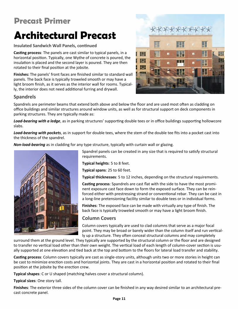
Architectural Precast Insulated Sandwich Wall Panels, continued
Casting process: The panels are cast similar to typical panels, in a horizontal position. Typically, one Wythe of concrete is poured, the insulation is placed and the second layer is poured. They are then rotated to their final position at the jobsite.
Finishes: The panels’ front faces are finished similar to standard wall panels. The back face is typically troweled smooth or may have a light broom finish, as it serves as the interior wall for rooms. Typical-ly, the interior does not need additional furring and drywall.
Spandrels
Spandrels are perimeter beams that extend both above and below the floor and are used most often as cladding on office buildings and similar structures around window units, as well as for structural support on deck components in parking structures. They are typically made as:
Load-bearing with a ledge, as in parking structures’ supporting double tees or in office buildings supporting hollowcore slabs.
Load-bearing with pockets, as in support for double tees, where the stem of the double tee fits into a pocket cast into the thickness of the spandrel.
Non-load-bearing as in cladding for any type structure, typically with curtain wall or glazing.
Spandrel panels can be created in any size that is required to satisfy structural requirements.
Typical heights: 5 to 8 feet.
Typical spans: 25 to 60 feet.
Typical thicknesses: 5 to 12 inches, depending on the structural requirements.
Casting process: Spandrels are cast flat with the side to have the most promi-nent exposure cast face down to form the exposed surface. They can be rein-forced either with prestressing strand or conventional rebar. They can be cast in a long-line pretensioning facility similar to double tees or in individual forms.
Finishes: The exposed face can be made with virtually any type of finish. The back face is typically troweled smooth or may have a light broom finish.
Column Covers
Column covers typically are used to clad columns that serve as a major focal point. They may be broad or barely wider than the column itself and run vertical-ly up a structure. They often conceal structural columns and may completely
surround them at the ground level. They typically are supported by the structural column or the floor and are designed to transfer no vertical load other than their own weight. The vertical load of each length of column-cover section is usu-ally supported at one elevation and tied back at the top and bottom to the floors for lateral load transfer and stability.
Casting process: Column covers typically are cast as single-story units, although units two or more stories in height can be cast to minimize erection costs and horizontal joints. They are cast in a horizontal position and rotated to their final position at the jobsite by the erection crew.
Typical shapes: C or U shaped (matching halves cover a structural column).
Typical sizes: One story tall.
Finishes: The exterior three sides of the column cover can be finished in any way desired similar to an architectural pre-cast concrete panel.

Page 12
Precast Primer
Architectural Precast Mullions
Mullions are thin, often decorative pieces that fill open space in a building façade. They often are isolated elements forming a long vertical line, requiring them to be cast perfectly straight to avoid any visual deformities.
Sizes and shapes can vary to satisfy both architectural and structural requirements.
Typical shapes: Square or rectangle.
Typical sizes: Up to one story tall, but longer mullions can be made.
Finishes: Three of the four sides are created with a form, as they are cast in a horizontal position. They can be finished in a variety of ways, depending on the application and the architectural purpose.
Casting process: They can be made in a long-line pretensioning facility and reinforced with prestressing strand or cast in individual forms with either prestressing strand or conventional rebar. They are cast in a horizontal position and ro-tated to their final position at the jobsite by the erection crew.

Page 13
Precast Primer
Aesthetic Versatility High Performance Precast Concrete offers inherent aes-thetic versatility due to its capabilities to be cast and fin-ished in a variety of ways. Architectural finishes can be de-signed to blend with a building’s surroundings or architec-tural context, whether those are historic or contemporary, or they can be created to make a unique statement.
These capabilities allow High Performance Precast to pro-vide the natural beauty of other types of materials while adding all of the performance benefits of precast concrete.
Panel Aesthetics
The variety of aesthetic options for architectural panels can be changed through any of these factors:
choice of aggregates
choice of matrix color
water-cement ratios
sandblasting variations
formliners
embeds
blockouts and reveals
cutouts for later attachment of veneers
finish techniques
acid etching
staining
Precasters can supply full-sized sample panels finished in accord-ance with planned production techniques. These samples ensure the desired aesthetic treatment will be achieved and can be tweaked prior to erection, giving owners and designers more con-trol over the finished appearance.
Finishes
The variety of textures that can be achieved for precast concrete components allows the naturalness of the concrete ingredients to be expressed, provides scale to the mass, expresses the plasticity of the concrete, and improves weathering characteristics. Three levels of exposure create the finished appearance:
Light exposure involves removing only the surface skin of cement and sand. This sufficiently exposes the tips of the closest coarse aggregate.
Medium exposure requires further removal of cement and sand to cause the coarse aggregates to visually appear approximately equal in area to the matrix.
Deep exposure requires cement and sand to be removed from the surface so the coarse aggregates become the major surface feature.

Page 14
Precast Primer
Aesthetic Versatility Finishes, continued
A wide range of other precast concrete sur-face finishes are available. The most common are:
Smooth or off-the-form finish.
Tooling, spalling or chipping, usually called bushhammering.
Hammered-rib or fractured-fin design.
Sand embedment.
Honing or polished finish.
Embedded Thin Brick
Virtually any clay product can be embedded into precast concrete panels, including brick (typically thin bricks), ceramic tile, and terra cotta. The products can cover the entire exposed panel surface or only a portion, serving as an accent band or con-trasting section. Embedded thin brick offers several advantages over site laid-up ma-sonry. These include:
elimination of onsite scaffolding and trades.
secure connection to the panel due to embedment in the concrete rather than framing with a thin layer of mortar.
fast erection due to brick already being installed when panels arrive at the site.
no delays for harsh weather or cold-weather procedures that slow masonry work.
single-source responsibility for panels and brick facing.
consistent quality of material and labor
Variety of mortar joint appearance options (mortar joint is actually the body of the precast concrete panel)
Handling and erection of brick- or stone-embedded panels are similar to other precast concrete wall panels, providing fast erection and quick enclosure of the building while eliminating post-erection facing needs.
Thin bricks are ¾” thick engineered masonry products, of the same composition as standard dimensional masonry. Thin bricks are engineered to tight tolerances so they fit tightly into standard forms, reducing the potential for “bleeding” around the forms during pouring.
Multiple Finishes
Design flexibility in color and texture in High Performance Pre-cast Concrete panels can be enhanced by combining multiple finishes and aesthetic treatments in one panel. This approach provides several benefits, including:
reduced number of pieces to cast.
minimized site labor.
less detailing.
fewer joints to maintain.
single-source responsibility for entire façade.

Page 15
Precast Primer
Aesthetic Versatility Formliners
Formliners are molds placed into the form to produce a decorative or designed finish on the panel face. Typically, these molds replicate the look of cut stone, brick or other textural surfaces, even wood. They often are created using the origi-nal materials to form the mold, which is then used to transfer the pattern to the front of the panel.
They also can be used to create lettering, symbols or logos in panels, as well as ribs or flutes and other geometric shapes.
Formliners can be created from a multitude of materials, including wood, steel, plaster, elastomeric, plastic or polystyrene foam. They can be reused or changed in position when designed appropriately to create a random look that simulates natural patterns.
New formliner techniques allow the transfer of photographic images to rubber forms that can be used to produce the image into the finished precast panel.
Interior Finishes The interior side of architectural precast concrete panels also can be given an aes-thetic finish, eliminating the need to provide an additional finished wall. This can save materials, time, and cost. Finish options include:
screed
light broom
float
trowel
stippled
High Performance Precast Concrete offers great versatility for using color, texture, embedded materials, formliners, and multiple colors. These capabilities give designers an almost unlimited palette from which to achieve a specific look or statement for the client that will last through the entire service life of the project.

Page 16
Precast Primer
Envelope Design Precast concrete provides an efficient, versatile and resilient envelope system. Precast walls systems, are barrier, or face-sealed systems. Unlike rainscreen systems, precast concrete does not require a cavity where moisture collects and other problems can occur. The following factors are important ele-ments of precast envelope design:
Thermal Performance
R-Value calculation
Continuous insulation
Thermal bridging
Thermal Mass
Air and Moisture Management
Air barriers and retarders (IECC 2012)
Vapor retarders and barriers
Condensation and dew point analysis
Avoidance of mold
Integration of Systems
Interfacing details
Joint details
Tolerances
Panelization
Key Precast Envelope Factors
Low permeability
3” constitutes a code-compliant vapor retarder
Sandwich wall low conductivity
Glass fiber or carbon fiber connectors reduce thermal bridging
Thermal Mass
The thermal mass of concrete reduces and delays peak loads, allows downsizing of HVAC equipment
Joints
Precast envelope systems have fewer lineal footage, and more thermally-efficient joints, than cavity wall or metal panel construction.
No Cavity
Precast sandwich wall panels consist of edge-to-edge insulation bonded between two wythes of concrete. No potential for mold growth or condensation. Precast sandwich walls typically do not require a vapor barri-er.
Low Thermal Expansion
6000 psi concrete has low expansion and contraction, so differential movement problems are almost always controlled via the panel joints.

Page 17
Precast concrete components can be joined in a variety of configurations to create an all-precast concrete structural system for a building. When combined with architectural precast concrete pan-els (or load-bearing panels, which eliminate some framing members), these pieces provide a com-plete building shell that provides single-source responsibility.
Such an approach to the building envelope can improve communication, reduce construction time, minimize site disturbance, and maximize cost efficiency. The major components typically used in such framing systems include:
Beams
Beams are horizontal components that support deck members like dou-ble tees, hollow-core and solid slabs and sometimes other beams. They typically are made in one of three shapes:
Rectangular
Inverted Tee Beams
L Beams
They can be reinforced with either prestressing strand or conventional reinforcing bars. This will depend on the spans, loading condi-tions and the produc-er’s preferred produc-tion methods.
Casting process: Prestressed beams are typically pretensioned and cast in a long-line set up similar to that used for double tees. Beams that are reinforced with conventional rebar can be cast as individual compo-nents, in shorter forms made specifically for the size of the beam. They are typically cast in the same orientation as used in the final structure.
Beams can be cast in practically any size needed to satisfy structural requirements.
Typical depths: 16 to 40 inches.
Typical widths: 12 to 24 inches.
Typical span to depth ratios: 10 to 20.
Finishes: Since beams are cast upright, the bottom, sides and ledges are cast against a form and will typically be provided with an “as cast” finish that results in a smooth, hard finish. The top is troweled by the finishing crew and can be smooth, roughened to simulate the finish of supported double tees (as in a parking structure) or intentionally roughened to create a bond with cast-in-place concrete that may be poured on top of it.
Vertical Design
Precast Vertical design provides a high perfor-mance envelope system that can also serve as a load-bearing component
A. Load-bearing wall panel (insulated with archi-tectural treatment, such as: sandblasting, re-veals, form liners, brick inlay, or other embed-ded elements
B. Double tee
C. Interior column
D. Inverted tee beam or composite
Horizontal Design A precast concrete structure is constructed with a simple array of components
A. Load-bearing architectural spandrel
B. Exterior column
C. Double tee
D. Interior column
E. Inverted tee beam or composite beam
F. Shear wall
Note: Elevator shafts and stair towers not shown in
this view.
A
B C
D
E
Precast Primer
Structural Precast

Page 18
Precast Primer
Structural Precast Columns
Columns are typically used to support beams and spandrels in applications such as parking structures and total-precast con-crete structural systems of all types. They typically are designed as multilevel components ranging from a single story to six levels or more.
Casting process: They can be made in a long-line pretensioning facility and reinforced with prestressing strand or cast in individ-ual forms with either prestressing strand or conventional rebar. They are cast in a horizontal position and rotated to their final position at the jobsite by the erection crew.
Sizes and shapes can vary to satisfy both architectural and structural requirements.
Typical shapes: Square or rectangle.
Typical sizes: From 12 by 12 inches to 24 by 48 inches.
Finishes: Since columns are cast in a horizontal position, three of the four sides are created with a form. These finishes are very smooth and most often remain “as cast” in the finished construction. The fourth side is typically troweled to match the other three sides as closely as possible.
Shear Walls
Shear walls act as vertical cantilever beams, transferring lateral forces acting parallel to the face of the wall from the superstructure to the foun-dation. Typically, there are two shear walls oriented to resist lateral loads along each principal axis of the building. They should be designed as load-bearing panels.
Typical widths: 15 to 30 feet.
Typical heights: 10 to 30 feet depending on the width and transportation limitations.
Typical thicknesses: 8 to 16 inches.
Casting process: Shear walls typically are cast flat in an individual form and reinforced with conventional rebar. They are cast in a horizontal position and rotated to their final position at the jobsite by the erection crew.
Finishes: Since shear walls are cast in a flat orientation, one side is finished in the form and the other side is manually finished. Typically, they receive the same finish and a complementary style to the surrounding structure, especially in a parking structure, where they will be visible.
Solid Slabs
Solid slabs are used as structural deck components similar to hollow-core slabs.
They can be made in a long-line pretensioning facility and reinforced with prestressing strand or cast in individual forms with either prestressing strand or conventional rebar. They are typically cast in the same position as used in the structure.
Sizes can vary to satisfy the structural requirements.
Typical width: 4 feet
Typical spans: 8 to 30 feet.
Typical thicknesses: 4 to 12 inches.

Page 19
Precast Primer
Structural Precast Lite Walls
Light or “lite” walls are shear walls used in parking structures cast with an opening in their center to provide visual continuity and to allow daylight or artificial illumination to penetrate deeper into an interior. The components provide openness and a feeling of security. These support structures should not be confused with “light wells,” which are inter-nal, open courtyards that provide daylight to the center of buildings.
As with other types of shear walls, lite walls serve as the lateral force-resisting systems in the structure. They act as cantilever beams, transferring lateral forces acting parallel to the face of the wall, from the superstructure to the foun-dation.
Casting process: They are cast in individual forms with either prestressing strand or conventional rebar. They are cast in a horizontal position and rotated to their final position at the jobsite by the erection crew.
Sizes and shapes can vary to satisfy both architectural and structural requirements.
Typical shapes: Rectangular with rectangular openings to create openness.
Typical sizes: 12 to 16 inches in width greater than the stem-to-stem spacing of the supported double tees.
Finishes: Lite walls are cast in a horizontal position, with three of the four sides created with a form. These finishes are very smooth and most often remain “as cast” in the finished construction. The fourth side is typically troweled to match the other three sides as closely as possible.
Hollowcore Slabs
Hollowcore slabs are used predominantly for floor and roof deck components for various structures including multi-family housing, hotel and condominiums, office buildings, schools and prisons.
Typical widths: 2, 4 and 8 feet; some precasters offer 10- and 12-ft widths.
Typical depths: 6, 8, 10, 12, 15 and 16 inches.
Typical span to depth ratios: Floors: 30 to 40; Roofs: 40 to 50
Casting process: Hollowcore slabs typically are cast in 300- to 500-foot-long prestressing facilities with at least one system making the slabs in 60-foot-long self-stressing forms that circulate through a production cycle. The long-line method consists of a proprietary machine specific to the brand, which extrudes the concrete and creates the voids by means of either a rotating auger or by placement of aggregate filler that is later removed.

Page 20
Precast Primer
Structural Precast
Moment Resisting Frame
Hollowcore, continued
Finishes: The form side (bottom) is smooth as cast and typically remains that way in the finished construction. It is usually an exposed-to-view surface and is often paint-ed. The top side also is usually smooth and can remain as such for direct carpet applications. It also can be kept slightly rough to receive a composite cast-in-place struc-tural topping of 2 to 3 inches or more. Topping thickness-es vary depending on application and design criteria.
Branded Processes: Each producer of hollowcore slabs uses a trademarked process that creates different shapes to form the voids within the pieces.
Double Tees
Double tees are used primarily as deck floor and roof components for any type of structure, including parking struc-tures, office buildings, and industrial buildings. They are made either:
Pretopped using a flange thickness of 4 inches, which creates the wearing surface in parking structures.
Field-topped with a 2-inch flange, on which a cast-in-place concrete composite topping of 2 to 4 inches is added in the field. For roof construction, there is typically no need to add topping on the 2-inch flange.
Double tee lengths are expanding as new techniques are be-ing employed to provide added strength and durability.
Typical widths: 8, 10, 12 and 15 feet.
Typical depths: 24, 26, 28, 30, 32 and 34 inches.
Typical span to depth ratios: Floors: 25 to 35; Roofs: 35 to 40
Double Tees can be made up to lengths of 90' - 100' —or larg-er—to create a longer clear span.
Casting process: Double tees typically are cast in 300- to 500-foot-long prestressing facilities that are sub-divided into spe-
cific length tees for a particular project.
Finishes: Form side will generally be “as cast,” resulting in a smooth, hard finish. This generally remains as is and is not painted, although it can be if desired. The top-of-flange side will be smoothed for roof construction, left rough if it will receive a field topping or broom finish (either transversally or longitudinally) or circular swirl-finished if it will be used as the wearing surface in a parking structure.

Page 21
Precast Primer
Hollowcore Precast Hollowcore planks are used predominantly for floor and roof deck
components for various structures such as residential, hotel, office
buildings, schools, and prisons. Hollowcore provides exceptional
sound transmission and impact insulation ratings, passive fire protec-
tion, and water damage resistance.
Typical widths: 2, 4, and 8 ft; 4 foot widths are most common.
Typical depths: 6, 8, 10, 12, 15, and 16 in.
Fire Ratings: 1-1/2 hr for 8” and above restrained; up to 4 hours for restrained with 3-1/8” topping
STC Ratings: 50 and above (with concrete topping)
IIC Ratings: for 8” thickness: 28 (with conc topping); 73 (with topping, carpet & pad)
Note: Each producer of hollow-core slabs uses a trademarked process that creates different shapes to form the voids within the pieces. Information on the key types of hollow-core and the signature shapes produced by each process can be found in the PCI Design Handbook 7thEdition. Load tables an span charts can be found on the PCI website via a link located under Design Resources.
Typical Hollowcore Cross-sections
Typical spans for Hollowcore are :
Plank Depth Span
6" 20 ft
8" 30 ft
10" 35 ft
12" 40 ft
16" 50 ft

Page 22
Precast Primer
Hollowcore Precast Hollowcore Specification Information
Fire Rating
• The fire rating requirement should be clearly specified in the contract documents.
Loading Conditions
• Specify all uniform loading requirements on structural plans.
• Identify line and point loads resulting from load-bearing walls, metal-stud walls, masonry walls, face brick, columns, mechanical equipment, etc.
• Identify diaphragm forces and lateral loads resulting from wind or earth pressures.
• Review roof plans for vertical protrusions such as parapets, penthouses and adjacent buildings that could require de-signing for snow drift loads.
• Plank supporting stairs require special loading con-
siderations.
• Large openings or closely spaced groups of smaller
openings will reduce the plank load carrying capacity.
Topping
• Specify whether or not concrete topping is to be
composite. Composite action requires the topping to
be bonded to the top surface of the plank. Topping
separated by a vapor barrier or insulation is noncom-
posite and must be considered a superimposed load.
• Large cambers resulting from long spans and/or
heavy loads will affect the quantity of topping, assum-
ing a level floor is required. Two inches of composite
topping at mid span is minimal, and additional thick-
ness at the ends of the plank may be required to
maintain level floor elevations.
Camber
• Camber is inherent in all prestressed products. It is
the result of the eccentric prestress force required to
resist design loads, and cannot be designed in, out, or
to an exact number. The amount of camber will de-
pend upon the span, design loads and thickness of
plank. Planks stored in the yard for more than 6
weeks, usually due to construction schedule changes,
will experience more camber growth.
• Adjacent plank of dissimilar length, strand pattern
or with openings will have inherent camber differ-
ences.
Typical Hollowcore Hanging Details
Typical Hollowcore Bearing Examples

Page 23
Precast Primer
Specialty Precast Precasters can fabricate components for a variety of specialty needs.
The high-quality manufacturing process, off-site production, and fast
erection on the jobsite provide efficiencies that make these uses a grow-
ing part of the industry. Dominant products include:
Stairs
Precast stairs are used in any application where a stair tower or individ-
ual stair units are required. These modules can provide fast erection and
durable access in buildings or parking structures.
Typical thicknesses: 6 to 10 inches.
Casting process: They are typically made as “open-Z” stair components,
in which the upper and lower landings are cast monolithically with the
tread/riser section. They also can be cast as shorter components, consisting of only the tread/riser section, which is
supported by separate landing components that span transversely to the stair section.
Stair components are typically cast either “on edge” or “upside down.” The format will depend on the size and the pro-
ducer’s preferred production method. Abrasive nosing pieces are often cast into the treads to create a non-slip surface.
Finishes: When cast on edge, the tread and bottom remain as cast and typically will remain as such in the final construc-
tion. When they are cast upside down, the bottom will be troweled to the desired degree of smoothness and typically
will remain exposed to view in the final construction.
Stadia & Arena Components
Precast concrete components can be used in a variety of ways for stadium projects, including facades, interior passage-
ways (called vomitories), and structural systems including beams and columns. Precast concrete stadium seating is a
popular option because of their fast erection without disrupting the site with falsework and added crews over long peri-
ods. Two key components comprise these seating sections:
Raker beams are angled, notched beams that support stadium riser units. They are used universally in outdoor stadi-
ums and arenas and in many indoor arenas and performing-arts theaters.
Typical sizes: Sizes can vary as required structurally
and to match varying riser sections that they support.
Typical widths: 16 to 24 inches.
Casting process: Raker beams are cast either upside
down, on their side or upright, depending on the
manufacturer’s preference. Any casting position will
result in a favorable solution. Typically, three sides
will have an “as cast” finish that results in a smooth,
hard finish. The fourth side is troweled by the finish-

Page 24
Precast Primer
Specialty Precast Stadium Risers
Stadium risers are used to support seating in stadiums, arenas, the-
aters and other types of grandstands. Typically, they are made as
single, double or triple risers with heights cast to satisfy site lines in
the venue. Specifying single, double or triple risers will depend on
the layout and may be dictated by weights and crane access during construction.
Typical spans: 8 to 50 feet.
Casting process: Risers are typically cast in self-stressing forms made for each specific project, with up to three pieces
being cast at one time, depending on the individual lengths. The bottom and vertical sections of the riser are cast
against the form and typically will remain as cast in the final construction.
Finishes: The top (wearing surface) is typically troweled to the desired degree of smoothness or made slightly rough-
ened to create a non-slip surface.
Modular Units
Precasters can produce modular precast concrete units
that include a roof, floor, front and back walls plus two
side walls if desired. The modules’ key benefit, in addition
to the speed with which these “building blocks” can be
erected on site, comes from the precaster being able to
outfit and finish the modules at the plant so they arrive at
the site nearly complete.
These modules are used for a variety of applications where
relatively small, repetitive rooms are needed on a rapid
schedule. Typical uses include:
prison cells
classrooms
hotel and motel rooms
The modules can be single- or multi-level structures as high as 10 to 12 stories. In prison applications, the modules are
cast as single- or multi-cell units with as many as four cells in one monolithic component. The configuration typically
includes the inmate cell and a vertical “chase” between cells for mechanical, electrical and plumbing accommodations.
Typically, the interior exposed walls are epoxy painted, and the module is outfitted with as much of the MEP accommo-
dations as possible in the producer’s plant. Final fit up is done at the jobsite. Exterior walls can be made with insulation
similar to a sandwich wall panel and can receive virtually any kind of architectural treatment.
Casting process: Specialized, often proprietary, steel formwork is used, with mechanisms that adjust and “strip” the
module from the form. These often are proprietary to the manufacturer. The special forms allow all wall surfaces to be
cast against a form. When stripped from the form, the floor or roof surface is troweled to the desired degree of
smoothness, and the wall surfaces are typically prepped to fill bug holes before painting.
Finishes: Typically, the interior walls of the inmate cells are sandblasted, any bug holes are filled and they are epoxy-
painted before installation of items mentioned above.

Page 25
Precast Primer
Joint Design Precast concrete systems require careful attention to joint design, for both
aesthetic and maintenance purposes. Exterior precast joints typically con-
sist of an exterior sealant and backer-rod joint combined with a similar
interior joint. The exterior joint is subject to weather and temperature
fluctuations, and should be formed with high performance sealant and
inspected every few years for deterioration.
Floor joints can pose particular design constraints, as they must often be
flush with the precast product for finish purposes. In hollowcore design,
the plank joint must be grout-
ed to provide a composite
structural system.
Key Joint Design Considerations
Fire Protection: Where the precast wall is part of a fire-resistant barri-
er, use ceramic fire felt of the required thickness to obtain the desired fire
rating.
Continuous Insulation: To maintain continuous insulation at the exte-
rior envelope, utilize rigid insulation or mineral wool between the sealant
barriers .
Interior Protection: Where the interior wythe of a precast sandwich
panel is also utilized as the interior finish, consider installing tamper-proof
sealant or a finished tee insert to protect the interior sealant joint from
damage.
N.A. = Not applicable
*Panel equivalent thicknesses are for carbonate concrete. For siliceous aggregate concrete, change “4, 5, 6, and 7” to “4.3, 5.3, 6.5, and 7.5”. For sand-lightweight concrete, change “4, 5, 6, and 7” to “3.3, 4.1, 4.9, and 5.7” respectively.
The tabulated values apply to one-stage joints and are consecutive for two-stage joints. Interpolation may be used for joint widths between 3/8” and 1”.

Page 26
Precast Primer
Construction Speed Speed to Occupancy
Many of precast concrete’s attributes and technologies ensure the design and construc-
tion process move quickly and smoothly. These come into play at each stage of the pro-
cess:
Design
The repetitive nature of precast concrete panels and components allow design work to move more quickly to the shop
-drawing stage. Precast components also can aid a fast-track design by completing drawings while other design work is
still underway.
Fabrication
Precast concrete components can begin casting as soon as drawings are completed and while site preparation and
construction of foundations begins. Casting and storing components ensures they are ready for delivery as soon as the
site is ready.
Scheduling
Because precast concrete components are fabricated under factory-controlled conditions at the plant, harsh winter
weather does not impact the product schedule or product quality. This eliminates the need for cushions in the timeta-
ble to accommodate unforeseen delays due to weather. Thus, interior trades can begin work earlier, which can be
critical as winter approaches.
Construction
Erecting precast concrete components can be achieved quickly, using just-in-time delivery or pulling them from a near-
by staging area in the sequence best designed to complete erection quickly. Factory production also provides tight tol-
erances, minimizing field adjustments.
Interior Completion
Precast concrete insulated sandwich
wall panels provide a finished interior
wall that avoids the time and cost of
furring and dry-walling while offering
energy efficiencies. The entire wall
assembly can be constructed with one
trade compared to up to seven for a
typical wall assembly. Using hollow-
core planks to create combined ceiling
and flooring units speeds construction
more.
0 20 40
Cast-in-Place
Steel/Brick & Block
Steel &Precast
Precast
On-site Construction Time-Weeks
Sitework &FoundationSuper StructureSteel,
Brick & CMU
Cast-in-Place

Page 27
Precast Primer
Design Economy A variety of cost calculations are required to determine what design ap-proaches will most effectively achieve the owners’ goals. Initial in-ground costs are the most obvious expenses, but hidden and longer-term costs are also significant and can be greatly impacted by design decisions.
Projects should be considered holistically, understanding that each system and decision impacts others. All products and systems should be designed to work together to enhance each other without creating redundancy or ineffi-ciencies.
The three key types of costs are:
In-Ground Cost
Initial or in-ground costs are typically the driving force when determining budgets and where to allocate funds. Precast
concrete components provide a variety of savings in ways that are not always considered. These savings include:
A. Speed of design and construction, which can be saved
through:
the design process, because precast requires less façade detailing and engineering details are provided by the precast-er.
the fabrication process, which can progress while per-mitting and foundation work are underway. As a single-source supplier for a large portion of the structural system, precasters help maintain the critical-path scheduling.
the erection process, during which precast concrete com-ponents are set and connected rapidly, cutting weeks or months from the schedule. This speed allows construction to get into the dry quicker, giving interior trades access more rapidly.
the finishing process, especially with precast concrete insulated sandwich wall panels, which create a finished interior wall that eliminates the time and cost of drywalling. Architectural panels can have a variety of colors and textures, eliminating the need to field-set trim pieces or paint the facade.
B. Design economy, which can be achieved with architectural precast concrete panels through:
Selecting economical aggregates and textures.
Using repetitive units and effective production and erection details.
Limiting the number of pieces (rather than the size of each).
C. Material Efficiency, which can be achieved by using precast concrete components for several functions, such as:
using hollowcore planking and double tees as combined ceiling/flooring units
using spandrel panels in parking structures as vehicle-impact restraints.
using load-bearing precast concrete walls and hollowcore planks or double tees to create the framing and cladding system together.
using embedded thin brick or formliners to create a brick-like appearance, eliminating labor costs.
using textures and finishes to replicate stone materials, eliminating the need to transport heavy masonry or to apply stone veneers.

Page 28
Precast Primer
Design Economy D. Construction Efficiency, gained through precast concrete’s factory-controlled conditions, which can:
ensure harsh winter weather does not impact the production schedule or product quality.
allow components to be erected through the winter months, cut overhead costs, and provide quicker occu-pancy.
maintain planned construction schedules with less need for “cushions” that make later scheduling more diffi-cult.
create tight tolerances that facilitate erection and minimize field adjustments.
limit façade construction requirements to one trade, even for using or replicating brick, stone veneers or other aesthetic needs, eliminating the need for scheduling and budgeting additional subcontractors.
Effect of Repetition on Panel Square-Foot Cost
Number Panel size Mold Cost Cost per square foot of reuses (square feet)
____________________________________________________________________________
1 200 $3,000 $15.00
10 200 $3,000 $1.50
20 200 $3,000 $0.75
30 200 $3,000 $0.50
Source: DN-11-02: Designer’s Notebook: Design Economy.
Note: This table reflects a typical cladding application of precast concrete architectural panels.
The same or similar process can be used for a total-precast concrete structure.
Effect of Panel Size on Erection Cost per Square Foot (based on a minimum erection time of one month)
Panel size (SF) Erection Cost per Piece, $/square foot
$500 $800 $1200 $1,800
50 10.00 16.00 24.00 36.00
100 5.00 8.00 12.00 18.00
150 3.33 5.33 8.00 12.00
200 2.50 4.00 6.00 9.00
250 2.00 3.20 4.80 7.20
300 1.66 2.66 4.00 6.00
Source: DN-11-02: Designer’s Notebook: Design Economy.
Note: Hypothetical erection costs only. Erection costs vary by project size and complexity
Precast Budget Keys
Economy of scale
Use of thin-brick judi-ciously
Flexibility in achieving aesthetic effects
Take advantage of schedule benefits
Involve precaster early in design

Page 29
Precast Primer
Precast Resiliency High Performance Precast Concrete’s resiliency expands on durability to include the ability to help restore the building to its full functional capacity with minimal efforts and resources after a major event such as an earthquake or hurricane. This also helps minimize negative effects to the environment after such an event, since resilient structures do not need to be completely rebuilt
Protection from Natural Forces
Precast concrete designs can offer protection against such natural disasters as storms and floods, earthquakes, hurri-canes, tornados and other high-wind situation. Considering these benefits early in the design process maximizes pre-cast concrete’s effectiveness against each of these issues.
Storm resistance
A variety of precast concrete components can be used to create hurricane- and tornado-resistant structures, including foundation walls, load- or non-load-bearing precast concrete wall panels, and hollowcore plank for roofing and floor-ing.
Precast concrete also offers protection from wind-borne debris. Impact studies highlight this capability. During recent tests, lengths of 2x4 projectiles were fired at 100 mph toward various wall systems. The projectile penetrated the 2 x 4 stud and cavity wall systems with 3/4” OSB sheeting: one finished with vinyl siding, and the other with a 4” brick ve-neer. But the 2 x 4 projectile splintered when it impacted the precast concrete sandwich wall system.
With its high durability, precast concrete construction also resists surge damage. The use of precast concrete pilings can reduce the damage from water surging beneath a slab on grade.
Earthquake Resistance
Precast concrete can be designed to resist severe seismic events. New connection approaches, which have been ap-proved or are in the process of being evaluated by code authorities, provide lateral resistance that meets building codes in earthquake-prone areas.
Precast components can span long distances between attachments to the main structure, even in seismic areas. Sever-al of these concepts have been adopted into building codes such as ACI -318 which is referenced by the International Building Code. They include:
a hybrid post-tensioned precast frame, codified in 1999, that withstands high lateral forces and allows a building to “self-right” itself after a seismic event.
a shear-wall system, adopted for the 2003 edition of the National Earthquake Hazard Reduction Program Provi-sions).
a pre-tensioned precast frame, Continuous, partially bonded pre-tensioned beams are connected to column seg-ments. A moment connection is established between the beam and column through joint sleeves.
These options allow designers to meet any seismic challenge in any type of building nationwide. They can ensure that buildings not only remain safe during an earthquake but right its structure afterward, providing a safe haven and ena-

Page 30
Precast Primer
Precast Resiliency Resistance from Manmade Forces
Designers also need to protect against man-made forces, such as those caused by sprinkler activations, explosions, or fires. Planning and designing for these with High Performance Precast Concrete can ensure buildings are prepared for any situation.
Blast Resistance
Precast concrete components can aid designers in meeting protective Anti-Terrorist/Force Protection design require-ments for government and high-profile buildings. This can be achieved in three ways:
architectural precast concrete can be designed with sufficient durability to mitigate the effects of a bomb blast and satisfy General Services Administration and Department of Defense requirements.
structural precast concrete can be designed with the proper connections and the necessary protection against pro-gressive collapse.
protective barriers in decorative finishes can be used at the building’s perimeter to limit and control vehicle access without disrupting neighborhood aesthetics.
Test results show that minimum required stand-off distances can be reduced when using precast concrete compared to traditional design requirements due to its inherent strength and resiliency.
Fire Resistance
Precast concrete does not combust, providing passive fire protection. Benefits accruing from this include:
easily achieving fire ratings required by building codes with no additional post-construction treatments.
providing an inherent passive fire-protection system that enhances other fire systems, such as sprinklers, which can fail.
slowing the spread of fire, giving occupants more time to evacuate the premises and fire fighters more time to control the blaze.
protecting walls and roofing elements during wildfires.
allowing reuse of wall panels when the building is retrofitted.
withstanding structural failure longer than other materials.
closing of joints during fire exposure due to expansion when heated.
Better Indoor Environmental Quality
High Performance Precast Concrete enhances indoor air quality due to a variety of factors:
Its inorganic composition does not provide food for mold spores, minimizing its ability grow.
Its fast erection encloses buildings faster, providing a barrier between outside contaminants and moisture.
Its capability to leave interior faces exposed, eliminating the need for drywall that can encourage mold growth.
Page 31
Precast Primer
Risk Management Precast concrete construction reduces professional liability for design professionals over cav-ity wall construction and other envelope systems that do not heavily involve the manufac-turer in the detailing of the system and require a number of different products and subcon-tractors to construct.
Key Precast Risk Reduction Factors
Tier One Subcontractor
When utilized for both structure and envelope, precast systems comprise a high percentage of the total project scope. A contractor with a large percentage of work is considered a Tier One sub. Tier One subs reduce the coordination and communication burden for the archi-tect.
Minimizing Number of Trades
Precast architectural wall panels can incorporate a variety of façade design elements, as well as continuous rigid insula-tion, without the detailing and coordination risk inherent in built-up facades utilizing a variety of products and requiring numerous subcontractors. The result is fewer RFIs and reduced change order risk for design professionals.
Design Assist Role
Precast producers offer design assistance service, and the industry recommends that architects contact them early in schematic design to allow them to assist in budget and schedule management. Precasters also provide specialized engi-neering and detailing assistance not offered by many structural engineers.
Reduced Coordination Issues
Fewer subs and integrated finishes in a single product result in a much lower coordination burden for the design profes-sional—and reduced professional liability as well.
Production Standards
PCI Certification means a consistent standard of quality, backed by a national technical institute and inspection program that architects can rely on in specifying precast.
Schedule Conformance
Precast is the fastest building system available. Precast construction can save up to 40% in schedule time (and corre-sponding general conditions costs) over cast-in-place, masonry, and steel construction.
Budget Conformance
Early interaction with a precaster provides the architect with reliable cost and schedule estimates and assistance in producing the most economical design
Minimizing Winter Costs
Precast erection is largely unaffected by cold temperatures or snow/ice, and does not require winter conditions procedures or change orders.
Performance Liability
Precast high performance wall panels provide scalable performance through adjustable continuous insulation with no thermal breaks, and the benefits of thermal mass in reducing peak loads and HVAC requirements.
Precast Multi-component Facades
Cavity wall appearance with less risk
–Typically 12’ wide x 30-40’ high
–6000 psi concrete
–Can be load-bearing or non-load bearing
–Multiple colors and textures can be achieved in single panels
–High performance sandwich panels fea-ture continuous insulation between two wythes of concrete

Page 32
Precast Primer
Precast Innovations As a fabricated material produced under closely controlled factory conditions, precast concrete provides the capability to adapt its composition and design to new techniques that arise. As a result, architects, engineers and precasters continue to push the bounda-ries of the material’s applications and design parameters.
New concepts in precast concrete continue to be introduced in an effort to continually improve the material to produce better looking, more economical and more efficient designs. Some of the current advances include:
Self-Consolidating Concrete (SCC)
SCC, also called self-consolidating concrete, features a concrete mixture that incorporates high-range water-reducing admixtures that significantly increase the material’s workability and fluidity. As a result, it flows quickly into place, fills every corner of a form and surrounds even densely packed reinforcement. Among its benefits are quality, aesthetic values, speed, design flexibility, and durability. SCC is most often used in long-line casting such as for double-tees, as well as pieces with dense reinforcing.
Ultra-High-Performance Concrete (UHPC)
UHPC consists of a steel fiber-reinforced, reactive-powder concrete that provides a compressive strength of 30,000 psi, more than twice that of any high-performance concrete used to date. It also includes steel or organic fibers measuring 1/2-inch long and six mills in diameter, which add tensile strength and toughness.
Carbon-Reinforced Precast Concrete
Produced under the name CarbonCast by Altus Group, a nationwide consortium of precast concrete companies, uses conventional steel for primary reinforcing and a resin-bonded, carbon-fiber grid for secondary reinforcing and shear transfer. The carbon-based product eliminates the potential for corrosion caused by secondary reinforcing. This in turn eliminates the excess concrete cover normally needed to protect steel from corrosion that results from exposure to moisture. CarbonCast is a proprietary product not available through all precasters.
Molded Concrete
Molded Concrete, in which ultra-high performance, fiber-reinforced concrete (UHPFRC) is molded into shapes to achieve specific attributes for projects. This concrete offers high compressive strength, (more than 22,000 psi) and flexural strength. The low weight and thinness allows the material to be cast for a wider range of applications. A high-quality finish can be achieved in a durable, quickly erected component.
Self-Cleaning Concrete
Proprietary technology (based on particles of titanium dioxide) is what makes this cement special. The technology can be applied to white or gray cement and it works like any other Portland cement. It is capable of breaking down smog or other pollution that has attached itself to the concrete substrate, in a process known as photocatalysis. As sunlight hits the surface, most organic and some inorganic pollutants are neutralized. They would otherwise lead to discolored concrete surfaces.
The titanium-based catalyst is not spent as it breaks down pollution, but continues to work. Typical products are oxygen, water, carbon dioxide, nitrate, and sulfate. Because rain washes away the pollution from the concrete sur-face, buildings stay cleaner and do not require chemical applications that are potentially harmful to the environ-ment. Note: Titanium dioxide has recently been classified by the International Agency for Research on Cancer (IARC) as a Group 2B hazard, possibly carcinogenic to humans. The potential risks of this product are under study by the concrete industry.

Page 33
Precast Primer
Specifying Precast Concrete
To ensure accredited certification is used on each project, the Precast/Prestressed Concrete Institute (PCI)
recommends that specifying architects reference the following:
Manufacturer Qualifications: The specifying process should begin with a list of the required precast concrete prod-
ucts, from which the appropriate product group and category for each product can be determined based on the
product’s use, the method of reinforcement and special surface finishes. PCI recommends manufacturer qualifications
according to the following specification:
“The precast concrete manufacturing plant shall be certified under the PCI Certified Plant Program. The manufac-
turer shall be certified at the time of bidding. Certification shall be in the following product group(s) and category
(ies):
Choose one or more of the following, as applicable:
GROUP A – ARCHITECTURAL PRODUCTS
AT – Architectural Trim Units
A1 – Architectural Precast Products
GROUP B OR BA – BRIDGE PRODUCTS
B1 or B1A – Precast Bridge Products (No Prestressed Reinforcement)
B2 or B2A – Prestressed Miscellaneous Bridge Products (Non-superstructure)
B3 or B3A – Prestressed Straight-Strand Bridge Beams (Superstructure)
B4 or B4A – Prestressed Deflected-Strand Bridge Beams (Superstructure)
[Group BA products require an architectural finish.]
GROUP C OR CA – COMMERCIAL (STRUCTURAL) PRODUCTS
C1 or C1A – Precast Concrete Products (No
Prestressed Reinforcement)
C2 or C2A – Prestressed Hollow-Core and
Repetitive Products
C3 or C3A – Prestressed Straight-Strand
Structural Members
C4 or C4A – Prestressed Deflected-Strand
Structural Members
[Group CA products require an architectural fin-
ish.]

Page 34
Precast Primer
Specifying Precast Concrete
Specification Guidance
Describe the type and quality of the materials incorporated into the units, the design strength of the concrete, the mix and finishes and the tolerances for fab-rication and erection. In the event of a performance specification appropriate data should be included for the precaster to assess the scope and quality of the precast units to be fabricated.
Specifiers should consider permitting variations in production, structural design, materials, connection and erection techniques to accommodate varying plant practices. Specifying the results desired without specifically defining manufac-turing procedures will ensure the best competitive bidding. Required submittals should also include range-bracketing samples for color and texture.
The specification section should include connection components embedded in the precast concrete, related loose connection hardware, and any special devic-es for lifting or erection, if required, as responsibilities of the precaster. Items to be specified in other sections include building frame support provisions re-quired to support units, including portions of connectors attached to the struc-ture, joint sealing and final cleaning and protection.
General Categories of Precast Specifications
CATEGORY S1: Simple Structural Systems
This includes horizontal decking members (such as hollowcore slabs on masonry walls), and single-lift wall panels attached to a structure.
CATEGORY S2: Complex Structural Systems
This includes everything contained in S1 as well as total–precast concrete construction, multi-product structures (those that combine vertical and horizontal members), and single- or multistory load-bearing members, including those with architectural finishes.
CATEGORY A: Architectural Systems
This includes non-load-bearing cladding and GFRC products, which may be attached to a supporting structure.
PCI recommends manufacturer qualifications according to the following specification:
“Erector Qualification: Prior to beginning any work at the jobsite, the erecting organization, including all crews
erecting precast concrete, shall be certified in category[ies] [A, S1, and/or S2] under the Precast/Prestressed Con-
crete Institute (PCI) Erector Certification Program.”
For a complete guide specification for structural or architectural precast concrete, contact MAPA at
[email protected] or 800 453 4447

Page 35
Precast Primer
PCI Certification Since 1967, PCI’s Plant Certification Program has ensured that each plant operated by a
member has developed and documented an in-depth, in-house quality system based on
time-tested national industry standards. PCI Certification is included in MasterSpec™, as
well as a number of federal and military specifications.
Each plant undergoes two thorough, unannounced audits each year. The audits are conducted by independent ac-
credited engineers, who inspect the company according to the types of products being manufactured.
PCI also certifies each plant’s quality-control personnel, through its Plant Quality Personnel Certification Program,
which began in 1985. And it certifies erection procedures and field-quality control through its Field Qualification Pro-
gram and Certified Erector Program.
A variety of benefits accrue to architects by using products fabricated at PCI-Certified plants. These include:
Cost
Certification does not increase the cost of using manufactured components. Most of the cost typically associated
with subscribing to a certification program represents the cost of doing the job right.
Common Standards
Specifying products from certified fabricators ensures that a uniform yardstick of per-
formance is being equally applied to all bidders. This reduces the temptation to cut
corners, often in ways that are not readily apparent but can be significant to the fin-
ished project.
Reliable Project Partner Certified fabricators make significant investments in plants, procedures, and people
to meet certification standards. They develop a habit of measuring and achieving
quality, and they offer a documented history of consistent production to meet specifi-
cations.
Faster Erection
Using quality products leads to more efficient field operations, which in turn prevents schedule delays. Quality con-
trol systems ensure components are properly identified and delivered in the appropriate number and order. It also
ensures tight tolerances so they fit together quickly, cutting on-site labor and scheduling.
As-Designed Becomes As-Built
A designer’s vision, and his reputation for quality, depends on the capabilities of the fabricator and installer. Certifi-
cation ensures the finished project meets the designer’s expectations and requires less supervision and field inspec-
tion, saving time and money.

Page 36
Precast Primer
Resources
Online Resources
Precast/Prestressed Concrete Institute (PCI): www.pci.org
Mid-Atlantic Precast Association (MAPA):
www.mapaprecast.org
Concrete Joint Sustainability Initiative (CJSI): www.sustainableconcrete.org
Portland Cement Association (PCA): www.cement.org
American Concrete Institute (ACI): www.concrete.org
Architectural Design Resources
Precast Primer: (available from MAPA)
Architectural Precast Concrete manual (3rd edition): (available from MAPA in
PDF version)
Designer’s Notebooks: http://www.pci.org/Design_Resources/
Guides_and_Manuals/Designer_s_Notebooks/
CAD Details: www.mapaprecast.org
Specifications: (available from MAPA)
PCI Color & Texture Manual (available from PCI in print version or from MAPA
in PDF version)
Engineering Resources
PCI Design Manual (7th edition): (https://www.pci.org/bookstore/storefront.aspx
PCI Design Manual (6th edition): (available from MAPA in PDF version)
Hollowcore Design Manual (2nd edition): (available from MAPA in PDF version)
Contact MAPA:
800 453 4447