highly automated vehicles for intelligent transport … · highly automated vehicles for...
TRANSCRIPT
HAVEit 19.06.2009
Highly automated vehicles for intelligent transport
7th Framework programme ICT-2007.6.1
ICT for intelligent vehicles and mobility services Grant agreement no.: 212154
The future of driving.
Deliverable D12.1 Architecture
Version number Version 1.0Dissemination level PULead contractor Continental Automotive GmbHDue date 31.01.2009Date of preparation 03.02.2009
HAVEit 19.06.2009
Deliverable D12.1 Version 1.0 ii Architecture
Authors
Erika Jakobsson, Volvo Technology Corporation Achim Beutner, Volvo Technology Corporation Stefan Pettersson, Volvo Technology Corporation Arne Bartels, Volkswagen Fredrik Seglö, Haldex Anders Lindqvist, Haldex Anders Nilsson, Haldex Hannes Stratil, Efkon AG Florian Ahlers, Ibeo Kay Fuerstenberg, Ibeo Angelos Amditis, ICCS George Thomaidis, ICCS Katia Pagle, ICCS Frank Flemisch, DLR Gerald Temme, DLR Henning Mosebach, DLR Anna Schieben, DLR Jan Schomerus, DLR Estelle Frey, Knowllence Marc Sabatier, Knowllence Nadja Rauch, WIVW Philipp Luithardt, USTUTT Michael Armbruster, USTUTT Arnaud de La Fortelle, INRIA Fawzi Nashashibi, INRIA Lydie Nouveliere, LCPC Said Mammar, LCPC Sebastian Glaser, LCPC Alain Dufaux, EPFL Davide Manetti, EPFL Philippe Allemann, EXP Serge Boverie, Conti Automotive Alain Giralt, Conti Automotive Matthias Strauss, Continental Teves Waldemar Schrinner, Continental Teves Andreas Abele, Conti Automotive Holger Zeng, Conti Automotive Michaela Fiedler, Conti Automotive Alfred Hoess, Conti Automotive

HAVEit 19.06.2009
Deliverable D12.1 Version 1.0 iii Architecture
Project Managers
Alfred Hoess
Continental Automotive GmbH
Siemensstrasse 12
93055 Regensburg, Germany
Phone +49 941 790-5786
Telefax +49 941 790 99 5786
E-mail: [email protected]
Holger Zeng
Continental Automotive GmbH
Siemensstrasse 12
93055 Regensburg, Germany
Phone +49 941 790 92330
Fax. +49 941 790 99 92330
E-mail: [email protected]
Project Co-ordinator
Reiner Hoeger
Continental Automotive GmbH
Siemensstrasse 12
93055 Regensburg, Germany
Phone +49 941 790 3673
Fax +49 941 790 99 3673
E-mail [email protected]
Copyright: HAVEit Consortium 2008
HAVEit 19.06.2009
Deliverable D12.1 Version 1.0 iv Architecture
Revision and history chart
Version Date Reason
0.1 2008-11-28 Initial template with table of contents proposal by Alfred Hoess.
0.2 2008-12-18 CTA, VTEC, DLR and CAG input included.
0.3 2008-12-30 CAG interactor list included.
0.3 2009-01-03 EXP input included.
0.3 2009-01-06 USTUTT and VW input included.
0.3 2009-01-07 WP4300 FBD updated. Section "Interactor description" added. Subsec-tions for the segments of the interactor table added.
0.4 2009-01-09 FBDs for all demonstrators updated to the latest state in the TDC data base.
0.5 2009-01-11 KN and HLX inputs included, remaining sections added, interactor definition updated, formatting and final reading.
0.6 2009-01-12 Spell checked
0.7 2009-01-29 New FBD pictures, CTA, WIVW, DLR input included, reviewer A comments worked in.
0.8 2009-01-30 Comments of reviewer B included
0.8 2009-02-01 Comments of reviewer C included
1.0 2009-02-03 Methodology explanation updated; FBDs updated; final comments by PM; final editing and formatting; delivery to EC.
2009-06-19 Final EC and reviewer comments included. Generation of public deliverable version.
HAVEit 19.06.2009
Deliverable D12.1 Version 1.0 v Architecture
Table of contents
Revision and history chart.............................................................................................................. iv Table of contents............................................................................................................................. v Figures ........................................................................................................................................vi Tables .......................................................................................................................................vii Executive summary ......................................................................................................................viii 1 Introduction ..................................................................................................................... 1 2 Functional block diagram................................................................................................ 4
2.1 From SADT to FBD ........................................................................................ 6 2.2 HAVEit generic architecture......................................................................... 11 2.2.1 Generic FBD................................................................................................. 12 2.2.2 Characterization of contact functions .......................................................... 14 2.3 Vehicle specific adaptations......................................................................... 17 2.3.1 Automated roadwork assistance FBD ......................................................... 17 2.3.2 Automated queue assistance FBD .............................................................. 24 2.3.3 Temporary auto-pilot FBD............................................................................ 28 2.3.4 Active green driving FBD ............................................................................. 35
3 Interactor definition ....................................................................................................... 39 4 Further architecture investigations ............................................................................... 40 5 X-by-Wire: Architectural considerations ....................................................................... 41
5.1 Steer- and Brake-by-wire architecture ......................................................... 42 5.1.1 Steer-by-wire architecture ............................................................................ 42 5.1.2 Brake-by-wire architecture ........................................................................... 45 5.2 Safety considerations - 2E architecture ....................................................... 47 5.2.1 Safety ........................................................................................................... 48 5.2.2 Redundancy management........................................................................... 49 5.3 FlexRay communication............................................................................... 51
6 Conclusions .................................................................................................................. 55 References .................................................................................................................................... 56 Annex 1 Abbreviations ................................................................................................................ 57 Annex 2 Glossary ........................................................................................................................ 58
HAVEit 19.06.2009
Deliverable D12.1 Version 1.0 vi Architecture
Figures
Figure 1: Different steps of the requirements and specification phase ........................................ 1 Figure 2: Rules of the SADT method ........................................................................................... 4 Figure 3: Top-down vision of the SADT method .......................................................................... 4 Figure 4: Definition of physical links is not supported by the SADT method ................................ 5 Figure 5: Example for an FBD...................................................................................................... 5 Figure 6: Conversion of external interactors from SADT to the FBD ........................................... 7 Figure 7: Conversion of (logical) components from SADT to the FBD......................................... 8 Figure 8: Transfer of internal interactors from SADT into FBD .................................................... 9 Figure 9: Example of the result of a conversion of SADT into FBD (perception layer) .............. 10 Figure 10: HAVEit block diagram ............................................................................................... 11 Figure 11: HAVEit generic functional block diagram (basis WP4300) ....................................... 13 Figure 12: Proposed WP4300 network topology........................................................................ 16 Figure 13: HAVEit WP5100 functional block diagram ................................................................ 19 Figure 14: Assignment of logical components to physical processing units and interactors
concerned in WP5100............................................................................................... 23 Figure 15: HAVEit WP5200 functional block diagram ................................................................ 25 Figure 16: Assignment of logical components to physical processing units and interactors
concerned in WP5200............................................................................................... 27 Figure 17: HAVEit WP5300 functional block diagram ................................................................ 29 Figure 18: Assignment of logical components to physical processing units and interactors
concerned in WP5300............................................................................................... 34 Figure 19: HAVEit WP5400 functional block diagram ................................................................ 36 Figure 20: Assignment of logical components to physical processing units and interactors
concerned in WP5400............................................................................................... 38 Figure 21: Configuration of the HAVEit steer-by-wire system .................................................... 43 Figure 22: Architecture of the steer-by-wire system................................................................... 44 Figure 23: Energy block diagram for the steer-by-wire system .................................................. 45 Figure 24: Brake-by-wire communication network architecture ................................................. 46 Figure 25: Principal power supply architecture for WP4200 ...................................................... 47 Figure 26: Overview of the software-layers of the USTUTT redundancy management............. 49 Figure 27: HAVEit development process for 2E systems........................................................... 51 Figure 28: Gateway hardware architecture ................................................................................ 52 Figure 29: Gateway software architecture.................................................................................. 53
HAVEit 19.06.2009
Deliverable D12.1 Version 1.0 vii Architecture
Tables
Table 1: Assignment of interactors to contact functions (Icf, Ecf) and clustering of contact functions to bus links (group name) for the HAVEit generic FBD (WP4300)................ 16
Table 2: Assignment of interactors to contact functions (Icf, Ecf) and clustering of contact functions to bus links (group name) for the WP5100 demonstrator ............................. 22
Table 3: Interactors to be transferred between the different WP5100 physical processing units23 Table 4: Assignment of interactors to contact functions (Icf, Ecf) and clustering of contact
functions to bus links (group name) for the WP5200 demonstrator ............................. 26 Table 5: Required bus connections and interactors to be transferred (WP5200) ...................... 27 Table 6: Assignment of interactors to contact functions (icf, ecf) and clustering of contact
functions to bus links (group name) for WP5300 demonstrator ................................... 33 Table 7: Required bus connections and interactors to be transferred (WP5300) ...................... 34 Table 8: Assignment of interactors to contact functions (Icf, Ecf) and clustering of contact
functions to bus links (group name) for the WP5400 demonstrator ............................. 37 Table 9: Required bus connections and interactors to be transferred (WP5400) ...................... 38
HAVEit 19.06.2009
Deliverable D12.1 Version 1.0 viii Architecture
Executive summary
The deliverable D12.1 represents the second out of three HAVEit deliverables covering the results of the requirements and specification phase:
• D11.1 has been dedicated to the definition of HAVEit's highly automated vehicle appli-cations and their requirements. The public deliverable has been delivered on September 30, 2008.
• D11.2 is describing the key specifications for all components used in the seven HAVEit demonstrators.
• D12.1 covers the HAVEit architecture and describes the data to be exchanged between the different components and function blocks in detail.
The structure of D12.1 follows the procedure the consortium applied to arrive at a common HAVEit architecture and required demonstrator specific extensions. The function oriented SADT (structured analysis design tool) view on the HAVEit systems, which has been described in detail in D11.1, has been transferred into a more hardware oriented FBD (functional block diagram). The procedure and resulting physical contacts between the hardware entities are de-scribed in chapter 2. Having defined the physical contact functions, it is known which informa-tion needs to be transferred via the physical contact functions. The information is included in the so-called interactors. This means that the precise interactor description is the key element for every future data exchange between the different function blocks, the different hardware entities and thus for the different partners collaborating in the realization of the demonstrators.
Therefore, a lot of effort has been spent on defining the content of each interactor as precise as possible down to the level that allows the calculation of the required data rate. As a result, a detailed table with more than 10000 lines is available which describes the interactor content. Chapter 3 of this document summarizes the purpose of interactors.
Chapter 4 gives an outlook on additional architecture considerations that will be executed within SP2000 and WP4300, e.g. bus load estimation, tool based FMEA1, FTA2 and so on. A link with the FP7 project ATESST2 (see www.atesst.org) has been established: ATESST2 will use the common HAVEit architecture as an application example. Chapter 5 presents the special architecture considerations for brake-by-wire and steer-by-wire systems.
It is important to note that despite some varying components in the different demonstrators, the communication between the components will be the same for all vehicles. This common understanding - an important specification goal - has been achieved by open and intensive communication between all partners of the HAVEit consortium.
The overall conclusions from the results achieved during the requirements and specification phase of HAVEit (see requirements deliverable D11.1, specification deliverable D11.2 and ar-chitecture deliverable D12.1) are:
• Function requirements have been derived and can be fulfilled (see D11.1).
• Component specifications have been derived and can be fulfilled (see D11.2).
• A common HAVEit architecture suiting both the requirements of functions and compo-nents and the requirements in terms of safety have been derived and agreed on (D12.1). The information flow has been defined in detail and a process has been established to maintain and track future adaptations using the TDC tools to ensure a consistent data base throughout the remaining project phases.
1 FMEA: Failure Mode and Effects Analysis 2 FTA: Fault Tree Analysis
HAVEit 19.06.2009
Deliverable D12.1 Version 1.0 1
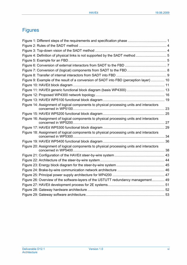
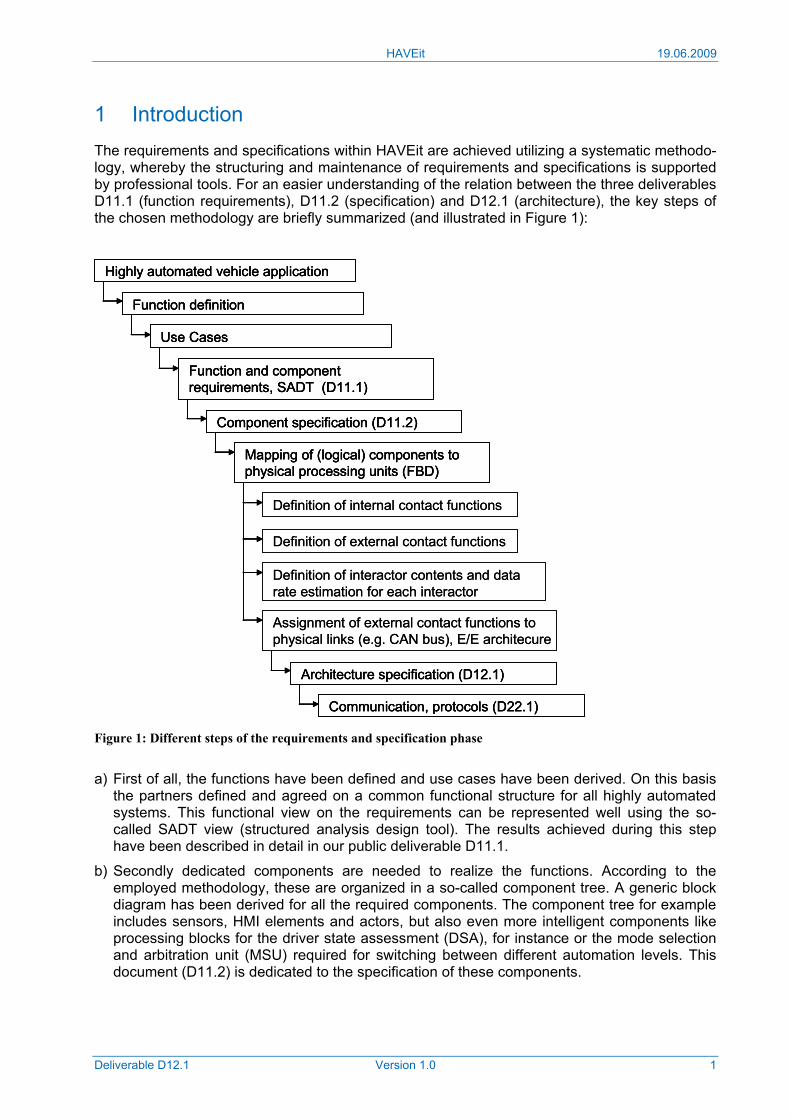
1 Introduction The requirements and specifications within HAVEit are achieved utilizing a systematic methodo-logy, whereby the structuring and maintenance of requirements and specifications is supported by professional tools. For an easier understanding of the relation between the three deliverables D11.1 (function requirements), D11.2 (specification) and D12.1 (architecture), the key steps of the chosen methodology are briefly summarized (and illustrated in Figure 1):
Figure 1: Different steps of the requirements and specification phase
a) First of all, the functions have been defined and use cases have been derived. On this basis the partners defined and agreed on a common functional structure for all highly automated systems. This functional view on the requirements can be represented well using the so-called SADT view (structured analysis design tool). The results achieved during this step have been described in detail in our public deliverable D11.1.
b) Secondly dedicated components are needed to realize the functions. According to the employed methodology, these are organized in a so-called component tree. A generic block diagram has been derived for all the required components. The component tree for example includes sensors, HMI elements and actors, but also even more intelligent components like processing blocks for the driver state assessment (DSA), for instance or the mode selection and arbitration unit (MSU) required for switching between different automation levels. This document (D11.2) is dedicated to the specification of these components.
Highly automated vehicle application
Function definition
Use Cases
Function and componentrequirements, SADT (D11.1)
Component specification (D11.2)
Mapping of (logical) components to physical processing units (FBD)
Definition of internal contact functions
Definition of external contact functions
Definition of interactor contents and datarate estimation for each interactor
Assignment of external contact functions to physical links (e.g. CAN bus), E/E architecure
Architecture specification (D12.1)
Communication, protocols (D22.1)
Highly automated vehicle applicationHighly automated vehicle application
Function definitionFunction definition
Use CasesUse Cases
Function and componentrequirements, SADT (D11.1)Function and componentrequirements, SADT (D11.1)
Component specification (D11.2)Component specification (D11.2)
Mapping of (logical) components to physical processing units (FBD)Mapping of (logical) components to physical processing units (FBD)
Definition of internal contact functions
Definition of external contact functions
Definition of interactor contents and datarate estimation for each interactor
Assignment of external contact functions to physical links (e.g. CAN bus), E/E architecure
Architecture specification (D12.1)Architecture specification (D12.1)
Communication, protocols (D22.1)Communication, protocols (D22.1)
HAVEit 19.06.2009
Deliverable D12.1 Version 1.0 2
c) In a third step, an assignment of the processing blocks (components) to physical processing units (e.g. ECUs) needs to be made. For instance, a generic ECU (CSC3 platform) will in-clude both the DSA and the MSU. This physical processing unit will be used in the same way for several vertical HAVEit applications: WP4100, WP4300, WP5100, WP5200 and WP5300.
According to the chosen methodology, the physical processing units are arranged in the rather hardware oriented functional block diagram (FBD). Due to the fact that each of the seven HAVEit demonstrators will realize different functionalities, there may be differences in the sensor environment and also in the physical processing units. To consider such differences, it has been decided to start with a generic FDB and to generate the vehicle specific FBDs from that. The resulting FBDs will be described in D12.1.
d) Function blocks included in the SADT view exchange information utilizing so-called inter-actors. An indicator includes one ore more parameters, e.g. vehicle speed, acceleration, yaw rate etc. The list of interactors used in the HAVEit systems is included in D11.1. Within the fourth step, the interactors which include clear specifications for all information required or delivered from each function block need to be mapped to links between the physical processing units. In the tool methodology used in HAVEit these links are called contact functions. In HAVEit we distinguish between internal contact functions (this means contacts inside a certain processing unit, e.g. the CSC ECU) and external contact functions (these are contacts outside the processing unit.
An example: The logical component DSA generates information about the driver state (i.e. interactors I39 drowsiness and I19 driver's distraction level). This information is required by the MSU (mode selection and arbitration unit), thus a contact between both logical components (C2.2 DSA and C2.3 MSU) is required. Both components (DSA and MSU) will be implemented in one physical processing unit, a CSC ECU (the intelligent box is called CSC_DSA_MSU; it will be used in several demonstrators). Thus, the contact to transfer information included in interactors I39 and I19 will be an internal contact function. On the other hand, the MSU requires information about the perception model (interactor I12) which is provided by component C1.3 (data fusion). As the data fusion will be executed by a different processing unit, e.g. a PC, an external contact function is required between the PC responsible for data fusion and the CSC where the MSU is located to transfer the I12 information.
e) In this stage all data to be transferred by means of the so-called external contact functions are known from the interactor specification. On basis of the data rate required for each exter-nal contact function, a mapping of several contact functions to a certain bus system (physical link, such as CAN or FlexRay) can be made, thus defining the bus system for each demon-strator vehicle. Results from these steps are presented in the architecture deliverable D12.1.
f) Finally, the communication protocols (e.g. CAN matrices, FlexRay communication etc. can be fixed. Results will be presented with D22.1 (due in month 15).
According to this step-by-step methodology the intention of this document is to explain the HAVEit architecture derived during the requirements and specification phase. The document structure follows the different steps towards the architecture definition summarized above:
Chapter 2 covers the definition and interpretation of the generic functional block diagram inclu-ding the vehicle specific variants. Along with the functional block diagram, the links between the components (specified in D11.2) are introduced. The procedure will be explained in detail for the following example module: Driver state assessment and mode switching unit which will both be implemented in a generic ECU (CSC), as this module will be common to many HAVEit demonstrator vehicles.
Experiences from earlier projects show that it is of the utmost importance to define the information flow between the different hardware components as detailed as possible in order to
3 CSC: chassis and safety controller (fail-silent ECU)
HAVEit 19.06.2009
Deliverable D12.1 Version 1.0 3
be able to exclude interfacing problems during the system integration phase. Due to its high relevance, lot of effort has been spent on the definition of the information flow (SADT view, D11.1) and on the definition of the links (so-called interactors) between the different functional blocks. Therefore, Chapter 3 is dedicated to the content and the relevant parameters of each interactor.
Chapter 4 provides an outlook on further architecture investigations required for the architecture validation. These tasks are subject of SP2000 and WP4300 and will be continued in cooperation with the FP7 project ATESST2.
It should be noted that the requirements and specification phase focused on the common parts in several demonstrators, i.e. joint system, rather than the vehicle specific execution layer. Ac-cording to the HAVEit objectives, the HAVEit architecture additionally focuses on steer-by-wire (WP4100) and brake-by-wire systems (WP4200), which due to their specific safety relevance require failure management. The architecture for x-by-wire systems is described in chapter 5 of this document. Details on brake-by-wire and steer-by-wire communication (FlexRay) will be presented in the deliverable D22.1.
HAVEit 19.06.2009
Deliverable D12.1 Version 1.0 4
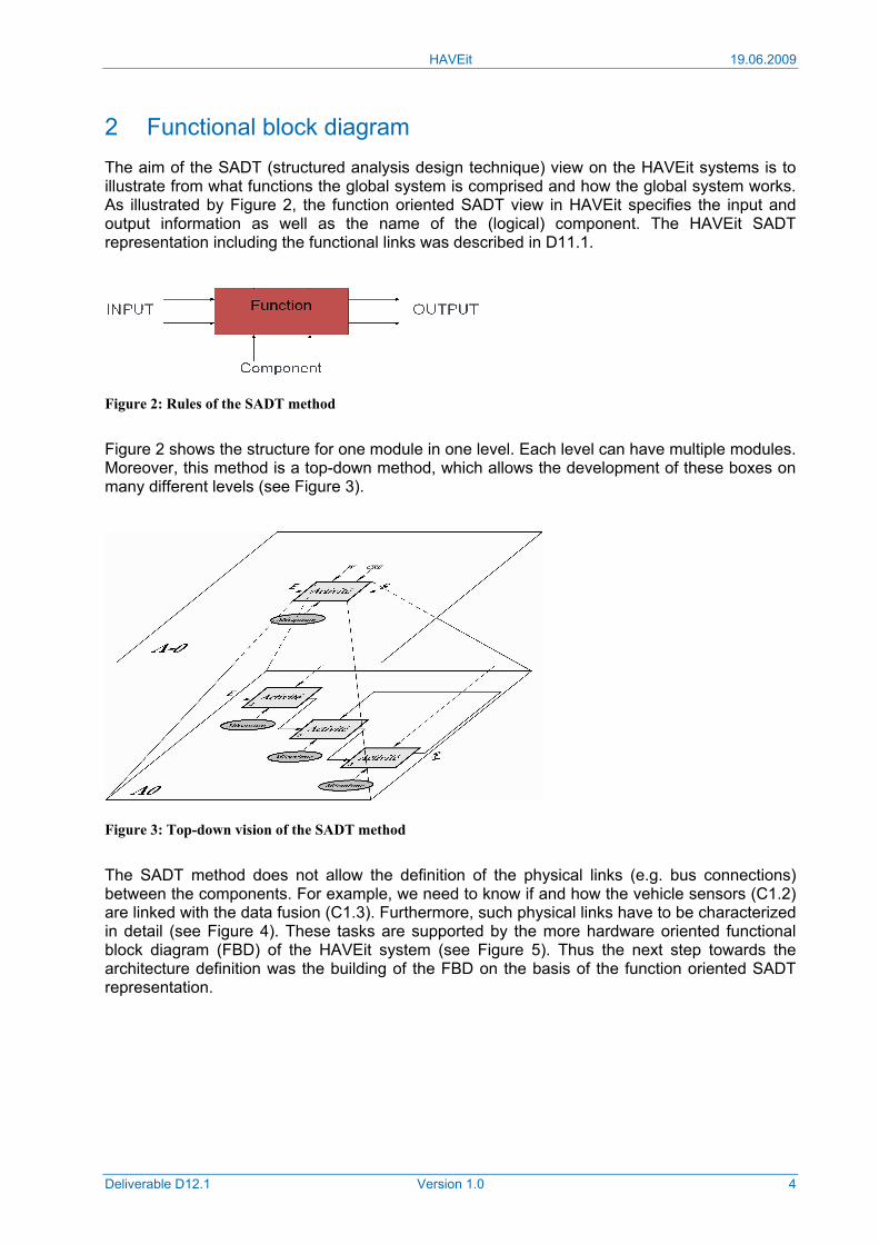
2 Functional block diagram The aim of the SADT (structured analysis design technique) view on the HAVEit systems is to illustrate from what functions the global system is comprised and how the global system works. As illustrated by Figure 2, the function oriented SADT view in HAVEit specifies the input and output information as well as the name of the (logical) component. The HAVEit SADT representation including the functional links was described in D11.1.
Figure 2: Rules of the SADT method
Figure 2 shows the structure for one module in one level. Each level can have multiple modules. Moreover, this method is a top-down method, which allows the development of these boxes on many different levels (see Figure 3).
Figure 3: Top-down vision of the SADT method
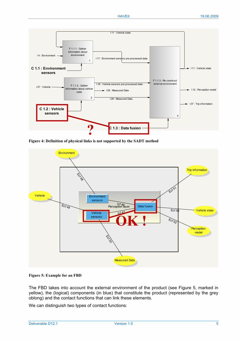
The SADT method does not allow the definition of the physical links (e.g. bus connections) between the components. For example, we need to know if and how the vehicle sensors (C1.2) are linked with the data fusion (C1.3). Furthermore, such physical links have to be characterized in detail (see Figure 4). These tasks are supported by the more hardware oriented functional block diagram (FBD) of the HAVEit system (see Figure 5). Thus the next step towards the architecture definition was the building of the FBD on the basis of the function oriented SADT representation.
HAVEit 19.06.2009
Deliverable D12.1 Version 1.0 5
I 37 : Trip information
I 28 : Measured DataI 27 : Vehicle
I 4 : Environment
I 12 : Perception model
I 11 : Vehicle state
C 1.3 : Data fusion
C 1.2 : Vehiclesensors
C 1.1 : Environmentsensors
F 1.1.1 : Gatherinformation about
environment
1
F 1.1.2 : Gatherinformation about vehicle
state
2
F 1.1.3 : Re constructexternal environment
4
I 17 : Environment sensors pre processed data
I 11 : Vehicle state
I 18 : Vehicle sensors pre processed data
I 28 : Measured Data
Figure 4: Definition of physical links is not supported by the SADT method
Perception layer
Environmentsensors
Vehiclesensors
Data fusion
Environment
Vehicle state
Perceptionmodel
Measured Data
Trip information
Icf 46
Icf 47
Ecf 48
Vehicle
Ecf 49Ecf 50
Ecf 51
Ecf 52
Ecf 53
Figure 5: Example for an FBD
The FBD takes into account the external environment of the product (see Figure 5, marked in yellow), the (logical) components (in blue) that constitute the product (represented by the grey oblong) and the contact functions that can link these elements.
We can distinguish two types of contact functions:
?
OK !
HAVEit 19.06.2009
Deliverable D12.1 Version 1.0 6
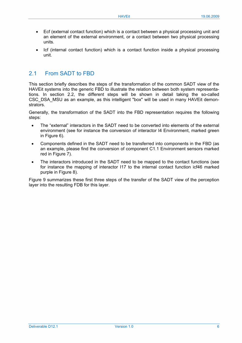
• Ecf (external contact function) which is a contact between a physical processing unit and an element of the external environment, or a contact between two physical processing units.
• Icf (internal contact function) which is a contact function inside a physical processing unit.
2.1 From SADT to FBD
This section briefly describes the steps of the transformation of the common SADT view of the HAVEit systems into the generic FBD to illustrate the relation between both system representa-tions. In section 2.2, the different steps will be shown in detail taking the so-called CSC_DSA_MSU as an example, as this intelligent "box" will be used in many HAVEit demon-strators.
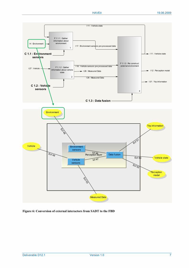
Generally, the transformation of the SADT into the FBD representation requires the following steps:
• The “external” interactors in the SADT need to be converted into elements of the external environment (see for instance the conversion of interactor I4 Environment, marked green in Figure 6).
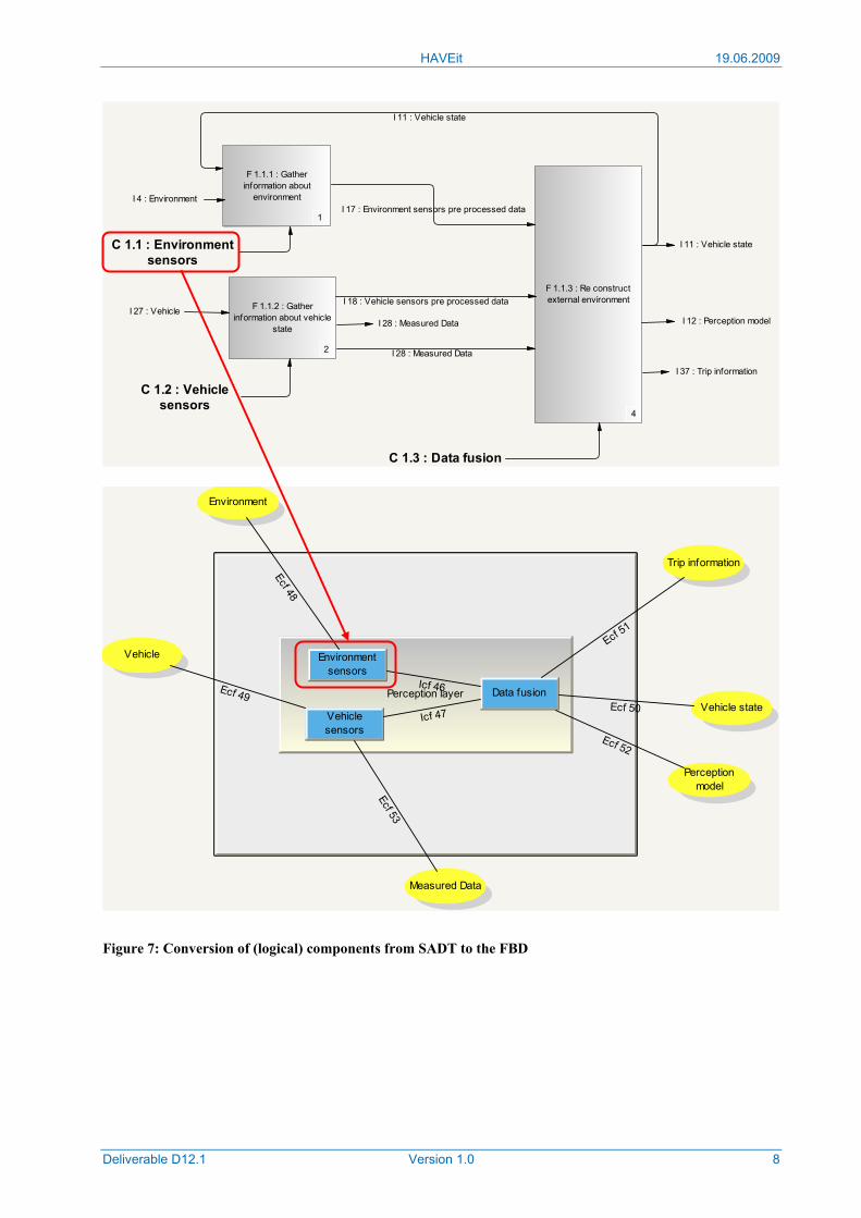
• Components defined in the SADT need to be transferred into components in the FBD (as an example, please find the conversion of component C1.1 Environment sensors marked red in Figure 7).
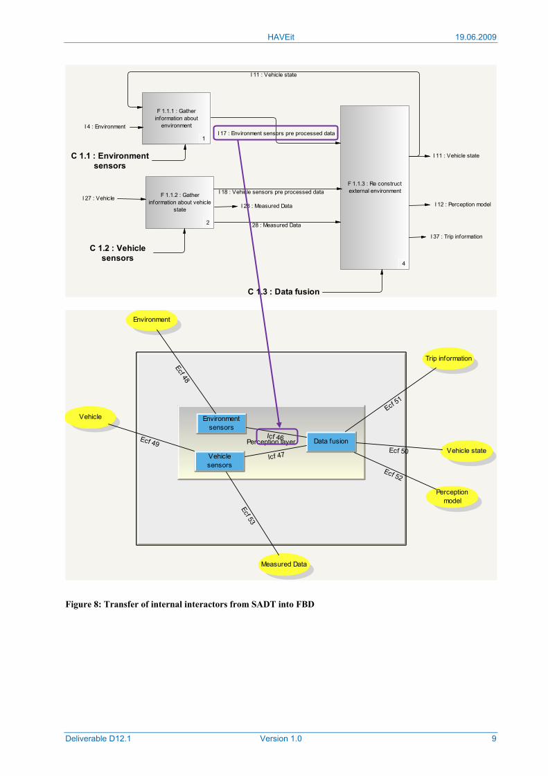
• The interactors introduced in the SADT need to be mapped to the contact functions (see for instance the mapping of interactor I17 to the internal contact function icf46 marked purple in Figure 8).
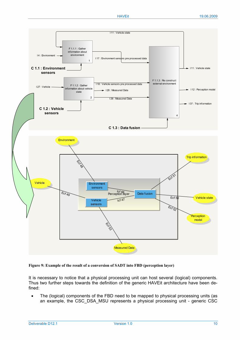
Figure 9 summarizes these first three steps of the transfer of the SADT view of the perception layer into the resulting FDB for this layer.
HAVEit 19.06.2009
Deliverable D12.1 Version 1.0 7
I 37 : Trip information
I 28 : Measured DataI 27 : Vehicle
I 4 : Environment
I 12 : Perception model
I 11 : Vehicle state
C 1.3 : Data fusion
C 1.2 : Vehiclesensors
C 1.1 : Environmentsensors
F 1.1.1 : Gatherinformation about
environment
1
F 1.1.2 : Gatherinformation about vehicle
state
2
F 1.1.3 : Re constructexternal environment
4
I 17 : Environment sensors pre processed data
I 11 : Vehicle state
I 18 : Vehicle sensors pre processed data
I 28 : Measured Data
Perception layer
Environmentsensors
Vehiclesensors
Data fusion
Environment
Vehicle state
Perceptionmodel
Measured Data
Trip information
Icf 46
Icf 47
Ecf 48
Vehicle
Ecf 49Ecf 50
Ecf 51
Ecf 52
Ecf 53
Figure 6: Conversion of external interactors from SADT to the FBD
HAVEit 19.06.2009
Deliverable D12.1 Version 1.0 8
I 37 : Trip information
I 28 : Measured DataI 27 : Vehicle
I 4 : Environment
I 12 : Perception model
I 11 : Vehicle state
C 1.3 : Data fusion
C 1.2 : Vehiclesensors
C 1.1 : Environmentsensors
F 1.1.1 : Gatherinformation about
environment
1
F 1.1.2 : Gatherinformation about vehicle
state
2
F 1.1.3 : Re constructexternal environment
4
I 17 : Environment sensors pre processed data
I 11 : Vehicle state
I 18 : Vehicle sensors pre processed data
I 28 : Measured Data
Perception layer
Environmentsensors
Vehiclesensors
Data fusion
Environment
Vehicle state
Perceptionmodel
Measured Data
Trip information
Icf 46
Icf 47
Ecf 48
Vehicle
Ecf 49Ecf 50
Ecf 51
Ecf 52
Ecf 53
Figure 7: Conversion of (logical) components from SADT to the FBD
HAVEit 19.06.2009
Deliverable D12.1 Version 1.0 9
I 37 : Trip information
I 28 : Measured DataI 27 : Vehicle
I 4 : Environment
I 12 : Perception model
I 11 : Vehicle state
C 1.3 : Data fusion
C 1.2 : Vehiclesensors
C 1.1 : Environmentsensors
F 1.1.1 : Gatherinformation about
environment
1
F 1.1.2 : Gatherinformation about vehicle
state
2
F 1.1.3 : Re constructexternal environment
4
I 17 : Environment sensors pre processed data
I 11 : Vehicle state
I 18 : Vehicle sensors pre processed data
I 28 : Measured Data
Perception layer
Environmentsensors
Vehiclesensors
Data fusion
Environment
Vehicle state
Perceptionmodel
Measured Data
Trip information
Icf 46
Icf 47
Ecf 48
Vehicle
Ecf 49Ecf 50
Ecf 51
Ecf 52
Ecf 53
Figure 8: Transfer of internal interactors from SADT into FBD
HAVEit 19.06.2009
Deliverable D12.1 Version 1.0 10
I 37 : Trip information
I 28 : Measured DataI 27 : Vehicle
I 4 : Environment
I 12 : Perception model
I 11 : Vehicle state
C 1.3 : Data fusion
C 1.2 : Vehiclesensors
C 1.1 : Environmentsensors
F 1.1.1 : Gatherinformation about
environment
1
F 1.1.2 : Gatherinformation about vehicle
state
2
F 1.1.3 : Re constructexternal environment
4
I 17 : Environment sensors pre processed data
I 11 : Vehicle state
I 18 : Vehicle sensors pre processed data
I 28 : Measured Data
Perception layer
Environmentsensors
Vehiclesensors
Data fusion
Environment
Vehicle state
Perceptionmodel
Measured Data
Trip information
Icf 46
Icf 47
Ecf 48
Vehicle
Ecf 49Ecf 50
Ecf 51
Ecf 52
Ecf 53
Figure 9: Example of the result of a conversion of SADT into FBD (perception layer)
It is necessary to notice that a physical processing unit can host several (logical) components. Thus two further steps towards the definition of the generic HAVEit architecture have been de-fined:
• The (logical) components of the FBD need to be mapped to physical processing units (as an example, the CSC_DSA_MSU represents a physical processing unit - generic CSC
HAVEit 19.06.2009
Deliverable D12.1 Version 1.0 11
ECU - that hosts the two components C2.2 Driver in the loop assessment and C2.3 Mode selection and arbitration unit).
• Having assigned the (logical) components to the physical processing units, it becomes apparent which physical processing unit needs to be connected to another. On the basis of the information to be exchanged with each interactor and the knowledge about which interactor is mapped to which external contact function, the bus load of each physical connection can be estimated and a suitable bus topology can be defined.
As the procedure is somewhat "abstract", it will be repeated in the next section which describes the development of the generic HAVEit architecture.
2.2 HAVEit generic architecture
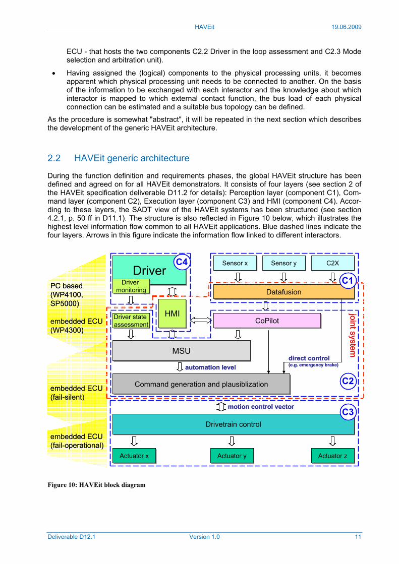
During the function definition and requirements phases, the global HAVEit structure has been defined and agreed on for all HAVEit demonstrators. It consists of four layers (see section 2 of the HAVEit specification deliverable D11.2 for details): Perception layer (component C1), Com-mand layer (component C2), Execution layer (component C3) and HMI (component C4). Accor-ding to these layers, the SADT view of the HAVEit systems has been structured (see section 4.2.1, p. 50 ff in D11.1). The structure is also reflected in Figure 10 below, which illustrates the highest level information flow common to all HAVEit applications. Blue dashed lines indicate the four layers. Arrows in this figure indicate the information flow linked to different interactors.
Figure 10: HAVEit block diagram
DriverDriverSensor xSensor x Sensor ySensor y C2XC2X
DatafusionDatafusion
CoPilotCoPilot
MSUMSU
Command generation and plausiblizationCommand generation and plausiblization
HMIHMIDriver state assessmentDriver state assessment
Drivetrain controlDrivetrain control
Actuator xActuator x Actuator yActuator y Actuator zActuator z
motion control vector
automation leveldirect control(e.g. emergency brake)
joint system
Driver monitoring
Driver monitoringPC based
(WP4100, SP5000)
embedded ECU(WP4300)
embedded ECU(fail-silent)
embedded ECU(fail-operational)
C4
C1
C2
C3
DriverDriverSensor xSensor x Sensor ySensor y C2XC2X
DatafusionDatafusion
CoPilotCoPilot
MSUMSU
Command generation and plausiblizationCommand generation and plausiblization
HMIHMIDriver state assessmentDriver state assessment
Drivetrain controlDrivetrain control
Actuator xActuator x Actuator yActuator y Actuator zActuator z
Drivetrain controlDrivetrain control
Actuator xActuator x Actuator yActuator y Actuator zActuator z
motion control vector
automation leveldirect control(e.g. emergency brake)
joint system
Driver monitoring
Driver monitoringPC based
(WP4100, SP5000)
embedded ECU(WP4300)
embedded ECU(fail-silent)
embedded ECU(fail-operational)
C4C4
C1C1
C2C2
C3C3
HAVEit 19.06.2009
Deliverable D12.1 Version 1.0 12
2.2.1 Generic FBD
The architecture migration demonstrator (WP4300) focuses on the HAVEit generic architecture implementation to demonstrate:
• Even a highly automated vehicle application (e.g. integrated longitudinal and lateral control of the vehicle with an automation level determined by HAVEit's joint system) can be realized with almost serial-like automotive ECUs.
• Thanks to the HAVEit architecture, the introduction of new functions by software means becomes more effective and easier compared with traditional vehicle architectures.
Figure 10 summarizes the key components of the HAVEit systems. The first question that arises is: Which component will be implemented and executed in which physical processing unit?
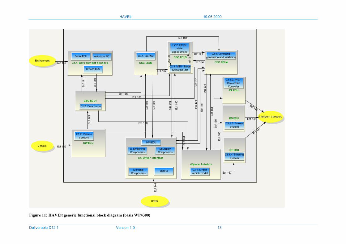
The assignment of (logical) components and sub-components to physical processing units (e.g. CSC ECU, XCC ECU, dSpace Autobox, xPC, etc.) is reflected by the (generic) functional block diagram (see Figure 11 below) generated from the HAVEit common SADT representation.
Let us take the CSC_DSA_MSU as an example: A physical processing unit is for instance re-presented by a generic CSC ECU. When we defined the common SADT view (D11.1), compo-nents and sub-components have been introduced, e.g. C2.2 DSA (a software component dedi-cated to the driver state assessment) or C2.3 MSU (a software component responsible for the automation mode selection and arbitration). Within the HAVEit consortium it was decided to implement both components, C2.2 DSA and C2.3 MSU, on a single CSC platform. The new "in-telligent" module, called CSC_DSA_MSU "CSC platform with integrated driver in the loop assessment and mode selection and arbitration unit", will be used in different HAVEit demon-strators.
According to the generic functional block diagram (Figure 11) achieved with the procedure explained in section 2.1, the WP4300 hardware architecture consists of several physical pro-cessing units (titled with green colored text). It will be mainly based on a couple of generic CSC ECUs that will be developed within this project (see D11.2, section 4.3.2).
When having decided which (logical) component is assigned to which processing unit, the second question arises: Which links exist between the different processing units? To answer this question, information has to be extracted from the SADT representation about from and to which (logical) components interactors have been introduced.
For the above mentioned example of the CSC_DSA_MSU for instance, it will be found that there is an information flow from the mode selection and arbitration unit (C2.3 MSU) to the driver state assessment (C2.2 DSA) and vice versa, thus a connection of both components needs to be planned. According to the notation in the TDC tools, this connection is called con-tact function. As this contact is located internally in the CSC ECU3 (which is responsible for both logical components), this contact function is called internal contact function (Icf 161). Furthermore, it will be noticed that the logical components C2.2 and C2.3 hosted by CSC ECU3 will exchange information with CSC ECU1 (hosting component C1.3 Data Fusion), CSC ECU2 (hosting component C2.1 Co-Pilot), HMI ECU (hosting any driver interface components) and CSC ECU4 (hosting component C2.4 Command generation and validation). Thus, contact func-tions to all physical processing units linked with CSC ECU3 have to be introduced. Please note, because these contact functions concern links outside of CSC ECU3, they are named external contact functions (Ecf 156, Ecf 162, Ecf 150 and Ecf 164 respectively).
HAVEit 19.06.2009
Deliverable D12.1 Version 1.0 13
GW ECU
Environment
Vehicle
Driver
Intelligent transport
C1.1. Environment sensors
C1.2. Vehiclesensors
Serial ECU eHorizon PC
EFKON ECU
CSC ECU1
C1.3. Data fusion
CSC ECU2
CSC ECU3
CSC ECU4
C2.1. Co-Pilot
C2.2. Driverstate
assessment
C2.3. MSU - ModeSelection Unit
C2.4. Commandgeneration and validation
C4. Driver Interface
HMI ECU
DI Sw itchingComponents
DI DisplayComponents
DI HapticComponents
DM PC
PT ECU
BS ECU
ST ECU
C3.1.2. PTC -Pow ertrainController
C3.1.3. Brakessystem
C3.1.4. Steeringsystem
Ecf 140
Ecf 141Ecf 1
41
Ecf 142
Ecf 1
43
dSpace Autobox
C3.1.1. Hostvehicle model
Ecf 1
44
Ecf 145
Ecf 146
Ecf 147
Ecf 1
49
Ecf 150 Ecf 1
50
Ecf 151
Ecf 1
51
Ecf 155Ecf 156
Ecf 1
57
Icf 1
61
Icf 161
Ecf 162
Ecf 163
Ecf 164
Ecf 164
Ecf 1
49
Ecf 167
Ecf 1
66Ec
f 165
Ecf 1
48
Ecf 160
Ecf 168
Ecf 1
68
Figure 11: HAVEit generic functional block diagram (basis WP4300)
HAVEit 19.06.2009
Deliverable D12.1 Version 1.0 14
2.2.2 Characterization of contact functions
At this stage the third question comes up: Which information is to be transferred over which contact function? This question can easily be answered again by having a look at the SADT view on the HAVEit systems (D11.1): The information flow defined by the interactors introduced in the SADT representation needs to be mapped to the previously introduced contact functions (both internal and external ones).
We again take the CSC_DSA_MSU as an example: In WP4300, this processing unit is named CSC ECU3 and hosts the logical components C2.2 and C2.3. According to Figure 32 of D11.1 (page 92), component C2.2 (Driver state assessment, hosted by CSC ECU3) receives information
• from C2.1 (Co-Pilot, CSC ECU2): Relevant targets and key environment information (interactor I7),
• from C2.3 Mode selection and arbitration unit, hosted by CSC ECU3): Current and re-quested automation level (I13),
• from C1.3 (Data Fusion, CSC ECU1): Vehicle state (I11), Trip information (I37), Percep-tion model (I12),
• from C4 (Driver interface, HMI ECU): Driver's primary task command (I10), Driver monitoring data (I6) and Driver secondary task command (I38).
According to Figure 32 of D11.1, C2.2 delivers information to component C2.3 (Mode selection and arbitration unit): Driver's distraction level (I19) and driver drowsiness level (I39).
This entails the following mapping of interactors to contact functions:
• I7 needs to be mapped to Ecf 162 (contact between CSC ECU3 and CSC ECU2)
• I13, I18 and I39 need to be mapped to Icf 161 (contact inside CSC ECU3)
• I11, I12 and I37 have to be mapped to Ecf 155 (contact between CSC ECU3 and CSC ECU1)
• I10, I6 and I38 have to be mapped to Ecf 150 (contact between CSC ECU3 and HMI ECU)
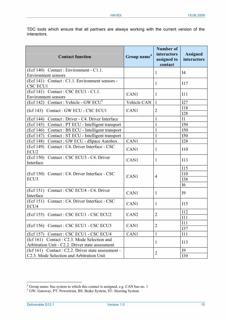
The same considerations need to be made for the information flow from and to all components defined in the SADT representation and the generic functional block diagram illustrated in Figure 11. The results of these considerations are summarized in Table 1. It includes the mapping of all interactors (right column) required for information exchange in the architecture migration demonstrator of WP4300 with the different contact functions between the physical processing units (left column).
Data to be transferred based on the previously introduced external contact functions need to be communicated via bus systems, e.g. different CAN buses. This leads to the fourth question: Which external contact functions will be physically connected with which physical bus? The assignment of the different external contact functions to suitable buses needs to be made on the basis of the busload that each of this contacts will generate.
To estimate this busload, the precise content of each Ecf, thus of each interactor (down to the level of the number of bytes per parameter and the parameter update rate) is required. Due to the high importance of the precise interactor content for the communication between the different HAVEit components, huge effort has been spent by the partners on evaluating and reaching an agreement on it. It should be noted that the interactor definition (presented in chapter 3 of this document) represents the initial state. The experience from other projects shows that during the further development and in particular during the integration phase the need to include one or the other parameter will come up. Such changes shall be tracked by the
HAVEit 19.06.2009
Deliverable D12.1 Version 1.0 15
TDC tools which ensure that all partners are always working with the current version of the interactors.
Contact function Group name4
Number of interactors assigned to
contact
Assigned interactors
(Ecf 140) Contact : Environment - C1.1. Environment sensors 1 I4
(Ecf 141) Contact : C1.1. Environment sensors - CSC ECU1 1 I17
(Ecf 141) Contact : CSC ECU1 - C1.1. Environment sensors CAN1 1 I11
(Ecf 142) Contact : Vehicle - GW ECU5 Vehicle CAN 1 I27 I18 (Icf 143) Contact : GW ECU - CSC ECU1 CAN1 2 I28
(Ecf 144) Contact : Driver - C4. Driver Interface 1 I1 (Ecf 145) Contact : PT ECU - Intelligent transport 1 I50 (Ecf 146) Contact : BS ECU - Intelligent transport 1 I50 (Ecf 147) Contact : ST ECU - Intelligent transport 1 I50 (Ecf 148) Contact : GW ECU - dSpace Autobox CAN1 1 I28 (Ecf 149) Contact : C4. Driver Interface - CSC ECU2 CAN1 1 I10
(Ecf 150) Contact : CSC ECU3 - C4. Driver Interface CAN1 1 I13
I15 I10 I38
(Ecf 150) Contact : C4. Driver Interface - CSC ECU3 CAN1 4
I6 (Ecf 151) Contact : CSC ECU4 - C4. Driver Interface CAN1 1 I9
(Ecf 151) Contact : C4. Driver Interface - CSC ECU4 CAN1 1 I15
I12 (Ecf 155) Contact : CSC ECU1 - CSC ECU2 CAN2 2 I11 I11 (Ecf 156) Contact : CSC ECU1 - CSC ECU3 CAN1 2 I37
(Ecf 157) Contact : CSC ECU1 - CSC ECU4 CAN1 1 I11 (Icf 161) Contact : C2.3. Mode Selection and Arbitration Unit - C2.2. Driver state assessment 1 I13
I9 (Icf 161) Contact : C2.2. Driver state assessment - C2.3. Mode Selection and Arbitration Unit 2 I39
4 Group name: bus system to which this contact is assigned, e.g. CAN bus no. 1 5 GW: Gateway, PT: Powertrain, BS: Brake System, ST: Steering System
HAVEit 19.06.2009
Deliverable D12.1 Version 1.0 16
Contact function Group name4
Number of interactors assigned to
contact
Assigned interactors
I30 I7 I23 I22
(Ecf 162) Contact : CSC ECU2 - CSC ECU3 CAN2 5
I10 I8 I30 (Ecf 163) Contact : CSC ECU2 - CSC ECU4 CAN2 3 I20
(Ecf 164) Contact : CSC ECU3 - CSC ECU4 CAN1 1 I13 I14 (Ecf 164) Contact : CSC ECU4 - CSC ECU3 CAN1 2 I16
(Ecf 165) Contact : dSpace Autob. - PT ECU DT6 CAN 1 I46 (Ecf 166) Contact : dSpace Autob. - BS ECU DT CAN 1 I46 (Ecf 167) Contact : dSpace Autob. - ST ECU DT CAN 1 I46
I7 I20 I8
(Ecf 149) Contact : CSC ECU2 - C4. Driver Interface CAN2 4
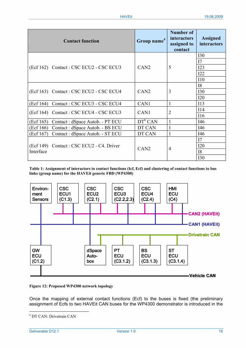
I30 Table 1: Assignment of interactors to contact functions (Icf, Ecf) and clustering of contact functions to bus links (group name) for the HAVEit generic FBD (WP4300)
Figure 12: Proposed WP4300 network topology
Once the mapping of external contact functions (Ecf) to the buses is fixed (the preliminary assignment of Ecfs to two HAVEit CAN buses for the WP4300 demonstrator is introduced in the 6 DT CAN: Drivetrain CAN
CSCECU1(C1.3)
GWECU(C1.2)
CSCECU2(C2.1)
CSCECU3(C2.2,2.3)
CSCECU4(C2.4)
Environ-mentSensors
HMIECU(C4)
dSpaceAuto-box
PTECU(C3.1.2)
BSECU(C3.1.3)
STECU(C3.1.4)
Vehicle CAN
CAN1 (HAVEit)
Drivetrain CAN
CAN2 (HAVEit)
CSCECU1(C1.3)
CSCECU1(C1.3)
GWECU(C1.2)
GWECU(C1.2)
CSCECU2(C2.1)
CSCECU2(C2.1)
CSCECU3(C2.2,2.3)
CSCECU3(C2.2,2.3)
CSCECU4(C2.4)
CSCECU4(C2.4)
Environ-mentSensors
Environ-mentSensors
HMIECU(C4)
HMIECU(C4)
dSpaceAuto-box
dSpaceAuto-box
PTECU(C3.1.2)
PTECU(C3.1.2)
BSECU(C3.1.3)
BSECU(C3.1.3)
STECU(C3.1.4)
STECU(C3.1.4)
Vehicle CAN
CAN1 (HAVEit)
Drivetrain CAN
CAN2 (HAVEit)
HAVEit 19.06.2009
Deliverable D12.1 Version 1.0 17
second column of Table 1 above), the network topology for the vehicle is determined, which can be interpreted as the fifth question in the generic architecture definition process. Internal contact functions will not cause traffic on the bus system, thus they can be neglected for the bus load estimation. Internal data rates can be very high, thus they will not cause any transfer problems. A proposal for a network topology for the WP4300 demonstrator is given in Figure 12.
2.3 Vehicle specific adaptations
This section covers the demonstrator specific adaptations of the generic functional block dia-gram. For reasons of simplicity, only the external contact functions relevant for the determina-tion of bus loads are listed for each SP5000 demonstrator.
It should be noted that WP4100 is based on the generic FBD, but due to its nature as rapid prototyping system, it is realized largely on a PC. Thus there is no need to add an additional section for the joint system interaction for this vehicle.
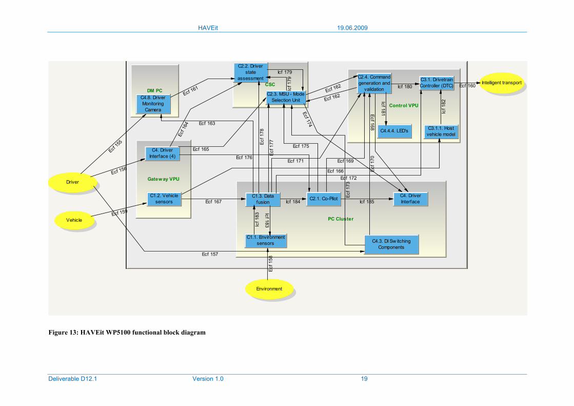
2.3.1 Automated roadwork assistance FBD
Figure 13 shows the specific functional block diagram (FBD) of the HAVEit system, as it will be implemented in the automated roadwork assistance demonstrator of WP5100. The FBD con-tains the physical components of the system, the so-called processing units (grey boxes). Therein the logical components (blue boxes) are enclosed. The communication between these logical components is described by internal contact functions (Icfs), whereas the communication between the different processing units of the whole system is described by external contact functions (Ecfs).
The WP5100 specific HAVEit system uses the logical components of the HAVEit joint system, which are specified in the deliverable D11.2 and were already referred to in the description of the generic FBD in this chapter. However, compared with the generic FBD, some components are mapped in different physical processing units. As these are specific to the WP5100 system, they will be described in the following in greater detail.
Physical processing units
From the hardware point of view, the physical components of the WP5100 system will be realized by ECUs and automotive PCs (amongst others due to the huge amount of data pro-cessing capability that is required for the low level fusion of video and radar raw data). Apart from the CSC ECU (generic Chassis and Safety Controller), which is going to be developed within the HAVEit subproject SP2000, another ECU, which is already existing and proofed, will be used to realize basic functionalities, which have to be available in the demonstration vehicle very early. This ECU is called VPU (Versatile Processing Unit).
Gateway VPU
The physical component Gateway VPU provides the gateway to the serial vehicle CAN bus exchanging information between the vehicle CAN and the assigned logical components. Accor-ding to these components, this information concerns the vehicle sensor data (C1.2), the primary driving commands (C4.2) and the haptic signals (C4.6).
Remark: In the FBD, the logical components C4.2 and C4.6 of the Gateway VPU are pooled in the logical component “C4 Driver Interface”.

HAVEit 19.06.2009
Deliverable D12.1 Version 1.0 18
PC Cluster
This physical component consists of several clustered automotive PCs that share the most intensive computational tasks of the system like gathering the measured data from the environ-ment sensors (C1.1), fusing this environment data to create the complete perception model (C1.3) and finally, performing the co-pilot functionality with this information (C2.1) by calculating the feasible trajectory.
Beyond that, the HAVEit specific input of the driver (C4.3) like pushing the HAVEit button, will be managed by this component as well as the output of the primary display (C4.4.1), the secon-dary display (C4.4.2) and the audio components (C4.5).
Remark: In the FBD, the logical components C4.4.1, C4.4.2 and C4.5 of the PC Cluster are pooled in the logical component “C4 Driver Interface”.
CSC
The physical component CSC is identical to the physical component CSC ECU3 of the generic FBD in the previous section. It contains the logical components DSA (C2.2, Driver state assessment) and MSU (C2.3, Mode selection and arbitration unit) and will be used in most of the HAVEit demonstration vehicles in the same way.
DM PC
This automotive PC contains the image processing application of the direct driver monitoring system (C4.8). It evaluates the image data of a camera that is monitoring the driver. It is a com-putationally intensive application that also needs the processing power and the storage capa-cities of a PC. Similar to the CSC, the DM PC is a commonly used physical component that will be integrated in several HAVEit applications.
Control VPU
The main functionality of the Control VPU is to transform the trajectory calculated by the co-pilot into a longitudinal and lateral motion demand (C2.4) in order to control the longitudinal motion (C3.1.2 + C3.1.3) and the lateral motion (C3.1.4) of the vehicle, using the dynamic vehicle model (C3.1.1). Additionally, the LED output (C4.4.4) indicating critical lane changes and the availability state of the longitudinal and lateral controller will be managed directly by this physi-cal component.
Remark: In the FBD, the logical components C3.1.2, C3.1.3 and C3.1.4 are pooled in the logical component “C3.1. Drivetrain Controller (DTC)”.
HAVEit 19.06.2009
Deliverable D12.1 Version 1.0 19
Environment
Vehicle
Driver
Intelligent transport
PC Cluster
Gateway VPU
Control VPU
DM PCCSC
C1.1. Environmentsensors
C1.3. Datafusion
C2.1. Co-Pilot
C4.3. DI Sw itchingComponents
C4. DriverInterface
C4. DriverInterface (4)
C1.2. Vehiclesensors
C2.4. Commandgeneration and
validation
C3.1.1. Hostvehicle model
C3.1. DrivetrainController (DTC)
C4.4.4. LED's
C2.2. Driverstate
assessment
C2.3. MSU - ModeSelection UnitC4.8. Driver
MonitoringCamera
Ecf 15
5
Ecf 156
Ecf 157
Ecf 1
58
Ecf 159
Ecf 160
Ecf 161 Ecf 162
Ecf 162
Ecf 163
Ecf 1
64
Ecf 165
Ecf 166
Ecf 167Ecf 168
Ecf 169
Ecf 1
70Ecf 171
Ecf 172
Ecf 1
73
Ecf 174
Ecf 175
Ecf 176
Ecf 1
77Ecf 1
78
Icf 179
Icf 1
79
Icf 180
Icf 181 Icf 1
82
Icf 183Icf 1
83
Icf 184 Icf 185
Figure 13: HAVEit WP5100 functional block diagram
HAVEit 19.06.2009
Deliverable D12.1 Version 1.0 20
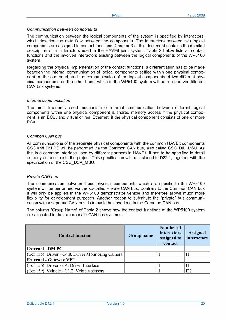
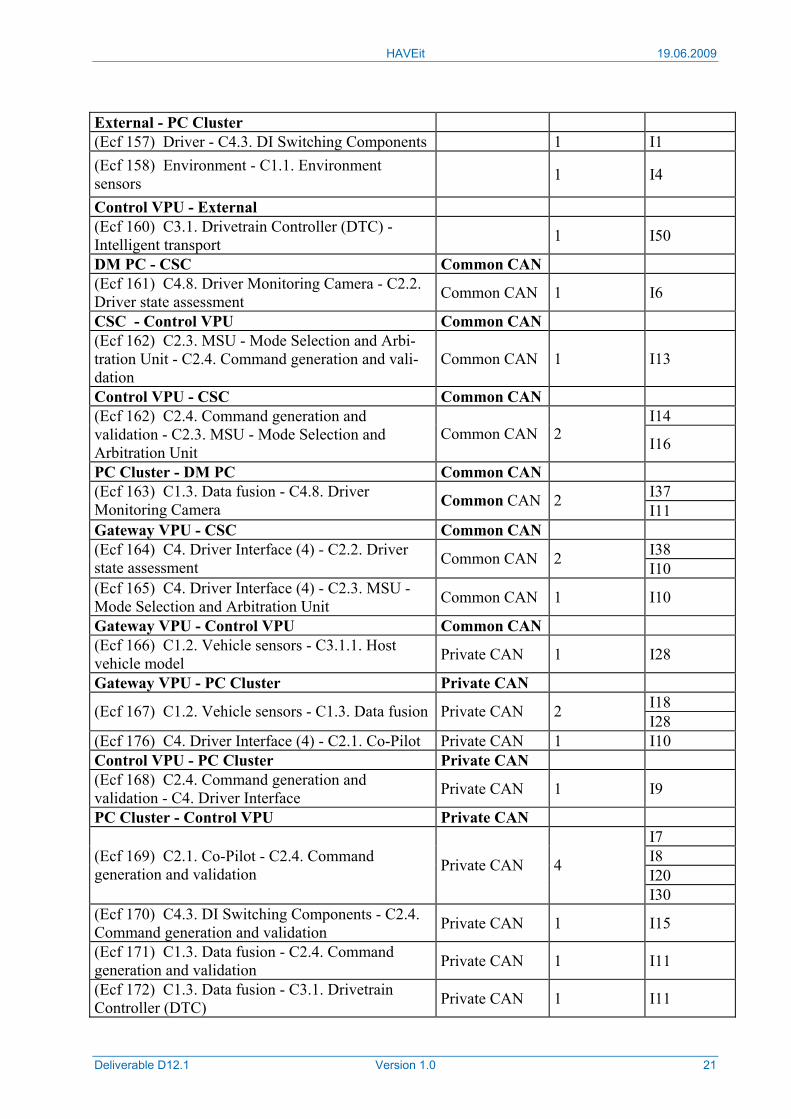
Communication between components
The communication between the logical components of the system is specified by interactors, which describe the data flow between the components. The interactors between two logical components are assigned to contact functions. Chapter 3 of this document contains the detailed description of all interactors used in the HAVEit joint system. Table 2 below lists all contact functions and the involved interactors existing between the logical components of the WP5100 system.
Regarding the physical implementation of the contact functions, a differentiation has to be made between the internal communication of logical components settled within one physical compo-nent on the one hand, and the communication of the logical components of two different phy-sical components on the other hand, which in the WP5100 system will be realized via different CAN bus systems.
Internal communication
The most frequently used mechanism of internal communication between different logical components within one physical component is shared memory access if the physical compo-nent is an ECU, and virtual or real Ethernet, if the physical component consists of one or more PCs.
Common CAN bus
All communications of the separate physical components with the common HAVEit components CSC and DM PC will be performed via the Common CAN bus, also called CSC_DIL_MSU. As this is a common interface used by different partners in HAVEit, it has to be specified in detail as early as possible in the project. This specification will be included in D22.1, together with the specification of the CSC_DSA_MSU.
Private CAN bus
The communication between those physical components which are specific to the WP5100 system will be performed via the so-called Private CAN bus. Contrary to the Common CAN bus it will only be applied in the WP5100 demonstrator vehicle and therefore allows much more flexibility for development purposes. Another reason to substitute the “private” bus communi-cation with a separate CAN bus, is to avoid bus overload in the Common CAN bus.
The column "Group Name" of Table 2 shows how the contact functions of the WP5100 system are allocated to their appropriate CAN bus systems.
Contact function Group name
Number of interactors assigned to
contact
Assigned interactors
External - DM PC (Ecf 155) Driver - C4.8. Driver Monitoring Camera 1 I1 External - Gateway VPU (Ecf 156) Driver - C4. Driver Interface 1 I1 (Ecf 159) Vehicle - C1.2. Vehicle sensors 1 I27
HAVEit 19.06.2009
Deliverable D12.1 Version 1.0 21
External - PC Cluster (Ecf 157) Driver - C4.3. DI Switching Components 1 I1 (Ecf 158) Environment - C1.1. Environment sensors 1 I4
Control VPU - External (Ecf 160) C3.1. Drivetrain Controller (DTC) - Intelligent transport 1 I50
DM PC - CSC Common CAN (Ecf 161) C4.8. Driver Monitoring Camera - C2.2. Driver state assessment Common CAN 1 I6
CSC - Control VPU Common CAN (Ecf 162) C2.3. MSU - Mode Selection and Arbi-tration Unit - C2.4. Command generation and vali-dation
Common CAN 1 I13
Control VPU - CSC Common CAN I14 (Ecf 162) C2.4. Command generation and
validation - C2.3. MSU - Mode Selection and Arbitration Unit
Common CAN 2 I16
PC Cluster - DM PC Common CAN I37 (Ecf 163) C1.3. Data fusion - C4.8. Driver
Monitoring Camera Common CAN 2 I11 Gateway VPU - CSC Common CAN
I38 (Ecf 164) C4. Driver Interface (4) - C2.2. Driver state assessment Common CAN 2 I10 (Ecf 165) C4. Driver Interface (4) - C2.3. MSU - Mode Selection and Arbitration Unit Common CAN 1 I10
Gateway VPU - Control VPU Common CAN (Ecf 166) C1.2. Vehicle sensors - C3.1.1. Host vehicle model Private CAN 1 I28
Gateway VPU - PC Cluster Private CAN I18 (Ecf 167) C1.2. Vehicle sensors - C1.3. Data fusion Private CAN 2 I28
(Ecf 176) C4. Driver Interface (4) - C2.1. Co-Pilot Private CAN 1 I10 Control VPU - PC Cluster Private CAN (Ecf 168) C2.4. Command generation and validation - C4. Driver Interface Private CAN 1 I9
PC Cluster - Control VPU Private CAN I7 I8 I20
(Ecf 169) C2.1. Co-Pilot - C2.4. Command generation and validation Private CAN 4
I30 (Ecf 170) C4.3. DI Switching Components - C2.4. Command generation and validation Private CAN 1 I15
(Ecf 171) C1.3. Data fusion - C2.4. Command generation and validation Private CAN 1 I11
(Ecf 172) C1.3. Data fusion - C3.1. Drivetrain Controller (DTC) Private CAN 1 I11
HAVEit 19.06.2009
Deliverable D12.1 Version 1.0 22
CSC - PC Cluster Common CAN (Ecf 174) C2.3. MSU - Mode Selection and Arbitration Unit - C4. Driver Interface Common CAN 1 I13
PC Cluster - CSC Common CAN (Ecf 173) C4.3. DI Switching Components - C2.3. MSU - Mode Selection and Arbitration Unit Common CAN 1 I15
I7 I20 I22 I23
(Ecf 175) C2.1. Co-Pilot - C2.3. MSU - Mode Selection Unit Common CAN 5
I30 (Ecf 177) C1.3. Data fusion - C2.3. MSU - Mode Selection and Arbitration Unit Common CAN 1 I11
I11 (Ecf 178) C1.3. Data fusion - C2.2. Driver state assessment Common CAN 2 I37 CSC internal
I19 (Icf 179) C2.2. Driver state assessment - C2.3. MSU - Mode Selection Unit 2 I39 (Icf 179) C2.3. MSU - Mode Selection and Arbitration Unit - C2.2. Driver state assessment 1 I13
Control VPU internal (Icf 180) C2.4. Command generation and validation - C3.1. Drivetrain Controller (DTC) 1 I25
(Icf 181) C2.4. Command generation and validation - C4.4.4. LEDs 1 I9
(Icf 182) C3.1.1. Host vehicle model - C3.1. Drivetrain Controller (DTC) 1 I46
PC Cluster internal (Icf 183) C1.3. Data fusion - C1.1. Environment sensors 1 I11
(Icf 183) C1.1. Environment sensors - C1.3. Data fusion 1 I17
I11 (Icf 184) C1.3. Data fusion - C2.1. Co-Pilot 2 I12 I7 I8 I20 (Icf 185) C2.1. Co-Pilot - C4. Driver Interface 4
I30
Table 2: Assignment of interactors to contact functions (Icf, Ecf) and clustering of contact functions to bus links (group name) for the WP5100 demonstrator On the basis of the WP5100 specific assignment of logical components to physical processing units (Figure 14), the interactors to be transferred between the different processing units can be summarized (Table 3).
HAVEit 19.06.2009
Deliverable D12.1 Version 1.0 23
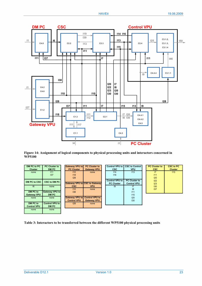
Figure 14: Assignment of logical components to physical processing units and interactors concerned in WP5100
DM PC to PC Cluster
PC Cluster to DM PC
Gateway VPU to PC Cluster
PC Cluster to Gateway VPU
Control VPU to CSC
CSC to Control VPU
PC Cluster to CSC
CSC to PC Cluster
none I11 I10 none I14 I13 I7 I13I37 I18 I16 I11
I28 I20I22I23
I6 none I9 I7 I30I10 none I8 I37I38 I11
I15none none I20
I30I28 none
none none
Gateway VPU to CSC
CSC to Gateway VPU
DM PC to Gateway VPU
Gateway VPU to DM PC
DM PC to CSC CSC to DM PC
DM PC to Control VPU
Control VPU to DM PC
Control VPU to PC Cluster
PC Cluster to Control VPU
Gateway VPU to Control VPU
Control VPU to Gateway VPU
Table 3: Interactors to be transferred between the different WP5100 physical processing units
C1.1
C1.3
C3.1.2,
C3.1.3,
C3.1.4
C2.4
I4
I46
I50
PC Cluster
C2.1
C4.8
I7I8I20I30
C2.3C2.2
I39
I13
I19
I6
C4.2
C4.6
C1.2
I7 I20I8 I30
Gateway VPU
I27
I18 I11
I17
I28
I12
I10
C4.4.4
I38
I1
I15
I11
C4.3
I1
I15
I37
C4.4.1
C4.4.2
C4.5
I7
I25
I9
I28
I10
I9
I7
I1
I13
I13
I20I22I23I30
I11I37
I11
I11
I14 I16
I11
C3.1.1
Control VPUDM PC CSC
HAVEit 19.06.2009
Deliverable D12.1 Version 1.0 24
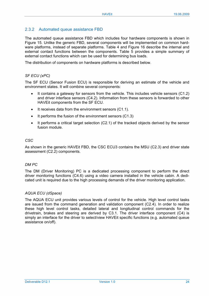
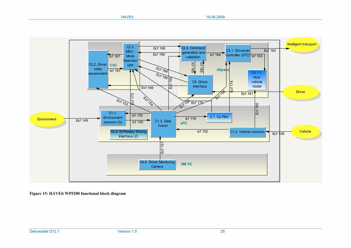
2.3.2 Automated queue assistance FBD
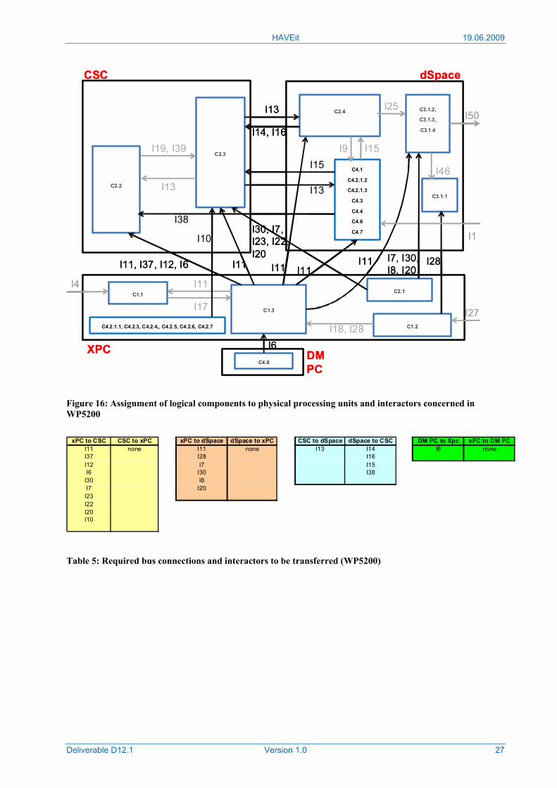
The automated queue assistance FBD which includes four hardware components is shown in Figure 15. Unlike the generic FBD, several components will be implemented on common hard-ware platforms, instead of separate platforms. Table 4 and Figure 16 describe the internal and external contact functions between the components. Table 5 provides a simple summary of external contact functions which can be used for determining bus loads.
The distribution of components on hardware platforms is described below.
SF ECU (xPC)
The SF ECU (Sensor Fusion ECU) is responsible for deriving an estimate of the vehicle and environment states. It will combine several components:
• It contains a gateway for sensors from the vehicle. This includes vehicle sensors (C1.2) and driver interface sensors (C4.2). Information from these sensors is forwarded to other HAVEit components from the SF ECU.
• It receives data from the environment sensors (C1.1).
• It performs the fusion of the environment sensors (C1.3)
• It performs a critical target selection (C2.1) of the tracked objects derived by the sensor fusion module.
CSC
As shown in the generic HAVEit FBD, the CSC ECU3 contains the MSU (C2.3) and driver state assessment (C2.2) components.
DM PC
The DM (Driver Monitoring) PC is a dedicated processing component to perform the direct driver monitoring functions (C4.6) using a video camera installed in the vehicle cabin. A dedi-cated unit is required due to the high processing demands of the driver monitoring application.
AQUA ECU (dSpace)
The AQUA ECU unit provides various levels of control for the vehicle. High level control tasks are issued from the command generation and validation component (C2.4). In order to realize these high level control tasks, detailed lateral and longitudinal control commands for the drivetrain, brakes and steering are derived by C3.1. The driver interface component (C4) is simply an interface for the driver to select/view HAVEit specific functions (e.g. automated queue assistance on/off).
HAVEit 19.06.2009
Deliverable D12.1 Version 1.0 25
Environment
Vehicle
Driver
Intelligent transport
xPC
CSCdSpace
DM PC
C2.2. Driverstate
assessment
C2.3.MSU -Mode
SelectionUnit
C2.4. Commandgeneration and
validation
C3.1. DrivetrainController (DTC)
C4. DriverInterface
C4.8. Driver MonitoringCamera
C1.3. Datafusion
C1.2. Vehicle sensors
C1.1.Environmentsensors (5)
C3.1.1.Host
vehiclemodel
Ecf 148
Ecf 149 Icf 150
Icf 150
Ecf 1
51
Icf 152
Ecf 153
Ecf 154
Ecf 1
55
Ecf 156Ecf
158
Ecf 1
60
Ecf 161
Ecf 162Icf 163Icf 164
Icf 165
Icf 165
Ecf 166
Ecf 166
Icf 167
Icf 167
Ecf 168Ecf 168
Ecf 169
C4.2. DI Primary DrivingInterface (2)
2.1. Co-Pilot
Ecf 1
73
Ecf 1
74
Ecf 175
Icf 176
Figure 15: HAVEit WP5200 functional block diagram
HAVEit 19.06.2009
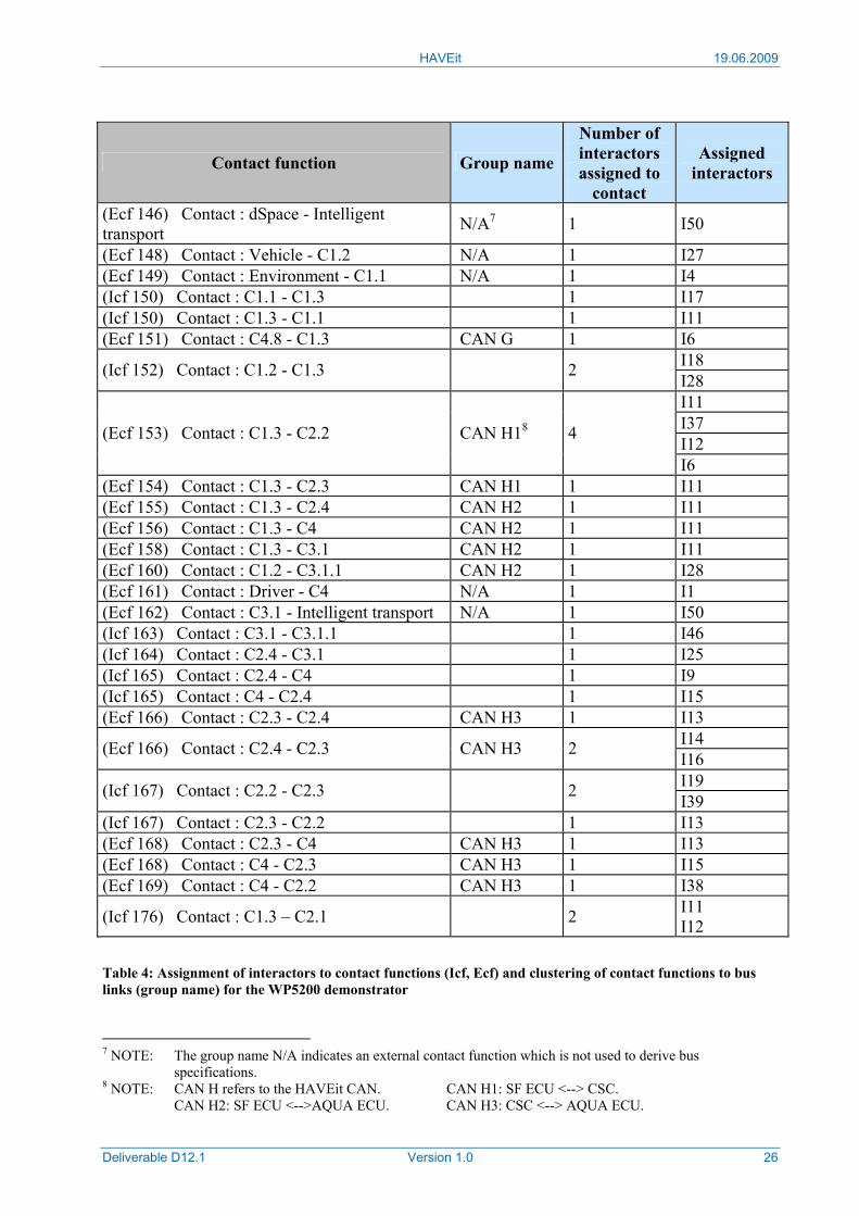
Deliverable D12.1 Version 1.0 26
Contact function Group name
Number of interactors assigned to
contact
Assigned interactors
(Ecf 146) Contact : dSpace - Intelligent transport N/A7 1 I50
(Ecf 148) Contact : Vehicle - C1.2 N/A 1 I27 (Ecf 149) Contact : Environment - C1.1 N/A 1 I4 (Icf 150) Contact : C1.1 - C1.3 1 I17 (Icf 150) Contact : C1.3 - C1.1 1 I11 (Ecf 151) Contact : C4.8 - C1.3 CAN G 1 I6
I18 (Icf 152) Contact : C1.2 - C1.3 2 I28 I11 I37 I12 (Ecf 153) Contact : C1.3 - C2.2 CAN H18 4
I6 (Ecf 154) Contact : C1.3 - C2.3 CAN H1 1 I11 (Ecf 155) Contact : C1.3 - C2.4 CAN H2 1 I11 (Ecf 156) Contact : C1.3 - C4 CAN H2 1 I11 (Ecf 158) Contact : C1.3 - C3.1 CAN H2 1 I11 (Ecf 160) Contact : C1.2 - C3.1.1 CAN H2 1 I28 (Ecf 161) Contact : Driver - C4 N/A 1 I1 (Ecf 162) Contact : C3.1 - Intelligent transport N/A 1 I50 (Icf 163) Contact : C3.1 - C3.1.1 1 I46 (Icf 164) Contact : C2.4 - C3.1 1 I25 (Icf 165) Contact : C2.4 - C4 1 I9 (Icf 165) Contact : C4 - C2.4 1 I15 (Ecf 166) Contact : C2.3 - C2.4 CAN H3 1 I13
I14 (Ecf 166) Contact : C2.4 - C2.3 CAN H3 2 I16 I19 (Icf 167) Contact : C2.2 - C2.3 2 I39
(Icf 167) Contact : C2.3 - C2.2 1 I13 (Ecf 168) Contact : C2.3 - C4 CAN H3 1 I13 (Ecf 168) Contact : C4 - C2.3 CAN H3 1 I15 (Ecf 169) Contact : C4 - C2.2 CAN H3 1 I38
(Icf 176) Contact : C1.3 – C2.1 2 I11 I12
Table 4: Assignment of interactors to contact functions (Icf, Ecf) and clustering of contact functions to bus links (group name) for the WP5200 demonstrator
7 NOTE: The group name N/A indicates an external contact function which is not used to derive bus specifications. 8 NOTE: CAN H refers to the HAVEit CAN. CAN H1: SF ECU <--> CSC. CAN H2: SF ECU <-->AQUA ECU. CAN H3: CSC <--> AQUA ECU.
HAVEit 19.06.2009
Deliverable D12.1 Version 1.0 27
Figure 16: Assignment of logical components to physical processing units and interactors concerned in WP5200
xPC to CSC CSC to xPC xPC to dSpace dSpace to xPC CSC to dSpace dSpace to CSC DM PC to Xpc xPC to DM PCI11 none I11 none I13 I14 I6 noneI37 I28 I16I12 I7 I15I6 I30 I38
I30 I8I7 I20
I23I22I20I10
Table 5: Required bus connections and interactors to be transferred (WP5200)
C1.1
C1.2
C1.3
C2.3
C2.2
C3.1.1
C3.1.2,
C3.1.3,
C3.1.4
C2.4
C4.1
C4.2.1.2
C4.2.1.3
C4.3
C4.4
C4.6
C4.7
I4
I27
I11
I17
I18, I28
I28I11I11 I11I11, I37, I12, I6 I11
I19, I39
I13
I15
I13
I13
I14, I16
I38
I9 I15
I25
I46
I50
CSC dSpace
XPC
I1
C4.8
C4.2.1.1, C4.2.3, C4.2.4,, C4.2.5, C4.2.6, C4.2.7
I6DM PC
I10
C2.1
I7, I30,I8, I20
I30, I7, I23, I22, I20
HAVEit 19.06.2009
Deliverable D12.1 Version 1.0 28
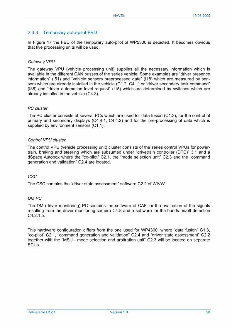
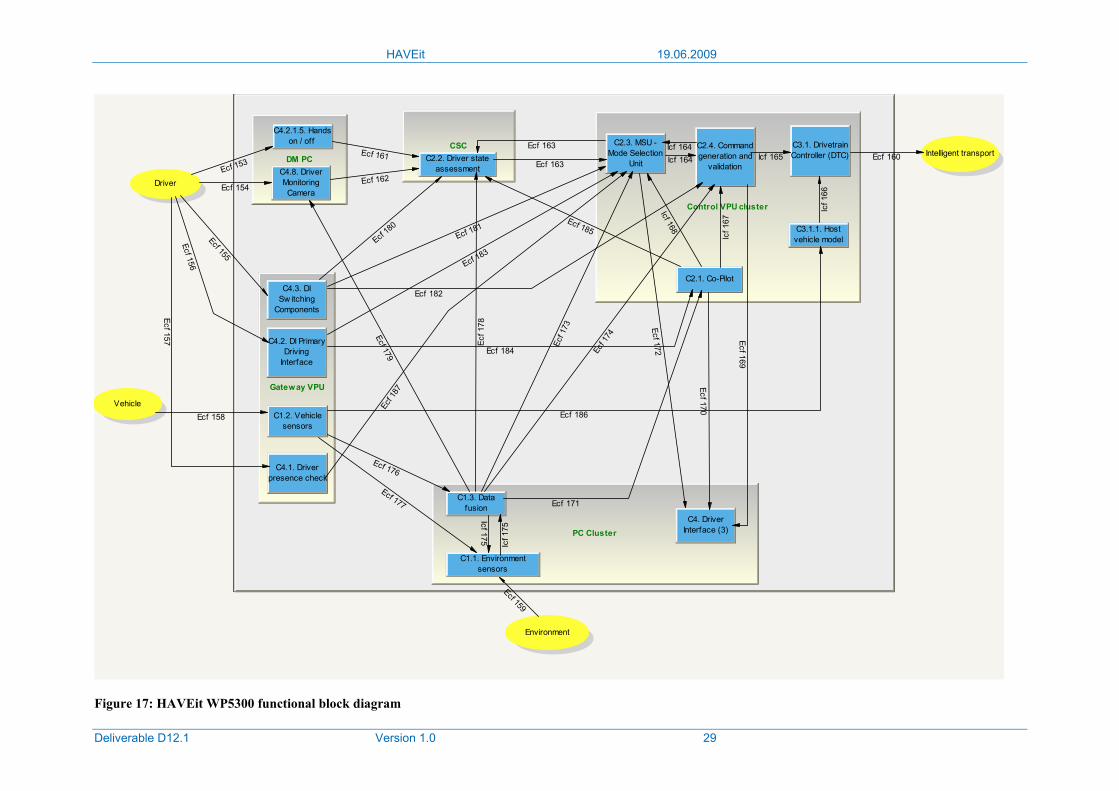
2.3.3 Temporary auto-pilot FBD
In Figure 17 the FBD of the temporary auto-pilot of WP5300 is depicted. It becomes obvious that five processing units will be used:
Gateway VPU
The gateway VPU (vehicle processing unit) supplies all the necessary information which is available in the different CAN busses of the series vehicle. Some examples are “driver presence information” (I51) and “vehicle sensors preprocessed data” (I18) which are measured by sen-sors which are already installed in the vehicle (C1.2, C4.1) or “driver secondary task command” (I38) and “driver automation level request” (I15) which are determined by switches which are already installed in the vehicle (C4.3).
PC cluster
The PC cluster consists of several PCs which are used for data fusion (C1.3), for the control of primary and secondary displays (C4.4.1, C4.4.2) and for the pre-processing of data which is supplied by environment sensors (C1.1).
Control VPU cluster
The control VPU (vehicle processing unit) cluster consists of the series control VPUs for power-train, braking and steering which are subsumed under “drivetrain controller (DTC)” 3.1 and a dSpace Autobox where the “co-pilot” C2.1, the “mode selection unit” C2.3 and the “command generation and validation” C2.4 are located.
CSC
The CSC contains the “driver state assessment” software C2.2 of WIVW.
DM PC
The DM (driver monitoring) PC contains the software of CAF for the evaluation of the signals resulting from the driver monitoring camera C4.8 and a software for the hands on/off detection C4.2.1.5.
This hardware configuration differs from the one used for WP4300, where “data fusion” C1.3, “co-pilot” C2.1, “command generation and validation” C2.4 and “driver state assessment” C2.2 together with the “MSU - mode selection and arbitration unit” C2.3 will be located on separate ECUs.
HAVEit 19.06.2009
Deliverable D12.1 Version 1.0 29
Environment
Vehicle
Driver
Intelligent transportDM PC
CSC
Control VPU cluster
PC Cluster
Gateway VPU
C1.2. Vehiclesensors
C4.1. Driverpresence check
C4.2. DI PrimaryDriving
Interface
C4.3. DISw itching
Components
C1.1. Environmentsensors
C1.3. Datafusion
C4. DriverInterface (3)
C2.1. Co-Pilot
C2.3. MSU -Mode Selection
Unit
C2.4. Commandgeneration and
validation
C3.1. DrivetrainController (DTC)
C3.1.1. Hostvehicle model
C2.2. Driver stateassessmentC4.8. Driver
MonitoringCamera
C4.2.1.5. Handson / off
Ecf 153
Ecf 154
Ecf 155
Ecf 156
Ecf 157
Ecf 158
Ecf 159
Ecf 160Ecf 161
Ecf 162
Ecf 163
Ecf 163
Icf 164Icf 164
Icf 165
Icf 1
66
Icf 1
67
Icf 168
Ecf 169
Ecf 170
Ecf 171
Ecf 172Ecf 1
73
Ecf 1
74
Icf 175
Icf 1
75
Ecf 176
Ecf 177
Ecf 1
78
Ecf 179
Ecf 18
0Ecf 181
Ecf 182
Ecf 183
Ecf 184
Ecf 185
Ecf 186
Ecf 1
87
Figure 17: HAVEit WP5300 functional block diagram
HAVEit 19.06.2009
Deliverable D12.1 Version 1.0 30
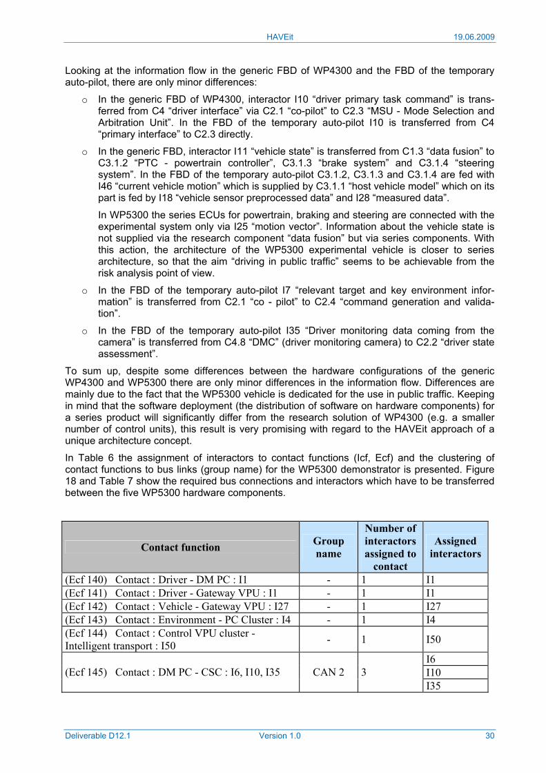
Looking at the information flow in the generic FBD of WP4300 and the FBD of the temporary auto-pilot, there are only minor differences:
o In the generic FBD of WP4300, interactor I10 “driver primary task command” is trans-ferred from C4 “driver interface” via C2.1 “co-pilot” to C2.3 “MSU - Mode Selection and Arbitration Unit”. In the FBD of the temporary auto-pilot I10 is transferred from C4 “primary interface” to C2.3 directly.
o In the generic FBD, interactor I11 “vehicle state” is transferred from C1.3 “data fusion” to C3.1.2 “PTC - powertrain controller”, C3.1.3 “brake system” and C3.1.4 “steering system”. In the FBD of the temporary auto-pilot C3.1.2, C3.1.3 and C3.1.4 are fed with I46 “current vehicle motion” which is supplied by C3.1.1 “host vehicle model” which on its part is fed by I18 “vehicle sensor preprocessed data” and I28 “measured data”.
In WP5300 the series ECUs for powertrain, braking and steering are connected with the experimental system only via I25 “motion vector”. Information about the vehicle state is not supplied via the research component “data fusion” but via series components. With this action, the architecture of the WP5300 experimental vehicle is closer to series architecture, so that the aim “driving in public traffic” seems to be achievable from the risk analysis point of view.
o In the FBD of the temporary auto-pilot I7 “relevant target and key environment infor-mation” is transferred from C2.1 “co - pilot” to C2.4 “command generation and valida-tion”.
o In the FBD of the temporary auto-pilot I35 “Driver monitoring data coming from the camera” is transferred from C4.8 “DMC” (driver monitoring camera) to C2.2 “driver state assessment”.
To sum up, despite some differences between the hardware configurations of the generic WP4300 and WP5300 there are only minor differences in the information flow. Differences are mainly due to the fact that the WP5300 vehicle is dedicated for the use in public traffic. Keeping in mind that the software deployment (the distribution of software on hardware components) for a series product will significantly differ from the research solution of WP4300 (e.g. a smaller number of control units), this result is very promising with regard to the HAVEit approach of a unique architecture concept.
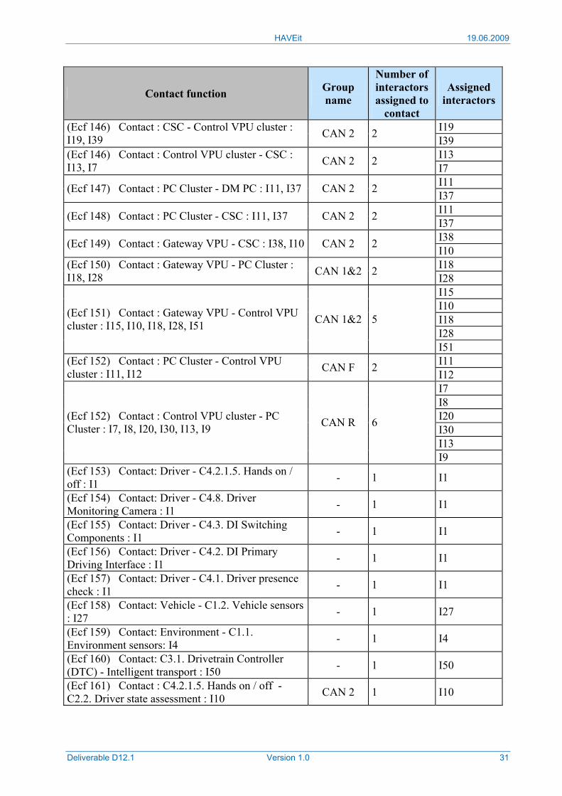
In Table 6 the assignment of interactors to contact functions (Icf, Ecf) and the clustering of contact functions to bus links (group name) for the WP5300 demonstrator is presented. Figure 18 and Table 7 show the required bus connections and interactors which have to be transferred between the five WP5300 hardware components.
Contact function Group name
Number of interactors assigned to
contact
Assigned interactors
(Ecf 140) Contact : Driver - DM PC : I1 - 1 I1 (Ecf 141) Contact : Driver - Gateway VPU : I1 - 1 I1 (Ecf 142) Contact : Vehicle - Gateway VPU : I27 - 1 I27 (Ecf 143) Contact : Environment - PC Cluster : I4 - 1 I4 (Ecf 144) Contact : Control VPU cluster - Intelligent transport : I50 - 1 I50
I6 I10 (Ecf 145) Contact : DM PC - CSC : I6, I10, I35 CAN 2 3 I35
HAVEit 19.06.2009
Deliverable D12.1 Version 1.0 31
Contact function Group name
Number of interactors assigned to
contact
Assigned interactors
I19 (Ecf 146) Contact : CSC - Control VPU cluster : I19, I39 CAN 2 2 I39
I13 (Ecf 146) Contact : Control VPU cluster - CSC : I13, I7 CAN 2 2 I7
I11 (Ecf 147) Contact : PC Cluster - DM PC : I11, I37 CAN 2 2 I37 I11 (Ecf 148) Contact : PC Cluster - CSC : I11, I37 CAN 2 2 I37 I38 (Ecf 149) Contact : Gateway VPU - CSC : I38, I10 CAN 2 2 I10 I18 (Ecf 150) Contact : Gateway VPU - PC Cluster :
I18, I28 CAN 1&2 2 I28 I15 I10 I18 I28
(Ecf 151) Contact : Gateway VPU - Control VPU cluster : I15, I10, I18, I28, I51 CAN 1&2 5
I51 I11 (Ecf 152) Contact : PC Cluster - Control VPU
cluster : I11, I12 CAN F 2 I12 I7 I8 I20 I30 I13
(Ecf 152) Contact : Control VPU cluster - PC Cluster : I7, I8, I20, I30, I13, I9 CAN R 6
I9 (Ecf 153) Contact: Driver - C4.2.1.5. Hands on / off : I1 - 1 I1
(Ecf 154) Contact: Driver - C4.8. Driver Monitoring Camera : I1 - 1 I1
(Ecf 155) Contact: Driver - C4.3. DI Switching Components : I1 - 1 I1
(Ecf 156) Contact: Driver - C4.2. DI Primary Driving Interface : I1 - 1 I1
(Ecf 157) Contact: Driver - C4.1. Driver presence check : I1 - 1 I1
(Ecf 158) Contact: Vehicle - C1.2. Vehicle sensors : I27 - 1 I27
(Ecf 159) Contact: Environment - C1.1. Environment sensors: I4 - 1 I4
(Ecf 160) Contact: C3.1. Drivetrain Controller (DTC) - Intelligent transport : I50 - 1 I50
(Ecf 161) Contact : C4.2.1.5. Hands on / off - C2.2. Driver state assessment : I10 CAN 2 1 I10
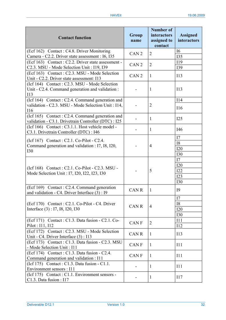
HAVEit 19.06.2009
Deliverable D12.1 Version 1.0 32
Contact function Group name
Number of interactors assigned to
contact
Assigned interactors
I6 (Ecf 162) Contact : C4.8. Driver Monitoring Camera - C2.2. Driver state assessment : I6, I35 CAN 2 2 I35
I19 (Ecf 163) Contact : C2.2. Driver state assessment - C2.3. MSU - Mode Selection Unit : I19, I39 CAN 2 2 I39 (Ecf 163) Contact : C2.3. MSU - Mode Selection Unit - C2.2. Driver state assessment: I13 CAN 2 1 I13
(Icf 164) Contact : C2.3. MSU - Mode Selection Unit - C2.4. Command generation and validation : I13
- 1 I13
I14 (Icf 164) Contact : C2.4. Command generation and validation - C2.3. MSU - Mode Selection Unit : I14, I16
- 2 I16
(Icf 165) Contact : C2.4. Command generation and validation - C3.1. Drivetrain Controller (DTC) : I25 - 1 I25
(Icf 166) Contact : C3.1.1. Host vehicle model - C3.1. Drivetrain Controller (DTC) : I46 - 1 I46
I7 I8 I20
(Icf 167) Contact : C2.1. Co-Pilot - C2.4. Command generation and validation : I7, I8, I20, I30
- 4
I30 I7 I20 I22 I23
(Icf 168) Contact : C2.1. Co-Pilot - C2.3. MSU - Mode Selection Unit : I7, I20, I22, I23, I30 - 5
I30 (Ecf 169) Contact : C2.4. Command generation and validation - C4. Driver Interface (3) : I9 CAN R 1 I9
I7 I8 I20
(Ecf 170) Contact : C2.1. Co-Pilot - C4. Driver Interface (3) : I7, I8, I20, I30 CAN R 4
I30 I11 (Ecf 171) Contact : C1.3. Data fusion - C2.1. Co-
Pilot : I11, I12 CAN F 2 I12 (Ecf 172) Contact : C2.3. MSU - Mode Selection Unit - C4. Driver Interface (3) : I13 CAN R 1 I13
(Ecf 173) Contact : C1.3. Data fusion - C2.3. MSU - Mode Selection Unit : I11 CAN F 1 I11
(Ecf 174) Contact : C1.3. Data fusion - C2.4. Command generation and validation : I11 CAN F 1 I11
(Icf 175) Contact : C1.3. Data fusion - C1.1. Environment sensors : I11 - 1 I11
(Icf 175) Contact : C1.1. Environment sensors - C1.3. Data fusion : I17 - 1 I17
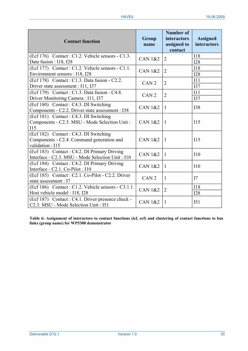
HAVEit 19.06.2009
Deliverable D12.1 Version 1.0 33
Contact function Group name
Number of interactors assigned to
contact
Assigned interactors
I18 (Ecf 176) Contact : C1.2. Vehicle sensors - C1.3. Data fusion : I18, I28 CAN 1&2 2 I28
I18 (Ecf 177) Contact : C1.2. Vehicle sensors - C1.1. Environment sensors : I18, I28 CAN 1&2 2 I28
I11 (Ecf 178) Contact : C1.3. Data fusion - C2.2. Driver state assessment : I11, I37 CAN 2 2 I37
I11 (Ecf 179) Contact : C1.3. Data fusion - C4.8. Driver Monitoring Camera : I11, I37 CAN 2 2 I37 (Ecf 180) Contact : C4.3. DI Switching Components - C2.2. Driver state assessment : I38 CAN 1&2 1 I38
(Ecf 181) Contact : C4.3. DI Switching Components - C2.3. MSU - Mode Selection Unit : I15
CAN 1&2 1 I15
(Ecf 182) Contact : C4.3. DI Switching Components - C2.4. Command generation and validation : I15
CAN 1&2 1 I15
(Ecf 183) Contact : C4.2. DI Primary Driving Interface - C2.3. MSU - Mode Selection Unit : I10 CAN 1&2 1 I10
(Ecf 184) Contact : C4.2. DI Primary Driving Interface - C2.1. Co-Pilot : I10 CAN 1&2 1 I10
(Ecf 185) Contact : C2.1. Co-Pilot - C2.2. Driver state assessment : I7 CAN 2 1 I7
I18 (Ecf 186) Contact : C1.2. Vehicle sensors - C3.1.1. Host vehicle model : I18, I28 CAN 1&2 2 I28 (Ecf 187) Contact : C4.1. Driver presence check - C2.3. MSU - Mode Selection Unit : I51 CAN 1&2 1 I51
Table 6: Assignment of interactors to contact functions (icf, ecf) and clustering of contact functions to bus links (group name) for WP5300 demonstrator
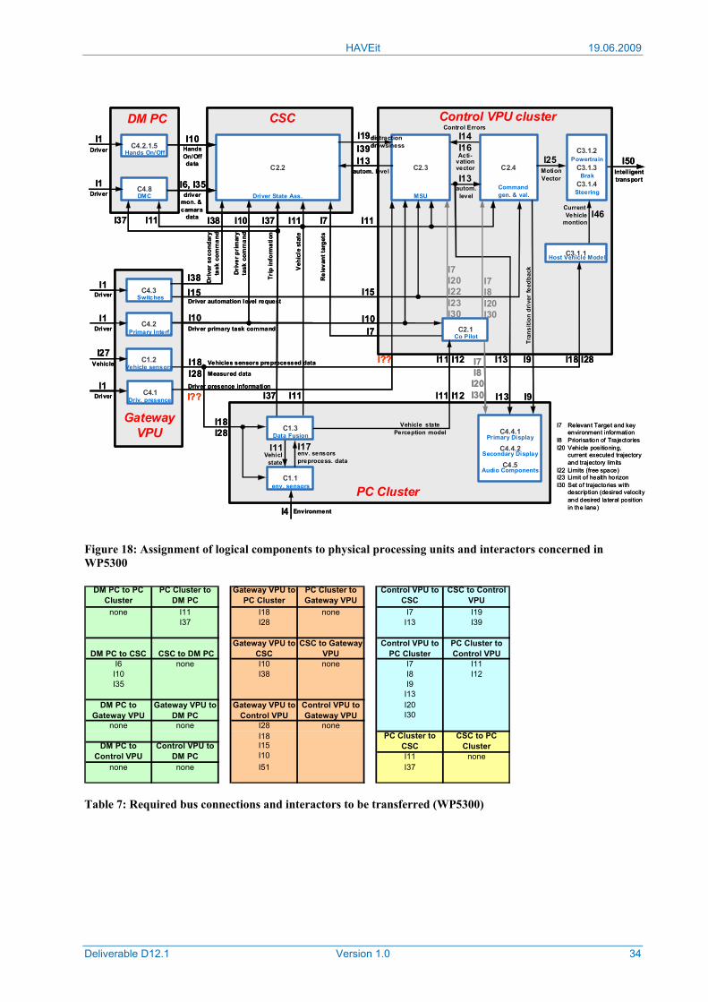
HAVEit 19.06.2009
Deliverable D12.1 Version 1.0 34
Figure 18: Assignment of logical components to physical processing units and interactors concerned in WP5300
DM PC to PC Cluster
PC Cluster to DM PC
Gateway VPU to PC Cluster
PC Cluster to Gateway VPU
Control VPU to CSC
CSC to Control VPU
none I11 I18 none I7 I19I37 I28 I13 I39
I6 none I10 none I7 I11I10 I38 I8 I12I35 I9
I13I20I30
none none I28 noneI18I15I10 I11 none
none none I51 I37
DM PC to Control VPU
Control VPU to DM PC
PC Cluster to CSC
CSC to PC Cluster
DM PC to Gateway VPU
Gateway VPU to DM PC
Control VPU to PC Cluster
PC Cluster to Control VPU
Gateway VPU to CSC
CSC to Gateway VPU
Gateway VPU to Control VPU
Control VPU to Gateway VPU
DM PC to CSC CSC to DM PC
Table 7: Required bus connections and interactors to be transferred (WP5300)
C3.1.2
C3.1.3
C3.1.4
C2.4
I46
I50
Control VPU cluster
I25
I11
C3.1.1
C2.3I13
I14 I16
C2.2
I39
CSC
I13
I19C4.2.1.5
I6, I35
I1
DM PC
C4.8I1
I10
C4.3
C1.2
GatewayVPU
I27
I1
C4.2
I38
I18I28
I18 I28
C4.1
I1
I38 I10
I10
Hands On/Off
DMC
Primary Interf.
Vehicle sensors
Switches
Driver State Ass. MSUCommandgen. & val.
Powertrain
Brak
Steering
Host Vehicle Model
Driver
Driver
Driver
Driver
Vehicle
Driv. presence
drivermon. & camara
data
HandsOn/Offdata
Dri
ver
seco
ndar
yta
sk c
omm
and
Dri
ver p
rim
ary
task
com
man
d
I15Driver automation level request
Vehicles sensors preprocessed data
Driver primary task command
Measured data
distractiondrowsiness
autom. level
Trip
info
rmat
ion
I37
C1.1
C1.3
I4
PC Cluster
C2.1
I17I11
C4.4.1
C4.4.2
C4.5
Data Fusion
env. sensors
Environment
I18I28
Vehiclstate
env. sensorspreprocess. data
Co Pilot
Primary Display
Secondary Display
Audio Components
MotionVector
Intelligenttransport
CurrentVehicle
montion
Veh
icle
sta
te
I11
autom.level
Vehicle statePerception model
I7
Rel
evan
t tar
gets
I11
I10
I11I37
Control Errors
Acti-vationvector
I13
Tran
sitio
n dr
iver
feed
back
I1Driver I??
Driver presence information
I??
I9
I7
I15
I7I8I20I30
I13 I9
I7I8I20I30
I7I20I22I23I30
I7 Relevant Target and key environment information
I8 Priorisation of TrajectoriesI20 Vehicle positioning,
current executed trajectoryand trajectory limits
I22 Limits (free space)I23 Limit of health horizonI30 Set of trajectories with
description (desired velocity and desired lateral position in the lane)
I11 I12
I11 I12I37
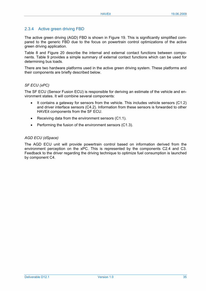
HAVEit 19.06.2009
Deliverable D12.1 Version 1.0 35
2.3.4 Active green driving FBD
The active green driving (AGD) FBD is shown in Figure 19. This is significantly simplified com-pared to the generic FBD due to the focus on powertrain control optimizations of the active green driving application.
Table 8 and Figure 20 describe the internal and external contact functions between compo-nents. Table 9 provides a simple summary of external contact functions which can be used for determining bus loads.
There are two hardware platforms used in the active green driving system. These platforms and their components are briefly described below.
SF ECU (xPC)
The SF ECU (Sensor Fusion ECU) is responsible for deriving an estimate of the vehicle and en-vironment states. It will combine several components:
• It contains a gateway for sensors from the vehicle. This includes vehicle sensors (C1.2) and driver interface sensors (C4.2). Information from these sensors is forwarded to other HAVEit components from the SF ECU.
• Receiving data from the environment sensors (C1.1).
• Performing the fusion of the environment sensors (C1.3).
AGD ECU (dSpace)
The AGD ECU unit will provide powertrain control based on information derived from the environment perception on the xPC. This is represented by the components C2.4 and C3. Feedback to the driver regarding the driving technique to optimize fuel consumption is launched by component C4.
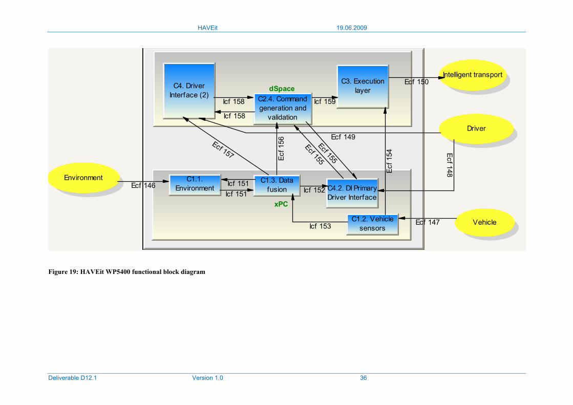
HAVEit 19.06.2009
Deliverable D12.1 Version 1.0 36
Environment
Vehicle
Driver
Intelligent transport
dSpace
xPC
C3. Executionlayer
C2.4. Commandgeneration and
validation
C4. DriverInterface (2)
C1.1.Environment
C1.2. Vehiclesensors
C1.3. Datafusion C4.2. DI Primary
Driver InterfaceEcf 146
Ecf 147
Ecf 148
Ecf 149
Ecf 150
Icf 151Icf 151
Icf 152
Icf 153
Ecf 1
54
Ecf 155Ecf 155Ec
f 156Ecf 157
Icf 158
Icf 158
Icf 159
Figure 19: HAVEit WP5400 functional block diagram
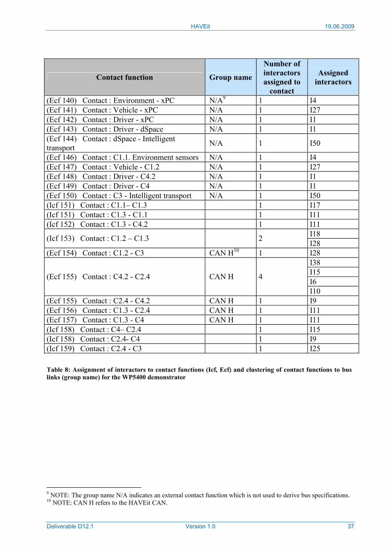
HAVEit 19.06.2009
Deliverable D12.1 Version 1.0 37
Contact function Group name
Number of interactors assigned to
contact
Assigned interactors
(Ecf 140) Contact : Environment - xPC N/A9 1 I4 (Ecf 141) Contact : Vehicle - xPC N/A 1 I27 (Ecf 142) Contact : Driver - xPC N/A 1 I1 (Ecf 143) Contact : Driver - dSpace N/A 1 I1 (Ecf 144) Contact : dSpace - Intelligent transport N/A 1 I50
(Ecf 146) Contact : C1.1. Environment sensors N/A 1 I4 (Ecf 147) Contact : Vehicle - C1.2 N/A 1 I27 (Ecf 148) Contact : Driver - C4.2 N/A 1 I1 (Ecf 149) Contact : Driver - C4 N/A 1 I1 (Ecf 150) Contact : C3 - Intelligent transport N/A 1 I50 (Icf 151) Contact : C1.1– C1.3 1 I17 (Icf 151) Contact : C1.3 - C1.1 1 I11 (Icf 152) Contact : C1.3 - C4.2 1 I11
I18 (Icf 153) Contact : C1.2 – C1.3 2 I28 (Ecf 154) Contact : C1.2 - C3 CAN H10 1 I28
I38 I15 I6 (Ecf 155) Contact : C4.2 - C2.4 CAN H 4
I10 (Ecf 155) Contact : C2.4 - C4.2 CAN H 1 I9 (Ecf 156) Contact : C1.3 - C2.4 CAN H 1 I11 (Ecf 157) Contact : C1.3 - C4 CAN H 1 I11 (Icf 158) Contact : C4– C2.4 1 I15 (Icf 158) Contact : C2.4- C4 1 I9 (Icf 159) Contact : C2.4 - C3 1 I25 Table 8: Assignment of interactors to contact functions (Icf, Ecf) and clustering of contact functions to bus links (group name) for the WP5400 demonstrator
9 NOTE: The group name N/A indicates an external contact function which is not used to derive bus specifications. 10 NOTE: CAN H refers to the HAVEit CAN.
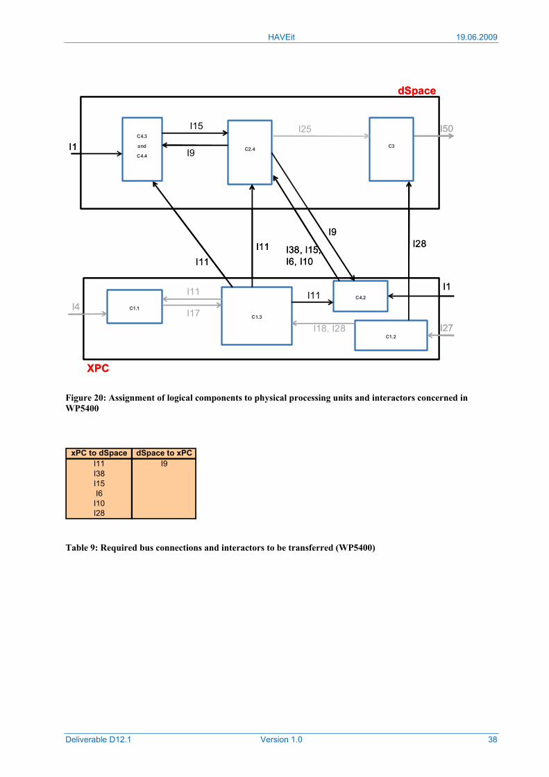
HAVEit 19.06.2009
Deliverable D12.1 Version 1.0 38
Figure 20: Assignment of logical components to physical processing units and interactors concerned in WP5400
xPC to dSpace dSpace to xPC
I11 I9I38I15I6I10I28
Table 9: Required bus connections and interactors to be transferred (WP5400)
C1.1
C1.2
C1.3
C2.4
I4
I27I17
I18, I28
I11
I1
I50
dSpace
XPC
I1I11C4.2
C4.3
and
C4.4
C3
I11
I11 I28I38, I15, I6, I10
I9
I25I15
I9
C1.1
C1.2
C1.3
C2.4
I4
I27I17
I18, I28
I11
I1
I50
dSpace
XPC
I1I11C4.2
C4.3
and
C4.4
C3
I11
I11 I28I38, I15, I6, I10
I9
I25I15
I9
HAVEit 19.06.2009
Deliverable D12.1 Version 1.0 39
3 Interactor definition In the previous section describing the first steps towards the definition of the system architec-ture, functional blocks have been defined and interconnected via the so-called "interactors". In-teractors describe a kind of information flow with their name giving a hint about the quality of information and their source and destinations giving the logical path of the information.
In the FBD the interactors have been mapped to contact functions. Contact functions have then been grouped to certain bus connections, e.g. CAN1, CAN2. In order to select the appropriate bus technology it is necessary to know the amount of information to be exchanged, therefore the interactors have to be specified in detail. This detailed specification is given in the next sec-tions.
The focus of the interactor description lies on a preparation for the bus transmission, so the digital resolution was chosen carefully to save bandwidth. If a certain interactor in a concrete SP4000 or SP5000 demonstrator does not have to be transmitted (ECU internal information, for example), this resolution restriction may be disregarded.
Every interactor is to be regarded as a group of signals sharing the same information path. These signals are divided into sub-signals, sub-sub-signals and so on.
The content of the interactors is described in an Excel based document which is available for the project members only.
HAVEit 19.06.2009
Deliverable D12.1 Version 1.0 40
4 Further architecture investigations Based on the existing architectural decisions and the results described in the sections 2 and 3 of this document, further architecture investigations are mandatory.
Those further investigations are executed model based with the following targets:
• formal system wide check of interfaces
• formal consistency check of whole models on system scope
• possibility to simulate the functionalities
• link to further tools by XML transformation, like the AUTOSAR tool for RTE (Run Time Environment) generation (MOSART11)
• automated documentation generation based on the model
The possibility to simulate the functionalities also provides the opportunity to perform a model based safety analysis, if the error behavior is modeled.
Further architecture analysis is planned to be done in cooperation with the project ATESST2, see www.atesst.org. It is intended to report the results of this common analysis in the deliverable D43.1 in project month 33 (D43.1 explains the implemented architecture of the WP4300 demonstrator that will be based on the generic HAVEit architecture described above).
For the HAVEit project, in addition to the generic architecture, a further architectural issue is of particular concern: The safety relevant architecture in the drivetrain sub-systems for drive-by-wire applications (steer-by-wire in WP4100 and brake-by-wire in WP4200). Chapter 5 is dedica-ted to this topic.
11 MOSART: Modeling autOSAR Tool
HAVEit 19.06.2009
Deliverable D12.1 Version 1.0 41
5 X-by-Wire: Architectural considerations X-by-wire applications have come a long way in the aircraft industry, with the first full fly-by-wire control system in a serial production plane available as early as 1952 in the Avro Vulcan. The first fly-by-wire equipped commercial airliner, the Airbus A320, took off for its maiden flight in 1987. In the automotive domain, however, only parts of the main control elements have seen the application of x-by-wire on a large scale, namely the electronic throttle pedal which nowa-days is standard in all modern vehicles.
Brake systems which could technically be classified as “brake-by-wire” were introduced by Daimler and Toyota a couple of years ago, but these systems still used the classic hydraulic wheel brakes whereby the pressure is supplied by an electric pump rather than by a master cylinder connected to the brake pedal. Therefore they cannot fully realize one of the main advantages of brake-by-wire systems: the optimal controllability of each wheel's individual brake power in order to operate as close as possible to the friction curve maximum in an emergency brake situation. In the HAVEit approach, the hydraulic system will be replaced by mechatronical actuators, the electronic wedge brake that permits to reach a level of control over each wheel brake that would not be possible with hydraulic brake cylinders. The advantages of such systems are numerous and include dramatic improvements in modern safety systems such as ABS and ESP as well as economic and ecologic aspects in the production and recycling of vehicles.
Steer-by-wire systems have not yet found their way into the market of passenger vehicles, both for technical and legal reasons. While the applications in the aircraft domain have proven that it is technically feasible to design by-wire-systems which are at least as safe as mechanically coupled systems, the complexity and maintenance effort of these systems is too high to bring them forward in the automotive branch without modifications. However, in the last years a couple of systems have been brought to series production in passenger vehicles that clearly pave the way towards steer-by-wire. One of the most prominent examples is the electrically assisted power steering, which today is already widely used in smaller passenger vehicle segments, thus replacing the hydraulic steering aid which has been the standard for over 50 years. Electric power steering usually consists of a torque sensor in the steering column measuring the driver’s effort, and an electric actuator which then supplies the appropriate steering support. Again, the greater control over the steering actuator allows for some additional features that are not feasible in classic power steering. VW, for example, offers an assistance system that can fully take over the steering task while parking a vehicle in parallel, using the electric power steering as actuator. The electric power steering is not only a step towards true steer-by-wire systems on the functional level, but also in terms of integrating safety critical mechatronical systems into passenger vehicles. While a total failure of the system still leaves a vehicle controllable (with a higher steering effort, just as a classic servo steering), uncontrollable movements of the actuator could lead to highly severe consequences and must therefore be safely avoided by the design.
Another relatively new steering system is the BMW Active Steering which introduces a planetary gear in the steering column. The planetary gear has two inputs, the steering wheel shaft and an electromotor as well as one output connected to the steering pinion at the front axle. The output movement of the planetary gear is determined by adding the steering wheel and the electro-motor rotation. When the electromotor is not operating, the planetary gear just passes through the rotation of the steering wheel; therefore the system also has an inherent fail silent behavior. On the functional level, the active steering can – at least theoretically – totally separate the movement of the steering wheel from the movement of the front axle steering, thus providing full steer-by-wire functionalities. This is of course limited by the dynamics of the steering aid and the active steering actuators. BMW uses the system to provide a speed dependent steering ratio with a more direct steering at low speeds. It is also integrated in the ESP (or DSC, for that matter).

HAVEit 19.06.2009
Deliverable D12.1 Version 1.0 42
The HAVEit approach towards steer-by-wire is designed to go one step beyond systems that are currently available on the market while trying to keep the additional costs and safety issues on a reasonable level. Therefore, the fundamental design decision was to construct a true steer-by-wire system with a mechanical backup layer which only gets active in the case of a severe system failure. A special focus was put on highly automated driving modes, which are an important part of the HAVEit endeavor: A steer-by-wire system with a mechanic backup nor-mally switches off all actuators immediately if a failure occurs and therefore falls back to a non-assisted mechanic steering system. However, such a behavior is not acceptable for a system that can operate in automated driving modes, as in this case the driver might not always be prepared to regain control over the vehicle immediately. The HAVEit steer-by-wire system has therefore another redundancy layer which allows keeping the vehicle under control for a certain amount of time, even when the main steering actuator fails.
5.1 Steer- and Brake-by-wire architecture
5.1.1 Steer-by-wire architecture
The basic configuration of the HAVEit steer-by-wire system was derived from requirements resulting from the planned highly automated driving applications. Since the haptic communi-cation between the driver and the automation system is a very important target of HAVEit, a complete dynamic separation of steering wheel and steering pinion at the front axle was desired. A mechanical backup-layer was introduced, because in this case, the actuators can be designed to be fail-silent rather than fail-safe while still preserving the required level of safety. Since existing electrical steering systems also require fail-silent actuators, the HAVEit steering-system can resort to those components and therefore significantly reduce the development effort and make a serial production of the system much more feasible.
It should be noted that the system to be implemented in HAVEit is a functional prototype. This means that not all safety requirements for a steer-by-wire system for the use on public roads might be matched, especially due to cost restrictions concerning the development of specialized actuators. The main focus was put on the feasibility of serial production, including production costs, and the functionality of the system in order to be able to implement fully functioning prototypes of the highly automated systems to be developed in the course of the project.
Mechanical configuration
The basic mechanical configuration of the steering-system is shown in Figure 21. Between steering wheel and the steering pinion an electromagnetic clutch is installed in the steering column. For safety reasons the clutch is kept open by an electromagnet, thus coupling automatically through a spring or permanent magnet when the electric power is shut off. Even in the unlikely case of a total power failure, the vehicle still stays controllable.
During the normal operation of the steer-by-wire system, the clutch is open and there is no mechanical connection between the steering wheel and the front axle. The feedback torque at the steering wheel is generated by the driver feedback actuator, while the steering task is performed by the steering actuator. In the WP4100 steer-by-wire vehicle, the steering actuator will consist of the electric servo steering motor which is standard in the VW Passat. A software modification of the servo steering ECU allows to command the steering action via the CAN bus.
One particular requirement for the HAVEit steering system is the ability to operate safely during highly or fully automated driving. As pointed out at the beginning of chapter 5, a safety concept that would switch the steering system immediately back to manual, non-assisted driving upon
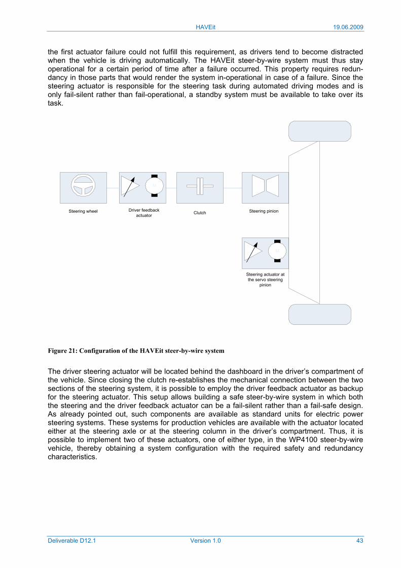
HAVEit 19.06.2009
Deliverable D12.1 Version 1.0 43
the first actuator failure could not fulfill this requirement, as drivers tend to become distracted when the vehicle is driving automatically. The HAVEit steer-by-wire system must thus stay operational for a certain period of time after a failure occurred. This property requires redun-dancy in those parts that would render the system in-operational in case of a failure. Since the steering actuator is responsible for the steering task during automated driving modes and is only fail-silent rather than fail-operational, a standby system must be available to take over its task.
Figure 21: Configuration of the HAVEit steer-by-wire system
The driver steering actuator will be located behind the dashboard in the driver’s compartment of the vehicle. Since closing the clutch re-establishes the mechanical connection between the two sections of the steering system, it is possible to employ the driver feedback actuator as backup for the steering actuator. This setup allows building a safe steer-by-wire system in which both the steering and the driver feedback actuator can be a fail-silent rather than a fail-safe design. As already pointed out, such components are available as standard units for electric power steering systems. These systems for production vehicles are available with the actuator located either at the steering axle or at the steering column in the driver’s compartment. Thus, it is possible to implement two of these actuators, one of either type, in the WP4100 steer-by-wire vehicle, thereby obtaining a system configuration with the required safety and redundancy characteristics.
Smart-Aktuator
M
Lenkrad Kupplung Getriebe
Smart-Aktuator
M
Steering actuator at the servo steering
pinion
Driver feedback actuator
Steering pinionClutchSteering wheel
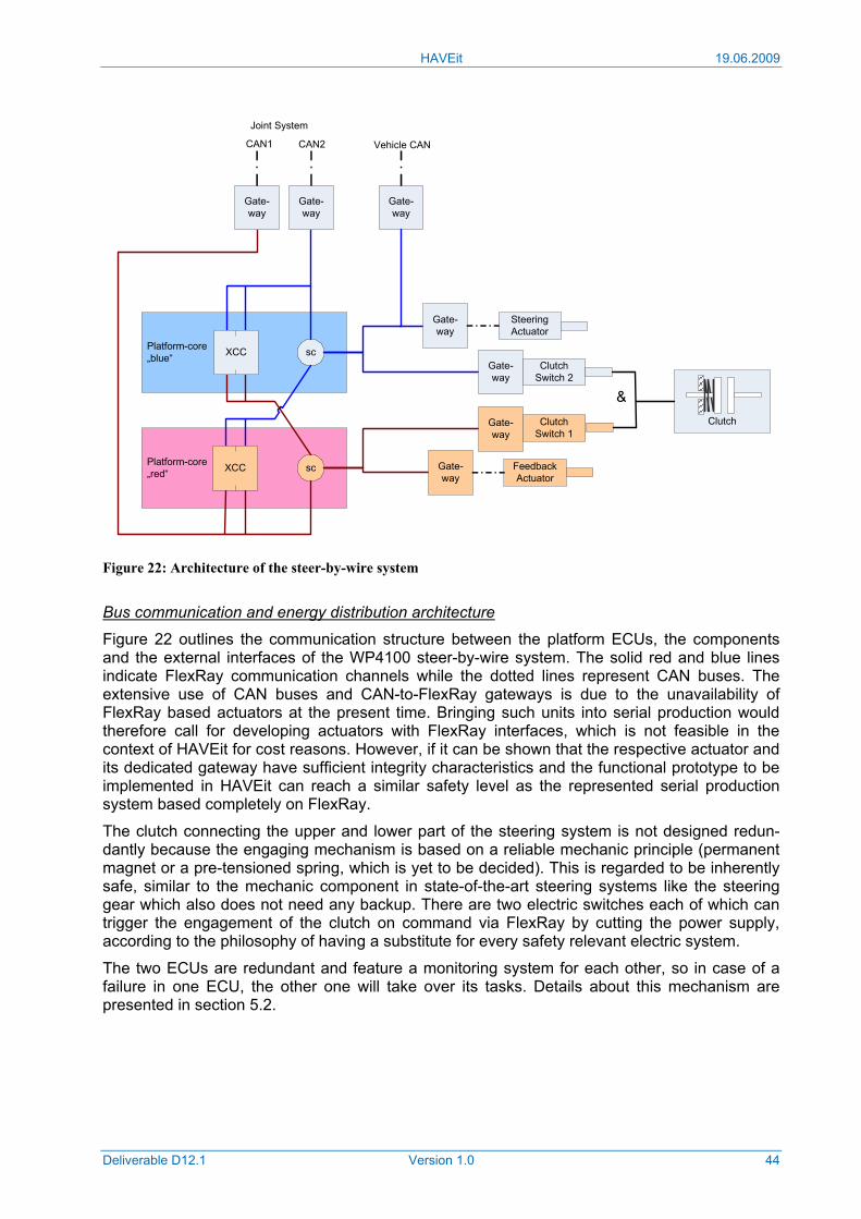
HAVEit 19.06.2009
Deliverable D12.1 Version 1.0 44
Figure 22: Architecture of the steer-by-wire system
Bus communication and energy distribution architecture
Figure 22 outlines the communication structure between the platform ECUs, the components and the external interfaces of the WP4100 steer-by-wire system. The solid red and blue lines indicate FlexRay communication channels while the dotted lines represent CAN buses. The extensive use of CAN buses and CAN-to-FlexRay gateways is due to the unavailability of FlexRay based actuators at the present time. Bringing such units into serial production would therefore call for developing actuators with FlexRay interfaces, which is not feasible in the context of HAVEit for cost reasons. However, if it can be shown that the respective actuator and its dedicated gateway have sufficient integrity characteristics and the functional prototype to be implemented in HAVEit can reach a similar safety level as the represented serial production system based completely on FlexRay.
The clutch connecting the upper and lower part of the steering system is not designed redun-dantly because the engaging mechanism is based on a reliable mechanic principle (permanent magnet or a pre-tensioned spring, which is yet to be decided). This is regarded to be inherently safe, similar to the mechanic component in state-of-the-art steering systems like the steering gear which also does not need any backup. There are two electric switches each of which can trigger the engagement of the clutch on command via FlexRay by cutting the power supply, according to the philosophy of having a substitute for every safety relevant electric system.
The two ECUs are redundant and feature a monitoring system for each other, so in case of a failure in one ECU, the other one will take over its tasks. Details about this mechanism are presented in section 5.2.
Clutch
Platform-core„red“
Platform-core„blue“
Feedback Actuator
Steering Actuator
sc
sc
Gate-way
Gate-way
Clutch Switch 1
Clutch Switch 2
XCC
XCC
Gate-way
Gate-way
Gate-way
&
CAN1 CAN2
Gate-way
Joint System
Vehicle CAN
Gate-way
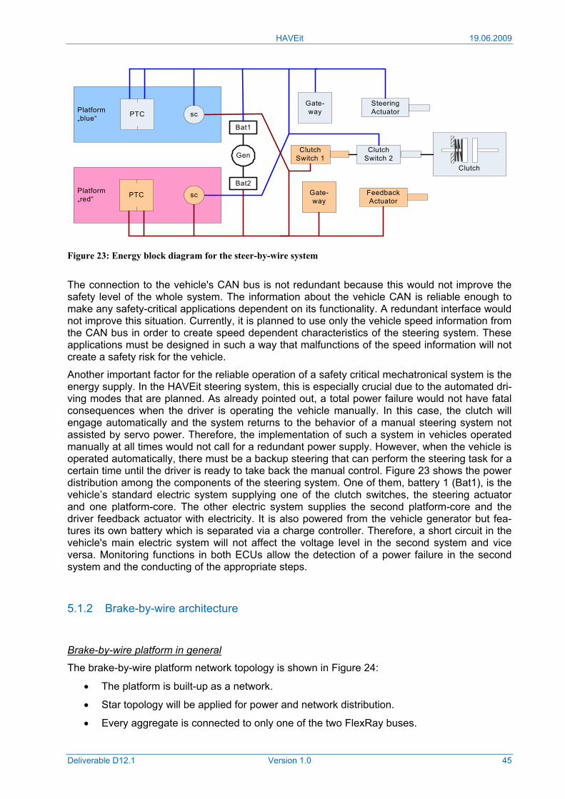
HAVEit 19.06.2009
Deliverable D12.1 Version 1.0 45
Figure 23: Energy block diagram for the steer-by-wire system
The connection to the vehicle's CAN bus is not redundant because this would not improve the safety level of the whole system. The information about the vehicle CAN is reliable enough to make any safety-critical applications dependent on its functionality. A redundant interface would not improve this situation. Currently, it is planned to use only the vehicle speed information from the CAN bus in order to create speed dependent characteristics of the steering system. These applications must be designed in such a way that malfunctions of the speed information will not create a safety risk for the vehicle.
Another important factor for the reliable operation of a safety critical mechatronical system is the energy supply. In the HAVEit steering system, this is especially crucial due to the automated dri-ving modes that are planned. As already pointed out, a total power failure would not have fatal consequences when the driver is operating the vehicle manually. In this case, the clutch will engage automatically and the system returns to the behavior of a manual steering system not assisted by servo power. Therefore, the implementation of such a system in vehicles operated manually at all times would not call for a redundant power supply. However, when the vehicle is operated automatically, there must be a backup steering that can perform the steering task for a certain time until the driver is ready to take back the manual control. Figure 23 shows the power distribution among the components of the steering system. One of them, battery 1 (Bat1), is the vehicle’s standard electric system supplying one of the clutch switches, the steering actuator and one platform-core. The other electric system supplies the second platform-core and the driver feedback actuator with electricity. It is also powered from the vehicle generator but fea-tures its own battery which is separated via a charge controller. Therefore, a short circuit in the vehicle's main electric system will not affect the voltage level in the second system and vice versa. Monitoring functions in both ECUs allow the detection of a power failure in the second system and the conducting of the appropriate steps.
5.1.2 Brake-by-wire architecture
Brake-by-wire platform in general
The brake-by-wire platform network topology is shown in Figure 24:
• The platform is built-up as a network.
• Star topology will be applied for power and network distribution.
• Every aggregate is connected to only one of the two FlexRay buses.
Platform„red“
Platform„blue“ sc
scPTC
PTC
Gen
Bat1
Bat2
Clutch
Feedback Actuator
Steering Actuator
Gate-way
Gate-way
Clutch Switch 1
Clutch Switch 2
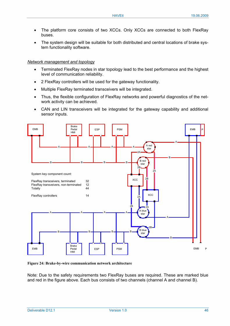
HAVEit 19.06.2009
Deliverable D12.1 Version 1.0 46
• The platform core consists of two XCCs. Only XCCs are connected to both FlexRay buses.
• The system design will be suitable for both distributed and central locations of brake sys-tem functionality software.
Network management and topology
• Terminated FlexRay nodes in star topology lead to the best performance and the highest level of communication reliability.
• 2 FlexRay controllers will be used for the gateway functionality.
• Multiple FlexRay terminated transceivers will be integrated.
• Thus, the flexible configuration of FlexRay networks and powerful diagnostics of the net-work activity can be achieved.
• CAN and LIN transceivers will be integrated for the gateway capability and additional sensor inputs.
Figure 24: Brake-by-wire communication network architecture
Note: Due to the safety requirements two FlexRay buses are required. These are marked blue and red in the figure above. Each bus consists of two channels (channel A and channel B).
System key component count:
FlexRay transceivers, terminated 32FlexRay transveivers, non-terminated 12Totally 44
FlexRay controllers 14
2A
2A
2B
2A
2B
2B
2B
EMB ESP EMB P
EMB PEMB ESP PSMBrakePedal HMI
BrakePedal HMI
PSM
XCC
XCC
A redstar
B redstar
A bluestar
B bluestar
2A
A A A A
A
A A A A
A
B
B B B B
B
B B B B
System key component count:
FlexRay transceivers, terminated 32FlexRay transveivers, non-terminated 12Totally 44
FlexRay controllers 14
2A
2A2A
2B
2A2A
2B2B
2B2B
2B2B
EMB ESP EMB PEMB P
EMB PEMB PEMB ESP PSMBrakePedal HMI
EMB ESP PSMBrakePedal HMI
BrakePedal HMI
PSM
XCC
XCC
A redstar
B redstar
A bluestar
B bluestar
2A2A
AA AA AA AA
AA
AA AA AA AA
AA
BB
BB BB BB BB
BB
BB BB BB BB
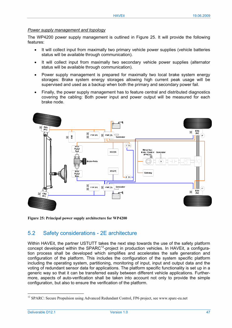
HAVEit 19.06.2009
Deliverable D12.1 Version 1.0 47
Power supply management and topology
The WP4200 power supply management is outlined in Figure 25. It will provide the following features:
• It will collect input from maximally two primary vehicle power supplies (vehicle batteries status will be available through communication).
• It will collect input from maximally two secondary vehicle power supplies (alternator status will be available through communication).
• Power supply management is prepared for maximally two local brake system energy storages: Brake system energy storages allowing high current peak usage will be supervised and used as a backup when both the primary and secondary power fail.
• Finally, the power supply management has to feature central and distributed diagnostics covering the cabling: Both power input and power output will be measured for each brake node.
Figure 25: Principal power supply architecture for WP4200
5.2 Safety considerations - 2E architecture
Within HAVEit, the partner USTUTT takes the next step towards the use of the safety platform concept developed within the SPARC12-project in production vehicles. In HAVEit, a configura-tion process shall be developed which simplifies and accelerates the safe generation and configuration of the platform. This includes the configuration of the system specific platform including the operating system, partitioning, monitoring of input, input and output data and the voting of redundant sensor data for applications. The platform specific functionality is set up in a generic way so that it can be transferred easily between different vehicle applications. Further-more, aspects of auto-verification shall be taken into account not only to provide the simple configuration, but also to ensure the verification of the platform.
12 SPARC: Secure Propulsion using Advanced Redundant Control, FP6 project, see www.sparc-eu.net
HAVEit 19.06.2009
Deliverable D12.1 Version 1.0 48
5.2.1 Safety
Safety critical systems in today’s vehicles are always realized with at least one mechanical backup. As a consequence, the probability for losing the functionality of such systems during the vehicle operation is in the order of magnitude of 10-8 per hour, while the corresponding probability for simplex systems (1E-architecture) without mechanical backup lies in the order of magnitude of about 10-4 per hour according to experience. One aim of HAVEit is to provide a safety critical 2E system architecture (which means an electrical system with electrical backup) without mechanical backup, which still ensures a quantified safety in the order of magnitude of 10-8 per hour; (it has to be defined within the project whether a quantified safety shall be achieved, which is derived from statistical data about how often a loss of the brake system takes place and therefore will be accepted in today’s vehicles, or whether the safety shall be derived by applying SIL3 or even SIL4 with respect to IEC61508). In [3] it has been shown for a dedicated mission scenario that the demanded level of safety can be basically achieved by applying redundancy to ensure a fail-operational behavior.
As already shown in SPARC, a platform concept is an adequate approach to provide the requi-red redundancy in an efficient way. Besides advantages like
• cost-reduction during vehicle manufacturing (since all vehicles, even different vehicle types, only have to be equipped with one and the same unit, namely the platform; this will be achieved, since the platform core as well as the smart aggregates will be transferable)
• easy functional extension (by adding new XCCs in combination with the fact that within one XCC applications can be executed with totally different levels of safety) and
• advanced vehicle functions can be developed (since in the platform generally each func-tion can access the information provided by all sensors and actuators),
the main features of the platform approach are
• the optimisation of the applied degree of redundancy (since the platform is designed to provide easy expansion (scalability), redundancy can easily be adapted to the individual requirements) and
• separation of functionality and safety (while the vehicle functionality is implemented on the platform via applications, the redundancy management takes care of the required safety).
The evolution of the platform concept towards its use in production vehicles takes place as follows:
• The development of a safe configuration process shall simplify and secure the genera-tion of the safety providing redundancy management.
• By evaluating the aspects of a potential auto-verification, a first step towards a fast, auto-mated verification and homologation of the system functions, which are implemented in the platform core, shall be achieved.
• For the first time a system function (brake-by-wire) implemented in the platform core shall be pre-homologated by national authorities.
• The safety level of today’s safety systems with cost-consuming mechanical backups shall be achieved and even be beaten.
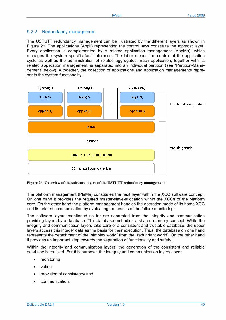
HAVEit 19.06.2009
Deliverable D12.1 Version 1.0 49
5.2.2 Redundancy management
The USTUTT redundancy management can be illustrated by the different layers as shown in Figure 26. The applications (Appli) representing the control laws constitute the topmost layer. Every application is complemented by a related application management (AppMa), which manages the system specific fault tolerance. The latter means the control of the application cycle as well as the administration of related aggregates. Each application, together with its related application management, is separated into an individual partition (see “Partition-Mana-gement” below). Altogether, the collection of applications and application managements repre-sents the system functionality.
Figure 26: Overview of the software-layers of the USTUTT redundancy management
The platform management (PlaMa) constitutes the next layer within the XCC software concept. On one hand it provides the required master-slave-allocation within the XCCs of the platform core. On the other hand the platform management handles the operation mode of its home XCC and its related communication by evaluating the results of the failure monitoring.
The software layers mentioned so far are separated from the integrity and communication providing layers by a database. This database embodies a shared memory concept. While the integrity and communication layers take care of a consistent and trustable database, the upper layers access this integer data as the basis for their execution. Thus, the database on one hand represents the detachment of the “simplex world” from the “redundant world”. On the other hand it provides an important step towards the separation of functionality and safety.
Within the integrity and communication layers, the generation of the consistent and reliable database is realized. For this purpose, the integrity and communication layers cover
• monitoring
• voting
• provision of consistency and
• communication.
HAVEit 19.06.2009
Deliverable D12.1 Version 1.0 50
Monitoring means the detection of failures concerning input data from aggregates of already sent data of the XCC (wrap) and XCC internal data (x-lane-monitoring). Voting means the evaluation of trustable input values. Consistency needs to be provided for the XCC-internal database, but also for the central platform core internal database (inter-XCC). Furthermore, the consistency of the output data needs to be ensured. Communication in the upper listing stands for the reading and writing of FlexRay messages.
The bottom layer covers the operating system including synchronization, scheduling and the drivers. Furthermore, this layer provides the already mentioned partitioning. The latter plays an important role in ensuring safety; therefore it is worth taking a closer look at it. In a platform concept, by definition, a number of independent functionalities are merged in one XCC. So, it has to be ensured that these functionalities do not affect each other, especially in the presence of faults. Moreover, it would be comfortable, if each function could be integrated, executed and (in the future) be homologized independently from all other functions. To achieve this goal, a partitioning will be implemented, which separates the applications (and the related application management) from each other in a way, that
• a private memory area is reserved for each partition (within the partitioning it is ensured that the application or application management in one partition does not get access to the ROM or RAM area of another partition) and
• a private time interval is reserved for each partition (after exceeding the dedicated time limit, the execution within the partition will be interrupted and the start of the next dedicated partition will be initiated. In consequence, a design error like an infinite loop within one application will not disturb the execution of any other function).
Configuration process
The configuration of the previously introduced software layers will be done as follows:
• Application layer: Applications need to be developed and adapted to each vehicle type independently. Since these will be delivered as complete and compiled software (by the vehicle owners, i.e. the partners DLR for steer-by-wire and HLX for brake-by-wire), the applications shall be not part of the configuration process.
• Application management layer: The application management needs to be developed considering the individual conditions of each application as well as the framework of the USTUTT redundancy management. Therefore, modelling the application management seems to be a suitable solution within the configuration process and shall be further assessed.
• Platform management layer: Since the platform management is only dependent on the platform core, it can generally be developed just once for all vehicle configurations. Within the scope of the configuration process, the generation of the platform manage-ment by modelling shall be used.
• Database, integrity, communication and operating system layers: The software modules in these layers need to be developed regarding the individual applications as well as the vehicle specific applications and data flow. For the configuration process, it shall be assessed how they can be generated by applying model based configurability. The software framework (partitioning, scheduling, IO-handling, data routing, monitoring / voting) shall be developed just once. The system / vehicle specific adaptation shall be achieved via configuration tables that will be generated from a vehicle specific model based tool framework.
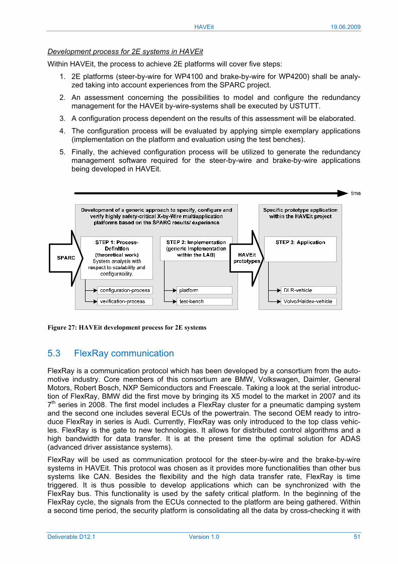
HAVEit 19.06.2009
Deliverable D12.1 Version 1.0 51
Development process for 2E systems in HAVEit
Within HAVEit, the process to achieve 2E platforms will cover five steps:
1. 2E platforms (steer-by-wire for WP4100 and brake-by-wire for WP4200) shall be analy-zed taking into account experiences from the SPARC project.
2. An assessment concerning the possibilities to model and configure the redundancy management for the HAVEit by-wire-systems shall be executed by USTUTT.
3. A configuration process dependent on the results of this assessment will be elaborated.
4. The configuration process will be evaluated by applying simple exemplary applications (implementation on the platform and evaluation using the test benches).
5. Finally, the achieved configuration process will be utilized to generate the redundancy management software required for the steer-by-wire and brake-by-wire applications being developed in HAVEit.
Figure 27: HAVEit development process for 2E systems
5.3 FlexRay communication
FlexRay is a communication protocol which has been developed by a consortium from the auto-motive industry. Core members of this consortium are BMW, Volkswagen, Daimler, General Motors, Robert Bosch, NXP Semiconductors and Freescale. Taking a look at the serial introduc-tion of FlexRay, BMW did the first move by bringing its X5 model to the market in 2007 and its 7th series in 2008. The first model includes a FlexRay cluster for a pneumatic damping system and the second one includes several ECUs of the powertrain. The second OEM ready to intro-duce FlexRay in series is Audi. Currently, FlexRay was only introduced to the top class vehic-les. FlexRay is the gate to new technologies. It allows for distributed control algorithms and a high bandwidth for data transfer. It is at the present time the optimal solution for ADAS (advanced driver assistance systems).
FlexRay will be used as communication protocol for the steer-by-wire and the brake-by-wire systems in HAVEit. This protocol was chosen as it provides more functionalities than other bus systems like CAN. Besides the flexibility and the high data transfer rate, FlexRay is time triggered. It is thus possible to develop applications which can be synchronized with the FlexRay bus. This functionality is used by the safety critical platform. In the beginning of the FlexRay cycle, the signals from the ECUs connected to the platform are being gathered. Within a second time period, the security platform is consolidating all the data by cross-checking it with
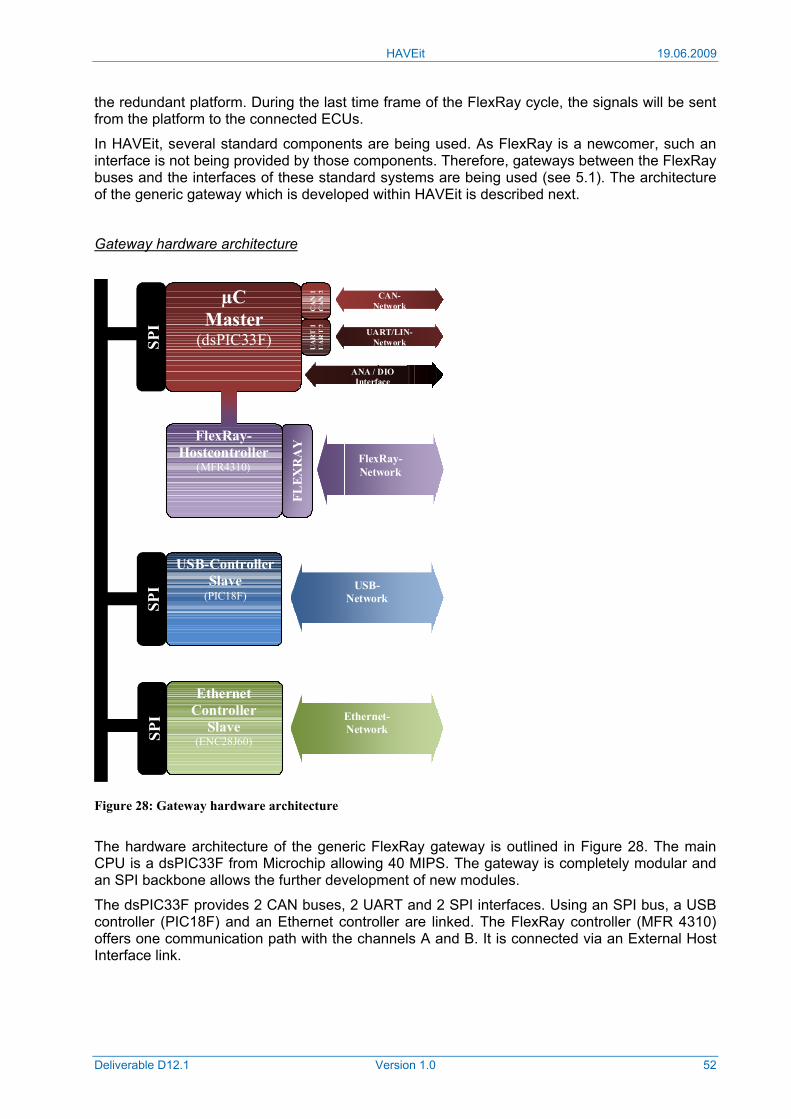
HAVEit 19.06.2009
Deliverable D12.1 Version 1.0 52
the redundant platform. During the last time frame of the FlexRay cycle, the signals will be sent from the platform to the connected ECUs.
In HAVEit, several standard components are being used. As FlexRay is a newcomer, such an interface is not being provided by those components. Therefore, gateways between the FlexRay buses and the interfaces of these standard systems are being used (see 5.1). The architecture of the generic gateway which is developed within HAVEit is described next.
Gateway hardware architecture
Figure 28: Gateway hardware architecture
The hardware architecture of the generic FlexRay gateway is outlined in Figure 28. The main CPU is a dsPIC33F from Microchip allowing 40 MIPS. The gateway is completely modular and an SPI backbone allows the further development of new modules.
The dsPIC33F provides 2 CAN buses, 2 UART and 2 SPI interfaces. Using an SPI bus, a USB controller (PIC18F) and an Ethernet controller are linked. The FlexRay controller (MFR 4310) offers one communication path with the channels A and B. It is connected via an External Host Interface link.
µC Master
(dsPIC33F) SPI
CA
N 1
C
AN
2U
AR
T 1
UA
RT
2
USB-Controller Slave
(PIC18F)
SPI
SPI
Ethernet Controller
Slave (ENC28J60)
FLEX
RA
Y FlexRay-
Hostcontroller (MFR4310)
FlexRay-Network
USB-Network
Ethernet-Network
UART/LIN-Network
CAN- Network
ANA / DIO Interface
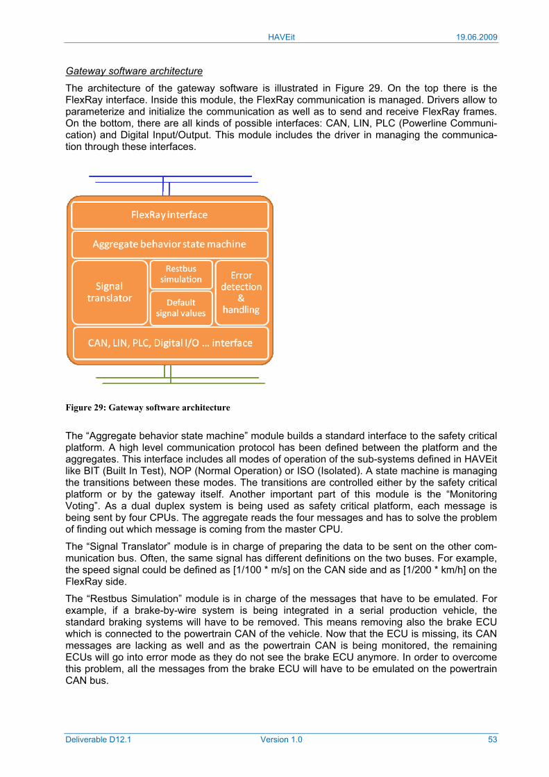
HAVEit 19.06.2009
Deliverable D12.1 Version 1.0 53
Gateway software architecture
The architecture of the gateway software is illustrated in Figure 29. On the top there is the FlexRay interface. Inside this module, the FlexRay communication is managed. Drivers allow to parameterize and initialize the communication as well as to send and receive FlexRay frames. On the bottom, there are all kinds of possible interfaces: CAN, LIN, PLC (Powerline Communi-cation) and Digital Input/Output. This module includes the driver in managing the communica-tion through these interfaces.
Figure 29: Gateway software architecture
The “Aggregate behavior state machine” module builds a standard interface to the safety critical platform. A high level communication protocol has been defined between the platform and the aggregates. This interface includes all modes of operation of the sub-systems defined in HAVEit like BIT (Built In Test), NOP (Normal Operation) or ISO (Isolated). A state machine is managing the transitions between these modes. The transitions are controlled either by the safety critical platform or by the gateway itself. Another important part of this module is the “Monitoring Voting”. As a dual duplex system is being used as safety critical platform, each message is being sent by four CPUs. The aggregate reads the four messages and has to solve the problem of finding out which message is coming from the master CPU.
The “Signal Translator” module is in charge of preparing the data to be sent on the other com-munication bus. Often, the same signal has different definitions on the two buses. For example, the speed signal could be defined as [1/100 * m/s] on the CAN side and as [1/200 * km/h] on the FlexRay side.
The “Restbus Simulation” module is in charge of the messages that have to be emulated. For example, if a brake-by-wire system is being integrated in a serial production vehicle, the standard braking systems will have to be removed. This means removing also the brake ECU which is connected to the powertrain CAN of the vehicle. Now that the ECU is missing, its CAN messages are lacking as well and as the powertrain CAN is being monitored, the remaining ECUs will go into error mode as they do not see the brake ECU anymore. In order to overcome this problem, all the messages from the brake ECU will have to be emulated on the powertrain CAN bus.

HAVEit 19.06.2009
Deliverable D12.1 Version 1.0 54
The “Default Signal Value” module initializes the values of the signals to default when booting up the gateway or when losing one of the two communication interfaces.
Finally, the “Error detection and handling” module monitors the connected aggregates and the gateway itself. In case of a failure it will react accordingly in order to notify the safety critical plat-form about the status and the availability of the sub-system.
HAVEit 19.06.2009
Deliverable D12.1 Version 1.0 55
6 Conclusions A common functional view on the HAVEit highly automated vehicle applications has been defined. On the top level, the SADT representation of this functional view is structured in four different layers: Perception layer, command layer, execution layer and a layer to integrate the driver in the automation loop. On the basis of this common SADT representation, the hardware oriented generic functional block diagram (FBD) has been defined. From the generic FBD the demonstrator specific FDBs have been derived to ensure a commonly agreed information flow on the one hand and to integrate vehicle specific extensions on the other hand.
To be able to effectively cooperate within the consortium and to exchange information between components developed by several partners, significant effort has been spent on defining the information flow (defined as precise as possible by the so-called interactors, i.e. down to parameters, data representation and update rate). It is important to notice that the currently available interactor definition is an excellent starting point, but experiences from earlier projects show the need for adaptations throughout the implementation and integration phases of the project. To ensure that all partners will always be able to work with the most recent definition of the interactors, this information shall be maintained until the end of the project using the TDC database. This deliverable presents the current state of the interactor definition as a starting point, the final definition will be part of the final project documentation.
The different layers in the overall HAVEit architecture call for different safety requirements. While for the top level, e.g. the driver can intervene and thus the safety requirements are quite low, for the lower levels, e.g. the execution layer, driver reaction is too slow to intervene, thus safety requirements increase a lot. Obviously, the highest safety requirements result for the steer- and brake-by-wire actuators of the drivetrain, where redundancy is needed.
The architecture defined in HAVEit takes all the previously mentioned requirements into account. From the architecture description in this deliverable it can be concluded that all re-quirements can be fulfilled and that a detailed basis for the information exchange between the different functions and components of the HAVEit vehicle applications has been achieved and agreed on by all partners. Based on the FBDs and the interactor definitions, the vehicle owners are now able to calculate the required bus loads and to optimize the bus topology for their demonstrators accordingly. The agreement on the interactor contents, moreover, forms the best basis for all partners to continue with the implementation phase.
The overall conclusions from the results achieved during the requirements and specification phase of HAVEit (see requirements deliverable D11.1, specification deliverable D11.2 and ar-chitecture deliverable D12.1) are:
• Function requirements have been derived and can be fulfilled (see D11.1).
• Component specifications have been derived and can be fulfilled (see D11.2).
• A common HAVEit architecture suiting both the requirements of functions and compo-nents and the requirements in terms of safety have been derived and agreed on (D12.1). The information flow has been defined in detail and a process has been established to maintain and track future adaptations using the TDC tools to ensure a consistent data base throughout the remaining project phases.
• With the delivery of D11.1, D11.2 and D12.1 the HAVEit requirements phase is successfully completed and milestone M1 is rolled up. The project is (back) on track and the next project phases (tasks concerning SP2000 - SP5000) can be continued as origi-nally planned.
HAVEit 19.06.2009
Deliverable D12.1 Version 1.0 56
References
[1] HAVEit Technical Annex (Annex I), v. 1.2, November 2007
[2] HAVEit Deliverable D11.1, September 2008
[3] M. Armbruster, “Eine fahrzeugübergreifende X-by-Wire Plattform zur Ausführung umfas-sender Fahr- und Assistenzfunktionen”, Institute of Aircraft Systems, University of Stuttgart, PhD thesis in preparation, December 2008.
[4] ATESST2 Specific Targeted Research Project (STREP), co-funded by the European Commission under the 7th FW, www.atesst.org
[5] SPARC Integrated Project (IP), co-funded by the European Commission under the 6th FW, www.sparc-eu.net/
[6] HAVEit Deliverable D11.2, January 2009
HAVEit 19.06.2009
Deliverable D12.1 Version 1.0 57
Annex 1 Abbreviations
AGD Active Green Driving
AQuA Automated Queue Assistance
ARC Automated assistance in Roadworks and Congestion
CAF Continental Automotive France
CAN Controller Area Network
CSC Chassis and Safety Controller
DM Driver Monitoring
DMS Driver Monitoring System
DDM Driver Drowsiness Monitoring
DIM Driver Inattention Monitoring
DSA Driver State Assessment
DSP Digital Signal Processor / Processing
Ecf External contact function
EMB Electromechanical Brake
FBD Functional Block Diagram
FlexRay Communications system for advanced automotive control applications
FMCW Frequency Modulated Continuous Wave (radar modulation)
FMEA Failure Mode and Effects Analysis (DIN EN 60812)
FPS Functional Performance Specification
FTA Fault Tree Analysis (DIN 25424)
HMI Human Machine Interface
ICE Internal Combustion Engine
Icf Internal contact function
MAP Mega application (XCC)
MOSART Modeling autOSAR Tool, an Eclipse-based software tool developed by CAG
MSU Mode Selection and Arbitration Unit
RTE Run Time Environment
SADT Structured Analysis and Design Techniques
S&T Scientific and Technological
TAP Temporary Auto-Pilot
TDC Transfert De Connaissance, SW tool by HAVEit partner Knowllence
V2V Vehicle to Vehicle Communication (also known as C2C)
V2I Vehicle to Infrastructure Communication
XCC Safety Hardware Platform (fail-operational ECU for x-by-wire applications)
XML Extended Markup Language
HAVEit 19.06.2009
Deliverable D12.1 Version 1.0 58
Annex 2 Glossary
Arbitration A time critical negotiation process between two actors, here between a driver and the automation, with the goal to trans-form two different wills into one unified decision that can be successfully instantiated.
Assisted A level of the automation spectrum between “Driver only” and “Semi-automated”
Automation spectrum The automation spectrum is defined on the left border by the level “Driver only”, in which the driver has full manual control over the vehicle, and on the right border by the level “Fully automated”, in which the automation controls the vehicle completely.
Availability The probability that an item performs its intended function during a specified interval under stated conditions.
Clearance Distance from the forward vehicle’s trailing surface to the subject vehicle’s leading surface.
Current automation level The automation level which the human-machine system has or is in, objectively and at the moment.
Current automation transition The transfer from the current to the requested automation level will be done by the current transition.
Driver Driver of the subject vehicle
Driver state assessment (DSA) Confirms that the driver state is active; e.g. awake, focused on the road, etc.
Driver only This is the left border of the automation spectrum in which the driver has 100% manual control over the vehicle (only the classic driver assistance systems like ESP, ABS, etc. are operational).
Digital Signal Processor (DSP) A specialized microprocessor designed specifically for effi-cient computational tasks execution. Its main application domain is the digital signal processing, from which it has the name.
Ego vehicle Vehicle equipped with the HAVEit highly automated appli-cation; synonymous with the term "subject vehicle".
Environment Surrounding environment of the subject vehicle; e.g. road type, traffic situation, etc.
Error An omission or incorrect action by a crewmember or maintenance personnel or mistake in requirements, design, or implementation (AMC 25.1309)
Fail-Op/Fail-Passive A fail-op / fail-passive system remains operational after the occurrence of a first fault, whereas the functional degrada-tion may be possible. After a second fault the system switches to a well defined, default state.
Failure An occurrence, which affects the operation of a component, part, or element such that it can no longer function as intended, (this includes both loss of function and malfunc-
HAVEit 19.06.2009
Deliverable D12.1 Version 1.0 59
tion). Note: Errors may cause Failures, but are not con-sidered to be Failures (AMC 25.1309).
Fault A physical condition that causes a device, component, or element to fail to perform in a required manner; for example, a short circuit or a broken wire (ARD50010).
Forward vehicle Nearest forward vehicle in same lane as the subject vehicle
Fully- automated The automation drives the vehicle completely without the driver and with or without car passengers. This is not the focus of HAVEit, but maybe demonstrated as an exceptio-nal case.
Hands on/off Driver has his/her hands on/off the steering wheel
Higher / lower automation The driver can elevate or lower the automation level by pushing a button, for example. This will initiate a transition from the current automation level to a higher or lower automation level requested by the driver, when possible.
Highly automated The highest automated level of the HAVEit system, where automation for longitudinal and lateral vehicle guidance is combined, but where the driver is still involved in the driving task most of the time.
Integrity Attribute of a system or an item indicating that it can be relied on to work correctly on demand (ARP 4754)
Minimum Risk State A state of the vehicle that the automation might try to reach in case the automation is no longer capable of performing a certain level of automation. Therefore, the driver needs to take over. In case the human driver does not take over control fast enough, the automation tries to reach the state with the minimum risk, e.g. by performing a safe stop of the vehicle.
Possible automation level All automation levels that are selectable for the driver at the moment. It might not be possible to switch to a higher automation level in some situations.
Requested automation level The automation level which is requested either by the driver or the automation.
SADT Structured Analysis Design Technique
Safety Describes a state in which the risk is lower than the boun-dary risk. The boundary risk is the upper limit of the accept-able risk; it is specific for a technical process or state (ARP 4754)
Semi-automated Automation level, where the driver shares the vehicle con-trol with the assistance system / automation somewhat equally. An ACC for example is semi-automation, because it automates one of the two vehicle axes, while the other is controlled by the driver.
Set speed Desired travel speed, set by the driver
Subject vehicle Own vehicle equipped with any of the highly automated dri-ving applications

HAVEit 19.06.2009
Deliverable D12.1 Version 1.0 60
Target vehicle Nearest forward vehicle in the same lane as the subject vehicle (the one relevant for the application)
Time gap Time interval for traveling the clearance between conse-cutive vehicles
Transition of automation level An intermediate phase in time and space between two levels of automation.