highest: 95 average: 81
TRANSCRIPT

Midterm statistics
Highest: 95
Average: 81

Chapter 4Network Layer
Computer Networking: A Top Down Approach
6th edition Jim Kurose, Keith Ross
Addison-WesleyMarch 2012
Network Layer 4-2
Slides adopted from original ones provided by
the textbook authors.

Network Layer 4-3
4.1 introduction
4.2 virtual circuit and datagram networks
4.3 what’s inside a router
4.4 IP: Internet Protocol datagram format
IPv4 addressing
ICMP
IPv6
4.5 routing algorithms link state
distance vector
hierarchical routing
4.6 routing in the Internet RIP
OSPF
BGP
4.7 broadcast and multicast routing
Chapter 4: outline

Network Layer 4-4
Key Network-Layer Functions
forwarding: move packets from router’s input to appropriate router output
routing: determine route taken by packets from source to dest.
connection management: for connection based network-layer protocols

Network Layer 4-5
Network layer service models:
Network
Architecture
Internet
ATM
ATM
ATM
ATM
Service
Model
best effort
CBR
VBR
ABR
UBR
Bandwidth
none
constant
rate
guaranteed
rate
guaranteed
minimum
none
Loss
no
yes
yes
no
no
Order
no
yes
yes
yes
yes
Timing
no
yes
yes
no
no
Congestion
feedback
no (inferred
via loss)
no
congestion
no
congestion
yes
no
Guarantees ?

Network Layer 4-6
4.1 introduction
4.2 virtual circuit and datagram networks
4.3 what’s inside a router
4.4 IP: Internet Protocol datagram format
IPv4 addressing
ICMP
IPv6
4.5 routing algorithms link state
distance vector
hierarchical routing
4.6 routing in the Internet RIP
OSPF
BGP
4.7 broadcast and multicast routing
Chapter 4: outline

Network Layer 4-7
Connection, connection-less service
datagram network provides network-layer connectionless service
virtual-circuit network provides network-layer connection service
analogous to TCP/UDP connecton-oriented / connectionless transport-layer services, but:
service: host-to-host
no choice: network provides one or the other
implementation: in network core
Network Layer 4-8
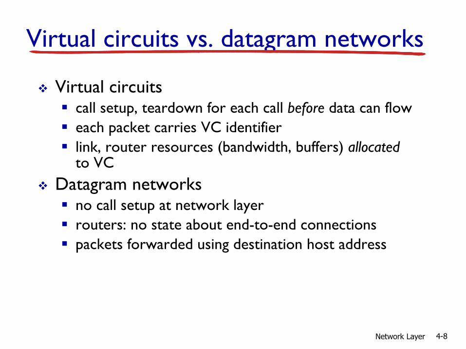
Virtual circuits vs. datagram networks
Virtual circuits call setup, teardown for each call before data can flow
each packet carries VC identifier
link, router resources (bandwidth, buffers) allocated to VC
Datagram networks no call setup at network layer
routers: no state about end-to-end connections
packets forwarded using destination host address

Network Layer 4-9
Longest prefix matching
when looking for forwarding table entry for given destination address, use longest address prefix that matches destination address.
longest prefix matching
Destination Address Range
11001000 00010111 00010*** *********
11001000 00010111 00011000 *********
11001000 00010111 00011*** *********
otherwise
Link interface
0
1
2
3

Network Layer 4-10
4.1 introduction
4.2 virtual circuit and datagram networks
4.3 what’s inside a router
4.4 IP: Internet Protocol datagram format
IPv4 addressing
ICMP
IPv6
4.5 routing algorithms link state
distance vector
hierarchical routing
4.6 routing in the Internet RIP
OSPF
BGP
4.7 broadcast and multicast routing
Chapter 4: outline

Network Layer 4-11
Router architecture overviewtwo key router functions: run routing algorithms/protocol (RIP, OSPF, BGP)
forwarding datagrams from incoming to outgoing link
high-seed switching
fabric
routing processor
router input ports router output ports
forwarding data
plane (hardware)
routing, management
control plane (software)
forwarding tables computed,
pushed to input ports

Network Layer 4-12
line
termination
link layer
protocol(receive)
lookup,
forwarding
queueing
Input port functions
decentralized switching:
given datagram dest., lookup output port using forwarding table in input port memory (“match plus action”)
goal: complete input port processing at ‘line speed’
queuing: if datagrams arrive faster than forwarding rate into switch fabric
physical layer:
bit-level reception
data link layer:
e.g., Ethernet
see chapter 5
switchfabric

Network Layer 4-13
Switching fabrics
transfer packet from input buffer to appropriate output buffer
switching rate: rate at which packets can be transfer from inputs to outputs often measured as multiple of input/output line rate
N inputs: switching rate N times line rate desirable
three types of switching fabrics
memory
memory
bus crossbar

Network Layer 4-14
Switching via memory
first generation routers: traditional computers with switching under direct control
of CPU
packet copied to system’s memory
speed limited by memory bandwidth (2 bus crossings per datagram)
inputport(e.g.,
Ethernet)
memory
outputport(e.g.,
Ethernet)
system bus

RouteTable
CPUBufferMemory
LineInterface
MAC
LineInterface
MAC
LineInterface
MAC
Typically < 1Gbps aggregate capacityLimited by rate of shared memory
Shared Backplane
Shared Memory Switches

Network Layer 4-16
Switching via a bus
datagram from input port memory
to output port memory via a shared bus
bus contention: switching speed limited by bus bandwidth
32 Gbps bus, Cisco 5600: sufficient speed for access and enterprise routers
bus

RouteTable
CPU
LineCard
BufferMemory
LineCard
MAC
BufferMemory
LineCard
MAC
BufferMemory
FwdingCache
FwdingCache
FwdingCache
MAC
BufferMemory
Typically < 50Gb/s aggregate capacity; Limited by shared bus
Shared Bus Switches

Network Layer 4-18
Switching via interconnection network
overcome bus bandwidth limitations
banyan networks, crossbar, other interconnection nets initially developed to connect processors in multiprocessor
advanced design: fragmenting datagram into fixed length cells, switch cells through the fabric.
Cisco 12000: switches 60 Gbps through the interconnection network

LineCard
MAC
LocalBuffer
Memory
CPUCard
LineCard
MAC
LocalBuffer
Memory
Switched Backplane
FwdingTable
RoutingTable
FwdingTable
Typically < 1000Gbpsaggregate capacity
Crossbar Switches

Network Layer 4-20
Output ports
buffering required when datagrams arrive from fabric faster than the transmission rate
scheduling discipline chooses among queued datagrams for transmission
line
termination
link layer
protocol(send)
switchfabric
datagram
buffer
queueing

Network Layer 4-21
Output port queueing
buffering when arrival rate via switch exceeds output line speed
queueing (delay) and loss due to output port buffer overflow!
at t, packets more
from input to output
one packet time later
switch
fabric
switch
fabric

Network Layer 4-22
Input port queuing
fabric slower than input ports combined -> queueing may occur at input queues
queueing delay and loss due to input buffer overflow!
Head-of-the-Line (HOL) blocking: queued datagram at front of queue prevents others in queue from moving forward
output port contention:
only one red datagram can be
transferred.
lower red packet is blocked
switch
fabric
one packet time later:
green packet
experiences HOL
blocking
switch
fabric

Output 1
Output 2
Output 3
Input 1
Input 2
Input 3
Solution to HOL Blocking
Maintain N virtual queues at each input port.
Packets to different destinations in different queues.
Network Layer 4-23

Network Layer 4-24
4.1 introduction
4.2 virtual circuit and datagram networks
4.3 what’s inside a router
4.4 IP: Internet Protocol datagram format
IPv4 addressing
ICMP
IPv6
4.5 routing algorithms link state
distance vector
hierarchical routing
4.6 routing in the Internet RIP
OSPF
BGP
4.7 broadcast and multicast routing
Chapter 4: outline

Network Layer 4-25
ver length
32 bits
data
(variable length,
typically a TCP
or UDP segment)
16-bit identifier
header
checksum
time to
live
32 bit source IP address
head.
len
type of
service
flgsfragment
offsetupper
layer
32 bit destination IP address
options (if any)
IP datagram formatIP protocol version
number
header length
(bytes)
upper layer protocol
to deliver payload to
total datagram
length (bytes)
“type” of data for
fragmentation/
reassemblymax number
remaining hops
(decremented at
each router)
e.g. timestamp,
record route
taken, specify
list of routers
to visit.
how much overhead?
20 bytes of TCP
20 bytes of IP
= 40 bytes + app layer overhead

Network Layer 4-26
IP fragmentation, reassembly
network links have MTU (max.transfer size) -largest possible link-level frame
different link types, different MTUs
large IP datagram divided (“fragmented”) within net
one datagram becomes several datagrams
“reassembled” only at final destination
IP header bits used to identify, order related fragments
fragmentation:
in: one large datagram
out: 3 smaller datagrams
reassembly
…
…

Network Layer 4-27
ID
=xoffset
=0
fragflag
=0
length
=4000
ID
=xoffset
=0
fragflag
=1
length
=1500
ID
=xoffset
=185
fragflag
=1
length
=1500
ID
=xoffset
=370
fragflag
=0
length
=1040
one large datagram becomes
several smaller datagrams
example: 4000 byte datagram
MTU = 1500 bytes
1480 bytes in
data field
offset =
1480/8
IP fragmentation, reassembly

Example
Consider sending a 2400-byte datagram into a link that has an MTU of 700 bytes. Suppose the original datagram is stamped with the identification number 422.
Assuming a 20-byte IP header, how many fragments are generated?
What are the values in the various fields in the IP datagrams generated related to fragmentation?
Network Layer 4-28

Network Layer 4-29
4.1 introduction
4.2 virtual circuit and datagram networks
4.3 what’s inside a router
4.4 IP: Internet Protocol datagram format
IPv4 addressing
ICMP
IPv6
4.5 routing algorithms link state
distance vector
hierarchical routing
4.6 routing in the Internet RIP
OSPF
BGP
4.7 broadcast and multicast routing
Chapter 4: outline

Network Layer 4-30
IP addressing: introduction
IP address: 32-bit identifier for host, router interface
interface: connection between host/router and physical link router’s typically have
multiple interfaces
host typically has one or two interfaces (e.g., wired Ethernet, wireless 802.11)
IP addresses associated with each interface
223.1.1.1
223.1.1.2
223.1.1.3
223.1.1.4 223.1.2.9
223.1.2.2
223.1.2.1
223.1.3.2223.1.3.1
223.1.3.27
223.1.1.1 = 11011111 00000001 00000001 00000001
223 1 11

Network Layer 4-31
Subnets
IP address:subnet part - high order bits
host part - low order bits
what’s a subnet ?device interfaces with same subnet part of IP address
can physically reach each other without intervening router network consisting of 3 subnets
223.1.1.1
223.1.1.3
223.1.1.4 223.1.2.9
223.1.3.2223.1.3.1
subnet
223.1.1.2
223.1.3.27223.1.2.2
223.1.2.1
Network Layer 4-32
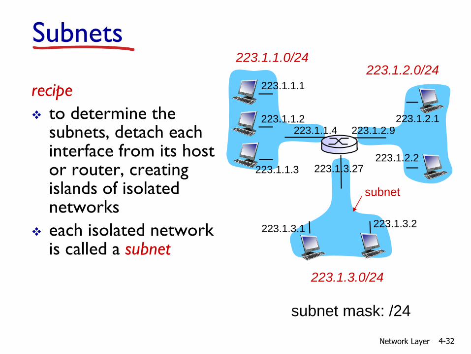
recipe
to determine the subnets, detach each interface from its host or router, creating islands of isolated networks
each isolated network is called a subnet
subnet mask: /24
Subnets223.1.1.0/24
223.1.2.0/24
223.1.3.0/24
223.1.1.1
223.1.1.3
223.1.1.4 223.1.2.9
223.1.3.2223.1.3.1
subnet
223.1.1.2
223.1.3.27223.1.2.2
223.1.2.1

Network Layer 4-33
how many? 223.1.1.1
223.1.1.3
223.1.1.4
223.1.2.2223.1.2.1
223.1.2.6
223.1.3.2223.1.3.1
223.1.3.27
223.1.1.2
223.1.7.0
223.1.7.1
223.1.8.0223.1.8.1
223.1.9.1
223.1.9.2
Subnets

IPv4 Classful Addressing
34

Network Layer 4-35
IP addressing: CIDR
CIDR: Classless InterDomain Routing subnet portion of address of arbitrary length
address format: a.b.c.d/x, where x is # bits in subnet portion of address
11001000 00010111 00010000 00000000
subnet
part
host
part
200.23.16.0/23

Example
Consider a router that interconnects three subnets: Subnet 1, 2, and 3. All of the interfaces in each of these three subnets are required to have the prefix 223.1.17.0/24.
a. Suppose that Subnet 1 is required to support up to 128 interfaces. Provide the network address (of the form a.b.c.d/x) for Subnet 1.
b. Suppose that Subnet 2 is required to support up to 55 interfaces. Provide the network address (of the form a.b.c.d/x) for Subnet 2, without conflicting with the address of Subnet 1.
Network Layer 4-36

Network Layer 4-37
IP addresses: how to get one?
Q: How does a host get IP address?
hard-coded by system admin in a file Windows: control-panel->network->configuration-
>tcp/ip->properties
UNIX: /etc/rc.config
DHCP: Dynamic Host Configuration Protocol: dynamically get address from as server
“plug-and-play”

Network Layer 4-38
DHCP: Dynamic Host Configuration Protocol
goal: allow host to dynamically obtain its IP address from network server when it joins network
can renew its lease on address in use
allows reuse of addresses (only hold address while connected/“on”)
support for mobile users who want to join network (more shortly)
DHCP overview: host broadcasts “DHCP discover” msg [optional]
DHCP server responds with “DHCP offer” msg [optional]
host requests IP address: “DHCP request” msg
DHCP server sends address: “DHCP ack” msg

Network Layer 4-39
DHCP client-server scenario
223.1.1.0/24
223.1.2.0/24
223.1.3.0/24
223.1.1.1
223.1.1.3
223.1.1.4 223.1.2.9
223.1.3.2223.1.3.1
223.1.1.2
223.1.3.27223.1.2.2
223.1.2.1
DHCPserver
arriving DHCPclient needs address in thisnetwork

Network Layer 4-40
DHCP server: 223.1.2.5 arrivingclient
DHCP discover
src : 0.0.0.0, 68
dest.: 255.255.255.255,67
yiaddr: 0.0.0.0
transaction ID: 654
DHCP offer
src: 223.1.2.5, 67
dest: 255.255.255.255, 68
yiaddrr: 223.1.2.4
transaction ID: 654
lifetime: 3600 secs
DHCP request
src: 0.0.0.0, 68
dest:: 255.255.255.255, 67
yiaddrr: 223.1.2.4
transaction ID: 655
lifetime: 3600 secs
DHCP ACK
src: 223.1.2.5, 67
dest: 255.255.255.255, 68
yiaddrr: 223.1.2.4
transaction ID: 655
lifetime: 3600 secs
DHCP client-server scenario

Network Layer 4-41
DHCP: more than IP addresses
DHCP can return more than just allocated IP address on subnet: address of first-hop router for client
name and IP address of DNS sever
network mask (indicating network versus host portion of address)

Network Layer 4-42
connecting laptop needs its IP address, addr of first-hop router, addr of DNS server: use DHCP
router with DHCP
server built into
router
DHCP request encapsulated in UDP, encapsulated in IP, encapsulated in 802.1 Ethernet
Ethernet frame broadcast (dest: FFFFFFFFFFFF) on LAN, received at router running DHCP server
Ethernet demuxed to IP demuxed, UDP demuxed to DHCP
168.1.1.1
DHCP
UDP
IP
Eth
Phy
DHCP
DHCP
DHCP
DHCP
DHCP
DHCP
UDP
IP
Eth
Phy
DHCP
DHCP
DHCP
DHCPDHCP
DHCP: example

Network Layer 4-43
DCP server formulates DHCP ACK containing client’s IP address, IP address of first-hop router for client, name & IP address of DNS server
encapsulation of DHCP server, frame forwarded to client, demuxing up to DHCP at client
DHCP: example
router with DHCP
server built into
router
DHCP
DHCP
DHCP
DHCP
DHCP
UDP
IP
Eth
Phy
DHCP
DHCP
UDP
IP
Eth
Phy
DHCP
DHCP
DHCP
DHCP
client now knows its IP address, name and IP address of DSN server, IP address of its first-hop router

Network Layer 4-44
IP addresses: how to get one?
Q: how does network get subnet part of IP addr?
A: gets allocated portion of its provider ISP’s address space
ISP's block 11001000 00010111 00010000 00000000 200.23.16.0/20
Organization 0 11001000 00010111 00010000 00000000 200.23.16.0/23
Organization 1 11001000 00010111 00010010 00000000 200.23.18.0/23
Organization 2 11001000 00010111 00010100 00000000 200.23.20.0/23
... ….. …. ….
Organization 7 11001000 00010111 00011110 00000000 200.23.30.0/23

Network Layer 4-45
Hierarchical addressing: route aggregation
“Send me anything
with addresses
beginning
200.23.16.0/20”
200.23.16.0/23
200.23.18.0/23
200.23.30.0/23
Fly-By-Night-ISP
Organization 0
Organization 7Internet
Organization 1
ISPs-R-Us“Send me anything
with addresses
beginning
199.31.0.0/16”
200.23.20.0/23
Organization 2
.
.
.
.
.
.
hierarchical addressing allows efficient advertisement of routing
information:

Network Layer 4-46
IP addressing: the last word...
Q: how does an ISP get block of addresses?
A: ICANN: Internet Corporation for Assigned
Names and Numbers http://www.icann.org/
allocates addresses
manages DNS
assigns domain names, resolves disputes

Network Layer 4-47
NAT: network address translation
10.0.0.1
10.0.0.2
10.0.0.3
10.0.0.4
138.76.29.7
local network
(e.g., home network)
10.0.0/24
rest of
Internet
datagrams with source or destination in this networkhave 10.0.0/24 address for source, destination (as usual)
all datagrams leaving localnetwork have same single
source NAT IP address: 138.76.29.7,different source
port numbers
Network Layer 4-48
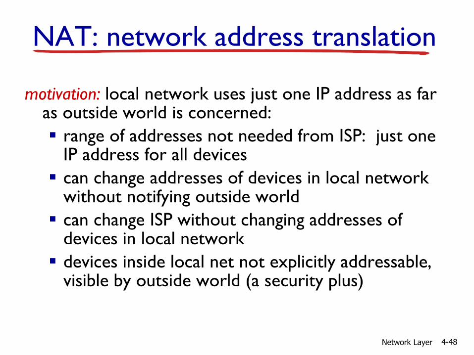
motivation: local network uses just one IP address as far as outside world is concerned:
range of addresses not needed from ISP: just one IP address for all devices
can change addresses of devices in local network without notifying outside world
can change ISP without changing addresses of devices in local network
devices inside local net not explicitly addressable, visible by outside world (a security plus)
NAT: network address translation

Network Layer 4-49
implementation: NAT router must:
outgoing datagrams: replace (source IP address, port #) of every outgoing datagram to (NAT IP address, new port #)
. . . remote clients/servers will respond using (NAT IP address, new port #) as destination addr
remember (in NAT translation table) every (source IP address, port #) to (NAT IP address, new port #) translation pair
incoming datagrams: replace (NAT IP address, new port #) in dest fields of every incoming datagram with corresponding (source IP address, port #) stored in NAT table
NAT: network address translation

Network Layer 4-50
10.0.0.1
10.0.0.2
10.0.0.3
S: 10.0.0.1, 3345
D: 128.119.40.186, 80
1
10.0.0.4
138.76.29.7
1: host 10.0.0.1 sends datagram to 128.119.40.186, 80
NAT translation table
WAN side addr LAN side addr
138.76.29.7, 5001 10.0.0.1, 3345
…… ……
S: 128.119.40.186, 80
D: 10.0.0.1, 33454
S: 138.76.29.7, 5001
D: 128.119.40.186, 802
2: NAT routerchanges datagramsource addr from10.0.0.1, 3345 to138.76.29.7, 5001,updates table
S: 128.119.40.186, 80
D: 138.76.29.7, 5001 3
3: reply arrivesdest. address:138.76.29.7, 5001
4: NAT routerchanges datagramdest addr from138.76.29.7, 5001 to 10.0.0.1, 3345
NAT: network address translation

Network Layer 4-51
NAT traversal problem
client wants to connect to server with address 10.0.0.1 server address 10.0.0.1 local to
LAN (client can’t use it as destination addr)
only one externally visible NATed address: 138.76.29.7
solution1: statically configure NAT to forward incoming connection requests at given port to server e.g., (123.76.29.7, port 2500)
always forwarded to 10.0.0.1 port 25000
10.0.0.1
10.0.0.4
NAT router
138.76.29.7
client
?

Network Layer 4-52
NAT traversal problem
solution 2: Universal Plug and Play (UPnP) Internet Gateway Device (IGD) Protocol. Allows NATed host to: learn public IP address
(138.76.29.7) add/remove port mappings
(with lease times)
i.e., automate static NAT port map configuration
10.0.0.1
NAT router
IGD

Network Layer 4-53
NAT traversal problem
solution 3: relaying (used in Skype)
NATed client establishes connection to relay
external client connects to relay
relay bridges packets between two connections
138.76.29.7
client
1. connection torelay initiatedby NATed host
2. connection torelay initiatedby client
3. relaying established
NAT router
10.0.0.1

Network Layer 4-54
4.1 introduction
4.2 virtual circuit and datagram networks
4.3 what’s inside a router
4.4 IP: Internet Protocol datagram format
IPv4 addressing
ICMP
IPv6
4.5 routing algorithms link state
distance vector
hierarchical routing
4.6 routing in the Internet RIP
OSPF
BGP
4.7 broadcast and multicast routing
Chapter 4: outline

Network Layer 4-55
ICMP: internet control message protocol
used by hosts & routers to communicate network-level information error reporting:
unreachable host, network, port, protocol
echo request/reply (used by ping)
network-layer “above” IP: ICMP msgs carried in IP
datagrams
ICMP message: type, code plus first 8 bytes of IP datagram causing error
Type Code description
0 0 echo reply (ping)
3 0 dest. network unreachable
3 1 dest host unreachable
3 2 dest protocol unreachable
3 3 dest port unreachable
3 6 dest network unknown
3 7 dest host unknown
4 0 source quench (congestion
control - not used)
8 0 echo request (ping)
9 0 route advertisement
10 0 router discovery
11 0 TTL expired
12 0 bad IP header

Network Layer 4-56
Traceroute and ICMP
source sends series of UDP segments to dest first set has TTL =1
second set has TTL=2, etc.
unlikely port number
when nth set of datagrams arrives to nth router: router discards datagrams
and sends source ICMP messages (type 11, code 0)
ICMP messages includes name of router & IP address
when ICMP messages arrives, source records RTTs
stopping criteria:
UDP segment eventually arrives at destination host
destination returns ICMP “port unreachable”message (type 3, code 3)
source stops
3 probes
3 probes
3 probes

Network Layer 4-57
IPv6: motivation
initial motivation: 32-bit address space soon to be completely allocated.
additional motivation: header format helps speed processing/forwarding
header changes to facilitate QoS
IPv6 datagram format: fixed-length 40 byte header
no fragmentation allowed

Network Layer 4-58
IPv6 datagram format
priority: identify priority among datagrams in flow
flow Label: identify datagrams in same “flow.”(concept of “flow” not well defined).
next header: identify upper layer protocol for data
data
destination address(128 bits)
source address(128 bits)
payload len next hdr hop limit
flow labelpriver
32 bits

Network Layer 4-59
Other changes from IPv4
checksum: removed entirely to reduce processing time at each hop
options: allowed, but outside of header, indicated by “Next Header” field
ICMPv6: new version of ICMP additional message types, e.g. “Packet Too Big” multicast group management functions