high voltage protection - download.e-bookshelf.de
TRANSCRIPT


High Voltage Protection for Telecommunications

IEEE Press445 Hoes Lane
Piscataway, NJ 08854
IEEE Press Editorial BoardLajos Hanzo, Editor in Chief
R. Abhari M. El-Hawary O. P. Malik
J. Anderson B-M. Haemmerli S. Nahavandi
G. W. Arnold M. Lanzerotti T. Samad
F. Canavero D. Jacobson G. Zobrist
Kenneth Moore, Director of IEEE Book and Information Services (BIS)

High Voltage Protection for Telecommunications
Steven W. BlumeCarlsbad, California
IEEE PRESS
A John Wiley & Sons, Inc., Publication
Mohamed E. El-Hawary, Series Editor

Copyright © 2011 by the Institute of Electrical and Electronics Engineers, Inc.
Published by John Wiley & Sons, Inc., Hoboken, New Jersey. All rights reserved.Published simultaneously in Canada
No part of this publication may be reproduced, stored in a retrieval system, or transmitted in any form or by any means, electronic, mechanical, photocopying, recording, scanning, or otherwise, except as permitted under Section 107 or 108 of the 1976 United States Copyright Act, without either the prior written permission of the Publisher, or authorization through payment of the appropriate per-copy fee to the Copyright Clearance Center, Inc., 222 Rosewood Drive, Danvers, MA 01923, (978) 750-8400, fax (978) 750-4470, or on the web at www.copyright.com. Requests to the Publisher for permission should be addressed to the Permissions Department, John Wiley & Sons, Inc., 111 River Street, Hoboken, NJ 07030, (201) 748-6011, fax (201) 748-6008, or online at http://www.wiley.com/go/permissions.
Limit of Liability/Disclaimer of Warranty: While the publisher and author have used their best efforts in preparing this book, they make no representations or warranties with respect to the accuracy or completeness of the contents of this book and specifically disclaim any implied warranties of merchantability or fitness for a particular purpose. No warranty may be created or extended by sales representatives or written sales materials. The advice and strategies contained herein may not be suitable for your situation. You should consult with a professional where appropriate. Neither the publisher nor author shall be liable for any loss of profit or any other commercial damages, including but not limited to special, incidental, consequential, or other damages.
For general information on our other products and services or for technical support, please contact our Customer Care Department within the United States at (800) 762-2974, outside the United States at (317) 572-3993 or fax (317) 572-4002.
Wiley also publishes its books in a variety of electronic formats. Some content that appears in print may not be available in electronic formats. For more information about Wiley products, visit our web site at www.wiley.com.
Library of Congress Cataloging-in-Publication Data:Blume, Steven Warren. High voltage protection for telecommunications / Steven Blume.—1st ed. p. cm.—(IEEE press series on power engineering ; 44) ISBN 978-0-470-27681-5 (hardback) 1. Telecommunication–Equipment and supplies–Protection. 2. Telecommunication lines–Protection. 3. Transients (Electricity) 4. Overvoltage–Prevention. I. Title. TK5103.B58 2011 621.382028'4–dc23 2011018344
Printed in the United States of America
oBook ISBN: 9781118127018ePDF ISBN: 9781118127056ePub ISBN: 9781118127100eMobi ISBN: 9781118127032
10 9 8 7 6 5 4 3 2 1
v
Preface ix
Acknowledgments xiii
AbouttheAuthor xv
1 OverviewofHighVoltageProtectionforTelecommunications 1Basic Purpose and Applications, 2The HV Protection Challenge, 3HV Isolation Standards, 7
2 ElectricPowerSystemFundamentals 11Power Terminology for Telecommunications, 12Electric Power System Overview, 21AC Voltage Generation, 23Substation Equipment, 31Transmission Lines, 44Distribution Lines, 45System Protection Equipment and Concepts, 47
3 GroundPotentialRise(GPR)andZoneofInfluence 63Introduction to Ground Potential Rise (GPR), 64GPR, 65GPR Locations, 66Factors Affecting GPR, 71Calculation of GPR, 86ZOI, 88
Contents

vi Contents
Earth Resistivity, 91GPR and ZOI Calculation Methods, 95Lightning Faults, 107Electromagnetic Induction under Fault Conditions, 109Total Electrical Cable Stress, 118The Role of Protection Engineers, 119
4 CriticalTelecommunicationsCircuitsinHVEnvironments 121General, 122Service Performance Objectives (SPOs), 122North America Electric Reliability Corporation (NERC)
Critical Infrastructure Protection (CIP) Standards, 125Protective Relaying Schemes that Require Class A
Circuits, 126Power Applications that Require Class B Circuits, 131Power Communication Service Types, 136Smart Grid and Cyber Security, 139
5 HighVoltageProtectionEquipment 143General, 144Basic Shunt Protection, 144Levels of Protection, 149Special Consideration for Nearby Facilities, 166
6 LevelIIIHVProtectionEquipment,Installation,andTesting 167General, 168Level III Copper HVI Components, 169Copper HVI System Design, 181Copper HVI Installation Examples, 191Copper HVI System Initial Testing, 195Copper HVI Maintenance and Inspection, 197Fiber HVI Systems Installation, 199Fiber HVI Installation Examples, 202Wireless Sites on Electrical Power Towers, 205Protection at Non-Power Company Locations, 211

Contents vii
7 PersonnelSafetyWorkingwithHVProtectionEquipment 217Electrical Safety, 218Electrical Protection Priorities, 218Touch and Step Potentials, 219
Glossary 227
Appendix:ServiceRequestForm 231
Bibliography 235
Index 237


ix
ABOUT THE BOOK
This book is intended to help electric power and telephone company personnel and individuals interested in properly protecting critical telecommunications circuits and equipment located in high voltage (HV) environments and to improve service reliability while maintaining safe working conditions. Critical telecommunications circuits are often located in HV environments such as electric utility power plants, substations, cell sites on power towers, and standalone telecommunications facilities such as 911 call centers and mountaintop telecommunications sites. The need for highly reliable telecommunications circuits during power faults and lightning strikes when controlling our nation’s electric power grids, communicating via wireless phones, and conversing with public safety support individuals at 911 call centers has never been higher. The utilization of information provided in this book should help provide higher reliable telecommunications circuits and improve the safety of personnel working in HV environments. Several industry standards and best practices are referenced throughout this book. These standards and practices are based on power and telecommunications company experience, field testing, workgroup committees, equipment manufacturers’ support, and the advice of construction contractors and industry experts/consultants. This book is very comprehensive in that it combines several detailed references into a practical general purpose applications reference guide.
There is a power and telecommunications industry concern that a high percentage of people knowledgeable in this subject area have either retired or are approaching retirement, and these industries are losing valuable expertise for proper application solutions. This book is intended for individuals new to this subject area who want a working knowledge of the concepts, design techniques, and industry’s best practices. Likewise, subject area professionals require knowledge of the dos and don’ts regarding the special electrical phenomena that affect
Preface

x Preface
telecommunications circuits that are required to be reliable and safe to maintain.
The target audience is managers, engineers, planners, and technicians involved in protecting critical telecommunications circuits from the adverse effects of electric power faults and lightning strikes. Personnel in public safety, natural gas, water, public utilities, and others involved in assuring that critical telecommunications circuits are reliable under lightning conditions should find benefit from reading this book.
What is not covered in this book are the details surrounding each type of telecommunications circuit such as digital subscriber line (DSL), high speed DSL, T1, plain old telephone service, the difference between twowire and fourwire circuits, and so on. This information is readily available on the Internet and from other resources such as the following:
• Subscriber Loop Signaling and Transmission Handbook–– Analog by Whitman D. Reeve
• Subscriber Loop Signaling and Transmission Handbook–– Digital by Whitman D. Reeve
Also not included in this book are the vendorspecific details of their proprietary HV isolation equipment and details contained in the referenced industry standards. The focus here is to explain how such critical circuits are protected from lightning strikes and power faults, plus the safe handling of such circuits should a power fault or lightning strike occur at the time of construction or maintenance.
This book provides a helpful reference to implement concepts correctly and to recognize situations to avoid. The reader should also be aware that sophisticated computer programs and consulting services are readily available for guidance with unique circumstances that may not be covered in this book. This book does provide the knowledge and background necessary to work closely with consultants or to understand the principles of sophisticated computer programs.
CHAPTER SUMMARIES
A brief overview of each chapter is presented below to summarize the flow of technical information and to help identify what and where specific topics are covered in this book.

Preface xi
Chapter 1 presents an overview of high voltage protection for telecommunications (HVPT). The book starts out with a brief yet informative discussion of the impending problems that can occur when critical telecommunications circuits exist in HV environments. The purpose of this chapter is to quickly familiarize the reader with the important issues, industry standard solutions, and safety aspects affecting telecommunications reliability during lightning and power fault situations.
Chapter 2 discusses the fundamentals of electric power systems to help readers who are unfamiliar with HV equipment become better acquainted with HVPT applications. A basic model of the overall electric power system is presented to establish a fundamental understanding of how power systems work and the electrical phenomena that can interrupt critical telecommunications circuits and, if the system is not properly protected, cause equipment damage and injury to personnel. This chapter explains how substation ground grids, protective relaying, fault clearing devices, lightning arresters, and telecommunications equipment are used to clear power faults to minimize equipment damage and maximize electric service reliability.
Chapter 3 elaborates on the concepts of ground potential rise (GPR) and zone of influence (ZOI). These two concepts are fundamental to this subject area, and proper protection design, installation, and maintenance depend on a solid understanding of these concepts. The definitions, causes, boundary conditions, and calculations of GPR and ZOI are discussed in this chapter.
The critical telecommunications circuits found in HV environments are discussed in Chapter 4. The various classes and types of critical telecommunications circuits used by power and telecommunications companies and public service providers where HV protection is necessary are also discussed. Examples of situations which require HV protection are the critical electric power systems control centers and associated protective relaying applications, telephone companies that are using telecommunications circuits involving wireless radio equipment mounted on HV electric power towers, and 911 call centers, which have their respective requirements for critical circuit reliability. The standard service performance objectives (SPOs) and standard levels of protection are discussed in this chapter.
Chapter 5 presents discussions about the actual HV protection equipment used in these critical circuit situations. The concepts behind modern telecommunications protection schemes and equipment used

xii Preface
to resolve GPR problems are also discussed, as well as references to industry standards and typical manufacture equipment offerings.
Chapter 6 discusses proper installation and testing procedures of high voltage interface (HVI) equipment. The design and installation objectives, both theoretical and physical, for reliable HV isolation are the focus points of this chapter. Proper design and installation is paramount; however, attention is given to the dos, don’ts, and common installation deficiencies. Photographs of actual installed equipment configurations are included in this chapter to give the reader a practical perspective.
Safety in working with HV equipment is the main topic of Chapter 7. The safety of personnel who work with HV protection equipment is a paramount concern for supervisors and managers responsible for technicians and field personnel. For example, telephone company personnel who work in electric power substations must be aware of all safety rules and procedures and proper use, inspection, and testing of personal protective equipment (PPE) before entering a substation or power plant. The reader will be made aware of these safety concerns and how and when to properly use PPE.
DISCLAIMER
This book is not intended to ensure safety of personnel nor to ensure that equipment will not be damaged should a power fault or lightning strike event occur. The advice, suggestions, and recommendations contained in this book are presented for general educational purposes only and to increase safety awareness regarding HV protection for telecommunications. The information presented in this book is based on applicable industry standards and best practices. This book is not intended to be a legal or other expert advice resource and should not be used in place of highly qualified professional consultants. The information in this book is considered accurate and helpful but is not to be considered exhaustive and complete. The responsibility for safe and reliable equipment in HV environments always remains the responsibility of the parties doing the work.
Steven W. Blume

xiii
I would personally like to thank several people who have contributed to the success of my career and the success of this book. To my wife Maureen who has been supporting me for over 40 years, thank you for your guidance, understanding, encouragement, and so much more. Thank you Bill Ackerman, Dick Knight, Percy Pool, Tim Conser, Larry Young, Ernie Duckworth, Chuck Keller, and Rich Minetto for your unbiased technical support, help, and encouragement over the several years we have worked together in this field. I would also like to thank Positron Inc. and RLH Industries, Inc. for their photo contributions and equipment expertise.
S.W.B.
Acknowledgments


xv
Steven W. Blume is a registered professional engineer with over 40 years’ experience in the areas of electric power systems and telecom-munications. He holds a master’s degree specializing in electrical power systems and a bachelor’s degree specializing in telecommunica-tions technologies. He has worked in both the telecommunications industry (City of Los Angeles Police and Fire critical telecommunica-tions) and electric power industry (Sierra Pacific Power Company [now NV Energy]) in planning, design, operations, and construction of high voltage power facilities and telecommunications systems. Steve has been teaching high voltage protection for telecommunications (HVPT) courses for over 15 years. His combined knowledge, experience, and recognized ability to explain complex subjects in the simple-to- understand terms presented in this book will be useful to those inter-ested in gaining a working knowledge in HVPT applications.
About the Author
For more information on online, instructor-led, and private custom training opportunities, please visit the Web site www.aptc.edu or call Applied Professional Training, Inc.: (800) 431-8488.


1
High Voltage Protection for Telecommunications, First Edition. Steven W. Blume.© 2011 the Institute of Electrical and Electronics Engineers, Inc. Published 2011 by John Wiley & Sons, Inc.
Overview of High Voltage Protection for Telecommunications
LEARNING OBJECTIVES
• Discuss the purpose of high voltage (HV) isolation protection equipment
• Describe ground potential rise (GPR) and how it can damage telecommunications equipment and expose people to unsafe working conditions
• Describe what is meant by zone of influence (ZOI) and the 300-V point
• Explain the problems encountered if HV isolation equipment is not used
• Explain where to install HV isolation equipment
• Describe the two main types of HV isolation equipment (copper vs. fiber) and the corresponding IEEE recommended practices for proper design and installation
• Explain how copper versus fiber HV isolation equipment works
CHAPTER 1

2 CHAPTER 1 Overview of High Voltage Protection for Telecommunications
BASIC PURPOSE AND APPLICATIONS
Copper wire-line telecommunication facilities (as opposed to fiber optics, radio, microwave, satellite, and power line carrier systems) that are used in electric supply locations (ESLs) often require special high voltage (HV) protection equipment to provide safety to personnel, to prevent damage to equipment, and to assure the reliable operation of the telecommunications circuits themselves. There are various means of properly protecting telecommunications facilities equipment and personnel. The goal of high voltage protection for telecommunications (HVPT) is to provide the design engineer with safe, reliable, and cost-effective installations when exposed to unexpected HV events such as power faults and lightning strikes. Power faults are HV flashovers of insulation, the breakdown of equipment used in HV systems, or when something happens to HV equipment causing it to discharge large amounts of electrical energy into its surroundings. When personnel are working in HV environments such as electric power substations, power plants, cell sites on power towers, and other potentially dangerous loca-tions where an HV event is possible, properly protecting critical tele-communications facilities is essential. Copper telecommunications cables can transfer dangerous potentials from remote locations due to their insulated jackets and remote connections. All dielectric optical fiber systems, on the other hand, offer electrical isolation due to the nonconductive properties of glass. This chapter summarizes the poten-tial problems with telecommunications circuits in HV environments, the industry solutions, and the recommended methods to work in these environments safely.
The first point to make in explaining the potential problem associ-ated with these facilities is to clarify the difference between HV “isola-tion” of telecommunications circuits and HV “protectors” used on telecommunications circuits. The terms are almost synonymous when it comes to protecting telecommunications circuits from HV conditions. Both terms apply to HV exposure conditions where circuits need to protect themselves from damage. However, the term HV “protectors” refers to circuit protection equipment that is used to limit the voltage across telecommunications circuit conductors by shunting the energy to the earth grounding electrodes (i.e., circuit protectors such as gas tubes and carbon blocks as discussed in more detail later in this book). The term HV isolation is used to describe circuit protection from HV
The HV Protection Challenge 3
damage by isolating the copper conductors from the damaging HV potentials. Shunt “protectors” are usually applicable to HVs 1000 V or less, and HV “isolation” devices are applicable to exposure HVs above 1000 V. Hence, both HV protectors and HV isolation equipment may be required at HV environments such as power substations, personal communications system (PCS) cell sites located on electric power towers, stand-alone mountaintop telecommunications antenna towers, and 911 emergency call centers. One of the main purposes of this book is to explain when and where to use shunt protectors and/or HV isola-tion equipment.
THE HV PROTECTION CHALLENGE
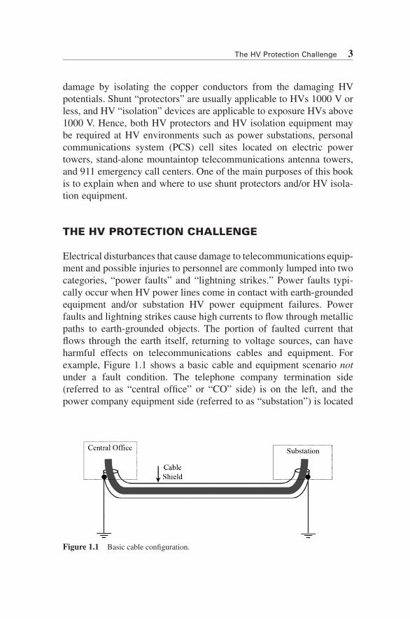
Electrical disturbances that cause damage to telecommunications equip-ment and possible injuries to personnel are commonly lumped into two categories, “power faults” and “lightning strikes.” Power faults typi-cally occur when HV power lines come in contact with earth-grounded equipment and/or substation HV power equipment failures. Power faults and lightning strikes cause high currents to flow through metallic paths to earth-grounded objects. The portion of faulted current that flows through the earth itself, returning to voltage sources, can have harmful effects on telecommunications cables and equipment. For example, Figure 1.1 shows a basic cable and equipment scenario not under a fault condition. The telephone company termination side (referred to as “central office” or “CO” side) is on the left, and the power company equipment side (referred to as “substation”) is located
Figure 1.1 Basic cable configuration.
4 CHAPTER 1 Overview of High Voltage Protection for Telecommunications
on the right. Notice that the cable shield is grounded on both ends (grounded is the term used to describe how the connection is made between the metal cable shield and the metal conductors buried in the earth). For the sake of illustration, intermediate grounds of the cable shield are not shown. In this case, the earth serves as a natural conduc-tive body that can potentially conduct electrical current should a voltage appear between the grounded objects. In the normal state, the earth has zero potential between these two grounded objects, and no current is flowing through the cable shield.
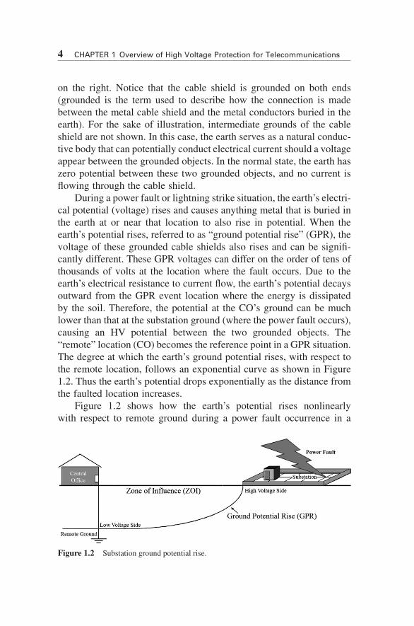
During a power fault or lightning strike situation, the earth’s electri-cal potential (voltage) rises and causes anything metal that is buried in the earth at or near that location to also rise in potential. When the earth’s potential rises, referred to as “ground potential rise” (GPR), the voltage of these grounded cable shields also rises and can be signifi-cantly different. These GPR voltages can differ on the order of tens of thousands of volts at the location where the fault occurs. Due to the earth’s electrical resistance to current flow, the earth’s potential decays outward from the GPR event location where the energy is dissipated by the soil. Therefore, the potential at the CO’s ground can be much lower than that at the substation ground (where the power fault occurs), causing an HV potential between the two grounded objects. The “remote” location (CO) becomes the reference point in a GPR situation. The degree at which the earth’s ground potential rises, with respect to the remote location, follows an exponential curve as shown in Figure 1.2. Thus the earth’s potential drops exponentially as the distance from the faulted location increases.
Figure 1.2 shows how the earth’s potential rises nonlinearly with respect to remote ground during a power fault occurrence in a
Figure 1.2 Substation ground potential rise.

The HV Protection Challenge 5
substation. The same is true with all ESLs. The HV GPR occurs at the substation in this case, and the low voltage (LV) side of the GPR is located at the “remote ground” location (the CO side in this case). Since the fault is located at the substation, the CO side is also referred to as the remote ground location. In other words, when a copper tele-communications cable is connected between the CO and a substation and both ends of the cable are grounded, the CO side is referred to as remote ground location, and the station side of the cable is referred to as the ESL.
The paramount issue is when the ESL (substation) side of the telecom-munications cable shield (or sheath) is connected to the substation’s ground conductors (i.e., ground grid) when a power fault occurs and GPR is created, the telecommunications equipment is likely to be damaged due to the large potential difference across the cable shield, and personnel injures are possible when equipment fails catastrophically. Further, per-sonal injury can also occur if the person comes in contact with both potentials at the same time. (These situations are discussed in more detail throughout this book.)
The distance between the HV fault location (substation) and the remote LV area is called the “zone of influence” (ZOI). Note that the LV location of the ZOI does not have to be the CO location. The ZOI is usually measured or calculated as the distance from the HV side (substation) to a point in the ZOI that measures or is calculated to be 300 V. This is referred to as the “300-V point.” Thus, the 300-V point is the location where the HV GPR decays exponentially to the 300-V level regardless of the magnitude of the GPR at the substation. For example, the substation GPR could be 30,000 V or 5000 V, and the ZOI is the distance to the 300-V point. The length or area of the ZOI depends on GPR magnitude and the soil type (details of GPR and ZOI are discussed later in this book).
Note that the “300-V point” is recommended in the United States, and other countries may use other values in a similar manner.
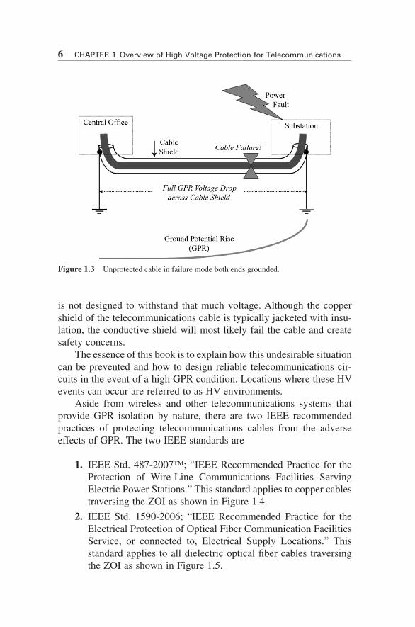
Combining the conditions of cable grounding at both ends, as in Figure 1.1, with the effects of earth’s GPR shown in Figure 1.2 when a power fault or lightning strike occurs, as in Figure 1.2, results in the possible cable damage and personal injury scenario shown in Figure 1.3. GPR is directly imposed on the copper cable and the copper cable
6 CHAPTER 1 Overview of High Voltage Protection for Telecommunications
is not designed to withstand that much voltage. Although the copper shield of the telecommunications cable is typically jacketed with insu-lation, the conductive shield will most likely fail the cable and create safety concerns.
The essence of this book is to explain how this undesirable situation can be prevented and how to design reliable telecommunications cir-cuits in the event of a high GPR condition. Locations where these HV events can occur are referred to as HV environments.
Aside from wireless and other telecommunications systems that provide GPR isolation by nature, there are two IEEE recommended practices of protecting telecommunications cables from the adverse effects of GPR. The two IEEE standards are
1. IEEE Std. 487-2007™; “IEEE Recommended Practice for the Protection of Wire-Line Communications Facilities Serving Electric Power Stations.” This standard applies to copper cables traversing the ZOI as shown in Figure 1.4.
2. IEEE Std. 1590-2006; “IEEE Recommended Practice for the Electrical Protection of Optical Fiber Communication Facilities Service, or connected to, Electrical Supply Locations.” This standard applies to all dielectric optical fiber cables traversing the ZOI as shown in Figure 1.5.
Figure 1.3 Unprotected cable in failure mode both ends grounded.

HV Isolation Standards 7
HV ISOLATION STANDARDS
There are two standard practices to protect telecommunications circuits in HV environments: those associated with copper cables crossing the ZOI and those associated with optical fiber cables crossing the ZOI. There are acceptable variations of the recommended practices, usually resulting in additional protection; however, minimum conditions must be met to assure equipment protection, personnel safety, and reliable circuit operations.
Copper Cables Crossing the ZOI (IEEE Std. 487-2007)
The most significant point to recognize when using copper telecom-munications cables across the ZOI is that the cable shield is not
Figure 1.4 Isolated copper cable in failure mode.
Figure 1.5 Isolated optical fiber cable in failure mode.
8 CHAPTER 1 Overview of High Voltage Protection for Telecommunications
grounded at both ends. The cable shield is grounded only at the remote ground location (300-V point, CO side) and isolated from all grounded conductors at the ESL and everywhere in the middle (see Fig. 1.4). Note that the cable shield is not connected directly to the substation ground grid.
The high voltage interface (HVI) is the telecommunications equip-ment that provides isolation from the voltage across the cable when the GPR occurs. Lightning arresters can be part of the HVI equipment. The lightning arrester protects the HVI when the GPR exceeds the insula-tion strength of the HVI by limiting the voltage across the HVI to the clamping voltage of the lightning arrested. When the GPR exceeds the breakdown voltage level of the arrester, the arrester conducts and limits or clamps the voltage across the HVI. The arrester is connected to the copper telecommunications cable between the cable shield and the station ground grid.
Lightning arresters are often installed at the substation end. The arrester connects the copper cable’s shield to the substation ground grid. The purposes of the lightning arrester are to limit the voltage potential across the HVI and to utilize the remote ground to help dissipate some lightning energy during extreme lightning strike conditions. During extreme lightning strike conditions, the lightning arrester conducts (fires) and helps dissipate lightning energy directly to the earth ground electrodes (the station ground grid in this example). Normally, the magnitude of the GPR is less than the firing voltage of the arrestor, and therefore the arrestor does nothing. Its purpose is to provide a second-ary path for extreme lightning energy should the substation side experi-ence an unusually high lightning event. Additionally, the arrester limits the voltage across the HVI, thus protecting the HVI from voltages exceeding its insulation capability.
The copper cable-type HVI accomplishes circuit isolation two ways; either through high dielectric strength transformer action (cou-pling through electromagnetics) or short-reach fiber optics (coupling through an optical interface).
Transformer HVI
The HVI equipment can be composed of transformer isolation, where the LV CO side is isolated from the HV station side through specially designed HV isolation transformers. These special transformers provide