high voltage physics
DESCRIPTION
High Voltage PhysicsTRANSCRIPT


J!Rdllltflt's j!ROnDgravhs on :l9hl1siral Sub.ttth~
General Editor: B. L. WORSNOP, B.Sc., Ph,.D.
HIGH VOLTAGE PHYSICS

METHUEN'S NIONOGRAPHS ONPHYSICAL SUBJECTS
F'cap Svo, 28. 6d. 'net each
Genewl Editor: B. L. WORSKOP, B.Sc., Ph.D.Head of the Department of Mathematics and Physics, The
Polytechnic, and Special Lecturer in Radiology,King's College, London
SPECTRA. By R. C. JOHNSON, D.Se. Second Edition, Revised.WAVE 1IECHAJ."UCS. By H. T. FUKT, D.Sc. Second Edition,
Revised and Enlarged. 38. 6d. net.THE PliYSICAL PRINCIPLES OF WIRELESS. Bv J. A.
RATCLIFFE, M.A. Third Edition, Revised and Enlarged.THE CONDUCTIO~OF ELECTRICITY THROVGH GASES.
By Professor K. G. El'rIELEUS, l\LA., Ph.D.MAG:\ETIS:\I. By E. C. STONER, Ph.D.X.RAYS. By B. L. WORSNOP, B.Sc., Ph.D.X·RAY CRYSTAI,LOGRAPHY. By R. W. JA~IES, lILA., B.Sc.THE COMMUTATOR MOTOR. By Professor F. J. TEAGO, D.Se.APPLICATIONS OF INTERFEROMETRY. By W. E.
WILLIAMS, M.sc.PHOTOCHEMISTRY. By D. W. G. STYLE, B.Sc., Ph.D.THERMODYNAMICS. By Professor A. W. PORTER, D.Se.,
F.R.S.THERMIONIC VACUUM TUBES. By Professor E. V.
APPLETON, M.A., D.Se.• F.R.S. Second Edition, R.vised.38. ne!.
WIRELESS RECEIVERS. By C. W. OATLEY, M.A., M.Sc.ATMOSPHERIC ELECTRICITY. By B. F. J. SCHONLAND,
M.A., Ph.D.THE METHOD OF DIMENSIONS. By Professor A. W. PORTER,
D.Se., F.R.S.COLLISION PROCESSES IN GASES. By F. L. ARNOT, B.Se.,
Ph.D. (Camb.l, F.R.S.E. 38. net.PHYSICAL CONSTANTS. By W. H. J. CHILDS, B.Se., Ph.D.ELECTROllIAGNETIC WAVES. By F. W. G. WHITE, M.Sc.
38. net.THE GENERAL PRINCIPLES OF QUANTUM THEORY.
By Professor G. TE~IPLE, Ph.D., D.Se. 38. net.THE KINETIC THEORY OF GASES. By Professor MARTIN
KNUDSEK.LOW TEMPERATURE PHYSICS. By L. C. JACKSON, M.Sc.
(Lond.), Doct. Wis. Nat. (Leiden). 38. net.HIGH VOLTAGE PHYSICS. By L. JACOB, M.Sc., A.R.C.Sc.L
38. net.RELATIVITY PHYSICS. By Professor W. H. MCCREA, lILA.,
B.Sc.In Preparation
SURFACE TENSION. By A. H. FERGCSON, M.A., D.Se.THE NUCLEUS. By Professor J. A. CROWTHER, M.A., Se.D.THERMIONIC EMISSION. By T. J. JONEs;.M.Se.FINE STRUCTURE IN LINE SPECTRA AND NUCLEAR
SPIN. Ry S. TOLANSKY, B.Sc., Ph.D.I~FRA-RED AND RAMAN SPECTRA. By Dr. G. B. B. M.
SUTHERLAKD.

HIGH VOLTAGE PHYSICS
by
L. JACOB, M.Sa., A.R.C.Sa.LA )fE~lBER OP THE RRSRARCH LABORATORIES OF THE GESRRAL
ELECTRIC C01-fPAXY LTD.
WITH 37 DIAGRA~{S
Distributed by
CHEMICAL PUBLISHING COMPANY OF N. Y., INC.
148 LAFAYETTE STREET, NEW YORK, N. Y., U. S. A.Technical Books Of ALL Publishers

First published in 1934
PRl~TED IN anEAT BRITAIN

AUTHOR'S PREFACE
Tms book gives a survey in outline of the Physics ofhigh voltage phenomena. Most of the results so farobtained on dielectrics are to some extent empirical,owing to the complex structure and behaviour of thematerials examined. Co.operation of the physical andcolloid chemist with the physicist would thus beprofitable in helping to elucidate some of the morefundamental aspects of dielectric behaviour. I havepurposely refrained from giving any detailed discussionof the radioactive IX and f1 radiations (considered ashigh velocity particles), as I anticipate they will beamply dealt with in this series.
I wish to express my best thanks to my colleaguesMr. B. S. Gossling, for his reading and criticism of thebulk of the manuscript, and Dr. W. G. Thompson, forreading the proofs. I also 'wish to express my indebtedness to the Director of these laboratories for perlllission
to publish Fig. 23 from some unpublished work donehere, and to the McGraw-Hill Book Co. for permissionto reproduce Figs. 22, 27, 32 from Peek's "DielectricPhenolllena.' ,
L. JACOB
RESEARCH LABORATORIES
'VEMBLEY, May, 1934
v

CONTENTS
PAGE
PREFACE VCHAPTER
I. PRODUCTION AND MEASUREMENT OF HIGH VOLTAGE
Electrostatic Generators. Transformers. VoltageMultiplying Circuits. Measurement of High Voltage.
II. ELECTRIC FIELDS 16
Electrode Forms. Combination of Dielectrics.
III. HIGH VOLTAGE ELECTRONS 21
Electron Waves. High Voltage Cathode Rays.Secondary Emission. Absorption and Transmission.Scattering.
IV. HIGH VOLTAGE POSITIVE IONS 42Sources and Circuits. Ionization. Secondary Emis-sion. Absorption and Scattering. Nuclear Bombardment.
V. Am AS A DIELECTRIC 53Discharge in Air at Small and Large Spacings.Corona. Effect of Pressure on Corona. Current inCorona Discharge. Sparkover. Paschen's Law.Sparkover: Electrode Systems. Spark Lag.
VI. SOLIDS AND LIQUIDS AS DIELECTRICS 68Abnormal Properties of Dielectrics. Conduction inSolid Dielectrics. Breakdown. Breakdown: Effectof Temperature. Breakdown: Power Loss andFrequency. Breakdown: Duration of Stress. LiquidDielectrics: Conduction. Liquid Dielectrics: Breakdown.
VII. VACUUM AS A DIELECTRIC 80Vacuum Arc. Schottky Effect. Field Currents.Conditioning of Surface. Field Current Characteris-tics. Field Currents: Temperature Effects. FlashArc.
BIBLIOGRAPHY
INDEX
vii
101
lOi,

HIGH VOLTAGE PHYSICS
CHAPTER I
PRODUCTION AND MEASUREMENT OF HIGHVOLTAGE
THE term high voltage is used to denote any voltagefrom about 1 kilovolt to 1000 kilovolts and over, andthis book is devoted to describing the effects of theapplication of such voltages to matter in its variousforms and under different physical conditions.
The high voltage is usually produced by machinesof one kind or another, which are so arranged that asa result of their operation, electromotive forces aregenerated at their terminals by the well-known effectsof electromagnetic or electrostatic induction.
Among those working on the former principle are thedirect-current dynamo, static transformers, inductioncoils, including Tesla coils, while the old Wimshurstmachine represents the principles on which the electrostatic generator depends. The high voltage is producedas continuous and unidirectional by the use of the directcurrent dynamo and electrostatic generator, and asalternating in character by the transformer and inductioncoil; however, it is possible to convert this alternating
.voltage into a continuous and unidirectional one bysuitable rectification and smoothing.
:YIention should of course be made here of the buildingup of a high voltage by the use of a very large number ofloW" voltage accumulators connected in series. Such a
1
2 HIGH VOLTAGE PHYSICS
s
+
++
+
+
FIG. I.-Electrostaticgenerator.
+
r------IUP,
battery giving 100 KV. and 40 mAo has been used atHarvard University, where extremely high precisionresults were aimed at. The initial expense and the carenecessary to keep the batteries in good condition reallypreclude their use to any large extent, particularly sincereliably constant voltage can now be obtained by asimpler method, and since the present-day tendency is
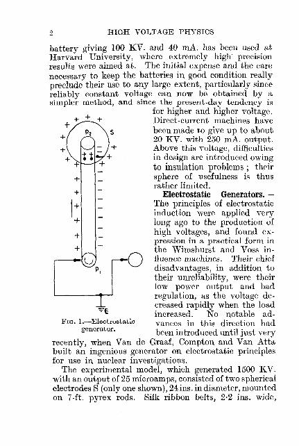
for higher and higher voltage.Direct-current machines havebeen made to give up to about20 KV. with 250 mAo output.Above this voltage, difficultiesin design are introduced owingto insulation problems; theirsphere of usefulness is thusrather limited.
Electrostatic Generators.The principles of electrostaticinduction were applied verylong ago to the production ofhigh voltages, and found expression in a practical form inthe Wimshurst and Voss in-G fluence machines. Their chiefdisadvantages, in addition totheir unreliability, were theirlow power output and badregulation, as the voltage decreased rapidly when the loadincreased. No notable advances in this direction hadbeen introduced until just very
recently, when Van de Graaf, Compton and Van Attabuilt an ingenious generator on electrostatic principlesfor use in nuclear investigations.
The experimental model, which generated 1500 KV.with an output of 25 microamps, consisted of two sphericalelectrodes S (only one shown), 24 ins. in diameter, mountedon 7-ft. pyrex rods. Silk ribbon belts, 2·2 ins. wide,

MEASUREMENT OF HIGH VOLTAGE 3
travelling at 3500 ft./min. are frictionally charged positively when passing round pulley Pll and give up thischarge to the sphere S (which acts as a huge Faradaypail) when they enter it.
The same belt, passing out of the sphere round thepulley, P 2 is inductively given a negative charge, thusdoubling the current output. It is clear that the voltagelimit is set only by the ability of the surrounding mediumin contact with the spheres to withstand rupture owingto the maximum charge density on the spheres. In thecase of air, a charge density on the sphere giving a gradient of 30 KY./cm. out from its surface is sufficient tocause breakdown of the air. The current is similarlylimited by the maximum surface charge density on thebelts, hence, the output varies as the cube of the breakdown. strength of the surrounding medium.
Their large generator, having aluminium-alloy spheres15 ft. in diameter, is expected to provide ten millionvolts with an output of 20 kilowatts.
Transformers.-Transformers are the most widely usedof all types of generators for the production of voltagesup to 200 KV. If D.C. is required, the voltage is usuallyrectified either by a high voltage thermionic rectifyingvalve or by a suitable mechanical rectifier. The advantages to be gained by using transformers are, that thewave-form is accurately known, and that the voltagecontrol is smooth, usually on the primary side by resist.ance or choke, or by varying the alternator field supplying the primary. In combination with condensers an,drectifiers, the voltage may be doubled or trebled, asshown in the later diagrams.
Transformers are made either as-(1) Iron core. These are limited in single units to give
up to about 1000 KV. by mechanical and insulationproblems, and can, when connected in cascade, be madeto give over 2000 KY. ;
(2) Air core or Tesla coil, which gives a very highvoltage at high frequency.
In the cascade connection, the primary of No.2 is

4 HIGH VOLTAGE PHYSICS
FIG. 2.-Cascade connection.
connected to a tapping off the secondary of No. 1.This raises the potential of the primary of No. :2
to V above earth; thesecondary of No. 2 willthus be at 2V aboveearth, and if n transformers be connected inthis way, the voltage atthe terminals of the nthwill be nV above earth.When used with condensers and rectifiers togive D.C., the ripple canbe cut down to a very
small amount by choosing suitable values of capacity.Thus, Fortescue gives in the case of half-wave rectification the relation
C = 10 1 7T + 28Vo·(1.f·~
for the required capacity for any permissible voltagevariation (1.Vo on the condenser (output), where
Vo = output voltage,10 = output current whose maximum value is !
saturation emission of rectifier,f = frequency,
8 = sin-1 ~, where V = peak transformer volts.
In the case of the biphase circuit the capacity is givenby
C = 10 ~ ~Vo . (1.1" 7T
and for the same smoothing is considerably less.In the case of a rectified three-phase supply, hardly
any smoothing capacity is required, as the output rippleis only about ± 30 per cent. from the mean value;with six-phase this is decreased to about ± 7 percent.

MEASUREMENT OF HIGH VOLTAGE 5
No difficulty arises in rectification, as thermionic rectifiersgiving goad life performance are now available capableof rectifying several hundred milliamperes up to 220KV. peak reverse across the valve. These have to avery large extent superseded the old mechanical rectifierfirst introduced by Snook, which, besides being noisyand irregular in operation, had a low efficiency (only50 per cent. of constant potential D.C. at 120 KV.peak and 5 rnA.).
(b) Biphase full wave circuit.(a) Half wave circuit.
AV(0) Graetz full wave circuit.
FIG. 3.
The Tesla coil is, in a way, a modification of the popularinduction coil which was used extensively in the earlydays of X-ray technology. Even to-day, where waveform and power output are of no consequence, theinduction coil can be used to advantage for laboratorywork; the largest made is oil immersed and gives about10 mAo continuously at 250 KV. The Tesla coil, or aircore transformer, has been recently developed by Breit,Tuve and Dahl for work in connection with the acceleration of atomic nuclei under the very high voltage

6 HIGH VOLTAGE PHYSICS
SFIG. 4.-Tesla coil.

MEASUREMENT OF HIGH VOLTAGE 7
choice of running conditions. These circuits are in muchfavour for cable testing, medical radiography, etc., and
Vh
lr: t 1''''~ ~ 2 ~vi']
Villard circuit, voltage doubler:pulsating.
v
Greinacher circuit, voltagedoubler: D.C.
FIG. 5.
RR
do not occupy much space when assembled. It should beespecially observed that in all these types of circuits, thethermionic rectify-ing valve is called onto withstand a max- ]imum peak reversepressure of doublethe transformerpeak voltage.
Further applica-tion of the above E7"
princ.iplesis found in FIG.' 6.-Marx impulse circuit.the Impulse gener-ator developed by Marx, and used for testing insulatingproperties of materials. Here, the condensers are charged

8 HIGH VOLTAGE PHYSICS
in parallel through the rectifier and resistances to thevoltage of the transformer, and when the voltage risessufficiently to break down the spark gaps S, the condensers are automatically connected in series throughthe gaps, giving an impulse voltage of short duration,whose value is not far removed from nY, where n is thenumber of condensers. The external circuit constantscan be so chosen as to give any voltage wave-shapedesired.
Just very recently D'Arsonval in France has announced an impulse generator giving three million volts,and having 100 condensers of 0·5 fLF, each charged to30 KV.. The total energy of discharge was 22,500 joules,giving a maximum instantaneous current of 3000 amps.and a maximum instantaneous power of nine millionkilowatts.
Measurement of High Voltage.-The accurate measurement of high voltage has always been one of the mostdifficult measurements to make, because it brings in suchfactors as spacing, corona, etc., which have not to beconsidered in the low voltage case. New types ofmeasurement, depending on entirely different principlesfrom those for low voltages, have been developed, butthey are usually not capable of the same accuracy, eventhough the greatest possible precautions are taken.
Using the transformer ratio. the high voltage is calculated by multiplying the primary voltage as read by anA.C. voltmeter by the ratio of transformation. Anaccuracy of 1 per cent. can be claimed if the secondarycrest factor remains constant throughout. This is notalways the case, owing to the distortion produced by themethod used for controlling the primary volts, e.g.auto-transformer control on the primary invariablyintroduces distortion for some tappings.
The oscillograph is a convenient instrument withwhich to get the wave-shape and voltage values whenthe frequency is below 1000 cycles. The moving-coilelement is connected in the low voltage side in serieswith a resistance to one line and then to earth. Where

MEASUREMENT OF HIGH VOLTAGE 9
the frequency is above 1000 cycles, the cathode ray typeis used, having the further advantage that transientsmay now be recorded. Use of a high resistance in serieswith a milliameter is a convenient method for calibrationpurposes which has been used with success, and gives anaccuracy to within 1 per cent.
The D.O. voltage is obtained by multiplying the valueof the current by the value of the resistance. Wirewound resistances of total value up to 10 megohms, andconsisting of 100 units of 100,000 ohms of constantanwire of diameter 0·0015 in. have been used. These unitsare readily replaceable when checked periodically, anddo not alter appreciably over any length of time.Recently BawdIer has described a suitable resistance,consisting of a thin layer of carbon on a porcelain tube,and having all values of resistance up to 10 megohmsand over. These have a negative temperature coefficientof 3-4 parts in 10,000 per °0., and are rated from t-140watts. With A.C. the phase error at 50 cycles of sucha resistance of 100 megohms did not differ from its truevalue by more than 1 part in 1000.
The sphere gap is the simplest, and probably the mostwidely used of all methods, even for the very highestvohages. It consists essentially of two equal sizedmetallic spheres of steel, phosphor bronze, brass, copper,etc., mounted on a rigid framework, one of which is fixedand the other movable, the distance between the twospheres being read on an engraved scale on the armof the movable sphere, the standard sizes ranging from0·5 em. to about 200 ems. in diameter. The voltage tobe measured is applied across the gap, and the distancebetween the spheres for sparkover gives a measure of thepeak value of the applied voltage.
The following precautions must be taken for bestaccuracy:-
(1) the distance between the spheres should not exceedthe radius of either-this is to keep the fieldbetween the spheres uniform and to preventcorona discharge;

10 HIGH VOLTAGE PHYSICS
(2) the surfaces should be cleanly polished, preferablywith high-speed rotating pads (metal polishfinishing with chamois leather is also good),for consistent sparkover ;
(3) insertion of series resistance next to the gap,preferably in each arm (about 1 ohm per voltto be measured). This minimises overvoltages,cuts out oscillations in the subsequent sparkover, limits the current, and prevents pittingof the surface;
(4) neighbouring objects should be at least four diameters away from the gap-to reduce effectsdue to induced charges.
When taking sparkover measurements, the temperatureand pressure of the air in the immediate vicintty of the gapshould be noted and suitable corrections applied. It willusually be found that the necessary correction is verysmall, as the separate corrections nearly compensateeach other.
The effect of humidity as recently studied by Whiteheadand Castellain is to cause a small decrease in sparkovervoltage, due probably to the formation of thin moisturefilms on the electrodes. Opinions differ somewhat as tothe degree of accuracy attainable. If all possible precautions are taken, the error involved in taking the meanof half a dozen readings should certainly be not greaterthan 1 per cent., and even for rough work it should bewithin 2-3 per cent. This order of accuracy is exceptionally good, considering how irregular and uncontrollable sparkover tends to be. The instrument issimple, inexpensive, easily portable and handled; however, it should be remembered that the results do notgive any idea as to the type of voltage Wave beyond itscrest value.
The high voltage form of electrostatic voltmeter isbased on the same principle as that for low voltageseither repulsion or attraction due to charge of like oropposite sign, and it measures R.M.S. voltage values. Itusually consists of a fixed and movable system, whose

"I
1i!II,
Itlll!ltlllli
f!'IT!
IIJ
1T4Ii tll
12 HIGH VOLTAGE PHYSICS
distance of separation gives an index of the P.D. betweenthem. As the attractive force varies as the square of thevoltage, the scale is crowded for the lower voltage valuesand evens out later on. In the attracted disc type, theattracted disc is connected to the pointer, which registerswhen the moving disc approaches or recedes from thefixed disc. A slight modification of this is found in thevane type, in which a vane carrying the pointer is attracted between two quadrants after the fashion of thequadrant electrometer. The torsion type is the mostcommon of repulsion instruments, and depends for itsaction on the torsion of a fibre carrying two movableballs. These, being charged to the same potential as thetwo fixed balls, are repelled from the latter. Thisinstrument is capable of giving great sensitivity, especially when using a mirror and scale to take readings.The damping is usually obtained, making use of theviscosity effect in oil.
One of the handiest types of repulsion instrument isthe Braun electrostatic voltmeter, having a capacity ofonly 30 JLJLF, and capable of measuring up to 10 KV.(R.M.S.).
Generally, precisioI~ measurements can be carried outup to voltages of about 150 KV. with an error of less than1 per cent. in most cases. An accuracy of 1/10 per cent.has been achieved by Thornton, who introduced a smallmetallic ellipsoid about 4 ems. long and about 0'6 em.diam., into a uniform electrostatic field (between twoplates 140 ems. diam., spaced 100 ems. apart) and observed its period of free swing with and without thefield. The voltage between the plates is then given byF = Kn volts/em. where K is a factor which dependson the dimensions of the ellipsoid, and n is the numberof swings per sec. of the ellipsoid, with the field applied.This method is indeed elegant, and very little uncertainty attaches to the calculations and observationswhich have to be made.
The condenser potential divider method is based OIl the<li;;triblltioll of Yultage 011 the two condensers in series

FIG. 8.
MEASUREMENT OF HIGH VOLTAGE 13
forming the potential divider inversely as their capacity.Thus, if voltage V is applied to two condensers of capacities CI and C2 in series (CI being the high voltage smallcapacity condenser), the voltage V2 on C2, as read by
an electrostatic voltmeter, is C CIVC ; thus, knowingI + 2
Cll C2 and V2, the voltage V is obtained. Care should betaken to see that the charge on CI at voltage VI does notdistribute itself over C2 (through the voltage source), otherwise the voltmeter V2 will register an additional voltage
C~~C2' Davis, Bowdler and Standring have made
a thorough investigation of thismethod, as well as that obtainedby rectification of the chargingcurrent of a condenser as shown.If a sine wave of peak voltage Vbe applied across C, then one rect;fier conducts during the positivehalf cycle and the other conductsduring the negative half cycle andthe total charge passed per cycle is2CV; hence, a current-measuringinstrument placed as shown w-illrecord a mean current i of 2fCV,where f = frequency of alternation. Thus, knowing f, C, i, V can be obtained.
For accurate results the impedance of the rectifiersshould be very small compared with that of the condenser C, and the wave-shape should be truly symmetricaland without more than one peak in each half cycle.
This measurement can be carried out without rectification if a resistance R of about 100,000 ohms be placedin series with the condenser, and the. voltage V' acrossthis resistance measured by an electrostatic voltmeter.
The current through the circuit is then ~' = 21TfCV,
thus giving V.

14 HIGH VOLTAGE PHYSICS
The accuracy claimed for these methods is about 1 or 2parts in 1000, even for voltages as high as 106 volts.
The introduction of the corona voltmeter by Whiteheadand Isshiki has promised high precision measurementsof high voltage. Essentially, the instrument consists oftwo concentric cylinders between which the voltage is
applied. At a certain field gradient g = A8(1 + :81)t th . l' d h " 3·92 press. d'a . e Inn,er cy In er, were 0 = 273 t ' r = ra IUS+ emp.
of inner cylinder, A and B are constants, corona dischargebegins to form there, and is detected either visually,aurally, or by ionization produced-all methods of detection giving much the same accuracy. It is thus clear thatby varying 0, the air density, the corona voltage can bemade to vary for any particular electrode dimensions.In their instrument, which measured voltages up to 150KY. peak (at 2 atmospheres pressure), the corona vOltagecould be detected to within 1;10 per cent., the overallaccuracy in voltage IlleasureIllent being about 0·5 percent. The diameter of the outer cylinder was 22 ins.,and that for the inner cylinder, which was of tool steel,polished alid nickel plated, ranged between 1 and 12 mm.The instrument was calibrated from readings of thecharging current into a high voltage condenser, as previously described, and was found to give constant resultsover long periods of time, which did not much alter thesurface of the corona electrode. Brooks and Defandorf,at the Bureau of Standards, have further investigatedthe possibilities of the instrument to 180 KY. peak, andand have given the more accurate expression for the
corona gradient g = AS + B I~ - ~, but without taking'Y r rinto account any space charge effect which may bepresent. They found that increase in humidity loweredthe corona voltage for a dusty or soiled inner electrode,but increased it if clean. The instrument, in additionto giving good repeatability, consuming little power and
MEASUREMENT OF HIGH VOLTAGE 15
being independent of its surroundings, gave a maximumerror of 1 per cent., and with care this could be cut downto 0·2 per cent.
As a laboratory standard, the instrument holds muchpromise if developed. ...
The ionic wind voltmeter, as developed by Thornton,Waters and Thompson, is an ingenious application of theproperties of the " electric wind" in the neighbourhoodof a hot wire which forms the earth side of the H.T.supply.
The application of the field to the wire immersed insome gas such as nitrogen, or carbon dioxide, results inthe movement of charged ions away from the wire, thuscooling it, the extent of this forced cooling being proportional to the applied field. The instrument only beginsto work above a certain value of applied voltage definedby the instant at which ionization by collision sets in.This limiting voltage can be fairly well controlled. as itdepends on the temperature of the wire, the nature of thesurrounding gas and its pressure. By making the hotwire part of an ordinary bridge circuit, the out-o£-balancereading gives an indication of the applied voltage. Theauthors, in a very elaborate investigation of influencingfactors, have obtained peak values as well as mean valuesof voltage. This was done by introducing an adjustableearthed guard ring round the hot wire, forming an electrostatic shunt, and calibrating against a sphere gap.
The outstanding advantages of the instrument are thatit can be used far away from the high-tension sourcewith an accuracy to within 3 per cent., is not influencedby transient surges, and gives constant readings. Itsdisadvantages, which are not serious in this case, are thatthe calibration is not independent of frequency or ofwave-form of the voltage.
It has been constructed to read up to 300 KY. forindoor use, and as a portable instrument reading from3-150 KY. for general testing.
CHAPTER II
ELECTRIC FIELDS
WHEBEVER a difference of electric potential exists between two points, an electric field exists between them,whose value is defined by the applied potential, form ofelectrodes, their distance apart, and the medium ormediums in which they are situated.
The whole field can arbitrarily be mapped out, usingthe notion of Faradav tubes, the number of tubes offorce passing through unit area in the field being ameasure of its intensity. The lines of force are considered as having their origin on the positive electrodeand end on the negative electrode, and, as these areequipotential surfaces, the lines of force must be perpendicular to each; each positive and negative unit ofcharge constituting a unit tube of force. This conception of the electric field is simple and elegant, and isparticularly useful when considering the breakdown ofmatter which is subjected to electric stress.
The gradient in the field, which determines the electrical stress in unit length, is defined by the equation
g = Lt . ~:' where 8V is the voltage impressed across a
length 8x. It is obvious that g may not be constantthroughout the field, in which case the field is nonuniform. This case often occurs in practice where combinations of dielectrics occur. Usually it is the aimin design to obtain as simple and homogeneous a fieldas possible, so that all likely stresses may be calculableand known.
16

ELECTRIC FIELDS 17
This is usually achieved by the use of standard electrodeforms, some of which are now considered.
Electrode Forms.-With parallel plate electrodes, as inthe attracted disc type of electrostatic voltmeter, thelines of force are straight lines normal to the surface of
each electrode. The gradient in the field is ~ volts!cm.
and is constant throughout (edge effects being neglected).In the case of coaxial cylinders the lines of force arc
radial straight lines from the inner to the outer cylinder(again neglecting edge effects).
The gradient at any point distant x from the axis of
the cylinders is g = V R volts/em.,x loge-
rwhere
R = radius of outer cylinder in ems.,r = radius of inner cylinder in ems.
At the surface of the inner cylinder x = r, thenV
g = --R volts/em.,r loge -
rand this is the maximum gradient between the cylinders.
By differentiation of this expression,
dg V{log e ~ - 1}
dr (r log ~r
therefore, in order that g at the surface of the inner
cylinder should be minimum, ddg = 0, .'. loge ~ = I,r r
.'. R = 2'718r, hence R = 2·718r gives the arrangementfor which the gradient at the surface of the inner cylinderhas its lowest value; consequently, this arrangementabove all others will theoretically withstand the maxi·mum voltage across it before it breaks down.
2

18 HIGH VOLTAGE PHYSICS
The lines of force between concentric spheres areradial, and the gradient at any distance x from the
. b VrR Acentre of the system is gIven y g = (R _ r)x 2 ' s
before, the maximum stress occurs for x = r, the gradient
at the surface of the inner sphere being (RV~ r)r'
Sincev = g(R - r)r
RdV
.. drg(R -2r)
Rif R is constant.
:xDI5T. ~ROM INNER CYL.1NDER
FIG, 9,-Voltage distribution(concentric cylinders).
dV Wdr= 0, .'. R = 2r, .'. V = 2' Hence
the maximum breakdownvoltage across this system isobtained when the radius ofthe larger sphere is doublethat of the smaller sphere.
The field at the point in thecase of the point and planeelectrode system is given by
2Vg = --u volts/em.,
r lage-r
For minimum,
v
wherer = radius of the point,d = distance between
point and plane.This formula is very useful when calculating fieldgradients for auto-electronic currents obtained from coldwires in intense fields, and will be referred to later.
In the case of two equal parallel CylindifS, wherethe distance of separation d is very much greaterthan the radius of the cylinder, the gradient g at the
surface = V d' It is thus clear that with this2r lage
r

ELECTRIC FIELDS 19
Dielectrics in series.
Dielectrics in parallel.
arrangement, the breakdown voltage is twice thatobtained when the cylinders are coaxial and the fieldbalanced (for the same distance of separation and radiusr of inner cylinder). When the electrode system islong, as for instance, in the case of transmission lines, the
gradient g = I Vdj' By applying the method ofr oge r
mirror images to the case of a short cylinder parallel toa plane at a distance d, the required gradient will beequal to one-half that for two parallel cylinders spaced2d apart and calculated as above.
Combinations of Dielectrics.-The case of a combinationof dielectrics placedin parallel is onewhich is frequentlymet with in practice, and once theunderlying theory isunderstood, problems in design aremuch simplified.
Assuming the idealcase in which theboundary betweenthe two dielectricscoincides with a lineof force, then, thegradient in each di- FIG. 10.
electric is ~, and each behaves under the electric stress
independently of the other. Either may break downseparately, or there may be breakdown at the interface,depending on the value of the gradient there.
When the dielectrics are in. series, the combination canbe considered as equivalent to two condensers in series,with the boundary as the common plate.
For a given impressed voltage V, these condenserstake voltages VI and v2 which are inversely proportional

20 HIGH VOLTAGE PHYSICS
to their capacities. Thus,
C _ k1 • area. C _ k2 • areaAB ~ 47Td
l' BC - 47Td
2'
where k1 and k2 are the dielectric constants of the respective mediums,
VAB CBC k 2d1• V
BC= 0AB = k
1d
2'
Taking the simple case where d l = d2,
vAB k2
vBe ki
'
If k2 > kl ; VAB > vBe'
.'. gradient in AB > gradient in BO ;
hence, because of the unequal gradients, great careis necessary in selecting the insulation, otherwise it ispossible for one of the dielectrics to break down at avoltage lower than expected. In doing so, the fullvoltage will then be transferred to the other dielectricthe gradient in it will increase, and it, too, may breakdown, owing to the increased gradient.

CHAPTER III
HIGH VOLTAGE ELECTRONS
Electron Waves.-The conception of the electron aspossessing properties either as a particle, or as associatedwith a train of waves whose wave-length is determinedby its momentum, was introduced by De Broglie. Hefollowed the rather singular position which prevails inoptical theory to-day, where, for example, photoelectriceffects require the particle theory, while diffraction isexplained on the wave theory.
The fact that electrons of diameter 10-13 ems. impinging on a metallic surface containing atom diametersof 10-8 cms. give regular reflection, in addition to diffusereflection, demonstrates their wave nature. This isfurther supported by the refraction effects obtained withthe beams regularly reflected from the metal.
The classical experiments of Davisson and Germershowed that electrons were diffracted by nickel crystals,the atoms of which acted as scattering centres for theelectron waves. The cathode ray diffraction experi.ments of G. P. Thomson further strengthened the waveconception nature of the electron under certain circumstances.
The electron wave-length A = ~, where h is Planck'smvconstant, and m and v are mass and velocity of electron.
/150Hence A = 'V V . 10-8 ems., where V = potential dif-
21

22 HIGH VOLTAGE PHYSICS
ference in volts. With the relativity correction for mass
,\ = ~1~0 (1 _ 4.9 x lO-'V), the velocity v (cms.jsec.)
being given by v = 10'V35·38V. Thus 100 KV. electrons have a velocity of 1·8 X 1010 cms./sec., and awave-length of 0·037 X 10-8 ems., i.e. of the same orderas X-ray wave-lengths. Indeed, as with X-rays, electrons are specularly reflected from a crystal face whenBragg's law nA = 2d sin 8 is fulfilled (8 = angle of inci.dence and d = distance between parallel surface atomplanes), though general scattering is expected. The reflection is selective for the various values of A, given bythe speed of the electrons which satisfy this equation.
The De Broglie conception can be applied to atoms,molecules or ions, as well as to electrons. Johnson gotregular reflection of hydrogen atoms from rock-salt, whileStern observed diffraction effects up to angles of 35 degreeswhen homogeneous helium atoms impinged on lithiumfluoride: the space-lattice pattern values agreed withthose obtained by X-ray analysis.
G. P. Thomson first observed electron diffractioneffects, using celluloid films 3 X 10⁻⁶ ems. thick, andnormally ncident 4-16·5 KV. cathode rays. Thesesuffered no velocity loss or multiple scattering becauseof the thinness of the film. The photographic patternwas of the Hull-Debye-Scherrer type for an agglomerationof crystals oriented at random, consisting of a centralspot surrounded by concentric rings, each of whichcorresponds to some plane spacing. These effects wereverified for single crystals and thin films of polycrystalline metals by Read, Ironside, Taylor Jones, Ponte andKikuchi among others, using cathode rays of 10-80 KV.with equivalent wave-lengths of 0,12-0,04 A. The latter,working with mica of 1O-c lO-5 mm. thickness, got threeinteresting types of diffraction patterns, distinguishedas follows :-
(l) N pattern; net like and due to diffraction by atwo-dimensional lattice.

HIGH VOLTAGE ELECTRONS 23
(2) L pattern; giving spots as in Laue's case and dueto a three-dimensional lattice.
(3) P pattern; consisting of pairs of black-and-whitelines due to multiple scattering and selectivereflection.
The diameter D of any diffraction ring varies directly1
as ,t, i.e. as Vy' hence DvV should be constant; this
is shown by Thomson's table (from P.R.s. 125, p. 356) :-,
V(KV.). D(ems.). DVP(1 +Pej1200mc2 ).
15·8 I-53 19423·3 1·28 19827-3 1-18 19834-5 1-06 200-542 0·96 201
Factor in brackets is the relativity correction and doesnot exceed 2 per cent.
The consecutive ring diameters allow the determinationof crystal atomic arrangements as well as the distancebetween crystal planes.
The electron intensities in the rings, an,d the relativenumber of electrons in rings and central spot for 10-6 om.thick gold films with 20--48 KV. electrons is discussed byWhite. Using a photographic method, he obtains thenumber of electrons per unit area at various distancesfrom the central maximum, by assuming the reciprocitylaw to hold, i.e. exposure time for given blackeningvaries inversely as electron intensity. A normal Gaussianerror curve y = yoe-x2Ja2 was obtained where" x " is thedistance from the central ordinate (within 2 mm.), and" a " a constant depending on voltage and photographicfilm density. The electrons which made up the centralspot suffered no scattering whatever-they passed

24 HIGH VOLTAGE PHYSICS
straight through the film: background electrons sufferedmultiple scattering, while the ratio of the number ofelectrons in rings, central maximum and background wasapproximately 1 : 8 : 40.
Diffraction phenomena have successfully elucidatedsurface structures and surface phenomena, because theelectron. penetration is small. Thus 10 KV. electronsare completely stopped after passing through a distanceof 1000 A. in aluminium; even 35 KV. electrons onlygo 1·2 X 10-7 ems., hence surface layers up to tens ofmolecules thick give good diffraction effects.
The fact that electron waves tend to show a polarization effect, brings back the particle idea Once more,since on the modified Dirac theory, which includeselectron spin, the polarization effect will be selective, ifthe scattering is selective, i.e. if the number of electronsscattered in any particular direction depends on theprevious orientation of their spin axes. Thus, startingwith a normal beam containing a random distribution indirection of the spin axes, a first scattering will result inan asymmetric scattered intensity, because the act ofscattering causes more spin axes to point in one directionthan in another. This means that the beam is partlypolarized, so that double scattering experiments shouldshow the disymmetry in the first scattered beam.
In these experiments the secondary scattered intensity should, if a polarization effect is present, be a maximum when the planes of incidence of both scatteringsare parallel, and a minimum when they are perpendicular.
The theoretical work of Mott on these lines shows thatthe following three conditions are necessary to give anobservable effect: (1) electron velocity must be high,(2) both scattering angles must be large, (3) the scatteringnuclei must have high atomic number. Besides experimental difficulties, some idea of the magnitude of theeffect can be got from the fact that with gold leaf 10-5 cm.thick and 100 KV. electrons, the intensity of a beamtwice scattered at 90 degrees is only 10-12 of its initialvalue.

HIGH VOLTAGE ELECTRONS 25
On the whole, the results obtained while generallypositive, and showing a small effect, are none too conclusive. Low voltage (up to 100 volts) electrons give noeffect. Rupp has indicated as much as 12 per cent.asymmetry for 80 KV. electrons scattered twice atgrazing incidence from gold, and later got large asymmetry in his diffraction pattern, using 220 KV. electronsscattered at 90 degrees, first from a thick gold target andthen diffracted by thin gold foil. However, Langsroth,working with 10 KV. electrons, scattered twice at 90.degrees from thick tungsten targets, got less than 1 percent. asymmetry, while Dymond, using 70 KV. electrons, scattered twice from gold foils, got only 2 per cent.asymmetry.
Further analogy between electron waves produced byelectrons of constant velocity and light waves is furnishedby the fact that electron beams can be focussed bymagneticand electrostatic fields. These act ill much the same wayas a lens or prism does towards light waves. A lucidaccoilllt of various cases met with in practice has beengiven by Zworykin.
With magnetic focussing, the narrow electron beamtravels parallel to the uniform magnetic field (usuallyproduced by current in a coil coaxial with the beam).This acts on any electron making an angle 8 with the
2field, with a force Hev = mv ,where v is the radial velocity
rtending to make the electron take a spiral path of radius
r = :~ during its course through the field.
The time that the electron spends in the field will ofcourse depend on the length and strength of the field,but the time taken by the electron to traverse one turn
of the spiral being 27Tr = 27THm thus depends only on the
V estrength H of the field, so that no matter what may bethe angle 8 of inclination of the original electron beam tothe field, the magnetic field will focus all the original

26 HIGH VOLTAGE PHYSICS
DIYE~C1HC
FIG. ll.-Electrostatic focussing.
point sources to the same point. Such a method of uui
form magnetic field focussing was used by Bush in his !..m
determination.The case of electrostatic focussing is more interesting,
and has been extensively employed to deflect electronbeams. In practice, the electrostatic field is producedbetween two or more electrodes, the more commonforms consisting of concentric cylinders or coaxialdiaphragms held at different potentials. Here the fieldacts as if it was a medium of refractive index
~fJ- = ~l + EE'
where E}, = P.D. (volts) of electrostatic field, andE B = electron energy (volts) of the beam, so that the
latter is refractedon entering thefield. Any electron within thebeam is acted onby the deflectingforce of the electrostatic field, aswell as by theradial magneticforce due to thecurrent carriedby the electrons.This latter forcecan be shown to besufficiently smallto be neglected
only at voltages much below 10 KV. It can be seen that,
by suitably adjusting the ratio ~],', the index of refractionB
of the field for the electron beam can be made to begreater or smaller than unity.
When EF > EE' i.e. with an accelerating field, fl. > I

HIGH VOLTAGE ELECTRONS 27
and the field acts as an electric lens, focussing theelectrons, so as to produce a converging beam.
When E F < E B , the electric lens produces a divergingbeam, as shown.
High Voltage Cathode Rays.-Progress in the production of high voltage cathode rays has followed the lines ofdevelopment of high vacuum technique. Lenard's originalrays had a range of 8 ems. in air; up to the present,Coolidge has produced cathode rays of 250 KV. and more,and having a range of some 50 ems. in air.
The cathode is an incandescent tungsten spiral, andthe anodes have various forms depending on whether therays are to be used inside or outside the discharge tube.In the latter case the anode is an aluminium window0·0254 mm. thick and 3 ems. square, and, with an energyinput of 260 watts, reaches a temperature of 3400 C. in10 sees.
A tube of this type, having a thin-walled glass window2·5 ems. diameter and 0·0005 em. thick, which will withstand atmospheric pressure, has been described by Slack.The energy loss in the window, depending as it does on itsdensity and thickness, was kept low by having each ofthese as small as possible. While all the electron energywas absorbed in the window at 20 KV., only! per centwas so absorbed at 200 KV., thus indicating the muchgreater efficiency to be obtained at higher voltages.
The design of these tubes, and, in fact, all extra highvoltage vacuum devices, is very important indeed.
Firstly, the electron stream is magnetically focussed atthe anode end; this determines the size of the focal spoton the anode (window) ; secondly, to prevent overheatingthe focal spot, the energy distribution should be uniform.
For good results, Coolidge, Dempster and Tanis usedthick-walled, mould-blos~'11 tubing. To prevent electronreflection and its consequences-build-up of wall charges-a long and narrow anode arm with a hollow anode wasbest.
The presence of "field currents," i.e. electrons pulledout of the cold cathode by the intense fields at its surface,

28 HIGH VOLTAGE PHYSICS
proved a difficulty which greatly limited the appliedvoltage, owing to flow of current in the reverse direction.Proper degassing of the electrodes greatly diminishedthis effect.
By cascading three tubes, Coolidge has got up to 900KY. rays. Their range outside the tube is determined,using lime, which fluoresces orange; and is greatest inthe direction in which they are moving. The pen~tration
of 200 KY. rays in air is some 36 ems. in their originaldirection; they are scattered 25 ems. in a directionperpendicular to this when passed through 1/1000 in.aluminium; in nickel foil the range of these same raysis only 0·081 mm.
Their action on matter has been observed in detail byCoolidge and Moore. Diamonds show no colour changeafter 30 mins. with 200 KV. rays (1 mA.) filtered through0·0127 mm. nickel, whereas fused quartz turned purplethroughout its mass. The blue-white scintillationsobserved On the surface of rayed calcite were due todischarge between the small areas of built-up surfacecharges. These were more easily obtained at liquid airtemperature, but disappeared at 180 degrees C. due toloss of insulating properties. The bombarded areas,when examined under the microscope, were pitted, thegreatest depth of penetration being the maximum rangeof the particular cathode rays in the substance.
Cathode ray bombardment of some insulators, forexample, resin and amber, show that they have theproperty of retaining charge throughout their volumefor long periods of time; such effects were absent withbakelite and glass. In fact, it would appear that theproperty of scintillating under the rays at room temperature is a necessary condition for the insulator toacquire this property of depth charge. High voltageelectron bombardment of glass persistently occurs inmost high voltage high vacuum tubes. Lead glassusually fluoresces blue without leaving any permanentrecord of the bombardment, whereas soda glass fluorescesgreen, and prolonged bombardment discolours the

HIGH VOLTAGE ELECTRONS 29
bombarded region to a faint purple. Secondary emissionfrom the bombarded region usually occurs, resulting inthe glass acquiring a positive charge; in some cases if thepotential with respect to the cathode acquired by theregion is sufficiently high, considerable heat is generatedand may warm the glass appreciably.
Coolidge, Dempster and Tanis observed the presenceof small yellow spark discharges within the bombardedregions, due to local surface charges. These penetratesome distance into the surface, and produce the largenumbers of intersecting canals seen under the microscope.
Where negative charging up of the glasswork occurs,the characteristics of the tube are greatly affected.For example, several thousand volts may be requiredacross an extra high.tension thermionic rectifier to givesaturation with a negative charge on the glasswork;with the glass shielded from the electron charge, thisfigure may be considerably reduced-in some cases toone-tenth of this value.
Secondary Emission.-Electrons striking a solidobstacle suffer (1) reflection, (2) absorption, (3) transmission, the extent of each depending on their velocityand the kind of matter encountered. Due to the born·bardment by this light-fast particle, the matter is asa rule" surface ionized," the ejected electrons havingvelocities of only a few electron volts. Frohlich showedmathematically that a lower limiting primary electronenergy of 10 volts is necessary in order to get thissecondary emission, and, further, that the maximumvelocity of the secondary electrons must be less than25 volts and independent of the speed of the primarybeam.
['he term" secondary" is used to include both" surface ionized" and reflected primaries. The experimentalwork of Farnsworth with nickel bombarded by slowelectrons up to 260 volts energy showed that for primaryelectron velocities of from 0·2-9 volts pure reflection atthe target takes place, the reflection coefficient beingabout 1/5. The velocity of these reflected or secondary
1

30 HIGH VOLTAGE PHYSICS
electrons found by the retarding field method hascorresponding values up to 9 volts. With increasingprimary velocity surface ionization sets in and thesecondary electrons, distributed in all directions, nowconsist of both reflected and emitted electrons, the latterall of low velocity, while a small percentage of theformer have velocities equal to that of the primaryelectrons.
The ratio of secondary to primary electrons increaseswith primary electron velocity up to a certain limit (inthis case 260 volts, with a 1 : 1 ratio), and then regularlydecreases, the low velocity secondaries being predominantly present at each stage. The magnitude of theratio greatly depends on the nature of the target surface.Surface contamination by air or hydrogen films, or byelectropositive impurities, may increase it three or fourtimes, and alkali films on an oxidized surface evenhigher than this.
The work of Ahearn with heat-treated tungsten isinteresting because of the critical slope changes developedin, his curves below 40 volts primary velocity. Thesemay be connected with either the Davisson-Germerdiffraction effects, or the photoelectric action of the softX-radiation produced. Heat treatment of the targeteliminated nearly all but the 70 volt critical potentialfound above 40 volts, indicating surface effects above allothers. When the primary electron velocity increases toseveral KY., an additional type of secondary emission-" rediffusion "-first pointed out by Becker, occurs.Some of the primary electrons are deflected back or" rediffused," with most of their original speed, by shortdistance nuclear reactions. This has been supported byStehberger, who has found this type of emission withgold, lead, copper and aluminium bombarded by 2-10KY. electrons; the true secondaries in his case have avelocity less than 36 volts, which is independent of (a)primary electron velocity, (b) the substance being bombarded, (e) its thickness. He further finds the ratio oftotal secondary to primary to decrease from 3·5 at

HIGH VOLTAGE ELECTRONS 31
Alumin,um 40 KV primary rays
0·72eVo
FIG. 12.
KINETIC ENERGY
1 KV. to about 1 at 9 KV. in the case of platinum foilthe decrease indicated above for slower electrons occurring here as well.
Further confirmation and extension of the above mainresults comes from the work of Baltruschat and Starke,who examined the secondary emission from aluminium,bismuth, lead, tin, tantalum, platinum, carbon, zinc.
The velocity distribution given by the retarding potential method showed, that for perpendicular incidence thebulk of the true secondary electrons have velocities lessthan 15 volts at all primary speeds up to 8 KV. (therewere 10 per cent. with speeds greater than 3 KV. at8 KV.). At higher voltages the number of secondarieswith speeds exceeding 3 KV. increases, being 50 per cent.at 12 KV. and 80 per cent. at 30 KV.
Chylinski, working with primary electrons of (5-20)KV. velocity, striking asilver target at 45 de-grees, found the maxi-mum secondary electronvelocity was as high as80 per cent. of the prim- OENSOTy
ary; indeed, it appearsfrom the scattering experiments of Neher thatan appreciable numberof high velocity elec-trons (up to 145 KV.)are scattered withoutany appreciable energyloss, their intensity distribution being given by Rutherford's Cosec4 8/2 law. To make sure that no secondaryelectrons interfered with his scattering results, he appliedstopping potentials of half the primary electron velocity-a most necessary precaution under the circumstances.
These results agree with Wagner's for cathode raysof (16--40) KV. bombarding targets of silver, goldand aluminium. He examined the magnetic spectraof the emitted high-speed secondary electrons, using a

32 HIGH VOLTAGE PHYSICS
photographic method. As is seen, the velocity spectraare continuous. The maximum secondary velocity indicated with gold and silver was 0-94, and with aluminium0·85 that of the primary velocity.
He further speculates as to the origin of the secondaryelectrons, and concludes that some small portion of themcome from the inner atomic orbits (L, M, N levels, etc.)of the target. His results with thick and thin targetswhich give the same spectra lead him to believe thatthe origin of the bulk of the electrons lies close to thesurface-within 0·2fL for gold up to 40 KV., and somewhat greater than 0·5,.,. for aluminium only above 20 KV.
Absorption and Transmission.-In discussing electronabsorption in matter, it is necessary to specify whetherthe absorption is apparent, i.e. neglects reflected andsecondary electrons, or real, i.e. defines the true numberof electrons actually absorbed in the -material. IfI = incident electron current, and ir' ia, it the reflected,absorbed and transmitted portion of it so that
I = ir + ia + it,then the apparent absorption, expressed as a fraction,neglecting as it does the reflected electrons, wiII be given
by 1 - ~i' while the real absorption will be~. No fixed
general laws for the apparent absorption in variouselements have been found, since, for instance with gold,it varies inversely as (velocity)2 of the rays, while withaluminium it varies inversely as (velocity)4 of the rays.However, in the case of true absorption, the variation isinversely as (velocity)4 for all elements. The curves ofabsorption and thickness resemble somewhat the Bragg(X-ray curve for air, and are thus very much alike inshape for all elements. The ionization produced byelectrons is, however, only 1/10 that for (X-rays of thesame speed in air. Extrapolation of the curve to thicknesses where the absorption current becomes equal to theincident current, gives the range of the given electrons inthe material. Theoretically, according to J. J. Thomson,

HIGH VOLTAGE ELECTRONS 33
the ion.ization efficiency of electrons should vary inversely as their energy. Smith, and more recentlyLiska, found the experimentally obtained values to besomewhat in agreement with theory for high values ofthe energy, as Liska's table shows. The application ofthe wave mechanics to the problem by Bethe has giveneven more successful results.
No. pos. charges per electron perem. path per mm. press.
KV.
Helium. MercuryVapour.
2'5 0'2150 3'86'0 0'0945 1'768'0 0'0700 1'28
U'O 0'0520 0'94
Schonland, using cathode rays of (0·2-0'4) velocity oflight, investigated the variation of transmitted andabsorbed electrons with various velocities. His curves
(;co
1FIG. 13.
show that the fractions absorbed and scattered backeach tend to approach 0·5 of the number of incidentelectrons at low velocities, as they should do. Withtrue absorption in aluminium, copper, silver and gold
3

34 HIGH VOLTAGE PHYSICS
the product of range (R) and density of the absorber (d),i.e. Rd, was constant, while the product RN (N, atomicnumber of absorber) decreased with increasing N.
Bohr has shown theoretically that the range in anyelement should vary as (velocity)4. Contrary to Lenard's view that the energy loss in the matter is sudden,and takes place in one single collision, probably with anatomic nucleus, Bohr holds that the energy loss is gradual,taking place over many extra-nuclear electron collisiOnSwhich obey the classical laws. His assumptions thatthe energy transfer during electronic collisions is smallcompared with that necessary to ionize, and that thetime involved in the collisiOn process is negligible incomparison with the free period of the electron, allowhim to find a limiting value for the energy loss. This isin good agreement with experiment.
The fact that no discon.tinuities are observed in theabsorption curve indicates that the energy loss in singleencounters, whether with electrons or atoms, is quitesmall. In fact, Kramers has sho'wn that increasing theinitial electron energy to the point at which it excites thecontinuous X-radiation of the material, involves radiationenergy losses negligibly small compared with the loss dueto large numbers of electronic collisions.
Where the electron velocity is extremely high, sayfrom about 100 KV. and upwards, and where the relativity correction is important, Bethe has shown thatminimum energy loss of the order 2 X 10⁶ volts/gm./cm3 .
in water occurs for electrons of 1'5 X 10⁶ volts ( == 96 percent. e), and rises for higher or lower velocities. Thisis interesting, and shows the complexity of the collisionprocess. Protons in comparison suffer decreasing energylosses with increase in speed of the proton over mucb thesame voltage range.
The transmitted electrons can be analysed by a magnetic field placed at right angles to their motion. Since
v cm./sec. = !-Hr, the velocity distribution trace can bem
got as a photograph by varying r and keeping H constant.

HIGH VOLTAGE ELECTRONS 35
The distribution is found to bc everywhere cOlltinuow;,although the intensity, i.e. numbcr of electrons per unitarea, is considerably diminished by the effects of absorption in the foil (thickness of order 10-5 cms.).
Lenard's first experiments with 30 KV. cathode raysshowed that the velocity loss was homogeneous, thetransmitted intensity being represented by the usualexponential equation It = Ioe-At, where A was a constant,depending on the density of the material and velocity ofthe rays. Whiddington, with (8-20) KV. rays, showed
that A ex (v~l.) 4 within certain limits, but his results
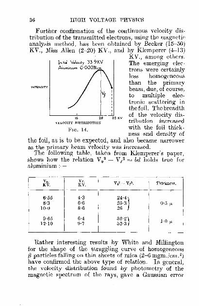
gave an inhomogeneous velocity loss. Terril, workingwith homogeneous (25-51) KV. cathode rays, penetratingrolled foils of silver, aluminium, gold, beryllium andcopper, found a continuous velocity distribution curvefor the transmitted electrons. His curve shows that thetransmitted rays contain electrons of all velocities almostup to those of the primary rays, and in addition, there isa most frequent velocity (vf) present (see Fig. 14).
Application of J. J. Thomson's absorption formulaV 0
4 - v/ = ad, held good in all his cases.
Here V o = initial primary velocity cms.jsec.,vf = most frequent transmitted velocity, i.e. the
velocity corresponding to the greatestintensity transmitted,
d = thickness of foil,a = a constant for the metal, which increases
slowly with the primary ray velocity. Foraluminium, he got the value 1·4 X 1043
C.G.S. units, agreeing with Bohr's theoretical 1·3 X 1043 , though other experimenters give somewhat different values.
The formula can, if preferred, be written V0 2 - Vf 2 = bd,where V is now the velocity in equivalent volts and bis a different constant which varies wilb the density,
since the ratio ~ was constant in all the experiments.p .
36 HIGH VOLTAGE PHYSICS
FIG. 14.
In;!;a! V.loc;!y 33 9 KVAluminium Q·Q0031cm,
INTENSITY
Further confirmation of the continuous velocity distribution of the transmitted electrons, using the magneticanalysis method, has been obtained by Becker (15-50)KV., Miss Allen (2-20) KV., and by Klemperer (4-13)
KV., among others.The emerging electrons vvere certainlyless homogeneousthan the primarybeam, due, of course,to multiple electronic scattering inthe foil. The breadth
.5 26 35 KV of the velocity dis-VELOCITY DISTRIBUTION tribution increased
vvith the foil thickness and density of
the foil, as is to be expected, and also became narroweras the primary beam velocity was increased.
The following table, taken from Klemperer's paper,shovvs hovv the relation Vo2 - V t 2 = bd holds true foraluminium :-
v•. V!.Vo' - Vi'. Thickness.KV. KV.
6·55 4·3 24'4}8·3 6·6 25·3 0·5 JJ.
10·0 8·6 26
9·65 6·4 52'2)1·0 JJ.12·10 9'7 52'3j
Rather interesting results by White and Millingtonfor the shape of the straggling curve of homogeneousf3 particles falling on thin sheets of mica (2-6 mgm.jcm. 2)
have confirmed the above type of relation. In general,the velocity distribution found by photometry of themagnetic spectrum of the rays, gave a Gaussian error

HIGH VOLTAGE ELECTRONS 37
curve ofthe form y = ~f (f3;), where f3 = vic, a = thick
ness of foil in centigrams/em. 2.
The most probable velocity loss was found to varyapproximately linearly with the thickness of micatraversed, while the thicknesses necessary for equal lossvaried as (initial velocity) 3.
Scattering. - The transmission of electron beamsthrough matter has so far been considered withoutreference to their direction of emergence.
The attractive force of the nucleus deflects the electrons away from their original path during transitthrough the atom, but generally they emerge with littlechange in velocity. On the other hand, in their encounters with electrons in the atom, the collisions nowtake place between particles of similar mass, resultingin both change of direction and velocity.
The original Rutherford atom model predicted thatthe fraction of the original beam scattered through an
e 2e 2angle greater than 6 was 7Tnt ~T; cot 2 6/2,
where n = number atoms per unit volume,t = thickness of material,
e1 = charge on the nucleus,e2 = charge on the particle,T = energy of the particle.
This prediction was well verified by Chadwick forex particle scattering by silver, gold, and copper foil.Further, he showed that the nuelear charge could begiven to an accuracy of 1 per cent. by the value of Ne,where N = atomic number and e = elementary electroncharge.
Further application by Rutherford to the case of f3-rayscattering showed, that within certain limits, the formulacould be successfully applied ;" indeed, the experimentalresults of Chadwick and Mercier, using f3-rays fromradium E, verified the single scattering law. Two important; factors have, however, to be further considered.

38 HIGH VOLTAGE PHYSICS
These are (1) change of mass with velocity of the particle,slowing it down during transit, with consequently greatertime for reaction, (2) applicability of the inverse squarelaw (assumed in deducing the formula) when the distanceof approach to the nucleus becomes comparable with thewave-length of the particle.
Thus, in the case of small angle scattering of f3-rays bylight elements, such as carbon and aluminium, Schonland's values are nearly double the theoretical values,but with heavy elements, such as gold and platinum, thecalculated and observed values agree closely.
Calculation showed, further, that the distance ofapproach to the nucleus was smaller for light elementsthan for heavy elements, being 6·5 X 10-11 ems. and2'0 X 10-10 ems. for aluminium and gold respectively.
The experimental difficulties and uncertainty as to thetype of scattering have t,o a large extent been diminishedby using high voltage cathode rays, where the intensityand homogeneity of the bundle can be varied withinwide limits. In the case of cathode rays, however, afurther consideration must be taken into account whichdoes not enter when dealing with f3-rays. This is theradiation of energy due to cathode rays in looped orspiral orbits round the nucleus, when they come within acertain critical distance of it, given by Darwin as
Ne,2-vr-=pmoc2f3
where Ne = nuclear charge, f3 = vjc.The effect of neglecting this unknown radiation of
energy term is to give experimentally increased valuesfor the amount of scattering-increases which can bequite considerable, when, as with aluminium, the cathoderay passes within three times of this critical distancefrom the nucleus. The relativity correction (1) alreadyreferred to, has been worked out by Schonland, whoshowed that the original Rutherford 'formula had to bemultiplied by a function of angle and velocity before itexplained his results. He thus gives the fraction p of

HIGH VOLTAGE ELECTRONS 39
the original beam scattered between the angles <PI and <P2 :
p = 7T/4 .nfC~t)2[cot2tIj2(<pl' f3) - cot2t2j2(<P2' f3)].
The theoretical value for p agreed to within 2 per cent.with the observed value and the relations between
(p, f), (p, N2), (p, ~2) were also found to agree with the
formula for silver, aluminium and copper up to 70 KV.Without this relativity correction, the Rutherford
formula gives a value for p which is only some 40 per cent.
of the experimental value. Incidentally, the (p, ;2)relation verifies that the inverse square law was a validassumption, at least in the cases considered. Thecurves for p and f were only partly linear-the scatteringratio increasing rapidly after a certain thickness for eachenergy of rays. This indicates the existence of pluralscattering.
Wentzel has shown theoretically that a criterion forsingle scattering is obtained if the angle of scatteringis some small multiple of the minimum deflection 3,
at a distance R = / 2 from the nucleus. The value of-V 7Tnt
2T~23 is got from cot 3/2 = N~ -.e 7Tnf
In Schonland's experiments ~ was greater than 3 for all
his foils; he thus worked under conditions giving singlescattering. Neher, in some further work on these lines,shows that Wentzel's criterion for single scattering is notsufficiently well defined, for the ratio appears to increasewith the energy of the cathode rays, being 3·3 at 45 KV.and 6·1 at 145 KV. for aluminium. He puts forward amore critical test by which single scattering may be judgedto have taken place-if the curve connecting p and <Pdoes not change shape with increasing energy of theprimary rays. Matt, in a mathematical investigation

40 HIGH VOLTAGE PHYSICS
into the scattering of fast electrons by atomic nuclei,uses the wave equation of Dirac and includes boththe effects of relativity and spin-the direction of thelatter does affect the in.tensity of scattering. The unknown effects due to radiation do not come in, since thewave-lengths dealt with are large compared with thecritical distance of approach. The magnitude of thespin term becomes comparable with that of the inversesquare law deflecting force, when the electron has anequivalent velocity of 40 KV. and over.
The fraction p of the beam scattered between the angles<PI and cP2 was
= 7TntN2e4(1 - fJ2 )p rnc4 ~4
[ cot2 T.! _ cot2 cP2 _ 2(32 log sin . cP2/22 2 sm fl/2
27T(3N(. cPl cPl' <P2 cP2) ]+ 137 sm 2 + cosec "2 - sm 2 - cosec 2" +... .This equation differs somewhat from the Schonlandmodification to Rutherford's original C{-ray scatteringequation, but the results obtained by Neher with cathoderays of 56-145 KV. energy have confirmed some of therelations which it predicts.
For instance, the relation between p and energy ofthe beam, in the case of aluminium between the angles95° 10' and 172° 5' agrees with the above formula, aswell as the dependence of p on. angle of scattering.
However, the ratio ntN2!(f/2) was not constant for all
elements as predicted on other theories, but increasedwith N as it should do on Mott's theory, but the agreement here was not good.
The greatest discrepancy between theory and experiment arises in deducing the absolute value of p. InNeher's case with aluminium it was 1·32 times Mott'stheoretical value and from 0,5-0,66 that of Schonland.The difference may possibly be due to the effects of

HIGH VOLTAGE ELECTRONS 41
secondary electrons. These in Schonland's case shouldnot be overlooked, since his stopping potentials wereonly about 200 volts, although, as previously stated,an appreciable fraction of secondary electrons withenergies up to half the primary energy are undoubtedlyliberated by surface bombardment.
Allen has shown that where multiple scattering occurs,as with small angles of scattering, the fraction scatteredwith any given velocity is a Gaussian error function
"r--_
SCATTERED
WITH
~~~~~'( ~
o~E~~~:=:::~~~~~~Angle B 25'
FIG. 15.-Multiple scattering.
of the angle of scattering, being given by the curvey = Yoe-q;2jZi.2, where cP = angle of scattering and " isa constant, which, according to classical scattering theoryvaries inversely as (electron velocity) 2.
A previous mathematical investigation by Bothe ofsmall angle (multiple) scattering showed that this typeof law agreed with the experimentally obtained directiondistribution, and, further, that the calculated values ofabsorption coefficients in aluminium for various rayenergies agreed with the experimentally obtained values.

CHAPTER IV
HIGH VOLTAGE POSITIVE IONS
Sources and Circuits.-The discovery by Kunsman,Harnwell and Barton that singly charged positive ionsof Na, K, Rb, Cs, Mg, Ca, Ba, Sr are emitted by a fusedmixture of iron oxide, and a small percentage of anyof the above elements when heated has furnished aready source for positive ion investigations. Reductionin hydrogen and thorough outgassing gave constantpositive ion currents which obeyed the usual Richardsonequation. Constant currents of 4 X 10⁻⁴ amps./cm. 2
have been obtained for 40 hours continuously, using thesystems of alkali aluminium silicates 3Li20 Al20 3 3Si02for Li ions, and 3K20 Al20 3 3Si02 for K ions. Whereprotons or gas ions of any type are required, an auxiliary discharge tube or hot cathode arc with a hole inthe cathode is used. The positive gas ion then passesthrough the hole and is further accelerated.
Any of the high voltage circuits previously describedcan be used for accelerating the positive ions, but specialcircuits have been satisfactorily developed for work muchabove 500 KV. for nuclear investigations.
The Tesla coil previously described has been used forthis work up to 3 X 10⁶ volts, but, owing to the extremely short on-time of the voltage, very intense positiveion sources are necessary for consistent results. Twocircuits in particular, those of Cockcroft and Waltonand Sloan and La'wrence respectively, have been usedwith much success in the earlier investigations on, nuclear
42

c'wt
VI C3
LT
FIG. 16.-Cockcroft andWalton circuit.
HIGH VOLTAGE POSITIVE IONS 43
structure. In the former, the transformer T chargescondenser Cg to potential E through the continuouslyevacuated high voltage thermionic rectifier VI when Tis positive. When T is negative, the condensers C2 andCg are then in series through V2 so that C2 shares partof the charge on Cg. On the next half cycle C2 sharespart of its charge with C4 through Vg, VI' and when thisprocess is repeated many times, the condensers Cl' C2,
etc., are each charged to potential E, so that a voltagenE is available, where n = number of condensers used.
To get full multiplication and a voltage fluctuationof less than 2 per cent. it is important for the rectifier emissions to be at least thirty timesthe load current, because thecharging period is only a smallfraction of the cycle.
The authors during theirwork discover'ed that plasticine covered with low vapourpressure grease made goodvacuum-tight joints.
The method originated byIsing for the multiple acceleration of ions is rather ingenious.It was developed by Sloan andLa\1>TenCe with much success.The ion energy is stepped upby making the ions passthrough a series of metalcoaxial accelerator tubes invacuo, and so arranged thatthe field is always in the same direction, as the ionpasses from tube to tube. This is achieved by connecting alternate tubes together, and applying theH.F. voltage from an oscillator to the two terminalsas shown. Currents of 10-7 amps. of singly chargedmercury ions of 1·26 X 106 volts have been obtainedin this way, using an H.F. voltage of 42 KV. at

44 HIGH VOLTAGE PHYSICS
T__T
30 metres, applied to thirty such copper tubes 5 mm.diameter, the overall length being only 114 ems. Theaccelerators are made longer and longer to allow for theincreased speed of the ion, as it passes up the system.The authors visualize the extension of the method toproduce 107-volt singly charged mercury ions, using asystem of accelerators 40 ft. long, fed by eight poweramplifiers in parallel.
I TO
(05CILLATOQ.
)
FIG. 17.-S1oan and Lawrence circuit.
Ionization.-Owing to the complex structure of thepositive ion, as compared with the electron, ionizationeffects are on the whole more difficult to interpret.That ionization by positive ions occurs above about 200volts has been established by Sutton and Mouzon,working with K+ in purified helium at pressures of1/100 - 1/10 mm. Hg. They found that argon gave thelargest number of electrons per positive ion per cm. pathper mm. pressure (6, at 800 v.). Mouzon, working withthe alkali ions in the rare gases up to 2 KV., verified theseresults. The probability of ionization P, expressed asthe product NL, where N = number of electrons liberatedper positive ion per em. path per mm. pressure, andL = kinetic theory value of the M.F.P. at 1 mm. pressure,is quite small. For example, at 500 volts, P has a valueof about 0·026 for K+ in argon. There was a definitetendency for N to reach a saturation value roughlybetween 5 and 10 in most cases at voltages in the neighbourhood of 2 KV.
Gurney, working with 7 KV. K+ ions in hydrogencould get no ionization at pressures of 1·7 X 10-3 mm.,and concludes that if it exists at all, the ionizing efficiency of the positive ion is less than 1/150 of that of50-volt electrons. This means that the M.F.P. of thepositive ions must be of the order of tens of times that

HIGH VOLTAGE POSITIVE IONS 45
of the kinetic theory value. However, some recent workby Frische, using K+ in A, Ne, He, N 2, CO, H 2 , Hg,tends to show that the efficiency of ionization by positive ions is at least comparable with that by electrons,since the maximum numbers of ions/ion/cm./mm. pressurein argon were 8'0 and 10 respectively for respectivevoltages of 4 KV. and 150 v.
The minimum voltage for ionization by K+ variedfrom 100 volts for A to 1600 volts for hydrogen, thecurves for argon and neon showing saturation at about4 KV. at 8 and 2 ions/ion/cm./mm. pressure respectively.
With lighter ions, protons and H 2+ for example,Dempster found little energy loss, and hence no deflectionor neutralization « t volt per collision) for gOO-voltions passing through helium.
Goldman, working with protons up to 4 KV., strikingH 2 or A, got no certain ionization. At higher voltages, up to 40 KV., Verwiebe got definite evidence ofionization of the residual gas by hydrogen molecular rayswhile investigating the radiations emitted by impact ona metal target. At 10-4 mm. Hg the radiation excitedhad a wave-length of ,\ 1216 AO (the first Lyman line).
Very interesting results have been obtained byRudnick on the M.F.P. for capture and loss of electrons(L1 and Lo respectively) by He+ ions of 5-21 KV. energy(approx. 0·5-1 X 10⁸ cms./sec.), passing throughhelium. He finds L1 to be about 10-4 ems. (at 760 mm.),and to be independent of the speed of the impinging ion,"lyhile Lo varied from 40 X 10-4 ems. at 5 KV. to 8·6 X 10-4
ems. at 21 KV., i.e. approximately inversely as (velocity)2.Incidentally, he found that 80-90 per cent. of the atomsin the beam are neutrals in the equilibrium state; theionizing power of the neutral He atom was very high1160 ions were formed per em. path by a neutral heliumatom of 108 cms./sec. velocity; an electron with thiswlocity producing no ionization whatever.
These results were verified and extended by Batho forXe, A, Kr ions in the same gases at 10-20 KV. A highwlocity neon atom had to make about thirty collisions

46 HIGH VOLTAGE PHYSICS
before it was ionized, while the ion required some fivecollisions before being neutralized. The numbers forargon were 60 and 5 respectively.
Secondary Emission.-Positive ions like electronsliberate secondary electrons when they impinge on ametal surface. The interaction with the surface in theformer case is, however, more complex, since simplecalculation shows that, assuming the process is the same,a hydrogen atom of 2·2 KV. would be equivalent to 11volt electrons (the minimum for secondary emission) ;actually, 900-volt hydrogen ions are sufficient. In fact,Penning found that neon ions of 7-volt energy approaching a surface give secondary emission.
As with electrons, the factors influencing the emissionare nearly the same. They are (1) nature of surface, (2)nature of impinging ion, (3) type of target.
For low voltage K+, Jackson found first evidence of.secondary emission from untreated AI, Ni, Mo at 100,150, 300 volts respectively. Cs+ was more effective andNa+ and Rb+ less effective than K+.
Proper degassing raised the voltage required by 100per cent. The emission increased linearly with the energyof the ion, and was greatest for AI, being 7 per cent. at1000 volts uncontaminated (14 per cent. contaminated).
The secondary electron velocity was small, usually lessthan 1 volt; the number of reflected positives was alsosmall, roughly some few per cent.
Extensive work on these lines by Oliphant, using He+on Mo, has verified these general observations. Theratio of secondary electrons to primary positives reacheda value of unity for normal incidence with a cold targetat 1000 volts, this ratio increasing with angle of incidence on the target. The velocity distribution curve ofthe secondary electrons obtained by the retarding fieldmethod showed that generally they had low velocitiesof 2 or 3 volts, but that some proportion existed withvelocities as high as 20 volts. This proportion increasedwith outgassed targets.
The mechanism of emission for slow rays has been

HIGH VOLTAGE POSITIVE IONS 47
explained in terms of the ionization potential Vi of theimpinging ions, and the work function r/> of the surface.Calculation shows that the field due to a positive ion ata distance of 10-7 cms. from the surface is of the order of107 volts.fcm., i.e. sufficient to extract electrons from thecold surface; these then may neutralize the slow ion,giving a system with potential energy Vi - r/>, whichmust have a positive value in order that secondaryemission may occur.
With higher velocity ions, the experiments of Baerwaldwith oxygen and hydrogen up to 20 KV. show that themaximum secondary electron velocity is about 20 volts,the bulk of the electrons having velocities of only a fewvolts, while the ratio of secondary electrons per primarypositive was about 5. These results were verified ingeneral by Schneider with protons of 23-46 KV. energystriking Al and Cu.
Absorption and Scattering.-The absorption of positiverays as with electrons takes place as the result of agradual diminution of energy by large numbers ofcollisions with electrons. Where the positive ion hassufficient energy to bring it close to the nucleus, theresult of the collision is to give a scattered distributionwhich obeys the Rutherford scattering law, as is thecase with a particles. Gerthsen, using a Geiger countersensitive to currents of 10-19_10- 21 amps., has verifiedthis for 30 KV. protons passing through celluloid filmsup to 100 p.p. thick.
Generally, with gases, small angle scattering occurs asfound by Frische with low velocity K+ in argoll, and byThomson with protons of 5-25 KV. energy. The collisionsof high voltage positive ions with gas molecules involvelittle change in direction or velocity at pressures of theorder of 10-3 mm., i.e. in those cases where little if anyionization occurs. The work of Eckard with 30-51 KV.energy hydrogen rays shows that the velocity loss onpassage through thin celluloid films (20-340 fLfL) variedproportionally with the film thickness. The loss in,'elocity was attributed to loss of charge, neutralization

48 HIGH VOLTAGE PHYSICS
and scattering, and appeared to be independent of thevelocity of the rays. This is somewhat surprising,since the work of Baerwald with 19-46 KY. rays showedthat, assuming the velocity loss was due to ionization,the number of ion-pairs produced per positive ion perem. per mm. pressure in air, increased linearly with velocity from about 20-30, and the same sort of law wouldbe expected to occur with thin solid films. Further,Eckard finds that the energy loss increased with increasing velocity of the particle, unlike the case of rJ.
particles where the ionization was a maximum towardsthe end of the range, i.e. for lower velocities. Gerthsenconsiders that this type of velocity loss must have a lawfor the range R given by R = kvx, where x is < 2.In fact, the law R = kv 1'5 was found to express hisresults for the passage of protons through air and hydrogen. The interpretation of results for positive ion transmission through matter is somewhat difficult, owing tothe complex changes such as transfer of charge andenergy, etc., which the positive ion may undergo oncollision. Thus, Gerthsen shows that He+ is to a largeextent transformed into He++ on passage through matter,when it has a velocity equivalent to about 100 KY.
Theoretically this figure can be verified, assuming asimple collision process to occur.
Nuclear Bombardment.-High-speed bombardment ofatomic nuclei, using protons and molecular hydrogenrays, has given interesting clues as to their structure.All previous results in this direction had been obtainedwith rJ. particles having energies of the order of fivemillion electron volts. The substitution of a source ofprotons easily controlled both as regards speed (up to2-3 million volts) and intensity, and free from objectionable y-ray effects, has certainly been a big improvement,which is likely to lead to far-reaching results.
A further advantage of using protons is that onGamow's theory of artificial disintegration, they havea greater probability of penetrating the nucleus thanrJ. particles of equal energy.

HIGH VOLTAGE POSITIVE IONS 49
400500
FIG. 18.
o'--....,.;=---'---'--'---~100 200 300
kV
IbOO
zooo
4000
~1200"-.:
c 800
~-i. 400
Cockcroft and Walton in their earliest experimentsused a mixture of protons and hydrogen molecular raysaccelerated through 300 KV. and bombarding targetsof lead and beryllium (probability in the latter casewas 6·2 X 10-3). They obtained a non-homogeneousradiation, emitted at 280 KV., but its intensity was veryweak, being only of the order of Tottoo of that producedby an equal electron source. Previous work by Barton,with electrons and protons of up to 25 KV. energy strikinga copper target, had sho'wn that no detectable X-radiationwas produced by proton currents of 10 - 9 amps., whereasdetectable X-radiationwas produced by elec-tron currents of 10-14
amps., the X-ray efficiency of electrons beingsome thousand timesthat of protons.
Extension of the workof Cockcroft and Walton to over 700 KV.with currents of 1 /LAand upwards, impinging at 45° on a lithiumtarget, gave rx particlesliberated from the lithium nuclei by the proton bombardment.These produced bright scintillations on a zinc sulphidescreen, and had a range in air of 8·4 ems., which did notappreciably change with increased voltage. Their curveshows the number of disintegrations per minute per /-LAat various accelerating voltages and indicates one disintegration per 109 protons at 250 KV. ; this increasesto 10 at 500 KV.
The kinetics of the disintegration process have undergone some fundamental changes since the discovery ofthe neutron by Chadwick. The neutron is supposed toconsist of a proton and electron tightly bound together
4

50 HIGH VOLTAGE PHYSICS
as a single unit, having a mass approximately equal tothat of the proton, but with no net charge. Evidenceof its presence was afforded by the radiation emittedby I/.-ray bombardment of boron, as it was equivalentto 10 X 106 electron volts, i.e. greater than any knowny-radiation. Further, the observations of Curie andJoliot that these radiations from Be and B could liberateprotons from substances containing hydrogen, with avelocity of 3 X 10⁹ cms.jsec., necessitated a quantum of50 X 106 volts if considered in the light of the Comptoneffect. This had to come from the interaction of the Benucleus with an I/. particle of 5 X 10⁶ volt energy. Thiswas obviously a difficulty which was removed by assumingthat the radiation consisted of neutrons. The liberatedprotons had a maximum range of over 40 cms. in air,with a maximum velocity of 3·3 X 109 ems./sec., whichis equivalent to an energy of 5·7 X 106 volts. This isthe energy with which neutrons are liberated from Beby I/.-ray bombardment, so that the reaction representedas follows consists in a transfer of energy from theneutron. to the nucleus, which, for the case where hydrogen is present, gives the protons (recoil atoms) allvelocities up to that of the incident neutrons:
I/. particle [--+ Neutron --+ 1--+ Proton (recoil atoms)(N) (P)
Be or B. Hydrogen.The I/. particle of course consists of (2P + 2N).
The disintegration of aluminium results in captureof the ct. particle as follows:-
I/. + (61/., IP, 2N) --+ (71/., 2N) + PAluminium. Recoil High-speed
Silicon. proton.With boron, capture of the I/. particle takes place asfollows :-
I/. + (21/., IP, 2N) --+ (31/., IP, IN) + NBoron. Nitrogen recoil.
In Cockcroft and Walton's experiments,(lex, IP, 2N) + P --+ 2ex.
Lithium.

HIGH VOLTAGE POSITIVE IONS 51
Calculation from mass defect in the disintegration processagrees \yith the observed range of the ()(, particles. Ex·tension to other elements has shown similar effects, theactual number of disintegrations obtained being in thefollowing order: Li, B, F, C, AI, Ca, Co, Ni, Cu, Ag, Pb, V.
The most outstanding difficulty in connection withnuclear disintegrations appears to be the fact that suchdisintegrations were observed with elements of highatomic number, although, theoretically, this should notoccur for these comparatively low energy particles.
An explanation might, however, be advanced onthe lines of the resonance disintegration produced by()(, particles as put forward by Pose and Hafstad. Theyenvisaged disintegration protons produced by such aprocess; however, the matter is still unsettled. Theexperimental results on the nuclear disintegration oflithium obtained by Cockcroft and Walton were con·firmed by Lawrence, Livingston and White and byHenderson, who worked with protons of over 106 voltenergy. The latter finds that the number of disintegrations per proton, as well as the range, vary proportionallywith the 3/2 power of the proton energy. His curve
1600
expressed in the form N = 0·0037 Ve - vV more or lessagrees with the curves by the other authors when thepresence of H 2+ is taken into account.
In the case of the disintegration of Al by protons of1·2 X 106 volts Lawrence and Livingston got a radiationwith a continuous distribution of range up to 8 cms.in air, the larger number of particles having the smallerranges, and conclude that the proton disintegrationenergy varies approximately as the atomic number.This, however, was not found to be so by White andLawrence, who got nearly the same yield of ex particlesfrom boron as from lithium above 500 KV.
Regarding bombardment by heavier particles -H2+(deutons) the experiments of Lawrence and Livingston,with currents of 3 X 10⁻⁸ amps of 1·3 X 106 v. deutons,have given extremely high neutron yields. Beryllium

52 HIGH VOLTAGE PHYSICS
liberated. 5000 recoil protons per minute, which is cquivalent to 107 neutrons per sec. The liberated protonshave a range in air of 40 cms., and the reaction mightpossibly consist in the disintegration of the deuton itself,since the proton yield varied with the neutron yield.
The most recent work of Lauritsen and Crane withdeuton currents of 10 fLA. bombarding carbon at 900 KV.,appears to show the presence of a penetrating y-radiationwith an absorption coefficient of 0·35 cm.-1 and with verylittle neutron liberation-the reaction probably takingplace as C12 + H2 -+ C13 + H' + y. Another type ofreaction which may occur in deuton bombardment is theliberation of rx. particles as shown by Oliphant, Kinseyand Rutherford. This has been verified by Lewis,Livingston and Lawrence, who utilized the deuton sourceobtained when H+H2+ of 2 X 10⁶ volt energy impingeson a target and breaks up, giving H+(660 KV.) andH 2+(1'33 X 106 v.). They bombarded nitrogen with H 2+and got rJ. particles liberated even at 600 KV., while at1·33 X 10 6 volts, 100 ex particles were liberated per 109
deutons-all apparently homogeneous and with a rangeof 6·8 cms. Similarly, Li and Be emitted rx. particles withranges of 8·2 and 3·3 cms. respectively. Further workwith C and 1·2 X 106 volt-deutons gave protons with arange of 18 cms. in air. The main point about deutonbombardment is the considerably larger number ofdisintegrations obtained as compared with protons.
Bombardment by still heavier particles He+ at 106
volts, according to Crane, Lauritsen and Soltan, producesin the case of Be an intense source of neutrons. Withthe heavy mercury ion at 2·4 X 106 v. indications of thepresence of an X-radiation was obtained by Coates, sincethe absorption in aluminium followed the exponentiallaw. There was no continuous range in wave-length, asis the case when electrons are used, nor did the wavelength vary with the energy of the beam. The wavelength emitted appeared characteristic of the K series withlight targets, while for heavy targets it was characteristicof the impinging mercury ion.
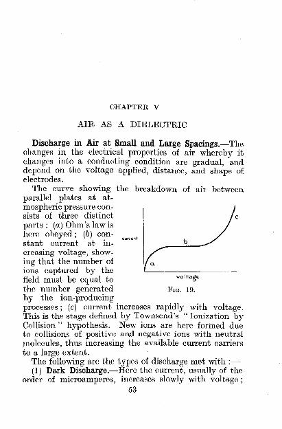
CHAPTER V
AIR AS A DIELECTRIC
c
b
FIG. 19.
a.
Discharge in Air at Small and Large Spacings.-Thechanges in the electrical properties of air whereby itchanges into a conducting condition are gradual, anddepend on the voltage applied, distance, and shape ofelectrodes.
The curve showing the breakdown of air betweenparallel plates at at-mospheric pressure consists of three distinctparts: (a) Ohm's law ishere obeyed; (b) con- curront
stant current at increasing voltage, show-ing that the number ofions captured by thefield must be equal tothe number generatedby the ion-producingprocesses; (c) current increases rapidly with voltage.This is the stage defined by Townsend's" Ionization byCollision" hypothesis. New ions are here formed dueto collisions of positive and negative ions with neutralmolecules, thus increasing the available current carriersto a large extent.
The following are the types of discharge met with ;(1) Dark Discharge.-Here the current, usually of the
order of microamperes, increases slowly with voltage;53

54 HIGH VOLTAGE PHYSICS
FIG. 20.SPACING
~ ...
~5P~R.OVER ,0 ......~~~ 0
V I LUMINOUSV 015cH.....Rc;e
I A.T E~T'R.OOl!SIIx
s
v
nothing is visible between the electrodes-the discharge isunstable, and is in its earliest stage.
(2) Glow Discharge.-Occurring at higher voltagethan (I), and characterized by a bright glow extendingthroughout the column of gas, and enveloping the electrodes; the current is of the order of milliamperes, butcan reach tens of amperes in special cases.
(3) Brush Discharge.-A form of unstable glow, consisting of irregular streamers starting at some pointand diverging outwards as a spray of blue or bluish-whitelight. It is possible to get electrical rectification by thebrush discharge, owing to the unequal mobilities ofpositive and negative (newly born) ions in the air surrounding the electrode.
(4) Spark and Arc Discharge-The air has becomean excellent conductor, and its current-carrying capacity
is limited only by the external circuit. The characteristic of the lattertype is the fall in voltageacross the electrodes withincreasing current, i.e.the characteristic has anegative slope.
When the distance between two spherical electrodes (of I in. diameter,
say) is varied, the initial discharge consists of a glowround the electrodes, the voltage required to producethis glow increasing with the spacing according to SOD.
Up to the point 0 the sparkover voltage for thesystem is practically the same as the glow voltage, butabove 0 higher voltages are required for sparkover.The spacing SX corresponding to the point 0 is knownas the critical distance for this particular arrangement,and in this case is approximately three diameters.
Goodlet, Edwards and Perry investigated such curvesfor sphere to plate gaps at distances up to over 10 ft.Their results, while confirming the above, show that both

AIR AS A DIELECTRIC 55
SX and the glow voltage increase with the electrodedimensions. At very large spacings the sparkover curvetends to coincide with that for the point plane gap, asis to be expected.
Corona.-Up to a spacing SX, sparkover takes placesimultaneously with the luminosity which first appearsat the electrodes; above this critical spacing, a distinctpale violet glow covers the electrodes, accompanied bya rather characteristic hissing noise. This is the coronapoint, and indicates the existence of an unstable form ofdischarge in the air, which is partially broken up intoozone and oxides of nitrogen in the immediate vicinityof the electrodes. Sufficient increase of voltage at thisstage again results in sparkover. Corona and consequentsparkover are only possible in non-uniform fields, i.e. forthose with a varying gradient. With corona on twoparallel wires in air, the negative wire seems studded atregular intervals with reddish beads, the intervals between the beads showing oxidation, while the positivewire is covered with a light blue glow. The formationof the beads on the negative wire appears to depend onthe nature of its surface. Polished wires always give thebeads, while corroded and enamelled ones do not. Thepresence of drops of water or oil on the surface, becauseof their high dielectric constant, cause a lowering of thecorona starting voltage, as also does enamelling of thewire. The presence of additional ions from X-ray andultra-violet sources in the immediate vicinity of theelectrodes has no direct influence on the corOI~a startingvoltage, the "natural" ions already present being sufficient. Humidity of itself has no effect except in so faras it lowers the air density, and if so, must be allowed for,as shown later. Peek found no special effects due to frequency up to 20,000 cycles, but at very high frequenciesthe starting voltage for corona was somewhat lowered.
With parallel wires in air the gradient gw at thesurface required for corona formation appears to beindependent of the spacing S, where this is large comparedwith the wire radius r cms.

56 HIGH VOLTAGE PHYSICS
(0'301) .Peek gives gw = 30 1 + vi KV./cm. maXImum.
The gradient gw can also be defined in terms of the voltageV between the wires and their dimensions as
Vgw=---S'
r loge -r
Thus, as r decreases, gw increases, and may reach avalue of several hundred KV./cm. for very thin wiresbefore corona can form on them. With two brass rods1 in. diameter, spaced 2 ft. apart, corona will first appear
(0·301 )when gw = 30 1 + ./- KV./cm. = 38 KV./cm.v 1·27
The gradient is greatest at the wire surface, and fallsoff as the distance from the surface increases. Peek hasshown that the gradient at a distance 0·301vi from thewire surface is always constant at 30 KV./cm. for allradii. The ionic processes which culminate in corona orpartial breakdown of the air, hence must take placewithin this distance. It thus appears that in order toobtain corona, initial gradients in excess of 30 KV./cm.at the wire surface are necessary. This value definesthe " electric strength " of the air.
A very common electrode system met with in practiceis the coaxial cylinder arrangement. With a thin wireradius r as the inner cylinder Peek gives the coronagradient
. ( 0'308)gw = 31 1 + vr- KV./cm. max.
when r = 0·01 em.; gw = 125 KV./cm. max.The gradient appears to depend only on the radius of
the inner cylinder, and to be independent of that of theouter cylinder.
Booth investigated the field distribution for thebalanced field of this system by inserting a small insulated spherical probe into the field, and taking potential

AIR AS A DIELECTRIC 57
3·5
o L __--.:::::::~;:;::;
KVFIG. 21.
measurements with delicate electrostatic voltmeters ofsmall capacity.
His curves (Fig. 21) for a 20 Band S wire in a 3t em.radius cylinder show-
(1) within the first t em. from the wire, and whetherpositive or negative, there is a steep fall ofpotential by over half the total value;
(2) the potential fall soon after becomes nearly constantto within a small distance from the mouthof the cylinder-the electric force within thisregion thus vanishes;
(3) there is an abrupt potential fall over a small distance near the mouth of the cylinder.
The forms of curve for the corona glow, whetherwell developed or barely perceptible, remain the same.Such curves, if taken all theway up to sparkover and atvarious pressures, should beof value in helping to elucidate some aspects of sparkoverin non-uniform fields.
It was pointed out in connection with the use of thesphere gap as a measuringinstrument that, for reliableresults, the separation of thespheres should not be greaterthan their radius. The reasonfor this is that when thespacing is a multiple of the radius (> 3), the coronawhich then forms leads to inaccurate results. For coronato form on spheres Peek has shown that the necessarygradient at the surface is given by
2"' 2(1 I 0'54) KV /{Is = ,. T Vr . em. max.
A eurve plotted out for values of {Is and r shows that whenr is about 5 ems. and above, {Is becomes sensibly constant
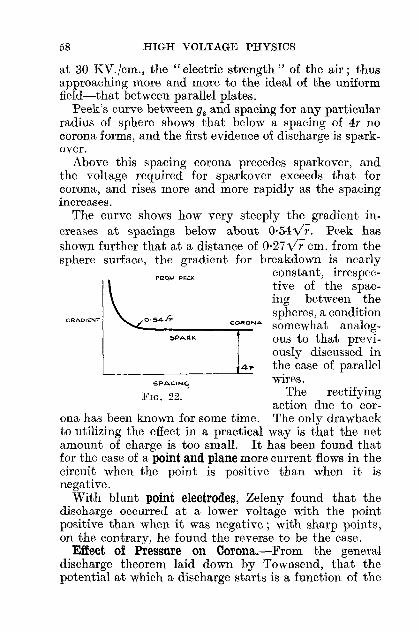
58 HIGH VOLTAGE PHYSICS
FIG. 22.
CRADIENT
at 30 KV./cm., the" electric strength" of the air; thusapproaching more and more to the ideal of the uniformfield-that between parallel plates.
Peek's curve between gs and spacing for any particularradius of sphere shows that below a spacing of 4r nocorona forms, and the first evidence of discharge is sparkover.
Above this spacing corona precedes sparkover, andthe voltage required for sparkover exceeds that forcorona, and rises more and more rapidly as the spacingincreases.
The curve shows how very steeply the gradient increases at spacings below about O·MY;' Peek hasshown further that at a distance of 0·27yr em. from thesphere surface, the gradient for breakdown is nearly
F~QM .EOK constant, irrespective of the spacing between the
0-545 spheres, a condition________"_O...R_QNA somewhat analog-
ous to that previously discussed in
4,.. the case of parallelL-- .L-- wires.
SPACIN~
The rectifyingaction due to cor
ona has been known for some time. The only drawbackto utilizing the effect in a practical way is that the netamount of charge is too small. It has been found thatfor the case of a point and plane more current flows in thecircuit when the point is positive than when it isnegative.
With blunt point electrodes, Zeleny found that thedischarge occurred at a lower voltage with the pointpositive than when it was negative; with sharp points,on the contrary, he found the reverse to be the case.
Effect of Pressure on Corona.-From the generaldischarge theorem laid down by Townsend, that thepotential at which a discharge starts is a function of the

AIR AS A DIELECTRIC 59
density of the gas, and the linear dimensions of the electrode system, it can be inferred that the corona gradientmust likewise be some function of these quantities-infact, it can be shown that the corona gradient is directlyproportional to the density of the gas, other thingsremaining the same. Peek shows that in the case of awire and concentric cylinder, the gradient at the wire
(0'308)= 31p 1 + Vpr KV./cm. max., where p = pressure
of gas (air); r = radius of wire. This equation has beenfound to hold down to pressures of a few cms. of Hg.
F h -?~·2 (1 0'54) KV I dor sp eres, gs-~I p + VPf .,cm.max., an
for parallel wires, gw = 30p(1 + O~~~) KV./cm. max.
In the latter case a higher voltage is required to producenegative corona than that for positive corona for allpressures dovill to 1 mm. Hg; below this pressure thereverse is the case.
The effects of temperature (t) must be taken intoaccount by the corresponding change in density which it
produces, the density (d) being given by 2;~9~ t; hence,
in each of the above formulre for the gradient, it will benecessary to substitute this factor for the pressure p,whenever both pressure and temperature have to betaken into account. When the pressure falls belowabout 1 mm. Hg, the above laws no longer hold. Themolecular mean free paths now become comparablewith the dimensions of the apparatus, and other factorshitherto neglected or considered unimportant at thehigher pressures must be further considered. Meserveyhas investigated such effects for air from pressures of1 mm. Hg and lower in the case of the concentric cylinderarrangement. .
He finds that for any particular pressure, corona formsat a lower voltage with the inner cylinder negative thanwhen positive, and, further, that there seems to be some

60 HIGH VOLTAGE PHYSICS
FIG. 23.k V aCl"'OSS condQ.ns~,.
Ouhu d'am 127" }lc.ngt-h 70"!r\n41" (wIn) I mm
"
,,~ J<3 r
o'Il-c~:--"::-~~--=--::'20 30 40 50 80 QO
i 2-0
e
particular pressure, different for each type, at whichthe corona voltage is a minimum.
At still lower pressures negative corona as such nolonger appears, although positive corona can still bedetected. This soon gives way to a type of vacuumdischarge when the voltage is sufficiently increased.
Current in Corona Discharge.-In designing highvoltage apparatus, the electrodes and spacings mustbe so dimensioned that gradients above the criticalcorona gradient are not exceeded (except for some veryspecial and unique cases), otherwise there will be a loss
CONCENTO« cYu...e'o, of power and efficiencydue to the corona currents which flow through
Corona obs<rv.d .1 'ppro. 30 kV the intervening air.AC Sparkovu 107 kV These currents can be
quite appreciable-certainly tens of milliamperes per metrelength, at several hundred KV. with a correspondingly heavy powerloss. In laboratory workthe wire and concentriccylinder arrangementconstitutes a usefulsource of leakage currentwhose limits can be
easily controlled by altering the diameter of the wire.The curve shown by the author was taken for such asystem on D.C.; the calculated corona voltage agreeingwith the visual observed voltage (in the dark).
The corona current i in such a system is given by
i = kV(V - V e),
where V = applied voltage,Ve = voltage at which corona appears,
k = a constant depending on the radius R of the
external cylinder and approximately oc ~3'

AIR AS A DIELECTRIC 61
The power loss in this case is given by
iV = kV2(V - Vc).
Tmvnsend gives i, the current per unit length for positiveV(V - V c) .2k1 h k b'l' f .corona, = R' were 1 = mo I lty 0 POSI-
R2 log - tive ion.r
This formula, when applied to the experimental casecited above, gave values of current of the right orderof magnitude.
Peek has investigated at great length the variationof power loss with voltage on parallel transmission linesand has experimentally verified the quadratic form of theloss curve at the higher voltages.
Sparkover.-Sparkover, or complete temporary breakdown of the air between the electrodes, will occur whenthe gradient is sufficiently increased to cause local breakdown. This soon spreads throughout the whole of theinter-electrode space and gives the required number ofions to carry the current-which can be tens of amperes.Simultaneously with this sudden increase in current,there is a corresponding fall in voltage across the electrodes to a very low value, the slope of the characteristicnow being negative. The processes which lead up to aspark in air had for a long time seemed obscured owingto the experimental difficulties involved. The fact thatthe spark lag, i.e. the time it takes for spark conditionsto "build up," was of the order of 10-8 sees. led to theapplication of the high-speed cathode ray oscillograph byRogowski for recording the potential variations thatoccur across a gap.
In addition to this, the detailed examination of theKerr cell by Beams, and the experiments carried outwith its aid by Lawrence and Dunnington, have helpedconsiderably in unfolding the nature of an air spark.The Kerr cell consists of two copper plates immersedin carbon bisulphide. When a potential difference isapplied to the plates the carbon bisulphide acquiresthe property of becoming doubly refracting, i.e. the

62 HIGH VOLTAGE PHYSICS
light it passes is polarized: this property disappears a8soon as the voltage across the plates is removed.
The cell is placed between crossed Nicol prisms, hencethe combination will pass light only if voltage is impressedacross the cell. This" 'shutter " will thus be open for theperiod for which the voltage lasts across the cell.
In Lawrence and Dunnington's arrangement the cellis open during the initial stages, during which the voltageis rising across the gap. As soon as the gap sparks over,the light from the gap is passed by the cell for such a timeas the voltage wave takes to collapse, i.e. is determinedby the length of wire from gap to cell divided by thevelocity of light. By altering the length of wiring to
vAOI..>..el.E LENCTl-1S OF LEAO TO CELL
FIG. 24.
the cell, the time for which the cell is open can be automatically altered up to 50 X 10-8 sees. (Fig. 24).
In its very early stages the spectrum of the dischargeconsists of air lines with no metallic lines whatsoever.As the discharge develops, the lines of the metal of thegap begin to appear, but are broadened due to the Starkeffect. Calculations from the observed broadening indicated inter-ionic fields of average value of 106 volts/em.at this stage. The average velocity of migration of themetallic ions during the first 27(10-8 ) sees. was foundto be 2·5 X 105 cms./sec. The discharge, as revealedby the photographs, takes the form of a thin streamer,narrow at the anode and gradually broadening to aboutfour times the anode area of order (10-4) ems. 2, on reaching

AIR AS A DIELECTRIC 63
the cathode, the current density being of the order106 amps.jcm. 2 (Fig. 25).
Further inferences showed that about one-third of themolecules in the discharge path had been ionized.Such intense ionization was accounted for on Saha'sthermal ionization theory, a temperature in the region of10,000° K. being necessary for a satisfactory explanation.
The nature of the electrode surface in sparkover testsis rather important. Large surface discontinuities, producing local discharges, give potentials of too low avalue; the same effect has been recorded by Peek forsurfaces contaminated by oil, moisture or dirt. Theextensive tests carried out by the E.R.A. on spheresof brass, phosphor bronze and mild steel showed thatpolishing with "metal polish" on cotton wool andfinishing with chamois leather gave consistent results.Microscopic examination of the surface revealed scratches,
+ C:::::---=:J-FIG. 25.
which probably helped to keep the sparkover voltageregular and are thus desirable. Further polishing witha rotating buff gave even more consistent results. Withhigh frequency, the surfaces must be well polished foraccurate work; local irregularities on the surface givingreduced sparkover voltage, due to brush discharge.
The work of Whitehead and Castellain has shown thatfor 20 mm. spheres, humidity (75 per cent. in clean air)causes a slight decrease in sparkover voltage. On theother hand, in the case of the needle gap, the reverseholds true-a definite increase in sparkover voltage occurswith increase in humidity.
Paschen's Law.-In the case of uniform fields in airand other gases, Paschen's Law can be briefly stated asfollows: the sparking potential is proportional to theproduct of spark length (l) and gas pressure (p), i.e.proportional to the mass of gas or number of molecules

64 HIGH VOLTAGE PHYSICS
FIG. 26.
KV100
between the electrodes. This has been experimentallyconfirmed for values of]J (mm.) X 1(ems.) up to 20,000 inair, i.e. for sparking distances of about 30 ems. at S.T.P.When this product falls below about 1, the law no longerholds, the slope of the curve now being in the oppositedirection. Thus, for any fixed spark length there is acritical pressure for which the sparking potential is aminimum (Fig. 26).
With spherical electrodes in air at short spacings,Hayashi found the sparking potential to increaselinearly with pressure up to about 10 atmospheres.Above this the curve slowly flattens out. He also
found that for shortspark lengths (t-Itmm.) at 10 atmospheres and above,the sparking potentialis not proportional tothe spark length forany particular pressure.
Peek, working withshort needle points in
/0,000 r-xt air (up to i-in.) finds(I" mm. tcms) the sparking voltage
approximately proportional to pressure
up to 14 atmospheres. Above this, there is a decidedfall in voltage, and little further rise takes place up to100 atmospheres.
Sparking: Electrode Systems.-With point and planeresults are somewhat erratic, because sparkover voltagedepends on "sharpness" of the point. The sparkoveris usually preceded by the dark discharge and corona.With care a linear calibration more reliable at the largerspacings and having a slope of about 5 KV. max.jcm. isobtained: this figure is helpful in estimating sparkingdistances in H.T. circuits. It is interesting to note thatat ordinary pressures in air the sparkover voltage with

AIR AS A DIELECTRIC 65
the point positive can be less than half that when the pointis negative: this effect tends to reverse with decreasedpressure.
Reliability with the needle gap (No. 00 sewing needles)is limited to the region 10-30 KV. Below or above theserespective values humidity effects, incipient brushing,etc., tend to put the calibration out. Above 30 KV.the slope is about 4·2 KV. max./cm.
When used on continuous high frequency, the needlesas well as the air gap become quite hot, and the sparkover voltage readings are too low. On the other hand,with impulses, the reverse is true, the gap readingsindicating too high a voltage.
For measuring high-frequency voltages, as well assteep wave-front impulses, the sphere gap is very re-liable. Within the spacing O'54vr to 2r, the gradient ispractically constant, and the ideal uniform field isapproached; the sparkover voltage is then a linearfunction of the spacing and the system is calibrated forthis region.
Above spacings of 2r the gradient increases, and atspacings of 4r and upwards corona appears, the sparkover voltage now increasing more rapidly than thecorona voltage.
The ratio of outer and inner cylinders in the concentriccylinder arrangement determines whether or not thefirst sign of discharge is a spark. If this ratio is > 2'78,corona will first form and the sparking voltage will bemuch greater than the corona voltage. If the ratio is< 2'78, no corona will form on the inner cylinder, andthe breakdown voltage is the sparkover voltage.
Peek explains the sparkover by assuming a partialbreakdown which starts as a corona at the inner surface,and extends to a distance 0·3 vr from that surface, towhere the gradient falls below go(30 KV./cm. in air).When this critical distance is comparable with thedistance between the cylinders, complete sparkover willtake place.
5
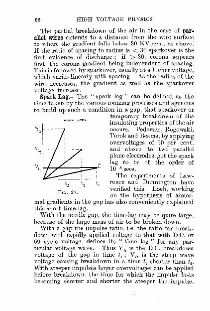
66 HIGH VOLTAGE PHYSICS
FoR,OM pE,EK
~3
FIG. 27.
The partial breakdown of the air in the case of parallel wires extends to a distance from the wire surfaceto where the gradient falls below 30 KV./cm., as above.If the ratio of spacing to radius is < 30 sparkover is thefirst evidence of discharge; if > 30, corona appearsfirst, the corona gradient being independent of spacing.This is followed by sparkover, usually at a higher voltage,which varies linearly with spacing. As the radius of thewire decreases, the gradient as well as the sparkovervoltage increase.
Spark Lag.-The "spark lag" can be defined as thetime taken by the various ionizing processes and agenciesto build up such a condition in a gap, that sparkover or
temporary breakdown of theinsulating properties of the airoccurs. Pedersen, Rogowski,Torok and Beams, by applyingovervoltages of 50 per cent.and above to two parallelplane electrodes, got the spark
C lag to be of the order ofVt , f.-I......,""-I--~-::::::OO,! 10-8 sees.
The experiments of Lawrence and Dunnington haveverified this. Loeb, workingon the hypothesis of abnor
mal gradients in the gap has also conveniently explainedthis short time-lag.
With the needle gap, the time-lag may be quite large,because of the large mass of air to be broken down.
With a gap the impulse ratio, i.e. the ratio for breakdown with rapidly applied voltage to that with D.C. or60 cycle voltage, defines its "time lag" for any particular voltage wave. Thus ViI is the D.C. breakdownVOltage of the gap in time t1 ; Vt, is the steep wavevoltage causing breakdown in a time t2 shorter than t~.
With steeper impulses larger overvoltages can be appliedbefore breakdown, the time for which the impulse lastsbecoming shorter and shorter the steeper the impulse.
AIR AS A DIELECTRIC 67
With the sphere gap the impulse ratio is practicallyunity (as it is with all uniform fields), even with steepwaves which reach their crest values in 1/10 microsecond.
With the needle gap impulse ratios as high as 3·5 havebeen recorded. In this connection it is interesting tomention that Peek used in his experiments a 5 millionvolt generator capable of giving waves of from a fewmicroseconds to over 1000 microseconds in duration, thesparkover distance with the latter being 28 feet.
Investigation of factors which influence the "timelag" has revealed the importance and effects on the gapof external ionizing radiations. It has been known fora long time that these help to give consistent resultswith a sphere gap.
Whitehead and Castellain found a small tendency tolower sparking voltages with their 62·5 mm. spheres whenirradiated with ultra-violet light. This has been verifiedwith the three-point gap, a device in which the maingap between two points is influenced by an auxiliarydischarge to the third point. With this arrangement,the "time-lag" of the main gap is more or less eliminated by the radiations of wave-length 13-1000 A., whichproceed from this auxiliary gap; this is the only factorwhich is necessary to give the desired effect; subsidiaryeffects due to the auxiliary gap, though helpful, are notessential.

CHAPTER VI
SOLIDS AND LIQUIDS AS DIELECTRICS
ON the classical electro-magnetic theory propounded byMaxwell, all dielectric behaviour could be explained interms of the two characteristic properties of a dielectric-its specific inductive capacity K and its electricalconductivity p, the total displacement in a dielectric
under electrical stress being P = 4K
. ~ e.m.u.,7T v
where F = field,v = velocity of light,P = polarization or dielectric strain.
The larger K, the greater the electric displacement, thelatter being directly proportional to, and in the directionof the field. This displacement is only momentary andwhen the field is removed, the displaced electrons canreturn to their original position, giving a displacementnow in the reverse direction. These are the familiarcharge and discharge currents of a condenser.
Superposed on this displacement current is the normalconduction current through the dielectric, obeying Ohm'sLaw, and depending on the insulation resistance. Thisleakage current starts at a comparatively large valueand decreases with time to a fairly constant value,owing to the building up within the dielectric of spacecharges, which sometimes alter the field quite considerably.
Abnormal Properties of Dielectrics.-The dielectricphenomena of absorption of charge and power loss in
68

SOLIDS AND LIQUIDS AS DIELECTRICS 69
alternating fields are known as anomalous properties,since these should be non-existen.t for perfect dielectrics.
The absorption. curren.t which is superposed on thenormal displacement and conduction currents is at firstlarge and then decreases over a period of several hours,to zero, the total current being then the conductioncurrent. This absorption of charge is completely reversible only in the case of solids; the resulting quantityof electricity, in abnormal discharge, is, according tothe Hopkinson Superposition Principle, equal to thatfor abnormal charge. The detailed work of Wagnershowed that the abnormal charging current varied duringshort time intervals according to the law I a = Bt-m ,
where m is a constant < I. In the case of an idealdielectric, the current leads the voltage by 90°, but inpractice this angle is diminished by a small angle ct.,which varies from dielectric to dielectric, and even withthe same dielectric may vary with its past history.The power factor of the dielectric is given by sin ct.,and the total power loss is expressed as IV sin ct., whereI and V are R.M.S. values. It is clear that a dielectricwith a high power factor will dissipate appreciableamounts of energy which will impair its electricalqualities.
Conduction in Solid Dielectrics.-The experiments ofWarburg on the conductivity of glass, showed that thesodium ion carried the current from the positive electrodethrough the glass to the negative electrode. After sometime, a negative space charge built up in a small andnot clearly defined region round the positive electrode.As no more sodium ions were available the conductivitydecreased, its rate of decrease depending on the timerate of formation of space charge. To get an accuratevalue for the conductivity, it is necessary to find itsvalue before space charge builds up, or, to preventelectrode polarization, either by supplying the deficiencyof the positive ion by external means, or by workingwith A.C.
Robinson has given some interesting curves for the
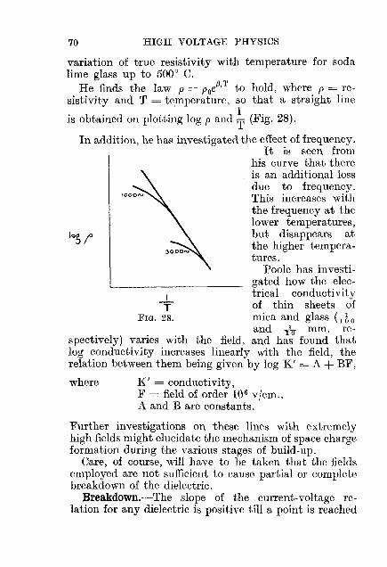
70 HIGH VOLTAGE PHYSICS
IT
FIG. 28.
'0; !'
variation of true resistivity with temperature for sodalime glass up to 5000 C.
He finds the law p = PoilT to hold, where p = resistivity and T = temperature, so that a straight line
is obtained on plotting log p and ~ (Fig. 28).
In addition, he has investigated the effect of frequency.It is seen from
his curve that thereis an additional lossdue to frequency.This increases withthe frequency at thelower temperatures,but disappears atthe higher temperatures.
Poole has investigated how the electrical conductivityof thin sheets ofmica and glass (rhand rIo mm. re
spectively) varies with the field, and has found thatlog conductivity increases linearly with the field, therelation between them being given by log K' = A + BF,
where K' = conductivity,F = field of order 106 v/cm.,A and B are constants.
Further investigations on these lines with extremelyhigh fields might elucidate the mechanism of space chargeformation during the various stages of build-up.
Care, of course, will have to be taken that the fieldsemployed are not sufficient to cause partial or completebreakdown of the dielectric.
Breakdown.-The slope of the current-voltage relation for any dielectric is positive till a point is reached

SOLIDS AND LIQUIDS AS DIELECTRICS 71
on the characteristic at which the slope becomes negativeand the current becomes unstable. This point determines the dielectric strength (voltage) of the insulation.This voltage is not constant even for the same batchof insulation, but depends on its past history. Alsoit is lower, the larger the electrode area, owing to thegreater chance of weak spots. The breakdown usuallytakes the form of a puncture accompanied by charring,splintering or volatilization depending on the power shortcircuited. There is little doubt that thermal effects in thedielectric tend to precipitate breakdown conditions, sincethe conductivity rises steeply with temperature. The relation between breakdown voltage (B.D.V.) and thickness tof insulation is generally of the form B.D.V. = kt + p,where k and p are constants. For thin sheets of materialB.D.V. ex. Vr which holds up to t mm. for glass and upto 5 mm. for porcelain. For thicker sheets the curveflattens out, hence maximum strength is obtained withthin sheets. The very recent work of Jost indicatesthat for thin tantalum oxide films the dielectric strengthvaries directly with the thickness for films from 24250 mfk, the breakdown strength being in the neighbourhood of 2 X 10⁶ volts/em., a gradient sufficient forliberating" field currents."
Some recent experiments of Terada, Hirato andYamamoto are interesting in connection with surfacebreakdown. These authors examined the tracks produced by condenser discharge sparks along window glass.They obtained fine hair cracks about 3-5 fk deep, extending along the whole spark track and transverse tothe direction of the spark. The breadth of the crackzone was proportional to the quantity of charge available,so that local surface heating effects increase the alreadyexisting strain in the surface layer.
Breakdown: Effect of Temperature.-Generally, increase of temperature decreases B.D.V. of all solids. Aporcelain insulator, good for 70 KV. at 30° C., will breakdown at 20 KV. at 180° C. In this connection, fourfactors have to be considered: (1) structure of the material,

72 HIGH VOLTAGE PHYSICS
(2) temperature gradient in and out of the insulation,(3) superimposed heating effects of the conduction cur·rent, (4) heating effects are cumulative.
The theory of thermal instability based on (4) wasfirst put forward by Walker and expanded by Wagner,who assumed a heterogeneous dielectric. Dreyfus, onthe other hand, assumed a homogeneous dielectric whichwas electrically stable if its internal temperature didnot exceed some particular value. Further deduction
~thickness .
showed that B.D.Y. ex f( t t)' prOVIdedmean empera urethere was no temperature gradient through the dielectric:if the latter did not hold, then B.D.Y. varied inversely as
vif(mean temperature).
For some materials, e.g. glass, there appears to be adefinite low range of temperature which has no influenceon the B.D.Y., which is then defined by the peak voltage:where heating effects occur, the R.M.S. value definesthe B.D.Y. Exceptions to the general rule, however,occur, as with wet or dry pressboard, where B.D.Y.increases with temperature due to complex structuralmodifications not yet understood.
Breakdown: Power Loss and Frequency.-The powerloss in any dielectric, given by IoYo sin a, can be lookedupon as being dissipated in a resistance either in parallel(r p) or in series (rs) with the ideal loss-free dielectric.If I o and Yo are the R.M.S. current and voltage, the
equivalent parallel capacity is Cp = yIo . cos a, while theoW
'It' "C I o 1 heqUlva en serIes capacIty IS s = -Y . --, wereoW cos a
W= 21Tf. The power factor sin a' . tan a = -C1
= rsCsw,rp pW
hen.ce the power loss = Y02wkCo tan a, where k = dielectric con.stant and Co = equivalent capacity for anair condenser. The power loss thus (1) ex Y2 and (2) exf.Peek's experiments on. varnished cloth verified (1) for

SOLIDS AND LIQUIDS AS DIELECTRICS 73
gradients of 12 KV./mm., while Fleming and Dyke andAddenbrooke verified (2) at moderate frequencies.
At very high frequencies an additional factor oc j2enters, the power loss is oc! up to 500 k.c. and then falls(for crown glass), the maximum powerfactornot occurringat the same time as maximum power loss. Accurateknowledge of power factor indicates the quality andbehaviour before and during life, and also the safe highvoltage limit of the dielectric. Its low range of values(0,001-0,2) necessitates an accuracy of 1 in 10,000 in itsmeasurement. This has been achieved by carefulmeasurement, using delicate wattmeters; the high
Crown.GI••• (Baorsto P.R5. 91>.303. '9~
FIG. 29. FIG. 30.
voltage (up to 20 KV.), electrostatic type has beendescribed by Rayner, Standring, Davis and Bowdler.The use of the oscillograph, giving the wave-form ofcurrent and voltage as well as their phase displacement,is another ready method for obtaining power loss andpower factor. The Schering bridge shown gives goodresults, and is a null method. 0 1 is a standard condenserof known power factor, and the bridge is balanced byvarying R 3 and 04' Earth shields eliminate stray capacityeffects. The power factor and power loss is then determined in terms of 0 4 and R 3 •
By finding when the power factor no longer changeswith time at every impressed voltage, the maximum
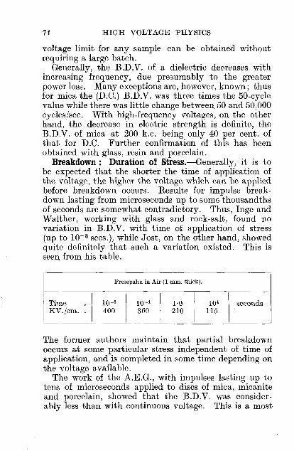
74 HIGH VOLTAGE PHYSICS
voltage limit for any sample can be obtained withoutrequiring a large batch.
Generally, the B.D.V. of a dielectric decreases withincreasing frequency, due presumably to the greaterpower loss. Many exceptions are, however, known; thusfor mica the (D.C.) B.D.V. was three times the 50-cyclevalue while there was little change between 50 and 50,000cycles/sec. With high-frequency voltages, on the otherhand, the decrease in electric strength is definite, theB.D.V. of mica at 200 k.c. being only 40 per cent. ofthat for D.C. Further confirmation of this has beenobtained with glass, resin and porcelain.
Breakdown: Duration of Stress.-Generally, it is tobe expected that the shorter the time of application ofthe voltage, the higher the voltage which can be appliedbefore breakdown occurs. Results for impulse breakdown lasting from microseconds up to some thousandthsof seconds are somewhat contradictory. Thus, lnge andWalther, working with glass and rock-salt, found novariation in B.D.V. with time of application of stress(up to 10- 3 sees.), while Jost, on the other hand, showedquite definitely that such a variation existed. This isseen from his table.
Presspahn in Air (1 mm. thick).
Time
I
10-s
I10-'
I1·0
I10' seconds
KV./em. 400 360 210 115I
The former authors maintain that partial breakdownoccurs at some particular stress independent of time ofapplication, and is completed in some time depending onthe voltage available.
The work of the A.E.G., with impulses lasting up totens of microseconds applied to discs of mica, micaniteand porcelain, showed that the B.D.V. was considerably less than with continuous voltage. This is a most

SOLIDS AND LIQUIDS AS DIELECTRICS 75
unexpected result, as, by analogy with air, an impulseratio of some sort is expected.
For longer time intervals (minutes), Peek shows thatk
B.D.V. = B.D.V. + .41T-' where T = time, k = a con-T=oo v
stant. By plotting B.D.V. against JT' the B.D.V. at
infinite time (Too) is obtained. This gives a measure ofthe insulating strength of the material. In the case offibrous insulations, the application of an empirical lawnT = a constant, gives an indication of the life of theinsulation under some particular conditions, and hasbeen found very useful. Here, n = number of applications of brcakdown voltage, T = time of each applicationas a percentage of total time for continuous breakdown,and must be at least 40 per cent. of that time.
In practice, for testing quality, the insulation is placedbetween 10 cm. diameter discs and voltage rapidlyapplied till breakdown occurs. The" minute" test ismade by immediately placing 40 per cent. of this voltageon the specimen, and increasing the voltage by 10 percent. of the rapidly applied B.D.V. per minute tillbreakdown occurs. The" endurance" or long-time testis carried out by placing 40 per cent. of the minute testvoltage on the specimen, and raising the voltage in stepsof 10 per cent. of the rapidly applied B.D.V. at intervalsof one hour or so, till breakdown occurs. Discrepanciesin B.D.V. values, even with the same material, canusually be traced to some differences in treatment duringor after the manufacturing process.
Liquid Dielectrics: Conduction.-The process of conduction here is much the same as with solids-the initiallarge conduction current decreases with time, owing tothe formation of space charges, and also to the removalof highly conducting impurities by the field. For anoil film, Black and Nisbet find R = R o + bT, whereRo = true resistance of film in absence of space charge,b = a constant, I = final steady current for gradients of(12 volts/cm. - 600 volts/cm.).

76 HIGH VOLTAGE PHYSICS
60MINS
FIG. 31.
50r DIMETHYL oc.T ANE
I~ ':::::::-'I B v/ern
,
. -12tXIO
As with solids, an absorption effect occurs in additionwhich depends on the purity of the liquid, its temperature and the voltage gradient. This disappearswhen the voltage is removed, probably due to rapidneutralization of space charge, so that no dischargecurrent is obtained, unlike the case with solids.
The conductivity falls with time of application ofvoltage, five or six hours sometimes elapsing beforeconditions are steady. Welo's curves show a small butdistinct effect due to voltage gradient. By careful removal of all impurities normally present in hydrocarbonsand transformer oil, he has shown how the conductivity
falls with increase inpurity of the oil forall gradients up to8000 v./cm.
Finally, the workof Nikuradse andRussichurli with mineral oil has shown thatthe current-voltagecharacteristic is of thesame form as with air-above a certain volt
age, the current rises abruptly for very small increase involtage. In the saturation current region, the currentrises very rapidly with temperature, according to thelaw It = Ioe",t,where It = saturation current at temp. t,
10 = saturation current at temp. 0,
0( = temperature coefficient,
so that the log I, t curve is a straight line for any particular voltage up to their limit of 20 KV. between theelectrodes.
Liquid Dielectrics: Breakdown.-The methods employed in studying breakdown of gases have also beenapplied ~with success in the case of liquid dielectrics.Rogowski, using the cathode ray oscillograph, showedthe time of breakdown to be of the order of 10-9 sees.

SOLIDS AND LIQUIDS AS DIELECTRICS 77
(cf. breakdown of air). Photographic following throughof the breakdown, using a modified Kerr cell arrangement,has also been used with success by Washburn. Thebreakdown is slower than for air, as the impulse ratiowith oil is higher than with air, making this methodvery convenient. He was thus able to obtain photographsof both static and impulse breakdown in commerciallypure paraffin oil and xylol, in time intervals as short as0·06 X 10-8 sees. The photographs are markedly different from those for air, where there was ionization atboth electrodes. Here, however, the ionization appearsto be mostly confined to the anode region, and for longertimes (0,8 X 10⁻⁸ sees.) ; there were also cases where theionization throughout the gap was more uniformlydistributed.
The advantage in using impulses of short duration is toeliminate secondary effects and simplify the phenomena.Impulse breakdown in 0·3 X 10- 6 sees. generally showedmore uniformity throughout the gap, being the moremarked with xylol. The intense light is accounted forby the high ionization of the adsorbed gas moving to theanode, and further work with outgassed oil should proveilluminating as regards the early stages of breakdown.The importance of the removal of impurities can begauged from the fact that 1 part of water in 1000 willlower the B.D.S. from 230 KV./cm. for pure oil to about30 KV./cm. This water can be removed either by centrifuging or filtering. The dielectric strength is usuallymeasured at 60-68° F. between t-inch. diameter sphericalelectrodes, separated 0·15 in. The maximum stress isV 1·208 I •
0.15 X 2'54 volts/cm., and for good 011, at least 22 KV.
(R.M.S.) should be required across the gap for breakdown :purer oil may require as much as 80 KV./cm. (max.) beforethe gap breaks down.
If the gradient at any particular point in the fieldexceeds the safe limit, partial breakdown of the oil occurswhich corresponds with the corona effect for air. Peekhas shown that the gradient for this to occur in oil with

78 HIGH VOLTAGE PHYSICS
, '0
'00 25<", 5~. (Jiiol!,eo/ I I I
,., / I~~?5=~~ir:~no v ! I V-
t""I for~'O,"",••(,"y,'0
'b'~ /~.
" V''''' I / V1'20 I,locI'::11
20(TE,,",1~'C)
0
.o>
the concentric cylinder arrangement is
g = 36(1 + ~DKV./cm. max.,
which, in form, is similar to that for air, g depending onthe radius of the inner cylinder. Further increase ofvoltage results in sparkover which, as in air, is selfhealing. It should be stated here, that the B.D.V. isdetermined not only by the maximum value of the
voltage as for air, but inaddition, by the R.M.S.value and the shape ofthe wave. Again, unlikethe case of air for whichthere is no effect, increase of frequency tendsto increase B.D.V., although at high frequencythere is a marked de·crease in B.D.V.
Peek's curves showthe relation between the60-cycle sparkover voltage and spacing forvarious type of electrodes. They are similar
FIG. 32.-Sparkover of various to those for air, even atshaped electrodes in oil at 60,.....,. large spacings, hence the
same effects must occurduring each type of breakdown, such as space charge,movement of liquid induced by the discharge (cf. electricwind), etc.
It is common to find large variations in sparkovervoltage. Thus Goodlet, Edwards and Perry got avariation of 17 per cent. with good oil at large spacings,their scattering of results following the ordinary probability law. Peek got results much of the same kind,and showed that these variations persisted, even if theoil was changed after each sparkover: thus proving that

SOLIDS AND LIQUIDS AS DIELECTRICS 79
the effects of the sparkover were not of themselvesinfluencing the scattering of results. It i'l quite conceivable that short-time breakdown values might, bypreventing secondary effects, considerably reduce thescattering. The effect of pre-stressing the oil is generallyto reduce the value of B.D.V. as with solids. Where theelectrode system is such as to give some sort of preliminarydischarge during the pre-stressing stage, the B.D.V.appeari'! to be independent of the quality of the oil,provided that spacings above the critical value are used.
If, however, no preliminary discharges occur prior tobreakdown (at large gap spacings), the electric strengthis found to be proportional to the gap spacing. Byproper positioning of barriers of solid insulating materialin the gap, the B.D.V. can be considerably increased.Their effect is undoubtedly to limit the ion streams whichflow between the electrodes, and break up the electrolyticconducting chains, thus making the ion paths muchlonger. The work of Goodlet, Perry and Edwards alongthese lines has shown that for short-time breakdown,barriers are effective only when pre-discharge occursbefore actual breakduwn, and then only if placed incontact with the discharging electrode.
When placed in any other position in the gap, theyhave no effect. Caution must be taken in their use, asthey are liable to damage, particularly in the case of longtime discharges.
The effect of temperature is generally to decreaseB.D.V. In the case of transformer oil, however, thereis first an increase up to about 70° C., followed by adecrease above this temperature. The above authorsshow that the percentage increase may be as high as50 per cent. for the small spacings. At large spacings theincrease prevails only where pre-discharges do not occur ;if they do, the effect reverses or does not appear at all.
The effect of increase of pressure for liquids is muchthe same as for gases-increase in dielectric strength.The work of Friese indicates a B.D.V. of 90 KV./cm.per atmosphere for transformer oil with much prospectof higher values for the purer hydrocarbons.

CHAPTER VII
VACUUM AS A DIELECTRIC
PASCHEN'S Law no longer holds when the product press(mm.) X sparking distance (ems.) is less than about l.For the case of electrodes separated 1 em. apart, thiswould correspond with pressures of about 1 mm. andlower. Further, the work of Meservey shows that thecorona voltage at these low pressures can be extremelyhigh, the voltage increasing very steeply, even for smalldiminutions in pressure. The characteristic, then, of lowpressure discharges is the high voltage necessary tostart them.
This can readily be explained on the basis of theclassical kinetic theory, for the mean free path of themolecule (or ion) is inversely proportional to the pressure;thus at 10-3 mm. Hg an air molecule has a mean freepath of some tens of centimeters, and at still lowerpressures a condition of affairs exists where the molecular path is many times that of the dimensions of thedischarge vessel. The ionization by collision processwhich was necessary to account for the case of an airdischarge at atmospheric pressure, will, at these extremely low pressures, have little or no say whatever inthe conduction process. Although the molecules moveon the average tens of centimetres before meeting othermolecules, yet the number of molecules per c.c. left inthe evacuated space even at the lowest pressures ofabout 10-8 mm. Hg which can be reached with presentday vacuum technique is still of the order of 108-a
80

VACUUM AS A DIELECTRIC 81
considerable number. These, if suitably excited, arecapable of carrying hundreds of amperes across theinter-electrode space.
In comparison with other dielectrics, high vacuum isfree from leakage, at least, until gradients of the orderof 105 volts/em. or higher are reached, and does notappear to be affected by such factors as temperature,frequency, etc., which have rather marked and sometimesdrastic effects in the case of solid or liquid dielectrics.The main condition required is that the vacuum shallnot deteriorate, either by external causes, or througheffects connected with the state of the electrode system.Some idea of the "electric strength" of a vacuum ofabout 10-6 mm. Hg pressure can be gleaned from thefact that in modern extra high-tension thermionicrectifiers, a potential difference of about 250 kilovoltscan be impressed across a space of about 1 cm. betweenan outgassed cylindrical anode and a concentric filamentsystem without any breakdown of the vacuum occurring.
When the impressed gradient becomes sufficientlyhigh, of the order of 10 6 volts/cm., a new phenomenonoccurs and the high vacuum exhibits an electrical leak.This is due to the action of the field in pulling electronsout of prominences on the cold cathode; initially theseelectrons pass along the lines of force to the anode andconstitute what are now known as the" Field or Autoelectronic Currents." All high vacuum effects are boundup with the presence of these field currents which willbe fully discussed later.
It is interesting to point out in connection with thesehigh gradients, that even in air at atmospheric pressure, itis possible for the gradient to be as high as 10 6 v./cm.without breakdown occurring in uniform fields acrossminute air gaps of about 10-4 em. The experimentsof Broxon on these lines show definitely that with a gap of2£ wave-lengths (0,546 JL green line from mercury) Ohm'sLaw holds, and that gradients of over 1/2 . 106 v./cm.do not produce breakdown of the gap, although Woodhad previously suggested that these high gradients
6

82 HIGH VOLTAGE PHYSICS
produce "field current electron clouds" up to distancesof 30 wave-lengths of sodium light from the electrodes.However, Broxon was able to bring the electrodes togetherto within t a wave-length before leakage across the gapoccurred. This does not quite agree ,vith the results ofWood, but, considering that field effects can enter, asin the case with breakdown of thin films previouslydiscussed, when the gradient exceeds 106 v./cm., it islikely that Wood's results have more than passing significance, in that they were the first to suggest any suchpure field effect on the electrodes.
When the voltage is increased above the point atwhich field currents are obtained, the vacuum breaksdown in no uncertain manner in the form of an arcbetween the electrodes. This has all the characteristicsassociated with normal arc breakdown. When theamount of power available to support the arc is limited,as for instance, in the case of a charged condenseracross the electrode system, so that the arc lasts for ashort but definite time, it displays some rather generalcharacteristics which have been described in detail byGossling, who named this type the 'flash arc.' Allthat can be seen of the breakdown is a bluish-whitescintillation on the cathode system, almost analogous tothe cathode spot of the ordinary arc. In most instancesthe circuit can be so arranged that the discharge isaperiodic, or nearly so, thus allowing calculations oftime of discharge, energy dissipated in early stages, etc.,to be made.
The Vacuum Arc.-The difficulty of getting a lowvoltage discharge to pass at pressures below about0·01 mm. Hg can be overcome by the use of an auxiliaryelectrode in the discharge vessel.
Thus, air at 10-4 mm. pressure will breakdown withonly 80 V impressed between two iron electrodes separated 2 cms. apart, provided that a momentary auxiliary discharge from an induction coil be passed fromthe anode to some third independent electrode. Thedischarge takes the form of a sustained arc lasting for
VACUUl\i AS A DIELECTRIC 83
a short time, usually a minute or so, between the twomain electrodes, having been initiated in some rathercomplex way by the high voltage auxiliary discharge.Newman has examined low voltage vacuum arcs of thistype in air, hydrogen and sodium, all being excited inthe above manner. His pressures were usually in theregion of 10- 2 to 10-4 mm. Hg, though in the case ofsodium the vacuum chamber was connected with thepump throughout. The brilliant white arc carrying6-10 amperes in the residual air gases, oxygen, nitrogen,carbon monoxide, carbon dioxide, hydrogen and watervapour, when examined spectroscopically showed up theBalmer and secondary hydrogen lines in addition to acontinuous spectrum from .:\6000 to about .:\2000.
It is rather interesting to note that there were no linesin the spectrum which corresponded with the materialof the electrodes, so that the discharge was carried exclusively by gas ions, at least for the short intervals forwhich the arc could be run and observed.
Another type of arc which has recently been describedby Tanberg is that which is 'drawn' in vacuum atpressures of the order of 10-4 mm. and thus does notrequire the aid of an auxiliary discharge to start it.The arc is 'drawn' or ignited by bringing the electrodes close together till they touch, so that withdrawingone from the other produces a very heavy currentdensity at the last point of contact (actual current isseveral amperes). This ignites the arc, which is thencontrolled in the usual way by external series resistance.The characteristics of this type are much the same asfor all arcs, having the usual cathode' hot spot,' whichby suitably shielding ~he electrode with a quartz tube,is only permitted to wander over a limited and small area.
The chief interest in this work centres round the resultswhich have been obtained for the velocity of the vapourstream which leaves the copper cathode, and for thetemperature of the ' hot spot.' The vapour jet velocityfrom the cathode, which reaches mean values of theorder of 106 cms./sec., was determined by two methods:

84 HIGH VOLTAGE PHYSICS
(1) relation between the observed force of reaction of thevapour stream on the cathode together with the loss inweight of copper cathode; (2) the relation between theforce of reaction of the vapour stream on a light vanesuspended 2 ems. in front of the cathode, together withthe increased weight of the vane. This result has beenconfirmed by Berkey and Mason with a variation of themethod of measurement. They measured the energyimparted to the vane by the vapour stream, from therate of rise of temperature of the vane, taking all possibleprecautions in their temperature measurement. Theyfound, furthermore, that the copper particles shot offfrom the cathode hot spot had acquired a positive chargeand were not the neutral particles previously imagined.Further confirmatory evidence for the velocity of thevapour stream comes from the work of Kobel on the mercury vapour are, where velocities of the same order wereobtained. An explanation not altogether complete hasbeen offered by Compton for the force of reaction on thecathode, by considering the value of the accommodationcoefficient IX of the positive copper ions striking thecathode. He estimates IX in this case to be 0·9826, whichmeans that over 98 per cent. of the energy of the ion islost in the neutralization process at the cathode, and thatthe neutral molecule ultimately leaving the cathode doesso with less than 2 per cent. of its initial energy. Calculation shows that even this small energy balance issufficient to account for the reaction on the cathode,although it does not settle the question of the extraordinarily high velocity of the ions (or neutral molecules?)which leave the cathode; neither does the recent suggestion of Wellman, that the high velocity stream isbrought about by interaction with the gas (evolved fromthe cathode during the running of the arc) fit in with theexperimental facts (the pressure at the end of the arcingprocess does in some cases rise to something of theorder of 10- 2 mm.).
Another suggestion which awaits experimental proofis that the presence of a thin gas layer almost in contact

VACUUM AS A DIELECTRIC 85
with the cathode spot furnishes the high velocity ions.This is not at all improbable when the appearance of thearc as described by Tanberg and Berkey is considered.Starting from the cathode, there is the cathode spot,with the cathode glow in close proximity to it; thenfollows the dark space whose boundary defines the anodeglow. Spectrographic observation of these variousregions has yielded interesting results. Unlike the shorttime arcs of Newman, the spectrum of the cathode spotindicated the copper lines due to the cathode, in. addition to some iron. lines due to impurities in. the copper.The temperature of the cathode spot as observed withan. optical pyrometer showed it to be in the region of3000° K., a more or less accepted figure; further studywith the pyrometer showed that the temperature of thecathode spot was proportional to the current passed bythe arc up to temperatures greater than 3000° K.
Confirmation of this temperature was obtained fromthe spectrum of the visible region in the vicinity of thecathode. This was faint but continuous, and hadsuperimposed high intensity emission lines in generalagreement with New'TIlan's results previously stated.The anode glow, in addition to showing up the copperlines, indicated that mercury had somehow got into thedischarge vessel, as some mercury lines were also present.
Schottky Effect. - The well - know" equation ofb
Richardson i = AT2e-.0' defines the saturation currentwhich may be drawn from any thermionic source in highvacuum, and where space charge effects, etc., do notarise. Thus in the case of any thermionic valve, onplotting the emission current against the voltage on theanode, for any fixed filament temperature, a stage on thecharacteristic is reached where further increase in anodevoltage only gives negligibly small increase in anodecurrent, which is then given by Richardson's equation asabove.
The anode current thus never entirely saturates, butgoes on increasing at a slow rate the higher the voltage

86 HIGH VOLTAGE PHYSICS
which is applied to the anode. This tendency to nonsaturation has been explained on theoretical grounds bySchottky, and has been amply verified experimentallyby many observers, He assumes that, in order that anelectron of charge e may escape from the surface of thefilament, some external force, in this case supplied bythe external field, must counterbalance the force ofattraction of the surface for the electron which tends topull the electron back. This force has been shown to begiven by the force between the escaping electron and itsmirror image in the surface, so that by assuming that forsome distance x from the surface, the two fields balance
e2
one another, (2X)2 = Fe, where F = field,
.', x = l~(ff)'Thus, knowing the field at the surface of the filament, itis possible to find this critical distance for any particularfield-the stronger the field the smaller is this criticaldistance, and vice versa. Calculation with values of Fas high as 106 volts/em, show that x has a value of about20 atomic diameters.
The effect of the external field can be looked upon asreducing the work function 4> of the metal of the filament.With the field acting, the amount of work necessary tobe done on the emitted electron, in taking it from thesurface of the metal to an infinite distance away, againstthe attractive force e2/4x 2 of the rest of the metallicsurface is diminished to an extent which depends on the
value of the external force Fe, so that J:T (4~2) ~ FeJdx
defines the " effective " work function 4>', hence
JXO( e2) '/ '/ed/ = - - Fe dx = eA.. - F 'e '
I 0 4x2 '1' ,
, JetJ(e2) JetJ(e2
'.'. 4>' = 1> - (Fe) I"~ where 4> = 0 4x2 d;1: - Xo 4x2)d.i".

VACUUM AS A DIELECTRIC 87
Y'2,ff (volrs!=)
FIG. 33.
Substituting this value of 4>' in the Richardson equation,e 'I, :I'F'/,
i = AT2 E-i2r[</>o - (Fe) ] = IE----pr-,
where I = current for zero field.From this it is seen that the log i and yF relation should
give a straight line when plotted. Schottky verifiedthis for fields up to about 500,000 volts/em., and quiterecently it has been verified by De Bruyne for fieldstrengths up to 106 volts/em. It should be mentionedthat the Schottky law only holds for clean surfaces, andcannot be applied to composite surfaces such as thoriumor caesium on tungsten, etc., although thermioniccurrents with thesesurfaces likewisesaturate poorly.Reynolds, Kingdonand Langmuir haveinvestigated this \o~ 1.
failure to saturateof metal surfacescovered with adsorbed electroposi-tive atoms (thori-ated tungsten) andfind the greatestvariations from the Schottky theory occur for fieldsbelow about 10,000 volts/em., and the lower the workingtemperature. Above this value the observed curves lieon the Schottky line. They have further found that theclosest agreement was obtained when the surfaces wereeither clean or almost wholly covered with thorium;and that the greatest variation occurred if the surfacewas about 70 per cent. thoriated. Neither the' patch'nor the 'grid' theories of Langmuir and Beckerrespectively explain this increasing departure the lowerthe field strength, and, so far, no completely satisfactoryexplanation has been given. Becker and Mueller haverecently applied the Richardson equation to find the

88 HIGH VOLTAGE PHYSICS
surface field at various distances from the compositesurface as follows :-
Since log 10i = log A + 2 log T - 2~;T'dlogi e_ drj>'. b .l-'_.l-_ F 1/2
dF - 2.3kT . dF' ut 'f' - 'f' (e) ,
drj>'.. dF = - xo,
d log i exo 11600 xo.. dF - = 2·3kT = 2·3T
Hence the slope of the log i, F curve gives the distance Xofrom the composite surface, where the applied fieldbalances the surface field. They find that, as is to beexpected, the adsorbed electropositive atoms lower thework function of the surface, producing large fields closeto the surface which assist the electrons to escape.These fields apparently reverse in direction as thedistance from the surface increases and can be quiteappreciable even at distances of the order of 25,000thorium atom diameters from the surface.
" Field Currents."-When an electric field of sufficientmagnitude is applied between two cold electrodes inhigh vacuum, a stage is reached when a current-indicatinginstrument in the circuit will register the presence ofsmall unidirectional currents which flow between theelectrodes in the high vacuum. These currents, whichbecome manifest by the application of the field, havebeen termed " field" or " auto-electronic" currents, andarise from the extraction of electrons from the coldcathode by the large applied field.
As long ago as 1897, R. W. Wood, working with twocold platinum spheres of 1·5 mm. diameter in vacuum,found that he could produce X-rays from the anode, ifthe voltage between the spheres was high enough. Thisshows that the cathode rays impinging on the anodemust have been produced as field currents from thecathode. Further work by Millikan and Shackelford

VACUUM AS A DIELECTRIC 89
showed that with clean tungsten electrodes in highvacuum, gradients as high as 50 KV./mm. were requiredbefore the first sign of breakdown as shown by the leakof a tilted electroscope occurred. Heating the electrodesto various temperatures resulted in pushing up thebreakdown gradient correspondingly, till, after heatingto 2700° K., no further breakdown occurred, even witha gradient of over 4 X 10⁶ volts/em.
Much the same sort of results were obtained by Haydenand Piersol, working with molybdenum spheres. In allcases it appears that the presence of "field currents"indicates the very first stage of high vacuum breakdown.
The appearance of the discharge phenomena has beencarefully described by Gossling. When the electricsystem is viewed in the dark, nothing is visible when thesmallest currents of less than 1 microampere are passing,and provided the voltage is low. This may perhapscorrespond with the "dark current" stage of thenormal air discharge. If, however, the voltage be increased so as to give larger currents, visible luminescentspots appear on the anode. The electron beam strikingit can be thus localized, and, if the current is largeenough, local heating of the anode may result; in fact,cases of holes of over 1 mm. diameter being melted in anickel anode have been recorded. At the same time,the glass envelope surrounding the electrodes is seen tofluoresce blue if of lead glass and green if of soda glasswhere it is bombarded by stray electrons from thecathode. The discharge itself appears to be unaffectedand uninfluenced by residual gas pressures up to 10-4 mm.Hg, i.e. the free gas present does not take any part ininitiating or maintaining the discharge. This has beenverified by most observers, except Del Rosario, who foundthat he could not get the discharge to start even withgradients of over 106 volts/em., unless free gas at apressure of 10-4 mm. Hg was present. His resultshave, however, so far not been confirmed.
The origin of the discharge appears to be confined toone or two active spots on the cathode surface, where the

90 HIGH VOLTAGE PHYSICS
field is greatest, the activity of these spots varying withthe time for which the discharge lasts. Thus it is notuncommon to find, that, starting with any particularfield current, and keeping the voltage across the tubeconstant, the current will decrease with time and theintensity of the previously described fluorescence willalso decrease with the decreasing current, until finallyit may disappear entirely. This must arise from changesin the form of the emitting points, brought about eitherby positive ion bombardment or by some other sort ofadjustment of the metallic surface. Calculation byGossling, Fowler and Stern of the areas of the emittingpoints shows them to be of the order of 1O-L lO-13
sq. ems. and giving a current density of over 106 amps.per sq. em. This high current density helps to explainthe brilliant bluish-white cathode scintillations recordedby Gossling, when his circuit was so arranged thatsufficient power was available to maintain the breakdown,once it had started.
Further calculation on orthodox lines of the apparentfield necessary to start a current from the cathode, showsthis to be of the order of 106 volts/em. This figureis evidently much too low, as no allowance has beenmade for the increased field due to the surface irregularities. In fact, Schottky gives 100 X 106 volts/em.as the field required to counterbalance the image fieldof an electron escaping from a plane surface; the fieldsas calculated have thus to be multiplied by a fairlylarge factor before they can be assumed to be anythinglike correct. All these figures, of course, refer to a fairlyclean surface, i.e. one not contaminated to any appreciableextent by surface impurities such as films of sodium,thorium, caesium, etc. These have the effect of enormously reducing the field required to give any particularcurrent, by lowering the work function of the surface.Gossling, by coating his anode surface with sodiumphosphate, and transferring the sodium from the anodeto the cathode by electron bombardment, was able toshow this marked effect on the field. The gradual elimina-

VACUUM AS A DIELECTRIC 91
tion of the sodium from the cathode by long-continueddischarge, resulted in a corresponding increase in surfacefield necessary to give any particluar emission. Thesefilms were stable even at 16000 K., a rather surprisingfact" as, flashing to this temperature did not resultin altering the characteristic. Their thickness ascalculated appeared to be of the order of atomicdimensions.
It is interesting to note that so far, no positive ionfield currents have been recorded even with potentialgradients of 35 X 106 volts/cm.
Conditioning of Surface.-In all work on field currentsthe cathode must be conditioned (i.e. have its surfacein some definite condition) in order that results can bereliably reproduced. To do this, two methods are available. The first is to draw a fairly large current fromthe fresh cathode surface (up to about 0·5 milliamp.)for some length of time. The passage of this currentresults in "forming" the surface for all currents lowerthan that which has been used, i.e. if curves are plottedshowing the relation between log current and the reciprocal of the field, straight line plots are obtained.Moreover, all these points on the curve are reversiblyreproducible, provided currents in excess of that whichhas been used for conditioning have not been drawnfrom the cathode. These lower currents can be drawnfor considerable lengths of time before any permanentfatiguing effects appear to arise, so that, by proper" conditioning," several families of curves can be takenwith the assurance that surface conditions have changedbut little from curve to curve. The second methodis to use heat treatment. This consists in heating thecathode in stages to various temperatures: 1500 C.produces the "melting" or possibility of free two-dimensional wandering of the surface gas layers; at about4000 C. the surface gas is ready to be evolved; at about8000 C. the positive ion (sodium and potassium) emissionfrom the cathode occurs, and at higher temperaturesthe surface assumes a more or less permanent condition,
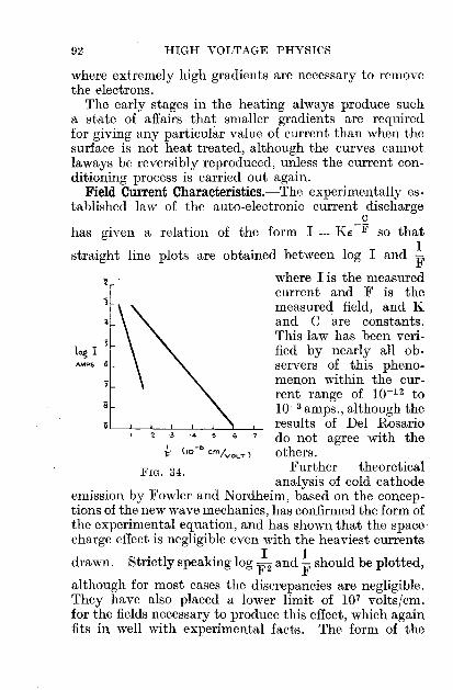
92 HIGH VOLTAGE PHYSICS
FIG. 34.
AMPS 6log I
where extremely high gradients are necessary to removethe electrons.
The early stages in the heating always produce sucha state of affairs that smaller gradients are requiredfor giving any particular value of current than when thesurface is not heat treated, although the curves cannotlaways be reversibly reproduced, unless the current conditioning process is carried out again.
Field Current Characteristics.-The experimentally established law of the auto-electronic current discharge
chas given a relation of the form I = KE -jf so that
1straight line plots are obtained between log I and F
where I is the measuredcurrent and F is themeasured field, and Kand C are constants.This law has been verified by nearly all observers of this phenomenon within the current range of 10-12 to10-3 amps., although theresults of Del Rosario
'34 67 do not agree with the*' (10-
0em/VOLT) others.
Further theoreticalanalysis of cold cathode
emission by Fowler and Nordheim, based on the conceptions of the new wave mechanics, has confirmed the form ofthe experimental equation, and has shown that the spacecharge effect is negligible even with the heaviest currents
drawn. Strictly speaking log ';'2 and ~ should be plotted,
although for most cases the discrepancies are negligible.They have also placed a lower limit of 107 volts/em.for the fields necessary to produce this effect, which againfits in well with experimental facts. The form of the

VACUUM AS A DIELECTRIC 93
equation is interesting, as it is entirely different fromthat for the Schottky effect with which it might havebeen expected to have something in common.
In the latter case the log I, yF plot gave a straightline. If these two quantities are plotted for the autoemission case, the resulting curve as found by Millikan andEyring is concave to the axis of field, and certainly notlinear throughout. Hence, the cold cathode effect doesnot follow the Schottky law which appears to be validonly for the case of thermionic emission and in fairlyweak fields as compared with the fields necessary forfield emission. The latter usually take place from oneor two highly localized areas, where the gradient is sowry high as to completely exclude the possibility ofapplying the image law. In other words, the constantC, which is proportional to the work function of thesurface, is not at all altered by the influence of an externalfield in the cold cathode case, whereas it is distinctlydiminished by the effect of the field in the thermioniccase. This is rather important and will prove helpfulshortly when the question of temperature effects haveto be considered. The later careful work of Millikan,Eyring and McKeown on the field currents betweenclean points of tungsten, platinum, nickel and steel in theform of hyperboloids of revolution and a plane polishedtungsten disc, have shown that there is a definite criticalgradient at which for any particular point the currentbegins to appear. It is merely sufficient that this fieldbe applied at the point, quite irrespective of the relationsof applied voltage and distance, i.e. the normal log i,
~ plot gave a straight line in anyone case for various
voltages and distances, showing that the gradient is theessential factor.
This particular electrode system lends itself rathernicely to direct calculation of the field at the point, byconsidering a limiting case of two coaxial confocalparaboloids of revolution between. which the voltage is

94 HIGH VOLTAGE PHYSICS
VOLTS
FIG. 35.
log d.
applied. Following Maxwell, it can be shown that the
field E at the point = 2V2d '
rloge ( r)where r = radius of curvature at the point,
d = distance between point and plane.
Hence, for any given field, i.e. for any given current, therelation between applied voltage and log of distance
apart of point and planeshould be linear. This isindeed found to be thecase, and confirms previousobservations.
Field Currents: Temperature Effects.-The experiments of Gossling, Millikanand Lauritsen and othershave shown that there is notemperature coefficient tobe associated with fieldcurrents from tungsten
points within the temperature range 300 0 K. to 10000 K.Above llOO° K. the latter observers have found adistinct dependence on temperature, so that the totalcurrent from the cathode is now made up of two partsthe thermionic current under the strong field which isgiven by the Schottky effect, and the field current uponwhich it is superposed. The total current is thus given by
[e</>_(e3F//2 j C
I = AT2€ kT + A'F2€-T+dF.
The difficulty in the experiment is to be able to isolateeach current separately and observe its effect. That theeffect is real and permanent can be seen from Millikanand Eyring's work, where the observed currents at llOO°K. were about 10-4 amperes, whereas the thermioniccurrent after allowing for the Schottky effect was only10-12 amperes. The temperature dependence was again

VACUUM AS A DIELECTRIC 95
1210 IICJ8
104
T36.
7
FIG.
6
iHERMIONIC
eMISSION
54
;;
log, 1. "AMPS ..-
verified by Millikan and Lauritsen, as seen from the formof their curve (Fig. 36).
Up to about 800 0 K. there is little or no rise incurrent; but at about llOO° K. the current has increasedby about 20 per cent., although the thermionic portionof it contributes something considerably less than afraction of 1 per cent.
At higher temperatures, of course, the thermionicemission is very large and completely masks the fieldemission.
The most recent work-that of Ahearn, in this connection, while notentirely disprovingthe temperature effect, shows that in thecase of clean tungstenand molybdenum cathodes no such effectcould be detected upto temperatures of14000 K.
This non-dependence of the field current 'with temperatures up to over10000 K. is somewhat difficult to explain from the pointof view of classical dynamical theory, where the meanelectron energy was supposed to vary directly with theabsolute temperature, and the bulk of the electrons hadvelocities very close to the mean value, according tothe classical gas laws. The later modifications ofDrude's electron gas theory by Sommerfeld and theintroduction of the new statistical mechanics by 'Fermiand Dirac have shown that even at 0 0 Abs. the electrons take on a whole series of energy states, startingfrom zero energy for some particular electron and extending up to some critical velocity which appearedto be practically independent of temperature at allordinary temperatures. The number of electrons having

96 HIGH VOLTAGE PHYSICS
FIG. 37.
c
DISTANCE FROM $URI=A,CE
POTENTIAL
'a velocity above this critical value was small at ordinarytemperatures, but increased with temperature. At hightemperatures the new distribution is found to blend intothe old, which is then valid. This new type of electronvelocity distribution, being so completely opposed tothe classical view, is the fundamental difference onwhich the new mechanics has been built up-the electron gas now being termed "degenerate." The otherdifference consists in endowing the electron with characteristic wave-like properties on certain occasions andparticle properties on others. Thus have many of theprevious difficulties in connection with the behaviourof metals, such as specific heats, etc., been explainedsatisfactorily.
The applications of the new methods by Nordheimand Fowler to thermionic emission and to the extractionof electrons from cold metals by intense fields have ledto some striking successes. The grounds on which thenon-dependence on temperature of the field currents upto over lOOOoK. have been established can be explainedin terms of the groups of electrons having velocities nearor at the critical velocity. These are the electrons whichmainly give rise to the electrical conductivity of the
metal; they also furnishthe electrons for field current phenomena.
In the latter case theelectrons striking the surface normally, and havingenergy 'V, are consideredas equivalent to a seriesof wave trains passingthrough the surface; thepotential energy of theelectrons then varies as
shown. The electron loses energy C on passing throughthe surface, because it must have at least this energybefore it can penetrate the surface. These authors givethe emission current by the following formula :-
VAGCUM AS A DIELECTRIC 97
where X = C - !L = thermionic work function,!L = parameter equivalent to the thermody
namic partial potential of an electron,F = field.
This is readily seen to be of the same general type as theexperimentally established field current equation.
The Flash Arc.-This is the type of vacuum breakdownobtained when energy at a sufficiently high potential,for example a charged condenser, is applied to twoelectrodes, spaced 2-3 mm., in the high vacuum. As itsname implies, ·the resulting discharge is rather characteristic of an arc in that the breakdown is complete (buttransient), and is attended by the appearanc of abrilliant white, yellow or blue scintillation on the cathode.It thus represents the most complete form of vacuumbreakdown, the vacuum only being able to support 1000volts or so during the passage of the discharge, whichusually carries hundreds of amperes. One of its mostinteresting features is the" build-up" during the earlystages. The work of Hull and Burger with tungstenelectrodes, and later of Snoddy with copper electrodes,using the cathode ray oscillograph, has shown thatduring its early stages the discharge starts as a pureelectron discharge, lasting up to less than 5 X 10⁻⁷ secs.
The current-voltage law as recorded by the oscillograph for this stage was such as to warrant the conclusion that the discharge starts as a 'field current'from the cathode, which in less than 10-7 secs. changesinto the low voltage vapour arc. The rotating mirrormethod when applied by Snoddy for viewing the discharge showed the appearance of a luminous spot on theanode, due probably to the initial 'field current'bombardment and lasting from 1--4 X 10⁻⁷ secs. Thismay disappear if the discharge is not heavy enough.This was followed a little later by the cathode scintilla_
7

98 HIGH VOLTAGE PHYSICS
tion already referred to, which lasted throughout thedischarge. The rather extensive work of Gossling onthe subject, while confirming, in general, the abovefeatures, has shown that as much as 80 per cent. of theavailable energy may be -required to be dissipated (provided always that the voltage be high enough) beforethe discharge starts. Using a peak voltmeter in thelow voltage side of his discharge circuit (with knownconstants), he has been able to measure these transitorydischarge currents of hundreds of amperes lasting foronly a fraction of a microsecond.
As is to be expected, the intensity of the dischargedepends on (1) the material of the electrodes and theirsurface condition, being for instance more intense witha nickel cathode than with a molybdenum one for thesame previous treatment, (2) energy available for discharge. With any particular set up of electrodes it isusual to find the flash arc taking place at comparativelylow voltage for the first discharges-15-20 KV. for3 mm. clearances between copper anode and molybdenumcathode. This voltage progressively increases with thenumber of discharges passed through the system, untila stage may be reached at which 100 KV. will not producebreakdown. During the passage of these dischargesthe free gas pressure in the tube may increase quiteappreciably, without having any marked effect on thedischarge voltage in either direction; however, if someof this gas is allowed to clean up electrically on to theelectrodes inside the valve, a pressure change of 10-6 mm.being sufficient, a definite and consistent relapse to lowervoltage is induced. This change is not at all permanent,as the voltage again progressively increases with furtherdischarges.
Another important feature of the discharge, whichGossling has brought out, is the presence of a time-lagbetween the actual application of the voltage to thedischarge tube and the appearance of the flash arc.H a discharge has been taken instantaneously at anyparticular voltage, then a reduction of the voltage by

VACUUM AS A DIELECTRIC 99
3 per cent. is sufficient to cause a time-lag of the orderof minutes before the discharge will again take place;in fact, a ratio of at least 10/1 may represent two successive time-lags at any particular voltage. Such a resultis undoubtedly connected with surface changes on theelectrodes due to passage of the discharge, althoughthe exact causes are not definitely known. In additionto these short time-lags, longer time-lags up to thousandsof hours have been recorded in many cases. The explanations put forward by Gossling for the short timelags assume that the field current, which, as was seen,initiates the discharge, is the responsible agent in bringingabout a time-lag. In the first instance, the one or twominute spots on the cathode surface from which thefield currents proceed are, by reason of the extremelyhigh field there, under a severe electrostatic tensionwhich may disrupt the surface. Thus, in the case oftungsten and with fields of the order of 108 volts/em.,this stress may reach values of several tons per squareinch of surface. The subsequent slow yielding of theirregular mountain peaks is the contributing factor in thetime-lag effect. When once the surface has broken inthis way it can be expected to furnish further discharges under somewhat similar conditions, until theapplied field is no longer able to initiate the field current.The surface is then fatigued for this particular fieldstrength.
Again, it can easily be conceived (as an analogy withthe Schrot effect in the case of thermionic emission),that the prime necessity for explaining the time-lag isthe presence of an auto-electronic current above somefixed critical value which triggers off the discharge.The probability of any such spontaneous variation inthe field current is such that the 10/1 ratio with 3 percent. decrease in discharge voltage can be convenientlyexplained.
Whichever explanation is on the right track, it isinteresting to record in this connection that in Gossling'sexperiments the presence of superposed auto-electronic

100 HIGH VOLTAGE PHYSICS
emission (of up to several hundred microamperes) atvoltages below the discharge voltage for the system,did not greatly tend either to lessen the discharge voltageappreciably, or to make for regularity in the time-lags.
This is somewhat unexpected, in view of previousassumptions, but the unknown. local conditions on theelectrode surface are almost certain to play an importantpart in determining the resultant discharge.

P.R.P.R.S.J.F.I.J.I.(A.)E.E.
ABBREVIATIONS TO JOURNALS
= Physical Review.= Proceedings oj Royal Society.= .Journal oj Franklin Institute.= Journal oj Institution (American) Electrical
Engineers.Ann. der Phys. = Annalen der Physik.Zeits. j. Phys. = Zeitschrijt jur Physik.P.M. = Philosophical Magazine.P.C.P.S. = Proceedings oj Cambridge Philosophical Society.C.R. = Comptes Rendus.
BIBLIOGRAPHY
CHAPTER I
'-an de Graaf, Compton, Van Atta, P.R., 43, No.3, p. 149, 1933.Fortescue, Proc. Phys. Soc., Lond., 31, p. 319, 1919.Xorris and Taylor, J.I.E.E., 69, p. 673, 1931-Breit, Tuve and Dahl, P.R., 35, p. 51, 1930.Whitehead and Castellain, J.I.E.E., 69, p. 898, 1931.Davis, Bowdler and Standring, J.I.E.E., 68, p. 1222, 1930.Whitehead and Isshiki, J.I.(A.)E.E., 39, p. 441, 1920.Thornton, 'Vaters and Thompson, J.I.E.E., 69, p. 533, 1931.Thornton, J.I.E.E., 69, p. 1273, 1931.
CHAPTER II
J. J. Thomson, Electricity and Magnetism, Cambridge Univ.Press.
CHAPTER III
J. J. and G. P. Thomson, Conduction thrdugh Gases, vol. 2, C.U.P.Davisson, J.F.I., 208, p. 595, 1929.Davisson and Germer, P.R., 30, p. 704, 1927.G. P. Thomson, P.R.S., 117, p. 600, 1928; 119, p. 651, 1928;
128, p. 649, 1930; 125, p. 352, 1929; 133, p. 1, 1931.101

102 HIGH VOLTAGE PHYSICS
Mott, P.R.S., 124, p. 425, 1929.Rupp, Ann. der Phys., 10, p. 927, 1933; 85, p. 981, 1928;
Zeits. f. Phys., 53, 7-8, p. 548, 1929.Langsroth, P.R.S., 136, p. 559, 1932.Zworykin, J.F.I., 215, p. 535, 1933.Coolidge, Dempster, Tanis, Physics, vol. 1, 1931.Farnsworth, P.R., 20, p. 358, 1922; 31, p. 405, 1928; 34, p. 679,
1929.Frohlich, Ann. der Phys., 13, p. 229, 1932.Stehberger, Ann. der Phys., 86, p. 825, 1928.Baltruschat and Starke, Physikalische Zeits., 23, p. 403, 1922.'Wagner, P.R., 35, p. 98, 1930.Schonland, P.R.S., 104,p. 235, 1923; 108, p. 187, 1925; 113,
p. 87, 1927.Bethe, Zeits. j. Phys., 76, p. 293, 1932.Terril, P.R., 22, p. 101, 1923.Allen, J.F.I., 208, p. 217; 214, pp. 25, 43, 1932.Bothe, Zeits.j. Phys., 54,161,1929.Klemperer, Zeits. j. Phys., 34, p. 532, 1925.White and Millington, P.R.s., 120, p. 701, 1928.Wentzel, Ann. der Phys., 69, 5, p. 335, 1922.Neher, P.R., 38, p. 1321, 1931.Darwin, P.M., 23, p. 907, 1912.Crowther and Schonland, P.R.S., 100, p. 526, 1922.Liska, P.R., 46, p. 169, Aug., 1934.
CHAPTER IV
J. J. and G. P. Thomson, Gonduction through Gases, vol. 2, C.U.P.Kunsman, Harnwell and Barton, P.R., 27, p. 739, 1926.Cockcroft and Walton, P.R.S., 129, p. 477, 1930; 136, p. 619,
1932; 137, 229, 1932.Ising, Arlciv. jor Matematik och Fysik, vol. 18, no. 30, Stockholm,
1924.Sloan and Lawrence, P.R., 38, p. 834, 1931; 38, p. 2021, 1931.Sutton and Mouzon, P.R., 35, p. 694, 1930.Gurney, P.R., 32, p. 795, 1928.Frische, P.R., 43, p. 160, 1933.Goldman, Ann. der Phys., 5, 10 (vol. 402), p. 460, 1931.Verwiebe, P.R., 44, p. 15, 1933.Rudnick, P.R., 38, p. 1342, 1931.Batho, P.R., 42, p. 753, 1932.Jackson, P.R., 28, p. 524, 1926; 30. p. 473, 1927.Oliphant, P.G.P.S., 24, p. 451, 1928; P.R.S., 132, p. 631, 1931 ;
127, p. 373, 1930.Baerwald, Ann. der Phys., 41, p. 643, 1913.Gerthsen, Zeits. j. Phys., 31, p. 948, 1930; Ann. de·r Phys.,
5, 5, p. 657; 86, p. 1025, 1928.

BIBLIOGRAPHY 103
Eckard, Ann. der Phys., 5, p. 401, 1930.Chadwick, P.R.S., 136, p. 692, 1932.Curie and Joliot, G.R., 194, p. 273, 1932.Lawrence, Livingston and White, P.R., 42, p. 150, 1932.Henderson, P.R., 43, p. 98, 1933.Lauritsen and Crane, P.R., 45, 1st March, p. 345, 1934.Wertenstein, Gong1'eslnternational d'Electricite Paris Rpt., No. 17,
1932.Tuve, J.P. I., 216, no. 1, 1933.Coates, P.R., 43, p. 837, 1933.Lawrence, Livingston and Lewis, P.R., 44, pp. 55, 56, 1933.
CHAPTER V
Peek, Dielectric Phenomena, 3rd edition, chaps. 4, 5, 6, :l\IcGrawHill.
S. \Vhitehead, Dielectric Phenomena: Electrical Discharges 1'nGases, Benn.
Townsend, Electricity in Gases, Oxford Press.Schwaiger, Theory of Dielectrics, Chapman & Hall.Goodlet, Perry and Edwards, J.1.E.E., 69, p. 695, 1931.Booth, P.R., 10, p. 266, 1917.Zeleny, P.R., 25, p. 307, 1907.Meservey, P.M., 21, p. 480, 1911.Beams, P.R., 28, p. 475, 1926; J.P.I., 216, p. 809, 1928.Lawrence and Dunnington, P.R., 35, p. 396, 1930.Whitehead and Castellain, J.I.E.E., 69, p. 898, 1931.Hayashi, Ann. der Phys., 45, p. 431, 1914.Torok, J.I.(A.)E.E., 47, p. 177, 1928.Rogowski, Arch. j. Electrotechnik, 25, p. 596, 1931.Loeb, Science, 69, p. 509, 1929.Stephenson, Phys. Soc. Pl'Oc., 45, p. 24, 1933; P.M., 15, p. 241,
1933.
CHAPTER VI
Peek, Dielectric PhIJnomena, 3rd edition, chaps. 7, 8, 11,McGraw-Hill.
S. ·Whitehead, Dielectric Phenomena: Breakdown of SolidDi.electrics, Benn.
Schwaiger, Thewy of Dielectrics, Chapman & Hall.J. J. Thomson, Electricity and Magnetism.Williams, J.P.I., 211, p. 581, 1931.Hartshorn, J.I.E.E., 64, p. 1152, 1926.Wagner, J.1.(A.)E.E., 41, p. 1034, 1912.Warburg, Ann. del' Phys., 40, p. 327, 1913.

104 HIGH VOLTAGE PHYSICS
Robinson, Physics, 2, p. 52, 1932.Terada, Hirato and Yamamoto, Inst. Phys. and Ghcm. Research,
'l'oT.yo, Sept., 1\)32.Hayner, Standring, Davis and Bowdler, J.I.E.E., 68, p. 1132,
1930.lnge and Walther, Arch. jur Elektrotechnik, 22, p. 410, 1929;
24, p. 88, 1930.Jost, Arch. fur Elektrotechnik, 23, p. 305, 1929.Black and Nisbet, P.M., 10, p. 842, 1930.Nikuradse and RussichurJi, Ann. der Phys., 8, p. 811, 1931.Welo, Physics, 1, p. 160, 1931.Washburn, Physics, vol. 4, 1933.Goodlet, Perry and Edwards, J.I.E.E., 69, p. 695, 1931.
CHAPTER VII
Broxon, P.R., 20, p. 476, 1922.'Vood, P.R., 5, p. 1, 1897.Gossling, P.M., 1, p. 609, 1926.Newman, P.M., 1, p. 940, 1926; 2, p. 796, 1926.Tanberg, P.R., 35, p. 1080, 1930.Berkey and Mason, P.R., 38, p. 943, 1931.Schottky, Ann. der Phys., 44, p. 1011, 1914; Phys. Zeits., 15,
p.872, 1914; Zeits. f. Phys., 14, p. 63, 1923.Becker and Mueller, P.R., 31, p. 431, 1928.De Bruyne, P.R.S., A, 120, p. 423; P.G.P.S., 24, p. 518, 1928.Millikan and Shackelford, P.R., 15, p. 239, 1920.Gossling, Fowler and Stern, P.R.S., A, 124, p. 699, 1929.Del Rosario, J.F.I., 203, p. 243, 1927.Millikan, Eyring and McKeown, P.R., 31, p. 900, 1928.Hume-Rothery, The Metallic State, p. 248, etc., Oxford Press.Hull and Burger, P.R., 31, p. 1121, 1928.Gossling, J.I.E.E., 71, p. 460, 1932.

INDEXOI:-particles, 49, etc.Absorption dielectric, 69, 76
electron, 32, 33, 34, 35positive ion, 47
AHEARN, 29, 95Air as dielectric, 53
discharge, 53electric strength, .56spark, 54, 61, etc.
ALLEN, 36Arc spectra, 83, 85
vacuum, 82, 83Auto-electronic currents, 81
BEAMS, 61BECKER, 30, 36, 87BETHE,34Biphase circuit, 5BOHR,34Bombardment, electron, 28
nuclear, 48, etc.BOWDLER, 9, 13Breakdown-
and thickness, 71duration of stress, 74, 75effect of barriers, 79
of impurities, 77of pressure, 79of temperature, 71, 79
endurance test, 75impulse, 74liquids, 76, etc.minute test, 75power loss and frequency. 72pre-stressing, 79solids, 70strength, 71, 77surface, 71voltage (B.D.V.), 71
BREIT,5BROXON,81Brush discharge, 54
7*
Capacity smoothing, 4Cascade connection, 4CASTELLA~, 10, 63Cathode rays, 27, 28
bombardment, 28spot, 83, 84tubes, 27, 28
CHADWICK, 37, 49Charging current, 13COCKCROFT, 42, 49Concentric cylinders, 17
spheres, 18Condenser potential divider, 12Conditioning, 91Conduction, liquids, 75, 76
solids, 69COOLIDGE, 27, 28, 29Corona, 55, 57
coaxial cylinders, 56current, 60effect of frequency, 55
of humidity, 14, 55of pressure, 58
on spheres, 57parallel wires, 55potential distribution, 57voltmeter, 14
CRANE, 52Critical distance, 54CURIE and JOLIOT, 49Cylinders, coaxial, 17
parallel, 18
DAHL,5Dark discharge, 53DAVISSON,21DE BROGLIE, 21DEMPSTER, 27, 29, 45Deuton bombardment, 51Dielectrics-
abnormal properties, 68absorption, 69, 76
105

106 HIGH VOLTAGE PHYSICS
Dielectrics (cont.)breakdo~, 70, 76, 79, 89conduction, 68, 69, 75, 76in parallel and series, 19polarization, 68solids and liquids, 68
Diffraction (electron), 22, 23DIRAC, 24Discharge in air, 53, 54Disintegration (nuclear), 48,
etc.Distribution (velocity), 31DUNNINGTOX, 61
ECKARD, 47, 48EDWARDS, 54, 78Electric fields, 16
strength, 56, 71, 74, 81wind, 15
Electron absorption, 32bombardment, 28diffraction, 22distribution, 95, 96ionization, 32, 33optics, 25penetration, 24polarization, 24rediffusion, 30scattering, 37secondary, 29, 46transmission, 32velocity, 22waves, 21
Electrostatic focussing, 26generator, 2voltmeter, 10, 12
Ellipsoid voltmeter, 12Emission, secondary, 29Endurance test, 75EYRING, 93, 94
Field currents, 81, 88, 92, 97electrons, 96temperature effects, 94
Flash arc, 82, 97time-lag, 98
Focussing, electrostatic, 26magnetic, 25
GERMER, 21GERTHSEN,47Glow discharge, 53GOODLET,54,78GOSSLING, 82, 89, 90, 94, 98Gradient, 16, 93GRAETZ circuit, 5GREINACHER circuit, 7
Half-wave circuit, 5HARNWELL, 42Helium bombardment, 52HENDERSON,51High frequency, 63, 65, 74
resistance, 9
Impulse breakdown, 74, 77circuit, 7ratio, 66, 67
Insulation resistance, 68Ionic wind voltmeter, 1.5Ionization electron, 32
neutral atoms, 45positive ion, 44probability, 33, 44(surface), 29
ISING,43 ....
KERR cell, 61KIKUCHI,22KLEMPERER, 36KUNSMAN,42
LAURITSEN,52LAWRENCE, 42, 51, 61LENARD, 27, 34, 35Liquids: breakdown, 77
conduction, 75LIVINGSTON, 51
Magnetic focussing, 25MARX circuit, 7MESERVEY, .59MILLIKAN, 93, 94Minute test, 75MOTT, 24, 39MOUZON,44

INDEX 107
Needle gap, 65NEHER, 31, 39Neutron, 49NEWMAN, 83NORDHEIM, 92, 96Nuclear bombardment, 48
OLIPHANT 46, 52Oscillograph, 8
Parallel cylinders, 18plate, 17
PASCHEN'S law, 63PEEK, 56, etc., 64, 67, 75PERRY, 54, 78Point and plane, 18, 58, 64
electrodes, 58Polarization, 68Positive ion,
absorption, 47ionization, 44scattering, 47sources, 42
Potential divider, 12distribution, 57
Power factor, 69, 72, 73Prestressing, 79Probability (ionisation), 33, 44Protons, 45, 49, 50
Rediffusion (electron), 30Resistance (high), 9ROBINSON, 69RUDNICK, 45RUTHERFORD, 37, 39, 52
Scattering, 37, 47SCHERING bridge, 73SCHONLAND,33,38SCHOTTKY effect, 85Secondary emission, 29, 30, 31,
46SLOAN,42SOLTAN,52Space charge, 68, 75Spark discharge, 54
lag, 61, 66
Sparkover, II, 61, 78concentric cylinders, 65effect of humidity, 10, 63effect of pressure, 64(electrode surface), 63needle gap, 65parallel wires, 66, 67point and plane, 64sphere gap, 9, 65
Spectrum velocity, 31Sphere, corona on, 57
gap, 9, 65Spheres, concentric, 18STANDRING, 13Surface conditioning, 91
ionisation, 29field, 86, 88
SUTTON,44
TANBERG, 83TANIS, 27, 29TERRIL,35TESLA coil, 3, 5, 42THOMSON, 21, 32,35THORNTON, 12Time-lag, 66Transformer, 3
ratio, 8Transmission (electron), 32, 34TUVE,5
Vacuum are, 82, 83breakdown, 89electric strength of, 81
VAN ATTA, 2VAN DE GRAAF, 2Velocity distribution, 31,36, 46
spectrum, 31VILLARD circuit, 7Voltage multiplication, 6
WAGNER, 31WALTON, 42WHITE, 23, 36, 51WHITEHEAD, 10, 14, 63WITKA circuit, 7WOOD, 82, 88Work function, 85, 90, 93

PRINTED IN GREAT BRITAIN AT
THE UNIVERSITY PRESS, ABERDEEN

METHUEN
=
Books on
PHYSICS & CHEMISTRY

A SELECTION OF BOOKS
ON PHYSICS AND CHEMISTRY
PHYSICSGENERAL PHYSICS
GRADED EXAMPLES IN PHYSICS. By R. L. CHEETHAM. With SDiagrams. Feap. 8vo. IS. gd. (Up to Sehooi Certificate Standard.)
A PHYSICS NOTEBOOK: HEAT, LIGHT AND SOUND. By E. W.TAPPER. With 53 Diagrams. Feap. 8vo. 2S.
TEST E~"nNATIONSIN PHYSICS. By A. W. ANSCOMBE. IS. 3d.
mGHER CERTIFICATE PHYSICS TEST PAPERS. Bv A. H. COOPER,11.Sc., B.A. With Answers. Third Edition. Feap. 8vo: IS. 6d.
EXAMPLES IN PHYSICS. By C. E. JACKSON, M.A. With Answers.Tenth Edition. Crewa 8vo, 35. Also Part I (Secondary Course), IS. 6d;Part II (Scholarship Course), IS. gd.
THE PROPERTIES OF MATTER. By A. E. GODDARD and H. F. BOULIND,M.A. With lI5 Diagrams. Crown 8vo. 4S. Also in two parts, 2S. 6d.each.
A TEXTBOOK OF INTERMEDIATE PHYSICS. By H. MOORE, D.Sc.,A.R.C.Sc., F.lnst.P. With 560 Diagrams. Fourth Edition. Demy 8vo.18s. net.
ADVANCED PRACTICAL PHYSICS FOR STUDENTS. By R L.WORSNOP, B.Se., Ph.D., and H. T. FLINT, M.Sc., Ph.D. With 404 Diagramsand Illnstrations. Third Editi01.. Demy 8vo. 2IS. net.
THE KINETIC THEORY OF 'OASES. By EUG);;NE BLOCH, Professor atthe Lyee. St. Lonis. Translated by P. A. SMITH, B.A. Second Edition,Revised. CrO"dln Bvo. 7s. net.
THERMIONIC PHENOMENA. By EUG""E BLOCIL Translated byJ. R. CLARKE, M.Sc., F.Inst.P. With 2{ Diagrams. Crown 8vo. 75. Mnet.
MODERN PHYSICS. A General Survey of its Principles. By THEODOR W UL',S.J. Translated fTom the German by C. J. SIlITH, Ph.D., M.Sc., A.KC.S.With 202 Diagrams. Royal Bvo. 355. net.
CRYSTALS AND THE FINE-STRUCTVRE OF MATTER. ByFRIEDRICH RINNE. Translated by WALTER S. STILES, B.Se. With aDra\ving by A. DURER, and Portraits of tha leading investigators, and 203Figures. Demy Bvo. lOS. 6d. net.
THE PRINCIPLES OF PHYSICAL OPTICS. By ERNST MACH. Tram·tated by JOHN S. ANDERSO", M.A., D.Se., Ph.D., and A. F.A. YOUNG, B.Sc.,Ph.D. With 290 Illustrations. Demy 8tlO. 2IS. net.
MODERN MAGNETICS. By FELIX AUERB.'CH. Translated by H. C.BOOTH, A.KC.Sc. With 167 Diagrams. D,rny S..,. 1$', fill·

BOOKS ON PHYSICS AND CHEMISTRY
RADIOACTIVITY; AND THE LATEST DEVELOPMENTS IN THESTUDY OF TP.E CHEMICAL ELEMENTS. By K. FAJASS. Translated by T. S. WHEELER, B.Sc.(Lond.), A.R.e.Se.I., A.I.e.; and W. G.KING. With 25 Diagrams and Tables. Demy 8vo. 8s. 6d. net.
X-RAYS. By 1JAURICE DE BROGLIE. Translated by J. R. CLARKE, M.Sc.,F.Inst.P. \Vith 7 Illustrations and 39 Diagrams. Demy 8vo. 12S. 6d. net.
THE NEW HEAT THEOREM: ITS FOUNDATIONS IN THEORYAND EXPERIMENT. By W. NERNST. Translated by GUY BARR, B.A.,D.Se. 'Vith 21 Diagrams. Demy 8t'o. 1.25. 6d. net.
THEORETICAL PHYSICS. By W. WILSON, F.R.S. In Three Volumes.Demy 8vo. Vol. I. MECHANICS AND HEAT (Newton-Carnot). With 80Diagrams. 215. net. Vol. II. ELECTROMAGNETISM AND OPTICS (MaxwellLorentz). With 78 Diagrams. 18s. net.
MODERN THERMODYNAMICS BY THE METHODS OFWILLARD GffiBS. By E. A. GUGGENHEIM, M.A. With 10 DiagraIllS.Demy 8<'0. lOS. 6d. net. !
METHUEN'S MONOGRAPHS ON PHYSICALSUBJECTS
General Editor: B. L. WORSNOP, B.Se., Ph.D.Illustrated. Fcap. 8vo. Each. 2S. 6d. net except where otherwise stated.
SPECTRA. By R. C. JOHNSON, M.A. (Oxon.). Second Edition, Revisd.WAVE MECHANICS. By H. T. FLINT, D.Se., Ph.D. Second Edition,
Revised and Enlarged. 3S. 6d. net.THE PHYSICAL PRINCIPLES OF WIRELESS. By J. A. RATCLIFFE,
M.A. Third Editi,m, Revised and Enlarged.
THE CONDUCTION OF ELECTRICITY THROUGH GASES. ByProf. K. G. EMELEUS, M.A., Ph.D.
MAGNETISM. By E. C. STnNER, Ph.D.
X·RAYS. By B. L. WORS"OP, B.se., Ph.D.
X.RAY CRYSTALLOGRAPHY. By R. W. JAMES, M.A., B.Se.
THE COMMUTATOR MOTOR. By Prof. J. TEACO, D.Se.THE APPLICATIONS OF INTERFEROMETRY. By W. EWART
\VILLIAMS, M.Sc.
PHOTOCHEMISTRY. By D. W. G. STYLE, B.Se., Ph.D.
THER.l\10DYNAMICS. By Prof. A. W. PORTER, D.Se., F.R.S.THERt'\1IONIC VACUUM TUBES. By Prof. E. V. ApPLETON, M.A., D.Se.,
F.R.S. Second Edition, Re<~sed. 3S. net.WIRELESS RECEIVERS. Dy C. W. OATLEY, M.A., M.So.
ATMOS~HERIC ELECTRICITY. By B. F. J. SeHoNLA"D, O.B.E.,M.A., Ph.D.
THE METHOD OF DLMENSIONS. By Prof. A. W. PORTER, D.Se.
COLLISION PROCESSES IN GASES. By F. L. ARNOT, B.Se. 35. 'Iel.

METHUEN'S BOOKS ON
ELECTROMAGNETIC WAVES. By F. W. G. WHITE, M.Se. 3S. net.
PHYSICAL CONSTANTS. By W. H. J. CHILDS, B.Se., Ph.D.
THE GElI.'ERAL PRINCIPLES OF QUANTUM THEORY. By Prof. G.TE;\IPLE, Ph.D., D.Se. 3s. net.
THE KINETIC THEORY OF·GASES. By Prof. MARTIN KNUDSEN.
LOW TEMPERATURE PHYSICS. By L. C. JACKSON, M.Se. 35. net.
mGH VOLTAGE PHYSICS. By L. JACOB, M.Se. 35. net.
RELATIVITY PHYSICS. By W. H. MCCREA, M.A., B.Se.
FINE STRUCTURE IN LINE SPECTRA AND NUCLEAR SPIN. ByS. TOLANSKY, B.Se., Ph.D.
In Preparation
THERMIONIC EMISSION. By T. J. JONES, M.Se.
SURFACE TENSION. By ALLAN FERGUSON, M.A., D.Se.
THE NUCLEUS. By Prof. J. A. CROWTHER, M.A., D.Se.
INFRA-RED AND RAMAN SPECTRA. By Dr. G. B. B. M. SUTHERLAND.
ATOMIC AND QUANTUM THEORIESMAGNETISM AND MATTER. By EDMUND C. STONER, Ph.D. With
87 Diagrams. Dem-y 8'00. 215. net.AN INTRODUCTION TO ATOMIC PHYSICS. By JOHN THOMSON.
With 36 Diagrams. Demy 8'00. IDS. 6d. net.
THE STRUCTURE OF SPECTRAL TERMS. By W. M. HICKS, Sc.D.Vlith 6 Diagrams. Demy 8vo. IDS. 6d. net.
THE BASIS OF MODERN ATOMIC THEORY. By e. H. DOUGLASCLARK, B.Se., D.Le. With 44 Diagrams. C,-ow" 8vo. 85. 6d. net.
THE CHEMICAL ELEMENTS. By F. H. LORING. Demy 8vo. 85. 6d. net.
ATOMIC THEORIES. By F. H. LORING. With 67 Figures. Secon..iEdition, Rev£sed. Demy 8va. 12$. &1. net.
ATOMIC STRUCTURE AND SPECTRAL LINES. By ARNOLD SOmIER'FELD. Translated by HENRY L. BROSE, D.Se. \~lith 1':5 Diagrams.Third Edition, Revised. In two volumes. Demy 8vo. Vol. I. 335. net.
WAVE-MECHANICS. By ARNOLD SOMMERFELD. Translated by HENRYL. BROSE. With 33 Diagrams. Demy 8vo. 215. net.
THREE LECTURES ON ATOMIC PHYSICS. By ARNOLD SOMMERFELD.Translated by HENRY L. BROSE. With 8 Diagrams. Cr.8vo. 25. 6d. net.
AN INTRODUCTION TO THE STUDY OF WAVE MECHANICS. ByLOUIS DE BROGLIE. Translated by H. T. FLINT. Demy 8vo. 12$. 6d. rlet.
Tk THEORY OF THE BROWNIAN MOVEMENT. By ALBERTEINSTEIN. Translated by A. D. COWPEa. M.Se. Crown 8vo. 55. net.
THE NEW PHYSICS. By ARTHUR HAAs, Ph.D. Translated by R. WLAWSO~J D.Se. Third Edition, Revised and Enlarged. Crown 8vo. 6s. net,
THE QUANTUM THEORY. By FRITZ REICHE. Translated by H. S.HATFIELD and H. L. BROSE. Third Edition, Revised. CtC"'..em Bvo. 6$. net.

PHYSICS AND CHEMISTRY
THE QUANTUM AND ITS INTERPRETATION. By H. STANLEYALLEN, M.A., D.Se. With 30 Diagrams. Demy 8vo. I2S. 6d. net.
THE ELEMENTS OF THE NEW QUANTUM MECHANICS. IiI¥OTTO HALPERN and HANS THIRRING. Translated by H. L. BROSE, M.A.,D.Phil. \Vith 13 Diagrams. Demy 8vo. 125. 6d. net.
THE THEORY OF GROUPS AND QUANTUM MECHANICS. ByH. WEYL. Translated by H. P. ROBERTSON. Demy 8vo. 2IS. neI.
RELATIVITY
AN INTRODUCTION TO THE THEORY OF RELATIVITY. ByLYNDON BOLTON, M.A. With 38 Diagrams. Second Edition, Rev£sed.Crown 8vo. 55. net.
RELATIVITY: THE SPECIAL AND THE GENERAL THEORY. APopular Exposition. By ALBERT EINSTEIN. Ph.D. Authorized Transla p
tion by ROBERT W. LAWSON, D.Se. \Vith 5 Diagrams and a Portraitof the Author. Crown 8vo. 5'. net.
SIDELIGHTS ON RELATIVITY: I. ETHER AND RELATIVITY; II. GEOMETRY AND EXPERIENCE. By ALBERT EINSTEIN. Translated by G. B.JEFFERY, D.Se., and W. PERRETT, Ph.D. Croum 8vo. 3S. 6d. neI.
TIlE l\1EANING OF RELATIVITY. By ALBERT EINSTEIN. Translated byE. P. ADAMS. With 4 Diagrams. Crown 8vo. 5S. net.
RELATIVITY FOR PHYSICS STUDENTS. By G. B. JEFFERV, M.A.,D.Se. \~lith 4 Diagrams. Grawn 8vo. 65. net.
TIlE PRINCIPLE OF RELATIVITY. By ALBERT EINSTEIN, H. A. LORENT2,H. l\IINKOWSKI, and H. "VEYL. With Notes by A. SOMMERFELD. Trans..lated by W. PERRETT, Ph.D., and G. B. JEFFERY, D.Se. With 8 Diagrams.Dem}' 8vo. 125. 6d. net.
TIlE FOUNDATIONS OF EINSTEIN'S TIlEORY OF GRAVITATION.By ER\VIN FREUNDLICH. Translated by HE~RY 1... BROSE, M.A. Crown8vo. 65. net.
THE THEORY OF RELATIVITY. By ERWIN FREUNDLICH. Translatedby HENRY L. BROSE, M.A. CrlYo1Jn 8vo. 55. net.
EINSTEIN'S THEORY OF RELATIVITY. By MAX BORN. Translatedby HENRY L. BROSE, M.A. With 135 Diagrams. Demy 8vo. I2S. net.
CHEMISTRYMETHUEN'S MONOGRAPHS ON CHEMICAL
SUBJECTSGeneral Editor: C. S. SAuro~, !l-LSc.
Illustrated. Fcap. 8vo. 25. 6d. net each.
TIlE ADSORPTION OF GASES BY SOLIDS. By S. J. GREGG, B.5e.
THE GALVANIC CELL AND ELECTROLYSIS. By J. A. V. BUTLER.
FLA..1\IE. By O. C. DE C. ELLIS and W. A. KIRBY, M.Sc., Ph.D.
DISTILLATION. By JOSEPH REILLY, M.A.

METHUEN'S BOOKS ON
INORGANIC CHEMISTRY
THE COMPLETE SCHOOL CHEMISTRY. By F. M. OLDHAM, M.A.vVith 128 Diagrams. Crown. 8vo. 6s.
TEST EXAMINATIONS IN CHEMISTRY. By F. M. OLDHAM, M.A.Second Edition. With Aoswers. Fcap. 8vo. IS. 3d.
Examination Papers of :Matriculation and School Certificate standa~d.
mGHER CERTIFICATE CHEMISTRY TEST PAPERS. By J.MORRIS, M.A. Third Edition. With Answers. Fcap. 8vo. IS. 6d.
OUTLINES OF INORGANIC CHEMISTRY. By J. MORRIS, M.A. (Oxon.).With 129 Diagrams. Crawn 8vo. 7S. 6d.
Also in Two Parts: I. NON·METALS AND SOME COMMON METALS. ForMatriculation Students. 4S. II. METALS AND PHYSICAL CHEMISTRY.
FOI Intermediate Students. 4S.
ErnMENTARY CHEMICAL THEORY. By J. M. WADlIIORE, M.A. With16 Diagrams. Crown BVD. 5S.
A SENIOR EXPERIMENTAL CHEMISTRY. By A. E. DUNSTAN, D.Se.,F.I.G., and F. B. THOLE, D.Se. With 125 Diagrams by E. D. GRIFFITHS,B.Se. Crow" 8vo. 7s. 6d.
A TEXTBOOK OF INORGANIC CHEMISTRY. By GEORGE SENTER,D.Se., Ph.D., F .I.C., Principal, Birkbeek College. With 90 Diagrams,Questions and Answers. Foo.trteenth Edition, Revised. Crown 8vo. 75. 6d.
CHEMICAL SYMBOLS, FORMUL.IE, AND CALCULATIONS. ByA. W. WELLINGS, B.sc. With Logarithmic Tables. Crown 8vo. 3S.
AN INTRODUCTION TO QUANTITATIVE ANALYSIS. By S. J. M.AULD, D.Se.(Lond.), Ph.D.(Wiirzburg), F.I.C., F.C.S. With 74 Diagramsand an Apper,dix. Crown 8vo. 6s.
QUALITATIVE INORGANIC ANALYSIS. By D. R. SNELLGROVE, Ph.D.,A.I.C., and J. L. WHITE, D.Se. CrauJn 8vo. 7s. 6d.
VOLUMETRIC ANALYSIS. By A. W. WELLINGS, B.Se. Crawn 8vo. 5s.
ORGANIC CHEMISTRY
A CONCISE SUMMARY OF ELEMENTARY ORGANIC CHEl\nSTRY.By F. H. CONSTABLE, M.A., D.Se., Ph.D., F.I.C., Fellow of St. John'sCollege, Cambridge. Crawn 8vo. 4S. 6d.
QUALITATIVE ORGANIC ANALYSIS. By F. B. THOLE, D.Se. With anIntroduction by A. E. DUNSTAX, D.Se., F.Le. CrO"..vn 8vo. 2,-;. 6d.
MODERN RESEARCH IN ORGANIC CHEMISTRY. By F. G. POPE,D.Se.(Lond.), F.G.S. Crawn 8vo. 73. 6d.
NATURAL TERPENES. By J. W. BAKER, D.Se., Ph.D., A.R.C.S., A.I.e.Crown 8vo. 6s.

PHYSICS AND CHEMISTRY
PHYSICAL CHEMISTRY
A FIRST YEAR PIIYSICAL CHEMISTRY. By T. P. HILDITCH, D.Se.,F.I.C. With 58 Diagrams and an Appendix. Crown 8vo. 25. 6d.
OUTLINES OF PHYSICAL CHEMISTRY. By GEORGE SENTER, D.Se.,Ph.D., Principal, Birkbeck College. With 46 Diagrams, Problems. andQuestions, and Appendix. Seventeenth Edition. Cnr&H avo. 75. 6d.
PRACTICAL PHYSICAL CHEMISTRY. By J. B. FrRTH, D.Se., F.I.C.With 74 Diagrams and an Appendix. CrO"o1Jn 8vo. 45. 6d.
A TEXTBOOK OF PRACTICAL PHYSICAL CHEMISTRY. By K.FAJANS and J. WUST. Translated by BRYAN TOPLEY, M.A. With aPreface by F. G. DONNAN, F.R.S. With 74 Diagrams. Demy 8vo. ISS. net.
PHYSICO-CHEMICAL CALCULATIONS. By JOSEPH KNOX, D.Se.Containing 365 Problems, with Answers and (in many cases) fnll Solntions. T entil Editi,,,,. Crown 8vo. 45. 6d.
A SUMMARY OF PHYSICAL CHEMISTRY. By K. ARNDT. Translatedby W. H. PATTERSON. Fcap. 8vo. 3s. 6d. 'Iet.
PHYSICO-CHEMICAL METHODS. By JOSEPH RErLLY, M.A. (Cantab.),D.Se., Sc.D., D. es Sc., F.lnst.P., F.I.C., ~\ational University of Ireland;and WrLLIAM NORMAN RAE, M.A.(Cantab.), F.I.C., University College,Colombo. With 586 Diagrams. Second Edition, Revised and Enlarged.Royal Eva. 425. net.
PHYSICO-CHEMICAL PRACTICAL EXERCISES. By WILLIAMNORMAN RAE and JOSEPH REILLY. \Vith 69 Diagrams. Crown Bvo.7S. 6d. net.
THERiVIODYNAMICS FOR STUDENTS OF CHEMISTRY. By C. N.HISSHELWOOD, M.A. With I I Diagrams. Crown 8vo. 65. net.
THE ELECTROCHEMISTRY OF SOLUTIONS. By S. GLASSTONE,D.Se., Ph.D., F.I.C. Witir 38 Diagrams. Demy 8vo. 2rs. net.
COLLOIDAL CHEMISTRY
THE ELEMENTS OF COLWIDAL CHEMISTRY. By HERBERTFREUNDLICH. Witir Diagrams. Translated by G. BARGER, F.R.S.Cruwn 8vo. 75. 6d. net.
COLWID AND CAPILLARY CHEMISTRY. By HERBERT FREUNDLICH.Translated by H. S. HATFIELD, Ph.D. With r57 Diagrams. Royal 8vo.50S. net.
NEW CONCEPTIONS IN COLLOIDAL CHEMISTRY. By HERBERTFREUNDLICH. With 47 Diagrams and 20 Tables. Croum Suo. 6s. net.
PRACTICAL COLWID CHEl\fiSTRY. By WOLFGANG OSTWALD, Ph.D.With tire collaboration of Dr. P. WOLSKI and Dr. A. KUHN. Translatedby NEWTON KUGELMASS, M.D., Ph.D., Sc.D., and THEODORE K.CU:VELAsn, Ph.D, \Vith 22 InilStr.1tioa3 CfO"..t'tl ~k'O 75. 6.:1. mt.

ROOKS ON PHYSICS AND CHEMISTRY
HISTORY AND PHILOSOPHY OF SCIENCEHISTORY OF THE SCIENCES IN GRECO-ROMAN ANTIQUITY.
By Professor ARNOLD REYMO~D. Trans~ated by R. GHEURY DE BRAY.
\Vith 40 Diagrams. Crown 8vo. 7s. 6d. net.THE TECHl','ICAL ARTS AND SCIENCES OF THE ANCIENTS. By
ALBERT NEUB URGER. Translated by H. L. BROSE, M.A., D.Phil. \\'ith6]6 Illustrations. Special Royal 8vo. 42S. net.
A CONCISE HISTORY OF CHEMISTRY. By T. P. HILDITCH, D.Se.,F.I.C. With 16 Diagrams. Second Edition, Revised. CrlTd'lt 8;:"0. 65.
CHEMISTRY IN DAILY LIFE. By S. GLASSTONE, D.Sc., Ph.D., F.LC.\Vith 21 Diagrams. Second Edition. Crcr.vn· Bvo. 6s. net.
A SHORT HISTORY OF PHYSICS. By H. BUCKLEY, lILSe., F.Inst.P.Second Edition. Crown 8vo. 75. 6d. net.
l'.'EW WORLDS FOR OLD: THE REALM OF MODERN PHYSICS.By R. G. LUNNO", liLA., M.Sc. Fcap. 8vo. 2S. 6d. net.
MODERN SCIENCE: A GENERAL INTRODUCTION. By Sir ].ARTHUR THQ;l.lS0N, M.A., LL.D. Illustrated. Second Edition. Croum8vo. 3S. 6d. Gift Edition. 6s. net.
SIR ISAAC NEWTON. A Brief Account of his Life and Work. By S.BRODETSKY, M.A., F.R.A.S. \Villi a Portrait, a Map, and 10 Diagrams.Second Edition. CrO".iJn 8vo. 5S. net.
PHYSICO-CHEMICAL EVOLUTION. By CHARLES E. GUYE. Translated by]. R. CLARKE, lI1.Sc., F.lnst.P. With 4 Diagrams. Crown8vo. 6s. net.
THE PIONEERS OF WIRELESS. By ELLISON HAWKS, F.R.A.S. With24 Plates and 45 Diagrams. Demy 8vo. 12S. 6d. net.
SCIENCE AND RELIGION. By Sir ]. ARTHUR THOMSON, lIl.A., LL.D.Third Edition. Cw&n 8vo. 7s. 6d. net.
THE GREAT SCIENTISTS
Each Volume Fcap. 8vo, 3S. 6d. net. School Edition, 2S. 6d.
THE GREAT PHYSICISTS. By IVOR B. HAl<T, a.B.E., Ph.D., B.Se.THE GREAT CHEMISTS. By E. J. HOLMYARD, M.A., lI1.Sc.
THE GREAT ENGINEERS. By IVOR B. HART, a.RE., Ph.D., RSe.
THE GREAT MATHEMATICIANS. By H. W. TURNBULL. liLA.
THE GREAT BIOWGISTS. By Sir J. ARTHUR THOMSON, M.A., LL.D.
TWs catalogue contains only a selection of our Scientific Works.A complete list can be obtained on application to
MESSRS. METHUEN & CO., LTD.,
36 ESSEX STREET, LONDON, W.Co2
