high-temperature process heat applications with an …
TRANSCRIPT
GA-A1§868
HIGH-TEMPERATURE PROCESS HEAT APPLICATIONS WITH AN HTGR
by R. N. QUADE and D. L. VRABLE
APRIL 1980
GENERAL ATOMIC COMPANY
tiSTIIIUTIOM Gf 1iUS DOCUIIall a ~

DISCLAIMER
This report was prepared as an account of work sponsored by an agency of the United States Government. Neither the United States Government nor any agency Thereof, nor any of their employees, makes any warranty, express or implied, or assumes any legal liability or responsibility for the accuracy, completeness, or usefulness of any information, apparatus, product, or process disclosed, or represents that its use would not infringe privately owned rights. Reference herein to any specific commercial product, process, or service by trade name, trademark, manufacturer, or otherwise does not necessarily constitute or imply its endorsement, recommendation, or favoring by the United States Government or any agency thereof. The views and opinions of authors expressed herein do not necessarily state or reflect those of the United States Government or any agency thereof.

DISCLAIMER
Portions of this document may be illegible in electronic image products. Images are produced from the best available original document.

.------------NOTICE-----------.
This report was prepared as an account of work sponsored by an agency of the United States Government. Neither the United States nor any agency thereof, nor any of their employees, makes any warranty, expressed or implied, or assumes any legal liability or responsibility for any third party's use or the results of such use of any information, apparatus, product or process disclosed in this report, or represents that its use by such third party would not infringe privately owned rights.
w' .
GA-A15868
HIGH-TEMPERATURE PROCESS HEAT APPLICATIONS WITH .AN HTGR
by R. N. QUADE and D. L. VRABLE
This is a preprint of a paper to be presented at the Conference on the Utilization of Small and Medium Size Power Reactors in Latin America, May 12·15, 1980, Montevideo, Uruguay.
Work supported by Department of Energy
·Contract DE-AT03-76SF71061
GENERAL ATOMIC PROJECT 7200 APRIL 1980
GENERAL ATOMIC COMPANY

THIS PAGE
WAS INTENTIONALLY
LEFT BLANK

ABSTRACT
This paper discusses an 842-MW(t) HTGR-process heat (HTGR-PH) design
and several.synfuels and energy transport processes to which it could be
coupled. As in other HTGR designs, the HTGR-PH has its entire primary
coolant system contained in a prestressed concrete reactor vessel (PCRV)
which provides the necessary biological shielding and pressure contain
ment. The high-temperature nucl.ear thermal. energy is transported to
the externally located ·process plant by a secondary helium transport
loop.
With a capability to produce hot helium in the secondary loop
at 800°C (1472°F) with current designs and 900°C (1652°F) with advanced
designs, a large number of process heat applications are potentially
available. Studies have been performed for coal liquefaction and '-,
gaiification using nuclear heat.
The HTGR-PH has potential application in ·the production of oil
from oil shale. In this application, it may be possible to use HTGR-PH
heat in an indirect retorting process as well as in th~ upgrading of
the kerogen.
A separate application can be the long-distance transport of
nuclear energy by pipeline. Two methods.of transport have been examined.
One by chemical means utilizes an endothermic reaction at the nuclear
reactor and a corresponding exothermic. reaction at the delivery end.
A method using the sensible heat of a heat transfer salt such as
the eutectic composition.KNO/NaNO/NaN02 is also under investigafion.
iii

In the longer term, H2
production without carbon sources using
thermochemical wa·tersplitting is possible with the energy supplied
from the HTGR-PH. Several processes, such as the sulfur-iodine cycle,
are currently under laboratory investigation.
iv

ABSTRACT ..
INTRODUCTION
CONTENTS
NUCLEAR HEAT SOURCE (NHS) DESCRIPTION
System Description . . . . .
Major Component Description
PROCESS HEAT APPLICATIONS
Synfuel Using Coal as a Feedstock
Production of Coal Liquids . .
Nuclear-Chemical Energy Center
Oil Shale Recovery
Alternate Heat Transmission and Storage Systems
Hydrogen Production by Closed-Loop Thermochemical Process
CONCLUSIONS
REFERENCES .
1.
2.
842-MW(t) HTGR-PH arraniement
HTGR-PH flow diagram
FIGURES
.
iii
2
2
6
10
10
10
13
18
22
22
23
24
3
5
3. Nuclear p~ocess heat applications 11
4. Coal to jet fuel process using H.TGR-PH refor_ming for H2 (prime) and using HTGR for utilities . 12
5. Nuclear-chemical enP.rgy center ... TABLES
1. Comparison of nuclear and non-nuclear coal liquefaction processes . . . . . . ...............
2. Typical plant products for a twin 842-MW(t) reactor plant
v
15
14
17

3. Energy demand for a surface shale oil operation with hydrotreating • . • • . • • . . . . • . . . . • . .
4. Energy_demand for a 400,000-BPCD central upgrading facility
vi
20
20

INTRODUCTION
The high-temperature capabilities of the HTGR offer a unique
heat source for process heat applications not obtainable with other
types of nuclear reactors. The impetus for using nuclear energy as
a source for process heat comes primarily·from the current fossil
fuel situation. Fossil-fuel shortages and escalating costs have
~rovided incentives for developing a nuclear process heat Source
and created an increased interest in synthetic·fuels.
The direct substitution of nuciear energy for fossil energy as
the heat source would result in a·daily savings of approximately 11,500
barrels of oil (energy equivalent) for each 842-MW(t) HTGR-PH
plant. Not only is there a direct substitution of energy. but also
more efficient conversion efficiencies are associated with the nuclear
heat sources owing to the absence of stack losse~.
The desire for energy self-sufficiency in the longer term has
also put a stronger emphasis on the more plentiful domestic energy
sources, both coal and nuclear. There presently exists a need in the
U.S. for the production of clean fuel and chemical feedstocks from coal
in an economical and environmentally acceptable way. This p~per
discusses a concept that h~s the poten~ial to achieve these goals by \ .
utilizing a nuclear heat source for this ~pplication as well as other
uses in the non-electric field.

NUCLEAR HEAT SOURCE (NHS) DESCRIPTION
SYSTEM DESCRIPTION
ThP. HTGR offer~ a unique heat source for process heat applications,
since its operating temperature is substantially higher than that of
other types of nuclear reactors. This high-temperature capabilicy
allows a substitution of nuclear energy for fossil energy in the
production of synthetic fuels from coal.
The HTGR-PH is a version of the HTGR developed for the production
of electricity and in operation at Fort St. Vrain for the Public Service
Company of Colorado. The selected ·thermal rating of 842 MW(t) corre
sponds to the Fort St. Vrain reactor and is also commensurate with
process heat user requirements. As in other HTGRs, the entire primary
coolant system is contain~d lu a PCRV that provide& thP. nPrP.RRary
biological shielding in addition to the .pressure-containing function.
ThP. rP.a~tor core has cerarnic-coat~d fuel particles containing uranium
and thorium, employs graphite as the moderator and structural material,
and utilizes helium as the coolant. The helium utilized as the primary
coolant is chemically inert, has a low stored energy content. and
remains in the gaseous phase under all conceivable op~rating conditions.
These passive features of the core and PCRV ·and the choice of coolant
result in a unique NHS with a high degree of inherent safety.
An isometric illustration of the primary system components
located inside the PCRV is shown in Fig. 1. Thermal energy is trans
ferred from the reactor core to the externally located process plant
by an intermediate heat transport loop. This intermediate loop pro
vides an additional boundary between the NHS and the process, thereby
2
..

CORE
PCRV
Fig. 1. 842-MW(t) HTGR-PH arrangement
3
CORE AUXILIARY COOLING SYSTEM
INTERMEDIATE HEAT EXCHANGER
PCRV SUPPORT STRUCTURE

improving plant safety and offering considerable flexib i lity for
alternative applications. In addition to providing high-temperature
thermal energy for chemical processing (i.e., steam-methane reforming),
the nuclear heat is also used to generate high-temperature high
pressure steam to satisfy both the process and electrical generation
needs for operation of the nuclear and process plant systems.
The system flow diagram for an HTGR-PH plant design whose product
is hydrogen (or a mixture ot hydrogen and carbon dioxide) generated
by steam-reforming of a light hydrocarbon is shown in Fig. :l. Thermal
energy is removed from the reactor core by two independent primary
loops. Each loop includes an intermediate heat exchanger (IHX), an
electric-motor-driven helium circulator, and related instrumentation
and controls.
Primary coolant flows downward through the reactor core, where
it is heated. The selected reactor outlet temperature discussed here
is 850°C (1562°F). The 850°C (1562°F) design exploits the high
temperature capability of the HTGR and results in high process con
version efficiency. The hot helium is collected in the plenum area
beneath the core and is manifolded to the two IHX units situated in
a separate cavity alongside the core. The primary coolant flows
upward through the shell side of the IHX units, transferring heat to
the secondary helium that is flowing countercurrently inside the tubes.
The cooled primary helium leaving the IHX units is routed to its
respective circulator, which returns it to the inlet plenum of the
reactor core at 427°C (800°F). The pressure level in the primary loop
is 5 MPa (725 psia) and is consistent with the Fort St. Vrain design.
The secondary helium system (or secondary loop) transports thermal
energy from the IHX to the process plant. Hecause leakage within the
IHX can result in direct communication between the secondary and
primary circuits, the secondary helium pressure level is set slightly
4

PRIMARY SECONDARY HELIUM CIA:CULATOR HELIUM CIRCULATOR
r--~------- ----~----, I 43.5 MW
427°C (800°F) 5 MPa (725 PSIA)
· HTGR CORE
842 MW(tl
· PRIMARY HELIUM
418°C (1.85°F) 4.9 MPa (J09 PSIA)
349°C (660°F) 5.3 MPa (765 PSIA)
I I I
. I
I 605°C :· (1121°F)
I . 793°C (1460°F)
370 KG/S (2.93 X 10⁶ LB/HR)
327°c (620°F) 4.9 MPa (712 PSIA)
· 383 KG/S (3.04 x 10⁶ U3/HR) I
L----------------------~ SECONDARY HELIUM
PCRV
Fig. 2. HTGR-PH flow diagram
0
FEEOWATER
STEAM GENERATOR
STEAM 510°C- 17.2 MPa (950°F - 2500 PSIA)
---FEED
PROCESS HEAT EXCHANGER .
EFFLUENT.

higher [5.3 ~~a (765 psia)] than that of the primary circuit. This
prevents possible leakage of .reactor helium into the secondary system.
The secondary helium system pressure is intentionally maintained at
a pressure level near that of the primary circuit in order to minimize
long-term loading on the IHX.
The two secondary loops, each consisting of a refprmer, a steam
generator, and a helium circulator connected in series, are supplied
with thermal energy from the IHXs. The secondary helium is heated
to 793°C (1460°F) in the IHX and is routed outside the PCRV to the
reformer and steam generator, which extract the heat necessary for
the process and for auxiliary power generation. The energy split in
this application has been selected to result in no net power generation.
Steam production, however, meets the process consumption requirements
and supplies all the plant (nuclear and process) electrical needs.
The power split can be tailored to generate additional steam for net
electric ~ower production (a cogeneration facility) if desired.
Although the steam cycle acts as a bottomfng cycle to the process,
the steam is geneJ;at:ed at· normal steam turbine throttle cnndi ti nn!'l
of 17.2 MPa, 510°C (2500 psig, 550°F) and results in a high-efficiency
cycle itself.
MAJOR COMPONENT DESCRIPTION
The PCRV is a multicavity pressure vessel which, together with
liners and penetrations, functions as the primary containment for the
reactor core and the primary coolant system. The PCRV also provides·
biological shielding around the core and provides the necessary
structural support for the NHS system. The diameter of the PCRV is
23m (76ft), and its height is 21 m (69ft). The PCRV is constructed
of high-strength concrete reinforced with conventional reinforcing bars
and prestressed by two post-tensioning systems (the· linear prestressing
system and the circumferential prestressing system). The linear
6

prestressing system consists of individual multistrand tendons to
develop the vertical prestress for the PCRV, and the circumferential
prestressing system ·employs wire winding around the circumference of
. the PCRV to provide the required radial prestress. The isometric
view presented in Fig. 1 shows the PCRV internal parts. All cavities
and penetrations are lined with welded steel liners, which act as
impermeable gas-tight membranes to contain the primary coolant.. The
liners are anchored by studs welded to the lin~rs and embedded in
the.concrete.
To protect the concrete from thermal damage, the liners o~ the
vessel cavities are covered with a thermal barrier. Any heat passing
through the thermal barrier is removed by the liner coolant flowing
through square tubes attached to the concrete side of· the liner.
The core is the same size [842 ~~(t)], has the same prismatic
fuel block design, and operates at the same power density (6. 3 tv/cm3)
as the Fort St. Vrain HTGR. The core consists of vertical columns
of hexagonal graphite fuel moderator elements and graphite reflector'
blocks grouped.into a cylindrical array and supported by a graphite
support structure.
The fissile. fuel material is TRISO-coated uranium carbide or oxide
and the fertile material is TRISO-coated thorium oxide. The TRISO
coating is a combination of layers of pyrolytic carbon and silicon
carbide. The coated particles are bonded into fuel rods and inserted
into the hexagonal graphite elements. The particle coatings provide
the primary barrier for fission product retention. Either highly
enriched uranium (HEU) or medium-enriched uranium (MEU) cores are
possible. The basic structural material of the core is nuclear-
. grade graphite machined in the form of hexagonal blocks. These
blocks a],so serve as the moderator and heat transfer medium between
fuel and coolant.
7

The IHX is a nuclear-grade safety class component which transfers
the heat from the primary helium circuit to the secondary helium
circuit during normal operation and is also used to remove heat during
emergency core cooling. This component has been designed as a
modularized. straight-tube, counterflow heat exchanger to obtain
(1) geometric heat exchanger proportions most consistent with the
PCRV envelope, (2) minimum heat temperature gradients. (3) reduced
helium pressure loss req,uirernents, and (4) minimum potential for flow~
induced tube vibrations. The design is similar to that of heli~m-to
helium heat exchangers used in the HTGR gas turbine plant. Although
normal operation is in a near-pressure-balanced condition, the design
basis· is predicated on the loss of the secondary loop pressure putting
the tubes into compression. The current selection of tubing material
is Inconel 617. An extensive high-temperature materials program is
in progress to obtain high-temperature data for the potential materials
in this application.
The steam-methane reformer transfers the heat from the helium
loop to the reformer feedstock in the presence of a nickel catalyst.
It is, in effect~ an axial counterflow convective heat exchanger. but
with space provided on the tube side for the inclusion of the catalyst
material.
Many different concepts which appear to satisfy basic reformer
requirements are possible. However, the design considered in this
paper is a concept which has been used in the fossil-fired reforming
industry for many years, with variations required for adaptation to
convective heating. This concept utilizes a shell-and-tube heat
exchanger which has tubes large enough to contain the catalyst
material in stacked particle bed form. The feedstock is introduced
on the tube side of the heat exchanger: and flows over the catalyst
particles while being heated by tne tube walls. The conversion
reaction takes place during passage through the bed, requiring that
8

heat be supplied to the tubes over the entire active 'length. In fossil
fired reformers this heat input is supplied by means of radiant
energy from many fuel burners or gas jets located adjacent' to a row
of catalyst tubes. To adapt this concept to a secondary loop convective
heat source, the tubes are grouped together to form a gas-to~gas
tube-and-shell heat exchanger. The hot secondary helium is introduced
on the shell side at the hot end of the catalyst tubes. flows counter
to the product gas around the tubes, and is discharged at the cold
end.
·9

PROCESS HEAT APPLICATIONS
A large number of potential process heat applications can be
envisioned for a nuclear reactor with a core outlet temperature of
800°C (1470°F) and above. These applications can be broken into four
categories. as show in P'ig. 3, whlch t~!Jte:5el'Jt the bulk of the
possibilities. These categories are discussed below.
SYNFUEL USING COAL AS A FEEDSTOCK
Pipeline gas. reducing gas (H2 +CO). or light liquids (benzene.
diesel, fuel oil) can be produced. A considerable number of processes
are under development to produce synfuels from coal. These processes
basically are of the hydrogen-carbon type or the steam-carbon type.
Most of the coal liquefaction processes are of the former {SRC-11.
Donor Solveat, H-Coal), whereas most· of the gasification processes
are of the latter (Lurgi, Koppers-Totzek). The HTGR-PH with a core
outlet temperature of 800° to 850°C (1470° to 1562°F) fits well with
the hydrogen-carbon processes since steam-light hydrocarbon reforming
can be used for hydrogen production. The steam-carbon reaction will
require core outlet temperatures in the 950°C (1742°F) range.
Production of Coal Liquids
A study of how the HTGR-PH can fit into a coal liquefaction
process has been performed by General Atomic and serves as a good
example of what kind of integration can be potentially achieved. The
process is shown in Fig. 4. The coal liquefaction step could be
accomplished by any of the processes currently under development. but
the particular process shown is SRC-II. The process produces coal
10

/
• , HTGR-PH w
APPLICATIONS
I . I I I I COAL THERMO-cHEMICAL OIL SHALE ENERGY
GASIFICATION WATER. RECOVERY DISTRIBUTION SPLITTING & STORAGE
I I I PIPELINE GAS
H2 UTILITY POWER CH4 PEAKING
-.
SYNGAS INDUSTRY HEAT .H2 +CO SOURCE
LIQUIDS BTX
Fig. 3. Nuclear process heat applications
11

PIPELINE GAS 72 MM SCFD
LIIIJ !1370 BBL/CO
COAL
21,652 T/CD SOLVENT REFINED
COAL II PROCESS
44,170 BBL/CD FUEL OIL 54,967 BBL/CD
1443 BBL/CD-J f HYDROGENATION 1--JioiiE_T_FU_E_L_-+ ..,_ __ ... ["""l_...._.L...,IGo..H-T -.oi ... STo..liioiLLA......,TE~---~ TO 90,000 BBL/CD
i 10,826 BBLICD 9383 JET FUEL ~·419 MW(t)
8BL/CD -l - L_.,.---_t----, H I I 2
!-;..;.;;.;.;.;.;... ___ ~~--....... iiiiiiiiiiiiili~------~ i.47 X 106 LB/CD I I I I I . I I I I I
VHTR 2062 MW(t)
REFORMER 905 MW(t)
UTILITIES 1157 MW(tl
1- ; I . I I I
SRC
4330 T/CD ASH 3053 T/CD
I H2 I 0.83 X 10⁶ LB/CD I
FUEL OIL 10,797 BBL/CD
I I I
COKER
· OXYGEN PLANT
I . TEXACO I NEUTRAL
1----4~ PARTIAL I----+--• OX 'ASH
13053 T/CD
COKE
5064 T/CD
t I 4.16xtoG l!iiMW. I LB 02/C_D I I
I I ~613MW l .. L-·--------- ----------L~~--
I I L ___ ...J ILLINOIS NO.6 BITUMINOUS
Fig. 4. Coal to jet fuel process using HTGR-PH reforming for H2 (prime) and using HTGR for utilities
. 12
I

liquids by mixing (slurrying) dried, finely ground coal with a coal
liquid product. Hydrogen is added to the r~sulting slurry. and the
mixture is then heated to 400°C (750°F) at 10 MPa (1500 psi) with
steam from the HTGR, where the hydrogenation reaction proceeds with
cold hydrogen added for temperature control. The resulting products
are separated into a fuel oil and light distillate product. which is
further treated with hydrogen to produce jet fuel. A portion of the
product, containing coal ash, which has a catalytic effect on. the
coal hydrogenation reaction. is recycled to make the coal slurry.
A slurry of undissolved coal and ash is sent to a coker to increase
the yield of fuel oil product by about 24%. The coke product from
the coker is mixed with steam and oxygen and sent to a Texaco partial
oxidation reactor to produce a product of the hydrogen used in the
process ahd yield an environmentally acceptable neutral ash. The
methane produced is used as feedstock to the steam-methane reformer
which is heated by the HTGR.
Table 1 shows the product yields with and without an NHS producing
the same amount of product. Basically. the addition of the nucl~ar
reactor. can decrease the coal requirements by 33% or for the same coal
requirements can increase the product output by 50%. \
Nuclear-Chemical Energy ~enter
To illustrate how the HTGR can effectively participate in the
nuclear energy field for the intermediate time frame (1995 and onward),
an example of a nuclear-chemical energy center utilizing coal as a
feedstock has been developed. Figure 5 shows ho~ the nuclear-chemical
energy center ~an be integrated to ocrve the ne~ds of variuu~ u~ers.
The basic HTGR-PH plant receives coal liquids. uranium in the form of
fuel elements, and water at ·the plant site. The process plant output
products shown in the figure are then sent to the users. Aromatics
13

TABLE 1 COMPARISON OF ~UCLEAR AND NON-NUCLEAR COAL LIQUEFACtiON P~OCESSES
Process
Coal feed, tons/day
Nuclear heat source
Reforming,(a) MW(t) Steam, MW(t)
Product output
BPD tons/yr
Thermal efficiency, %
Product/coal ratio, hhl/ton
Heat in product/ heat in cual
Conventional
!mC·-II
32,210
90,000 4.4 X 10⁶
59
2. 8.
0.59
Nuclear
SRC-II nuclear reforming
21,700
905 1 '155
90,000 4.4 X 10⁶
67
4.2
0.95
(a)Includes steam production for reformer.
14

COAL LIQUIDS
PIPELINE GAS ~ AROMATICS
~ AMMONIA
~---.... ODD· REFINERY
LIQUID H2
DIRECT REDUCTION OF IRON ORE
STEEL MILL
Fig. 5. Nuclear-chemical energy center
15

produced. primarily benzene, would be shipped off-site via pipeline
or tank car. Liquid hyrdogen could also be shipped via special truck
or tank car. The direct reduction plant could include an electric
furnace for the downstream production of steel. A portion of the
HTGR electric output then would be directed toward that end. Each
hydrocarbon user requires a particular gas composition peculiar to
his work. The conditioning equipment for the gas could be located
on the energy center plant site and the special gas shipped via
individual pipelines to each user. It is also possible to produce a
basic gas at the HTGR plant ~nd pipe it to the customer's site, where
special conditioning equipment would convert it to the desired product.
Reasonable plant sizes, commensurate with today's technology. are
shown for these users in Table 2. which gives a breakdown of customer
facilities, the approximate output quantity, and the quantities of
the gas sent to customer facilities. These values are matched by a
twin 842-MW(t) HTGR. This arrangement gives a very high degree of
availability. A representative heat balance on the nuclear-chemical
energy center shows that the nuclear heat represents 35% of the heat
input, with the remainder being supplied from the liquid coal as the
chemical feedstock.
One of the advantageo of using a liquid coal is its relative
ease of transport in comparison with solid coal. Since nucl~ar fuel
has high energy density and water is usually locally available or
easily transportable, they are relatively insensitive to the plant
location. Tl~retore, in this proc~~~. '~w mat~TiRl~ would not be a
dominant factor in the selection of plant location. Some of the output
products, electricity, pipeline gas, and the liquid. can also be
considered relatively insensitive to plant location. However, trans
portation of the reducing gas products over long distances is less
practical.
16

TABLE 2 TYPICAL PLANT PRODUCTS FOR A TWIN 842-MW(t) REACTOR PLANT
Energy Center Product(a)
Ele·~ .. CH4 H2 + CO co2 C6H6
Final Product (MW) . (MMSCFD) (bbl/day)
Oil refinery . 46 72
Ammonia 49 15 78" 13
Aromatics 11,400
Methanol 30 113 28
Reduced iron ore pellets 5 113.
Pipeline gas 154 20 --
Total 125 174 396 41 11,400
(a)Energy center input: Liquid coal - 2.2 x 10⁶ metric tons/yr (37,500 BPD) Uranium- 46.6 metric tons/yr (51.3 tons/yr) u3o8 (recycle) H20- 49 kg/s (1.12 x 10⁶ gal/day) (H2 production only)
Customer ·Plant Capacity
160,000 BPD
1,500 tons/day
11,400 BPD
1, 500 tons/day
1,170,000 tons/yr
154 MMSCFD

OIL SHALE RECOVERY
The technology for mining. and aboveground processing of oil shale
is sufficiently advanced that first generation commercial-·scale
operations could be undertaken with reasonable confidence. The first
ventures will feature modules of commercial-scale equipment. and full
commercial production will be obtained by addition of more modules.
Nn refinery in the U.S. has the capability ot pro~essing 100%
shale oil feed for production of conventional transportation fuels.
High nitrogen and trace metal levels and the poor hydrogen-to-carbon
ratio are the major factors affecting shale oil processing. However.
technologies do exist for refining the raw or crude retort shale oil
product typical of any shale pyrolysis operation. This technology
can be adapted from conventional crude oil processing. although the
specific operating parameters have not been clearly defined. Primary
upgrading of the crude shale oil before refining will require up to
2000 SCF of hydrogen·per barrel.
Evalue.tion of state-of-the-art surta~e returL.ing technologica which
would be applicable to HTGR utilization showed that the indirect heated
retorts would be candidates. Examples of these retorts are Petrosix,
Paraho indirect, and Union Oil "B".
In situ retorting technology has diverged intu two methods of
shale oil production: true in situ and modified in situ. Of these.
only modified in olLu lu~s showrt l'lnfficicnt promi!>le to hf> r.arried
forward to commercial scale at this time.
A commerci~l.-scale installation has been studied to determine its
total energy load in evaluating the applicability of an HTGR to a
commercial facility. The study was based on surface retorting
18

..
operations producing 50,000 barrels per day (BPD) of raw shale oil
from 30 gal per ton of shale. The kerogen was hydrotreated at the
site using steam-methane reforming of the off-gas. Table 3 shows the
overall energy demand. This demand is in.line with practical reactor
sizes. The. advantage of using· a nuclear reactor lies in production
of hydrogen from a fraction of the resource which otherwise would not
be fully utilized.
The potential exists to serve a·number of users by supplying·
heat and power and to fuel a central upgrading facility. Production
above 200,000 BPD would probably justify a significant upgrading
facility, ·such as whole shale oil hydro treating. Operation of a
central facility, which could receive the total shale oil production
from an area such as the Piceance Creek Basin in Colorado, along with
the high Btu off-gas produced in the surface retorts, would involve a
significant heat load. In addition, process heat could be supplied
to the surface retort operations for retorting via a heat transport
system, and electrical power could be produced to meet the total
demand. The estimate"for total heat load for such a configuration
il? shown in Table 4.
This heat load indicates that, for a centralized facility, three
large reactors would be necessary. The use of an HTGR would be '
beneficial in that the entire oil shale industry would then be fully
self-sufficient", requiring no outside power or fuel. The centralized
upgrading plant would be a single major facility constructed at con
siderable savings in comparison with several smalle.r' facilities.
An evaluation of-new retorting technologies reveals two processes
which appear to have some potential for HTGR utilization. These are the
Institute o.f Gas Technology (IGT) hydroretorting process and steam
retorting, both surface and underground. The IGT process is especially
19
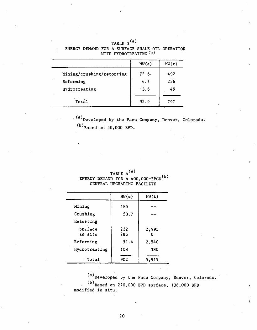
TABLE 3(a) ENERGY DEMAND FOR A SURFACE SHALE OIL OPERATION
WITH HYDROrREATING(b)
MW(e) MW(t)
Mining/crushing/retorting 72.6- 492
Reforming 6.7 256
Hydrotreating 13.6 49
Total 92.9 797
· (a)Developed by the Pace Company, D~nver, Colorado.
(b)Based on 50,000 BPD.
TABLE 4(a) - . ENERGY DE~Ul~ FOR A 400,000-BPCD{b)
CENTRAL UPGRADING FACILITY
Mining
Crushln~
Retorting
·surface In situ
Reforming
Hyd ro_t rea t ing
Total
Ml-1 (e)
185
50.7
222 286
51.4
108
902
MW(t)
2,995 0
2,540
380
5,915
(a)Developed by the Pace Company, Denver, Colorado.
(b)Based on 270,000 BPD surface, 138,000 BPD modified in situ.
20

•
suited to the production of kerogen from low-grade shales and involves
retorting with hot hydrogen.
In situ retorting with steam is now being investigated and appears
to o'ffer considerable potential for HTGR use if the process is shown
to be commercially viable. This operation involves the injection
of 10 MPa (1500 psig), 538°C (1000°F) steam into the oil shale
formation to retort the kerogen in place. An economical source of
steam will be a critical factor in the overall viability of the process.
The use of an HTGR would supply steam at the desired conditions,
allowing a considerable savings of fossil fuels, and could also
provide hydrogen for upgrading of the product.
The use of superheated steam as the heating medium in surface
retorts is an old con~ept, but little testing has been conducted.
Preliminary data from laboratory experiments Jndicate several advantages
for this process:
• Operating (retorting) tem?eratures are reduced [427°-454°C
versus 510°C (800°-850°F versus 950°F)].
e A better quality oil is produced (lower pour point, higher .
API gravity).
• Gas volumes are doubled with a greater percentage of
hydrogen in the gas (50%-60%).
The energy cost of producing steam has been the major drawback in
further developing the concept. The use of superheated ste~m produced
from an HTGR could be beneficial in advancing the development of this
technol?gy.
21

ALTERNATE HEAT TRANSMISSION AND STORAGE SYSTEMS
The high-temperature capability of the HTGR-PH enables it to be
coupled to several possible energy transport media for transport over
long distances and still provide go~d thermodynamic efficiency at
the user end. Several transport fluids and systems have been examined.
One is a chemical energy ~ystem wherein an endothermic reaction
(steam-methane reforming) takes place at the NHS t:!ml al"td an exothermic
reaction (methanation) at the user end. A second is the use of a
sensible heat salt system that is heated to 540°C (1000uF) at the
reactor end and transported to the user. The cooled salt is returned
to the reactor. This system has the potential for relatively inexpen
sive energy storage and may be useful for electric power peaking
applications (Ref. 1 ). A third system would be a direct· steam line
to the users if distances are not too long. Additional information
comparing these systems can be found in Ref. 2.
HYDROGEN PRODUCTION BY CLOSED-LOOP THERMOCHEMICAL PROCESS
Extensive development work is proceeding in the U.S. and abroad
on hydrogen processes that utilize a series of chemical steps tu
separate water into hydrogen and oxygen by thermal means. Most of
these processes need a high-temperature heat input step, which often is
the decomposition of sulfuric acid. The sulfur-iodine process for
thermochemical watersplitting is under development at General Atom~c
(Refs. 3, 4). A bench-scale unit demonstrating all the major steps
in this process has been constructed and is presently operating.
Watersplitting methods, when coupled to an NHS, pro~ide a way
of more than doubling synfuel production from a fixed quantity of
fossil feedstock. These savings occur since none of the fossil
source is used to provide heat for the process and no co2 is produced
in the hydrogen production process itself. In the longer term,
hydrogen is a likely candidate for replacement of current liquid and
gaseous fuels.
22
,.
..

C)
•.
•..
·'
..
CONCLUSIONS
1. The current U.S. energy picture promises a bright future for
synfuel .programs based on coal. Process development plans are
being firmed up, and demonstration-size plants should be started
in the near future~ A second-gen~ration plant could be nuclear
powered.
2. · Current analysis of the inclusion of HTGRs in the synfuel program
shows a major advantage in coal savings and enyironmental impact
and a moderate cost ~dvantage at present U.S. coal prices.
3 •
4.
In oil shale recovery, the HTGR-PH could be used in aboveground • I
retorting processes. A 50,000-BPD facility will require about
800 ~~(t) and 93 MW(e) if the kerogen is upgraded at the· site.
Energy distribution systems such as a sensible heat salt system
or a chemical energy system provide a new way of using nuclear
heat for existing industrial needs.
5. A conceptual design for the HTGR-PH plant at 850°C (1562°'F). core
outlet temperature for steam-methane reforming applications has
been developed based on General Atomic steam cycle and gas tur
bine work. For some applications, notably coal gasification by
steam-carbon reactions and thermochemical watersplitting, a core
outlet temperature of 950°C (1742°F) ls probably required .
23
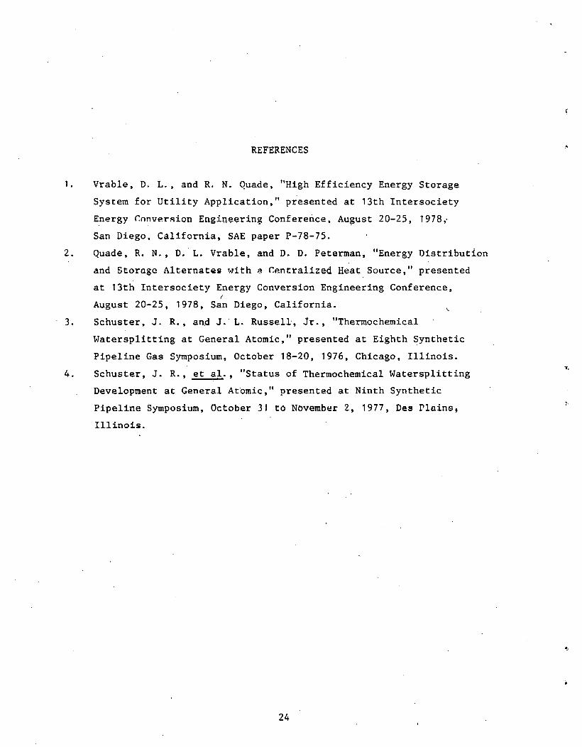
REFERENCES
1. Vrable, D. L .• and R. N. Quade, "High Efficiency Energy Storage
System for Utility Application," presented at 13th Intersociety
Energy r.nnvP.rsion Enginee~ing Conference, August 20-25, 1978,.
San Diego. California, SAE paper P-78-JS.
2. Quade. R. N., D. L. Vrable, and D. D. Peterman, "Energy Distribution
and Storage AlternatQ!il ~o1ith ~ r.entralized Heat Source," presented
at 13th Intersociety Energy Conversion Engineering Conference, r
August 20-25, 1978, San Diego, California.
3. Schuster, J. R., and J. L. Russell, Jr., "Thermochemical
Watersplitting at General Atomic," presented at Eighth Synthetic
Pipeline Gas Symposium, October 18-20, 1976, Chicago. Illinois.
4. Schuster, J. R., et al., "Status of Thermochemical Watersplitting
Development at General Atomic," presented at Ninth Synthetic
Pipeline Symposium, October 31 to Novemb~r 2, 1977, Des Plains,
Illinoh.
24
..

----KJENERALATOMIC::. __ _
GENERAL ATOMIC COMPANY P. 0. BOX 81608
SAN DIEGO, CALIFORNIA 92138