high technology medical devices 1 - med essence guide.pdf · high technology medical devices 1 |...
TRANSCRIPT

High Technology Medical Devices 1 | Sreznevského 17, 831 03 Bratislava, Slovakia Tel: +421 2 446 409 77; Mobile: +421 948 610 228, +421 903 114 944; Mail: [email protected]; Web: www.onkocet.eu
2 |
INSTRUCTIONS FOR USE (USER’S GUIDE) 1. GENERAL INDICATIONS
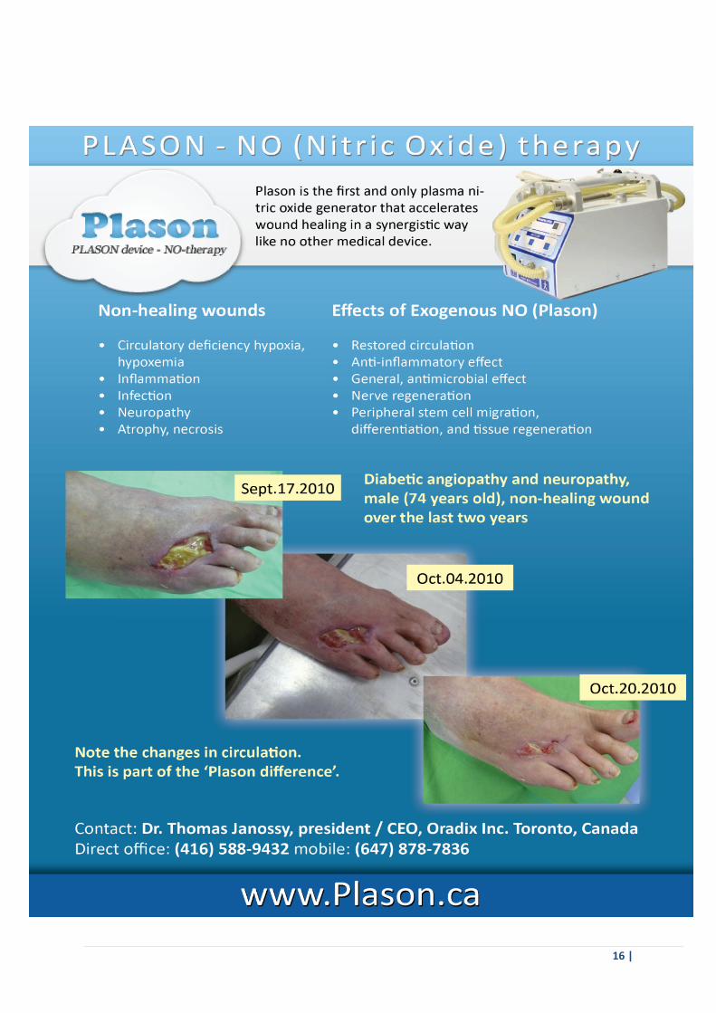
1.1. As the basis of the action of the Air‐plasma scalpel‐coagulator‐stimulator “PLASON” (subsequently ‐ apparatus) is
assumed the action on the tissue of the human organism of the flow of air plasma for obtaining of surgical effect and flow of gas, formed by cooling the air plasma and which contains the molecules of the mono‐oxide of nitrogen, for obtaining the therapeutic effect.
1.2. Present passport is intended for the medical personnel, which accomplishes operation, and engineering personnel,
which conducts maintenance and repair of apparatus.
1.3. Apparatus is the restorable article and in the case of malfunction undergoes routine repair. 1.4. To the operation of apparatus can be allowed medical personnel after the study of the order of preparation for the
work and the work of apparatus, presented in the present passport. 1.5. The use of an apparatus during the application of combustible anesthetics is inadmissible. 2. DESIGNATION
2.1. Apparatus is intended for coagulation and sterilization of wound surfaces, evaporation and destruction of
nonviable cloths and pathologic formations, dissection of biological tissues by plasma flow with the temperature to 4000°C, and also for the stimulation of reparative processes during the treatment of wounds, trophic ulcers, bedsores, sharp and chronic inflammatory processes, scar and sclerous changes, other defeats of the external covers of soft tissues, mucous membranes and internal organs by gas flow with the temperature to 40°C, which contains the mono‐oxide of nitrogen (NO), in the conditions of surgical departments.
3. TECHNICAL SPECIFICATIONS
3.1. The overall dimensions of apparatus correspond to the values, indicated in the figure. 3.2. The mass of apparatus with the equipment does not exceed 7,5 kg. The electric power supply of apparatus is
achieved from the network of alternating current with a voltage of 230 V with a frequency of 50 Hz 3.4. The power, consumed by apparatus, does not exceed 500 V∙A. 3.5. Apparatus it works change by manipulators, who ensure the regimes of coagulation, destruction and therapeutic
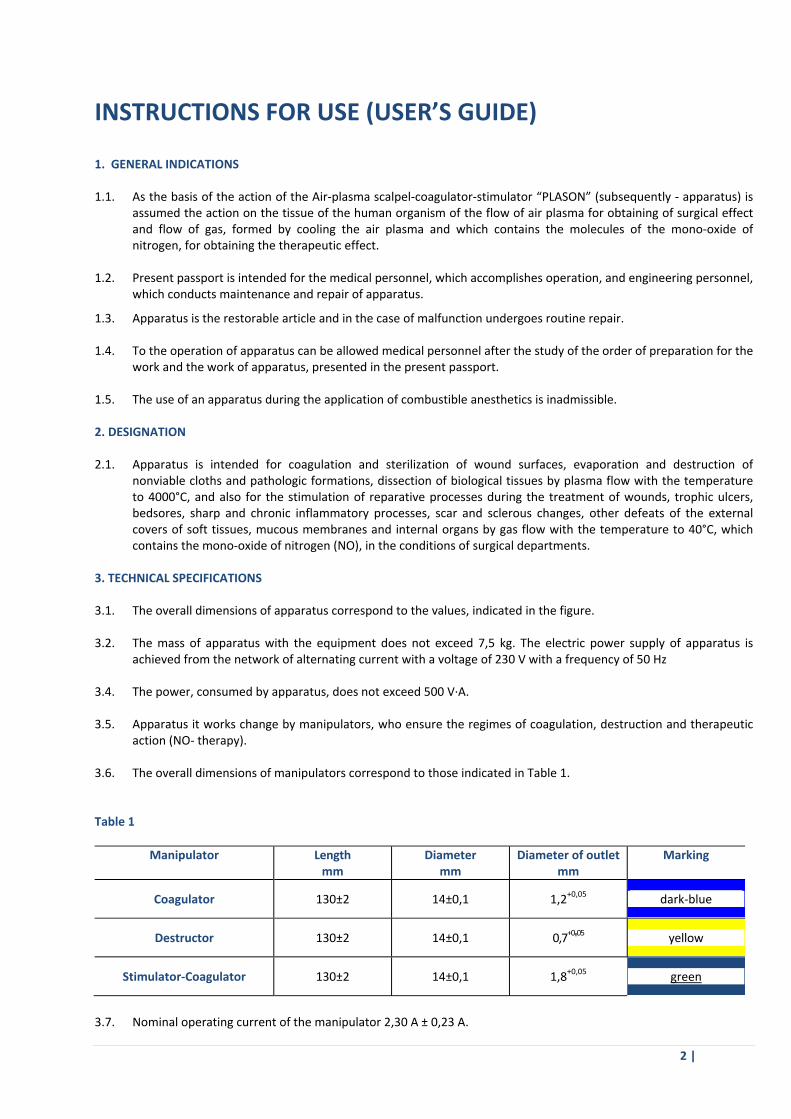
action (NO‐ therapy). 3.6. The overall dimensions of manipulators correspond to those indicated in Table 1. Таble 1
Manipulator Length mm
Diameter mm
Diameter of outlet mm
Marking
Coagulator 130±2 14±0,1 1,2+0,05 dark‐blue
Destructor 130±2 14±0,1 0,7+0'05 yellow
Stimulator‐Coagulator 130±2 14±0,1 1,8+0,05 green
3.7. Nominal operating current of the manipulator 2,30 A ± 0,23 A.

3 |
3.8. Time of establishment of manipulator operating conditions on the command “LAUNCHING” is not more than 5 s.
3.9. The device ensures work in the flow of 4 hours in the intermittent service. Time of operation ‐ 5 min., pause ‐ 1
min.
3.10. With the engaging of the device the key “NETWORK” is illuminated. On the selected regime of manipulator work
illumination of one of the buttons signals, which corresponds to the selected flow rate of air (Min, Norma, Max)
3.11. On the safety the apparatus corresponds to requirements GOST R 50267.0‐92 (EN 60601‐1) class the I with the
working part of the type B.
3.12. The device is resistant to the mechanical actions in operation by GOST R 50444‐92 (national standard) for group 2.
3.13. The device with the operation is resistant to the action of climatic factors by GOST R 15150‐69 (national standard)
for the form of the climatic performance UKhL of category 4.2
3.14. The device in the packing of manufacturing concern is resistant to the climatic actions during the transportation
and the storage by GOST 15150‐69 (national standard) for the conditions for storage 5.
3.15. The device in the transport packing is resistant to the mechanical actions with the transportation and possesses
vibration strength and shockproof quality by GOST R 50444‐92 (national standard) for group 2.
3.16. The external surfaces of apparatus and manipulators are resistant to the disinfection in accordance with the
requirements MU ‐287‐113 (national standard)/
3.17. The device on the possible consequences of failure relates to the class B by GOST R 50444‐92 (national standard).
3.18. Mean operating time of apparatus to the failure ‐ is not less than 1000 hours.
3.19. Average life to the writing off of apparatus ‐ is not less than 5 years. The criterion of limiting condition is
impossibility or the economic inexpediency of the restoration of apparatus.
3.20. The time, necessary for replacing the manipulator ‐ is not more than 5 min.
3.21. The electrical installation of apparatus corresponds to requirements RDT 25.106‐88 (national standard).
3.22. The device corresponds to requirements of electromagnetic compatibility GOST R 50267.0.2‐2005 (EN 60601‐1‐2).
3.23. Metallic and nonmetallic mineral coatings ‐ by GOST 9.303‐84 (national standard) for the group of operating
conditions 1 GOST 15150‐69 (national standard).
3.24. Paint and varnish coats ‐ GOST 9.032‐74 (national standard) for the operating conditions UKhL 4 GOST 9.104‐79
(national standard). Coatings of external surfaces ‐ not lower than the III class by GOST 9.032‐74 (national
standard).
3.25. The level of the acoustic power at a distance of 1,0 m of the outline of apparatus does not exceed 65 dBA.
3.26. The temperature of the external parts of the apparatus, which do not have contact with the patient, accessible for
the touching with the normal operation, does not exceed 55ºC.
3.27. Class of apparatus depending on the potential risk of application ‐ 2a by GOST R 51609‐2000 (Annex IX of the
Directive 93/42/EEC).

4 |
4. DELIVERY SET
4.1. The delivery set of apparatus corresponds to that indicated in table 2. Таble 2
№
Designation Designation of the document Quantity, pieces
1. 2. 3. 4. 5. 6. 7. 8. 9.
10.
11.
12.
Air‐plasma scalpel‐coagulator‐stimulator “PLASON”
Set of the equipment Coagulator Destructor Generator‐ stimulator Spacer Gas‐tube Tip 130 mm Key
Pedal Transporting trunk
Operational documentation
Passport Description of medical technology on CD
КРЛД 38642.001.
КРЛД 38642.001.07.
КРЛД 38642.001.08.
КРЛД 38642.001.09.
КРЛД 38642.001.11.
КРЛД 38642.001.12.
КРЛД 38642.001.14.
КРЛД 38642.001.15.
КРЛД 38642.001.16 .
КРЛД 38642.001 ПС
1 2 1 2 1 1 1 1 1 1 1 1
5. DEVICE, OPERATING PRINCIPLE AND THE REGIMES OF THE WORK OF THE APPARATUS
5.1. Construction of apparatus. The device consists of the service block (SB), electro‐hydropneumatic (EHP) supply, change manipulators, silicone
tube with the metallic tip and foot pedal. SB is structurally executed in the rectangular metal housing, which consists of two parts ‐ lower and upper. The lower part of the housing consists of horizontal base, front and rear panels and serves for the installation of all systems, which ensure the work of manipulator.
They are located on the front panel:
‐ key “NETWORK” with the illumination; ‐ button “START” and “STOP” with the illumination for start and disconnection of the manipulator; ‐ button “MIN”, “NORMA”, “MAX” with the illumination for the step control of the air flow rate; ‐ the hinged conclusion EHP of the supply; ‐ threaded carbine for the connection of silicone tube with the metallic tip; ‐ nest for the connection of the pedal.
Two brackets for the coil of net cable are located on the rear panel and special key for replacing the manipulator is fixed.
5 |
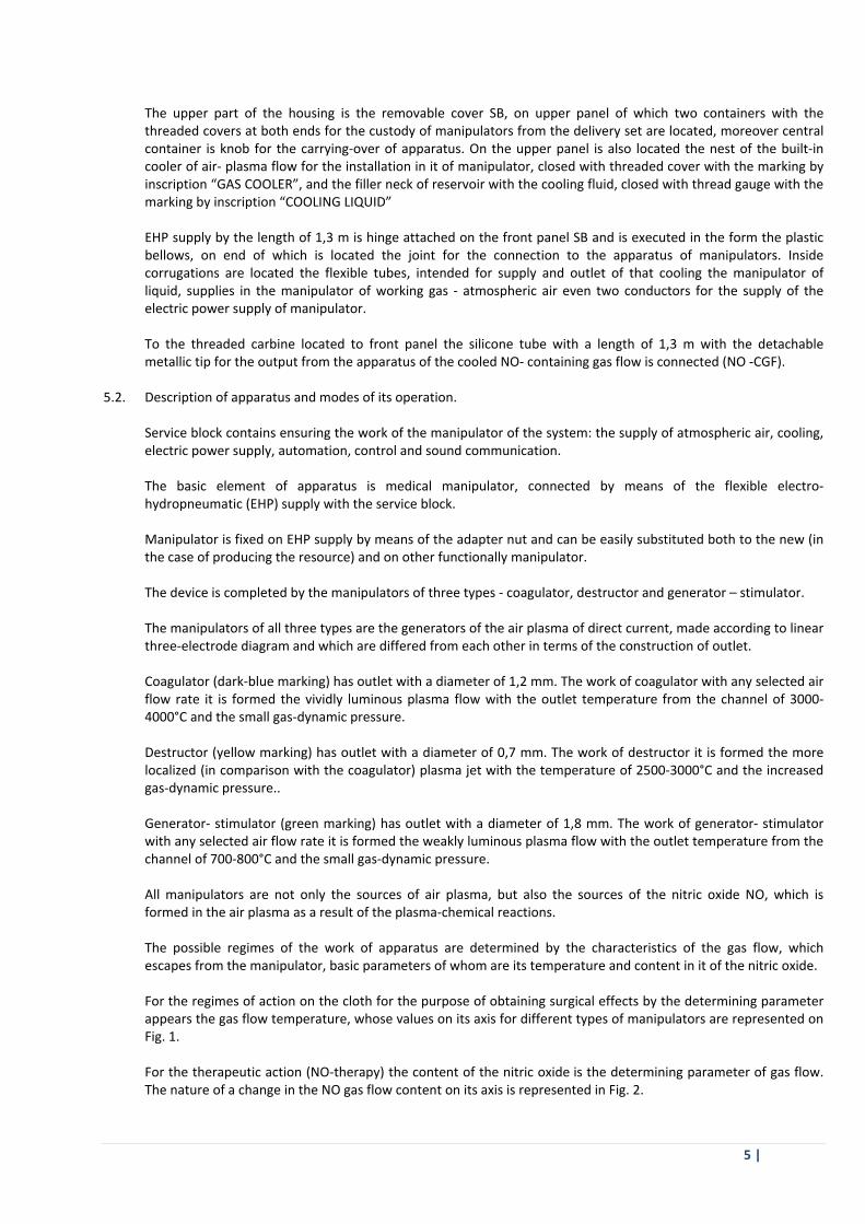
The upper part of the housing is the removable cover SB, on upper panel of which two containers with the threaded covers at both ends for the custody of manipulators from the delivery set are located, moreover central container is knob for the carrying‐over of apparatus. On the upper panel is also located the nest of the built‐in cooler of air‐ plasma flow for the installation in it of manipulator, closed with threaded cover with the marking by inscription “GAS COOLER”, and the filler neck of reservoir with the cooling fluid, closed with thread gauge with the marking by inscription “COOLING LIQUID”
EHP supply by the length of 1,3 m is hinge attached on the front panel SB and is executed in the form the plastic
bellows, on end of which is located the joint for the connection to the apparatus of manipulators. Inside corrugations are located the flexible tubes, intended for supply and outlet of that cooling the manipulator of liquid, supplies in the manipulator of working gas ‐ atmospheric air even two conductors for the supply of the electric power supply of manipulator.
To the threaded carbine located to front panel the silicone tube with a length of 1,3 m with the detachable
metallic tip for the output from the apparatus of the cooled NO‐ containing gas flow is connected (NO ‐CGF). 5.2. Description of apparatus and modes of its operation. Service block contains ensuring the work of the manipulator of the system: the supply of atmospheric air, cooling,
electric power supply, automation, control and sound communication. The basic element of apparatus is medical manipulator, connected by means of the flexible electro‐
hydropneumatic (EHP) supply with the service block. Manipulator is fixed on EHP supply by means of the adapter nut and can be easily substituted both to the new (in
the case of producing the resource) and on other functionally manipulator. The device is completed by the manipulators of three types ‐ coagulator, destructor and generator – stimulator. The manipulators of all three types are the generators of the air plasma of direct current, made according to linear
three‐electrode diagram and which are differed from each other in terms of the construction of outlet. Coagulator (dark‐blue marking) has outlet with a diameter of 1,2 mm. The work of coagulator with any selected air
flow rate it is formed the vividly luminous plasma flow with the outlet temperature from the channel of 3000‐4000°C and the small gas‐dynamic pressure.
Destructor (yellow marking) has outlet with a diameter of 0,7 mm. The work of destructor it is formed the more
localized (in comparison with the coagulator) plasma jet with the temperature of 2500‐3000°C and the increased gas‐dynamic pressure..
Generator‐ stimulator (green marking) has outlet with a diameter of 1,8 mm. The work of generator‐ stimulator
with any selected air flow rate it is formed the weakly luminous plasma flow with the outlet temperature from the channel of 700‐800°C and the small gas‐dynamic pressure.
All manipulators are not only the sources of air plasma, but also the sources of the nitric oxide NO, which is
formed in the air plasma as a result of the plasma‐chemical reactions. The possible regimes of the work of apparatus are determined by the characteristics of the gas flow, which
escapes from the manipulator, basic parameters of whom are its temperature and content in it of the nitric oxide. For the regimes of action on the cloth for the purpose of obtaining surgical effects by the determining parameter
appears the gas flow temperature, whose values on its axis for different types of manipulators are represented on Fig. 1.
For the therapeutic action (NO‐therapy) the content of the nitric oxide is the determining parameter of gas flow.
The nature of a change in the NO gas flow content on its axis is represented in Fig. 2.

6 |
Depending on the arrangement of manipulators, established on EHP supply, apparatus it makes it possible to realize two groups of the modes of operation (Fig. 3). The first group of regimes ‐ regimes with the free expiration from the manipulators of air‐ plasma flow, in this case apparatus is in state A on Fig. 3, and manipulator is retained in the hand of user.
The second group of regimes ‐
regimes of action on the biological tissue by the completely cooled (to room temperature) NO‐ containing gas flow, for obtaining which any manipulator is put into the nest of the built‐in cooler and the supply NO ‐CGF to the biological tissue is achieved through the silicone tube with the established at its end metallic tip with a diameter of the outlet of 0,7 mm (state of apparatus B in Fig. 3). For the check of functioning of manipulators the apparatus is supplied with the system of the sound communication, which forms the first sound signal during the establishment of the assigned regime of the work of manipulator and the shorter sound signals after every 60 it flogged the work of manipulator. For maintaining the stable thermal condition of manipulators the apparatus is supplied with the closed liquid system, which ensures their effective cooling and heat rejection into the surrounding space by means of two radiators and fans through the rear panel of apparatus.
Temperature and content of the nitrogen oxide in it are the basic physical chemistry flow parameters (NO). The temperature of expiration for destructor and coagulator com‐poses ~4000°C, and for the simulator‐coagulator ‐ ~1000°C (Fig. 1).
The temperature of flow is rapidly reduced with the removal from the outlet of manipulator and at a distance 100 mm does not exceed 100°C. The content of nitrogen oxides on the axis of gas flow represented in Fig. 2. It should be noted that the molecule of the nitrogen oxide possesses active oxidation potential and in the air medium enters into the reaction with molecular oxygen with the formation of chemically resistant compound ‐ the nitrogen dioxide (NO2), which as a result of this will always be present in the NO‐containing gas flow. The application of the standardized generator part of all manipulators makes it possible to obtain flows with the identical axial content of the nitrogen oxide, what also shown in Fig. 2. Range of the obtained concentrations NO is very wide ‐ from 2500 ppm to zero. This makes it possible to select those parameters, which it considers most acceptable for doctor.

7 |
The analysis of dependence of temperature and content of the nitrogen oxide on the axis of gas flow shows that the apparatus allows the enormous field of possibilities on the combining of the thermo‐physical and biochemical factors of
action on the biological tissues and objects for the user.
Coagulation of the wound
surfaces Coagulation is achieved by bringing the high‐temperature air‐plasma flow (HPF) directly to the wound surface. The temperature of flow in the region of contact must be not less than 2000°C, therefore, distance from the outlet of manipulator‐coagulator to the region of action must be not more than 25 mm. At the first moment of time (Fig. A) during bringing of energy HPF with the temperature more than 2000°C to the biological tissue its heating to the boiling point of woven liquid occurs. Compact layer of necrosis (CLN), which consists of the degradation products of protein connections is formed, partially damaged and nonviable, but preserved their structure cells (55°C), and the zone of paranecrosis ‐ zone of the partially reversible changes in the cells. Subsequently the zone of paranecrosis becomes the source of regeneration.
8 |
Further increase in the time of action (Fig. B) leads to strengthening of the process of boiling and evaporating the woven liquid. The spongy layer of necrosis (SLN) is formed ‐ the porous, elastic and airtight structure, which consists of the dehydrated protein and fatty connections. Clearly expressed physical boundary of the evaporation of liquid appears in the cloth, which divides the spongy (SLN) and compact (CLN) layers of necrosis (100°C). Upper temperature boundary of the spongy layer of necrosis coincides with the temperature of the beginning of the thermal decomposition of protein and fatty compounds into the simplest chemical elements (550°C, Fig. C). Above SLN is formed the carbonized (carbon) layer of necrosis (CaLN), which is the burnt and charred cloth. Qualitative hem‐aero‐lymph‐cholestasis is determined by the positive dynamics of shaping of the compact and spongy layers of necrosis or by the low rate of shaping of the carbon layer of necrosis. The thermo‐physical and geometric parameters of the plasma flow of coagulator are optimized so that reliable hem‐aero‐lymph‐cholestasis is reached on any biological cloths and at any speeds of counter blood flow. The significant (about 200 m/s) discharge velocity of hot gas from the outlet of coagulator creates condition on the surface of the coagulated section of the cloth, with which coagulation layers are formed directly from cloth itself, but not of the counter‐flows of the liquid, for example, of the blood or lymph entering. A change in the time of action and distance from the outlet of coagulator to the region of coagulation is the universal method of the dosage of the energy necessary for the coagulation. For obtaining the reliable coagulation the distance from the outlet of manipulator lies within the limits from 2 to 25 mm.
ATTENTION! In practice hem‐aero‐Iymph‐cholestasis can be achieved also without completeshaping of the entire region of thermal changes. Coagulation effect begins, for example, and without the formation of the carbon laver of necrosis.
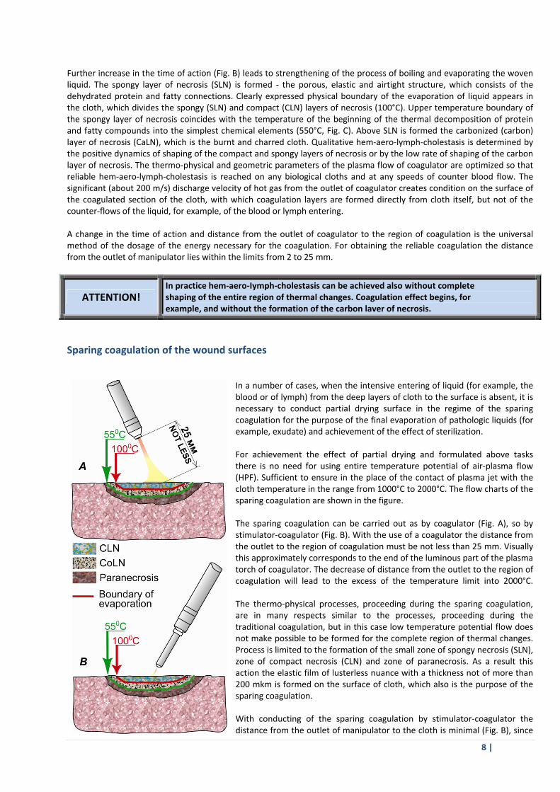
Sparing coagulation of the wound surfaces
In a number of cases, when the intensive entering of liquid (for example, the blood or of lymph) from the deep layers of cloth to the surface is absent, it is necessary to conduct partial drying surface in the regime of the sparing coagulation for the purpose of the final evaporation of pathologic liquids (for example, exudate) and achievement of the effect of sterilization. For achievement the effect of partial drying and formulated above tasks there is no need for using entire temperature potential of air‐plasma flow (HPF). Sufficient to ensure in the place of the contact of plasma jet with the cloth temperature in the range from 1000°C to 2000°C. The flow charts of the sparing coagulation are shown in the figure. The sparing coagulation can be carried out as by coagulator (Fig. A), so by stimulator‐coagulator (Fig. B). With the use of a coagulator the distance from the outlet to the region of coagulation must be not less than 25 mm. Visually this approximately corresponds to the end of the luminous part of the plasma torch of coagulator. The decrease of distance from the outlet to the region of coagulation will lead to the excess of the temperature limit into 2000°C. The thermo‐physical processes, proceeding during the sparing coagulation, are in many respects similar to the processes, proceeding during the traditional coagulation, but in this case low temperature potential flow does not make possible to be formed for the complete region of thermal changes. Process is limited to the formation of the small zone of spongy necrosis (SLN), zone of compact necrosis (CLN) and zone of paranecrosis. As a result this action the elastic film of lusterless nuance with a thickness not of more than 200 mkm is formed on the surface of cloth, which also is the purpose of the sparing coagulation. With conducting of the sparing coagulation by stimulator‐coagulator the distance from the outlet of manipulator to the cloth is minimal (Fig. B), since

9 |
the temperature of the escaping flow does not exceed 1000°C. This way, if it is necessary to realize the sparing coagulations on large surface it is possible to use a coagulator, and if it is necessary to coagulate the bounded spaces ‐ stimulator‐coagulator.
ATTENTION! For obtaining uniform coagulative membrane it is necessary to constantly change the angle of the tilting of plasma flow about the wound surface according to its relief.
Technology of conducting the sessions of NO‐therapy by coagulator and by destructor
Any manipulator for the action with the exogenous nitrogen oxide on the biological subjects, the cloth and pathologic centers makes it possible to use universality of generator parts. Temperature factor is fundamental physical limitation for applying the technology of NO‐therapy as a whole. The optimum temperature of action is determined by the following conditions: 1) by the absence of the possibility of the thermal damages of cellular structures; 2) by the absence of the sensations of thermal discomfort in patient. As practice shows, the temperature of the influencing flow of 40±10°C is optimal. This, on one side, less than the temperature of the beginning of the denaturing of protein connections, and, from the other side, creates pleasant sensation of blowout by warm air by the patient. Minimum distance from the outlet to the object, with which it is possible to carry out the sessions of the NO‐therapy by coagulator
or by destructor, is 150 mm. The flow chart of conducting the sessions of NO‐therapy is shown in the figure. The NO‐containing gas flow (NO‐CGF) is directed to surface desirably at right angle. Bright luminescent spot on the surface (optical and geometric projection of the outlet of manipulator on the workable surface) helps user to determine the center of flow and to direct him in the necessary direction. In this case in the region of the contact of flow with the cloth stationary circular region with the increased content of the nitrogen oxide is formed. Maximum concentration of NO is observed on the axis of gas flow and it falls to the periphery smoothly. Concentration of NO and NO2 on the centerline of gas flow is determined by the physical chemistry flow parameters (temperature and the content of oxides of nitrogen ‐ fundamental characteristics of the air‐plasma flows). The effective scope diameter of the workable surface NO ‐ CGF can be estimated according to the simple formula:
4
mm object, ther tomanipulato ofoutlet from Distance diameter Scope
If the geometric dimensions of the workable region or object are greater, the scope diameter, working they conduct by the scanning rectilinear or circular motions with a speed of the displacement of the zone of the increased concentration of approximately 0,5‐1,5 cm/s.

10 |
www.onkocet.eu
ATTENTION! The diameter of luminescent spot is lower than the diameter of the seizure of the workablesurface. Luminescent spot makes it possible only correctly direct the center of the air flow, which contains the nitrogen oxide.
ATTENTION! With conducting of sessions NO‐therapy by coagulator or by destructor it is necessary maximally attentively to supervise distance from the outlet of manipulator to the region of working for the exception of the possibility of causing the thermal damages.
Technology of conducting the sessions of NO‐therapy by the stimulator‐coagulator
Stimulator‐coagulator as device with the part cooler connected to the generator generates the gas flow, which contains the nitrogen oxide, with temperature potential smaller than coagulator or destructor. With conducting of the sessions of NO‐therapy this circumstance makes it possible to draw the manipulator nearer to the biological subject and as a result, create higher concentration in the near‐surface layers. The flow chart of conducting the sessions of NO‐therapy by stimulator‐coagulator is shown in the Fig. A. According to the dependence of the content of the nitrogen oxide on the axis of flow minimum distance from the outlet to the surface, where the temperature will not exceed 40±10°C, is about 80 mm (temperature and the content of oxides of nitrogen ‐ fundamental characteristics of the air‐plasma flows). Directed desirably the right angle to the workable object flow will smoothly spread in parallel to surface, creating axisymmetrical region with the increased content of the nitric oxide. The center of luminescent spot will be indicated to user, where the flow is directed to the given moment. The effective scope diameter of the workable surface is tentatively defined as fourth of distance from the outlet of manipulator to the surface. For averting the possibility of putting the thermal damages the construction provides for installation to the stimulator‐coagulator of the detachable thermal spacer, whose application makes it possible to fix the physical chemistry parameters of flow (Fig. B). Thermal spacer is executed in the form of hollow cylinder with the wide lateral windows. Its length is selected in such a way that the temperature of the NO‐containing gas flow (NO‐CGF) on the end of spacer would compose 40±10°C, in this case the concentration of the nitrogen oxide will have a value of ~750 ppm. The installation of thermal spacer does not introduce changes in geometric parameters NO‐CGF. The effective scope diameter on the previous composes fourth from the distance and in the case of a maximally possible approximation of stimulator‐ coagulator with the thermal spacer to the workable object established on it composes ~20 mm.
11 |
ATTENTION! Because of possible heating thermal spacer at a continuous duty avoid mechanical contact spacer with biological tissues.
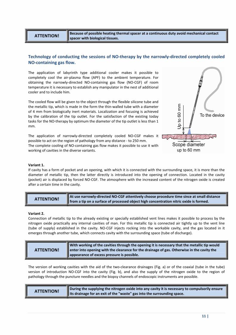
Technology of conducting the sessions of NO‐therapy by the narrowly‐directed completely cooled NO‐containing gas flow. The application of labyrinth type additional cooler makes it possible to completely cool the air‐plasma flow (APF) to the ambient temperature. For obtaining the narrowly‐directed NO‐containing gas flow (NO‐CGF) of room temperature it is necessary to establish any manipulator in the nest of additional cooler and to include him. The cooled flow will be given to the object through the flexible silicone tube and the metallic tip, which is made in the form the thin‐walled tube with a diameter of 4 mm from biologically inert materials. Localization and focusing is achieved by the calibration of the tip outlet. For the satisfaction of the existing today tasks for the NO‐therapy by optimum the diameter of the tip outlet is less than 1 mm. The application of narrowly‐directed completely cooled NO‐CGF makes it possible to act on the region of pathology from any distance ‐ to 250 mm. The complete cooling of NO‐containing gas flow makes it possible to use it with working of cavities in the diverse variants. Variant 1. If cavity has a form of pocket and an opening, with which it is connected with the surrounding space, it is more than the diameter of metallic tip, then the latter directly is introduced into the opening of connection. Located in the cavity (pocket) air is displaced by forced NO‐CGF. The atmosphere with the increased content of the nitrogen oxide is created after a certain time in the cavity.
ATTENTION! At use narrowly‐directed NO‐CGF attentively choose procedure time since at small distance from a tip on a surface of processed object high concentration nitric oxide is formed.
Variant 2. Connection of metallic tip to the already existing or specially established vent lines makes it possible to process by the nitrogen oxide practically any internal cavities of man. For this metallic tip is connected air tightly up to the vent line (tube of supply) established in the cavity. NO‐CGF injects rocking into the workable cavity, and the gas located in it emerges through another tube, which connects cavity with the surrounding space (tube of discharge).
ATTENTION! With working of the cavities through the opening it is necessary that the metallic tip would enter into opening with the clearance for the drainage of gas. Otherwise in the cavity the appearance of excess pressure is possible.
The version of working cavities with the aid of the two‐clearance drainages (Fig. a) or of the coaxial (tube in the tube) version of introduction NO‐CGF into the cavity (Fig. b), and also the supply of the nitrogen oxide to the region of pathology through the puncture needles and the biopsy channels of endoscopic instruments are possible.
ATTENTION! During the supplying the nitrogen oxide into any cavity it is necessary to compulsorily ensure its drainage for an exit of the "waste" gas into the surrounding space.

12 |
Destruction (dissection) Basic difference in the manipulator ‐destructor from the coagulator ‐ diameter of outlet (coagulator 1,2 mm, destructor 0,7 mm). This constructive solution makes it possible to aggravate and to concentrate energy of air‐ plasma flow (APF) and, furthermore, to increase the speed of its expiration. In working of living biological tissues concentrated and aggravated APF of destructor the carbon layer of necrosis is heated to the temperature of ~800°C and it begins to be decomposed into the small particles ‐ to sublimate, and high‐speed flow takes away (exhausting) decay products CoLN from the zone of action. With this dynamics the carbon layer of necrosis ceases to be natural heat shield as in the case of coagulator, and entire structure of the region of thermal changes is moved into the depths of the cloth. As a result, a zone of the destructured cloths is formed, surrounded by the coagulation layer, which ensures reliable hemostasis. Effective distance from the outlet of manipulator must be smallest possible. This makes it possible to obtain qualitative section with putting of smallest possible damages to the adjacent cloths and to organs.
ATTENTION! During destruction or dissection of the walls of hollow organs the danger of the damage of their internal surfaces as a result of the penetration through the incision of hot gas can arise.
Technology of obtaining antiseptic solution on the basis of hydrogen peroxide and nitrogen oxide (solution of Aleksandrov M.T.)
For obtaining the antiseptic solution on the basis of hydrogen peroxide and nitrogen oxide it is necessary to dissolve the specific quantity of NO in 3% solution of hydrogen peroxide. The low solubility of the nitrogen oxide in the aqueous solutions does not make it possible to prepare this solution without the application of technology of bubbling. Flow chart is shown in the figure. In the transparent capacity is filled the fixed quantity 3% of solution of hydrogen peroxide. Through the tightly closed cover of capacity the metallic tip of the supply of the NO‐containing gas flow (NO‐CGF) is introduced, so that the outlet of tip would be located below liquid level in the capacity. Additionally in the cover of higher than liquid level vent line for connecting the space of capacity with the atmosphere free from the liquid is established. With the engaging of the apparatus "PLASON" NO‐CGF it enters directly into 3% solution of hydrogen peroxide in the form of bubbles, saturating peroxide by the nitrogen oxide. The optimum time for the preparation of solution depends on the volume of the prepared solution and is determined by the formula:
t = 0,06∙ V
where the V is volume of the solution in ml, t ‐ time of bubbling in min.
The obtained solution can be used in the therapeutic process immediately or in the course of 20 days under the condition for its storage in the cool, protected from the light place.
ATTENTION! Obtaining solution with the described technology must be conducted in the exhaust hood or in a room equipped with exhaust ventilation.
For the control of quantity and flow rate of the cooling fluid in the cooling system of manipulators the apparatus is supplied with the system of the sound communication, which forms the appropriate sound signals with the presence of disturbances or malfunctions in the cooling system.

13 |
For the remote control of the start and of the disconnection of manipulators in the delivery set of apparatus enters the pedal, which works on the retention.
6. INDICATIONS ON SECURITY MEASURES
6.1. To use apparatus it follows after thorough study and with a strict observance of requirements, presented in the
present passport. 6.2. To work only with the proper apparatus and the manipulators. With the failure detection it is necessary to direct
apparatus toward the checking. 6.3. The operation of apparatus in the case of applying the combustible anesthetics is forbidden. 6.4. In connection with the fact that apparatus adapts in the accommodations, to which is extended the action “of the
rules of the device of the electrical devices” V –1b (division UPZ), its connections to the electrical network must be achieved through the protection from short circuit (automatic switches, safety devices).
6.5. It is forbidden to exploit apparatus with the taken cover of service block. 6.6. Before conducting of surgical interventions with the aid of the apparatus the surgeon is obligated to become
acquainted with the action of plasma flow on soft tissues by trial actions on the damp meat. 6.7. With the work with the switch on manipulators should be observed special caution. 6.7.1. With the work with the device it is strictly forbidden to substitute different objects under the plasma flow. 6.7.2. Continuous operation of the device is possible only in the premises, supplied with exhaust ventilation.
7. ORDER OF INSTALLATION AND THE PUTTING INTO COMMISSION 7.1. To extract apparatus from the transport packing. 7.2. To verify the completeness of apparatus. 7.3. To establish apparatus to the horizontal surface. Arrangement must be selected in such a way as to ensure free
access to the control elements and convenient observation of them. 7.4. To connect to the apparatus foot pedal.
8. PREPARATION OF APPARATUS FOR THE WORK
8.1. Apparatus is delivered to user in the completely assembled form with that established on flexible EHP supply by
coagulator (dark‐blue marking). The preparation of apparatus for the work consists in checking of its fitness for work with different manipulators with different operating modes on the air flow rate.
8.2. To ascertain that the net rosette has a contact of grounding. In the case of its absence to ensure the installation of
net rosette with the grounded contact. 8.3. To set key “NETWORK” into the initial state ‐ position “0”. 8.4. To include the fork of the cable of the nourishment of apparatus in the rosette of the supply voltage 230 V of 50
Hz with the permissible current is not less than 6 A. 8.5. To include apparatus via the transfer of key “NETWORK” from the position “0” to the position “I”. In this case is
included the illumination of key “NETWORK”, buttons “STOP” even by one of control knobs of expenditure “MIN”, “NORMA” or “MAX”, pump and cooling‐system fans of apparatus begin to work.

14 |
8.6. By pressure on the button “MAX” to establish the maximum air flow rate. 8.7. To produce the start of coagulator by pressure on the button “LAUNCHING”. About the normal work of apparatus
and coagulator testifies the start of the illumination of button “LAUNCHING”, the presence of sound signal and expiration from the outlet of the coagulator of steady plasma torch.
8.8. By pressure on the button “min” to establish the minimum air flow rate. The air flow rate through the coagulator
must decrease, about which a decrease in gas‐dynamic pressure of the escaping plasma flow testifies. 8.9. To turn off manipulator by pressure on the button “STOP”. 8.10. To turn off apparatus via the transfer of key “NETWORK” from the position “I” to the position “0”. 8.11. To remove coagulator with EHP of supply, after turning away the adapter nut, which connects manipulator and
underwater if necessary for this possibly the use of a special key, fixed on the rear wall of apparatus. 8.12. To establish on EHP the supply of destructor (yellow marking), after screwing the adapter nut to the support.
Before the installation of manipulator to the joint in the case of the presence on the joint of the tracks of moisture to wipe through with his gauze napkin.
8.13. For the functional test of apparatus and destructor to repeat actions in sequence 8.5‐8.10. 8.14. To put on EHP supply generator‐ stimulator (green marking), after carrying out actions in sequence 8.11, 8.12. 8.15. For the functional test of apparatus and generator‐ stimulator to repeat actions in sequence 8.5‐8.10. 8.16. For the functional test of the device in the regime of remote control to produce the start of any manipulator by
pressure on the pedal. illumination of button “LAUNCHING”, the presence of sound signal and expiration from the outlet of the manipulator of steady plasma torch testify about the normal work of apparatus.
8.17. To let go pedal. In this case must occur the disconnection of manipulator and the passage of apparatus into the
state on p. 8.5. 8.18. To produce the disinfection of the external surfaces of apparatus and manipulators by five‐fold working, each of
whom consists of two rubbings of external surfaces with the napkin, moistened by 3% by solutions of hydrogen peroxide by GOST 177‐88 (national standard) with the addition of the cleaning agent by GOST 25644‐96 (national standard) or by 1% by solution of chloramine by technical specifications TU 9392‐031‐00203306‐2003.
8.19. Apparatus is ready to operation. 8.20. During the intra‐operating application of an apparatus on EHP supply should be put on sterile sleeve from kh/b
cloth or turned up the supply into the sterile sheet (towel). The sterilization of manipulators should be carried out by chemical gas methods by ethylene oxide or by formaldehyde. Is possible the sterilization of manipulators in UV or gas‐formalin camera, and also by rubbing with different solutions with the subsequent turning up of manipulator into the sterile napkin
The moistening of manipulators is not allowed!
9. OPERATIONAL PROCEDURE
9.1. To set key “NETWORK” into the initial state ‐ position “0”. 9.2. To insert the plug of the device power supply in the socket with 230 V voltage of 50 Hz with the permissible
current 6 A.
15 |
9.3. To select and to establish on EHP supply necessary for the work manipulator. 9.4. To include apparatus via the transfer of key “NETWORK” from the position “0” to the position “I”. 9.5. By pressure on the button “MIN”, “NORMA” or “MAX” to establish the necessary for the work air flow rate. 9.6. To produce the start of manipulator by pressure on the button “LAUNCHING” or by pressure and by the retention
of foot pedal. 9.7. To carry out the necessary surgical or therapeutic manipulations. 9.8. To turn off manipulator by pressure on the button “STOP” or by release of foot pedal. 9.9. To turn off apparatus via the transfer of key “NETWORK” from the position “I” to the position “0”. 9.10. To take out the fork of the cable of the nourishment of apparatus from the rosette of net nourishment. This point
is carried out at the discretion of the service personnel.
9.11. In the interruptions between the therapeutic actions (procedures) is recommended to produce the disconnection of manipulator and not to turn off the device by the “NETWORK” key to the end of the outlined cycle of procedures.
This point is carried out at the discretion of user.
9.12. For the transfer of the device into operating the position B one should remove the threaded cover (marking “THE COOLER OF GAS”), which closes the nest of the built‐in cooler on the upper panel of apparatus, put into the nest any manipulator and slightly harvest to it for the fixation of manipulator in the elastic sealing element of cooler.
One should fasten the taken threaded cover on the screw holder, located on the rear bracket of the knob of the device opposite the built‐in cooler of gas.
9.13. The transfer of the device of the working order A into the working order B and vice versa must be produced only
with the turned‐off manipulator.
10. THE MAINTENANCE
10.1. For guaranteeing the reliable work of apparatus to conduct timely maintenance. 10.2. To follow the cleanliness of apparatus and manipulators. External surfaces of apparatus and manipulators to disinfect on p. 8.18. present passport. 10.3. To conduct daily maintenance with the regular work with the apparatus. 10.4. Monthly maintenance with the regular operation of apparatus is carried out by medical personnel, which exploits apparatus. 10.5. Annual servicing of apparatus with the regular work with it to carry out not less than one time per year. 10.5.1. To open apparatus from the network, to remove the cover of service block. 10.5.2. To clean dust from internal volume of apparatus, using vacuum cleaner. 10.5.3. To look around thoroughly installation, paying attention to the presence of clearances between the components, the exterior view of the elements of installation, the integrity of wire insulation, fastening units. After inspection to gather apparatus. 10.5.4. Periodic annual maintenance is carried out by the specially prepared operating personnel.
16 |

High Technology Medical Devices 17 | Sreznevského 17, 831 03 Bratislava, Slovakia Tel: +421 2 446 409 77; Mobile: +421 948 610 228, +421 903 114 944; Mail: [email protected]; Web: www.onkocet.eu