high tech aquarium ecology 3155 - tunze.com · this water level regulator comprises a controller,...
TRANSCRIPT

1
GebrauchsanleitungInstructions for UseMode d’emploi x3155.8888
08/2017
Osmolator® 3155
Hig
h Te
ch A
quar
ium
Eco
logy

2 3
InhaltAllgemeinesLieferform / FunktionSicherheitshinweisePlatzwahl ControllerPlatzwahl der SensorenMontieren der ElastikpufferBefestigung der Sensoren mit Magnet HolderBefestigung mit Universal- HalterHalterung an Glasscheibe kleben Strom- und WasseranschlüsseBefestigung des ZulaufschlauchesVorratsbehälterController 5017Inbetriebnahme in UnterschrankanlagenDie Sensoren - Schaltpunkt und PflegeZubehörErsatzteileGarantieStörungenEntsorgung
Seite46
8-1012
14-2022
24-2628-30
323436
38-4042-46
4850-52
5456-57
5860-66
68
Page57
9-1113
15-2123
25-2729-31
333537
39-4143-47
4951-53
5556-57
5961-67
68
Page57
9-1113
15-2123
25-2729-31
333537
39-4143-47
4951-53
5556-57
5961-67
68
Table of ContentsGeneral aspectsCondition delivered / functionSafety instructionsPositioning the controllerPositioning the sensorsFitting the elastic absorbersAttaching the sensors using a magnet holderAttachment using a universal holderSticking the holding device on the glass pane Power and water connectionsAttachment of the feed hoseStorage tankController 5017Initial operation in aquarium cabinetsThe sensors – switching point and servicingAccessoriesSpare partsGuaranteeFailuresDisposal
SommaireGénéralitésContenu - fonctionsSécurité d’utilisationPlacement ControllerPlacement des capteursMontage des tampons élastiquesFixation des capteurs avec Magnet HolderFixation des capteurs avec support universelFixation par collageRaccordements hydrauliques et électriquesFixation du tuyau d’amenée d’eauRéservoirsController 5017Mise en service en filtrations sous aquariumCapteurs, points de fonctionnementAccessoiresPièces de rechangeGarantieQue faire si… ?Gestion des déchets
TUNZE® Aquarientechnik GmbHSeeshaupter Straße 6882377 PenzbergGermanyTel: +49 8856 2022Fax: +49 8856 2021www.tunze.com Email: [email protected]
Hig
h Te
ch A
quar
ium
Eco
logy

4 5
Allgemeines Der TUNZE Osmolator® 3155 (1) wird zur Sicherung der osmotischen Stabilität in Süß- und Meerwasseraquarien eingesetzt. Er gewährleistet den genauen und sicheren Ausgleich des verdunsteten Wassers.Dieser Wasserstandsregler enthält einen Controller, zwei Sensoren, zwei Magnet Holder für Sensoren und zahlreiches Zubehör. Er ist geeignet zur Platzierung in Unterschrank-Filteranlagen, in Comline-Filter oder unmittelbar am Rand des Aquariums. Der Magnet Holder für zwei Sensoren (1) ist für eine Glasstärke bis 15mm, der Magnet Holder für separaten Sicherheitssensor (2) für eine Glasstärke bis 12mm geeignet.
Dieses Gerät ist für Benutzer (einschl. Kinder) mit eingeschränkten physischen, sensorischen oder psychischen Fähigkeiten bzw. ohne jegliche Erfahrung oder Vorwissen nur dann geeignet, wenn eine angemessene Aufsicht oder ausführliche Anleitung zur Benutzung des Gerätes durch eine verantwortliche Person sichergestellt ist.Achten Sie darauf, dass Kinder nicht mit dem Gerät spielen (3).
General aspects TUNZE Osmolator® 3155 (1) is used to ensure the osmotic stability in freshwater and saltwater aquariums. It guarantees the accurate and safe compensation of evaporated water.This water level regulator comprises a controller, two sensors, two magnet holders for sensors and numerous accessories. It is suitable for use in cabinet filter plants, in Comline filters or directly on the edge of the aquarium. The Magnet Holder for two sensors (1) is suitable for a glass thickness of up to 15mm (1/2“), and the Magnet Holder for the separate safety sensor (2) for a glass thickness up to 12mm (3/8“).
This device is suitable for users (including children) with limited physical, sensorial or mental abilities or without any experience or previous knowledge only, if a suitable supervision or detailed instructions on the operation of the device is assured by a responsible person. Please make sure that children do not play with the device (3).
Généralités L’Osmolator® TUNZE® 3155 (1) est conçu pour assurer la stabilité osmotique d’un aquarium d’eau douce ou d’eau de mer par une compensation fiable et précise de l’eau évaporée. Cette régulation de niveau comporte un Controller, deux capteurs de niveau, deux supports magnétiques pour capteurs et de nombreux accessoires. L’Osmolator® est conçu pour un placement dans les filtrations sous aquariums, les filtres Comline® ou directement au bord de la cuve. Le support magnétique à deux capteurs (1) est prévu pour une épaisseur de vitre jusqu’à 15mm, le support magnétique à un seul capteur (2) jusqu’à 12mm.
Les utilisateurs (enfants inclus) ayant des limitations physiques, sensorielles, psychiques, ne bénéficiant pas d’une expérience ou de connaissances suffisantes ne peuvent utiliser cet appareil qu’avec le concours d’une tierce personne responsable, assurant la surveillance ou veillant à l’observation du mode d’emploi. Veuillez vous assurer que des enfants ne puissent jouer avec cet appareil (3).

6 7
Lieferform Der Osmolator® ist einbaufertig mit Netzteil (1), Dosierpumpe (2), Schlauch (3), Spannhalter (4), Magnet Holder für zwei Sensoren (5) und Magnet Holder für separaten Überlaufsensor (6). Funktion Im TUNZE Osmolator® 3155 sind zwei Sensoren eingesetzt, d.h. ein Arbeitssensor (7) zur Überwachung des Wasserniveaus und ein Sicherheitssensor (8) gegen Überfüllung des Aquariums. Der Arbeitssensor tastet die Wasseroberfläche ab und initiiert bei Unterschreitung des eingestellten Wasserniveaus den Controller (9). Dieser schaltet die Dosierpumpe (2) ein, die soviel Wasser aus dem Vorratsbehälter ins Aquarium fördert, bis die verdunstete Wassermenge ersetzt ist. Danach schaltet der Controller mit elektronischer Zeitüberwachung die Dosierpumpe automatisch ab. Sollte aus technischen Gründen der Arbeitssensor versagen, verhindert der Sicherheitssensor das Überfüllen des Aquariums und es ertönt ein Signalton. Läuft die Dosierpumpe länger als 10 Min. wird sie zur Sicherheit abgeschaltet.Bei Aquarien über 1.000L empfehlen wir aufgrund der hohen Verdunstung, statt der Dosierpumpe 5000.02 die Schaltsteckdose 3150.11 (10) mit Rückförderpumpe Silence 1073.02 oder 1073.04 zu verwenden.
Delivery condition The Osmolator® is ready for installation with the power supply (1), metering pump (2), hose (3), clamp (4), Magnet Holder for two sensors (5) and the Magnet Holder for the separate overflow sensor (6). Functions There are two sensors implemented into the TUNZE Osmolator 3155®, whereas an operating sensor (7) is used to monitor the water level and a safety sensor (8) to prevent an overfilling of the aquarium. The operating sensor scans the water surface, and triggers the controller (9) if the water level falls below the preset water threshold. This switches on the metering pump (2), which then conveys a sufficient amount of water from the reservoir into the aquarium to replenish the evaporated water. After this process has concluded, the controller which is equipped with an electronic time monitoring, automatically switches off the metering pump. The operating sensor should fail due to technical reasons, the safety sensor will prevent an overfilling of the aquarium, and a signal tone will be emitted. If the metering pump runs longer than 10 minutes it will be shut off for safety reasons.Due to the high rate of evaporation in aquariums with more than 1,000l (264 USgal.) we recommend the use of the switched socket outlet 3150.11 (10) with the recirculation pump Silence 1073.02 or 1073.04 instead of the metering pump 5000.02.
Contenu L’Osmolator® est livré prêt à l’emploi avec alimentation secteur (1), pompe de dosage (2), tuyau d’amenée (3), support (4), Magnet Holder à deux capteurs (5) et Magnet Holder pour capteur anti-débordement séparé (6). Fonctions L’Osmolator® TUNZE® est équipé de deux capteurs: un capteur de niveau précis (7) et un capteur de sécurité anti-débordement (8). Le capteur de niveau effectue un contrôle précis du niveau réel de l’eau en relation avec le Controller (9). Lors d’une baisse de niveau d’eau, le Controller enclenche la pompe de dosage (2) placée dans le réservoir jusqu’à la compensation totale de l’eau. Si pour une raison technique le capteur de régulation devait être défectueux ou si la pompe de dosage devait ne plus s’arrêter, le deuxième capteur de sécurité évitera un débordement de l’aquarium et actionnera une signalisation lumineuse et sonore. Si le temps de fonctionnement de la pompe de dosage dépasse 10 minutes, la pompe est automatiquement stoppée avec une signalisation.En raison du volume d’évaporation des aquariums de plus de 1.000L, nous conseillons l’utilisation de la prise commandée 3150.11 (10) avec pompe de reprise Silence 1073.02 ou 1073.04 à la place de la pompe de dosage 5000.02.

8 9
Sicherheitshinweise Osmolator® nur im Aquarium einsetzen, der Betrieb im Freien ist nicht zulässig.Netzteil 5012.01 und Controller 5017 nur an trockener und gut belüfteter Stelle anbringen! (1)Nicht in die Nähe von Heiz- und Wärmequellen aufstellen (2), Umgebungstemperatur max. + 35°C.Kabel nicht knicken (3).Arbeitssensor nicht Infrarot- oder HQI-Licht aussetzen. Spitze immer nach unten einsetzen, sonst Störung durch starkes Licht möglich.Magnetscheibenreiniger oder andere Magnetfelder nicht in unmittelbare Nähe des Sicherheitssensors bringen, sonst Funktionsstörung möglich (4).Vor Inbetriebnahme prüfen, ob Betriebsspannung mit Netzspannung übereinstimmt. Dosierpumpe nicht ohne Wasser betreiben (5).Bei Reinigung und Wartung Netzstecker vom Controller 5017 ziehen. Beschädigte Kabel nicht reparieren, sondern Geräte zur Reparatur geben.Nicht an Fremdgeräte anschließen (6). Während der Verwendung von Wasserwechselgeräten Osmolator® abschalten.Gebrauchsanleitung gut aufbewahren.
Safety instructions Only use the Osmolator® for indoor aquariums, since an outdoor operation is not permitted.Only position the power supply 5012.01 and controller 5017 in a dry and well ventilated place! (1)Do not place it near heat sources of any kind (2), ambient temperature max. +35°C.Do not fold the cable (3).To not expose the operating sensor to infrared or HQI light. Always insert the pointed side downwards, because otherwise interference from strong light could be possible.Do not place the magnetic glass cleaners or other magnetic fields into the immediate vicinity of the safety sensor, since otherwise malfunctions could occur (4).Before commissioning, check that the operating voltage corresponds to the mains voltage. Do not operate the metering pump without water (5).During cleaning and maintenance disconnect the mains plug from the controller 5017. Do not repair damaged cables, instead have the devices repaired.Do not connect to external devices (6). Switch off the Osmolator® during the use of water exchange devices.Keep the instruction manual in a safe place.
Sécurité d’utilisation N’utilisez l’Osmolator® qu’en aquarium, une utilisation hors habitation est interdite.Positionnez l’alimentation 5012.01 et le Controller 5017 en un endroit sec et bien aéré (1).Ne positionnez pas les appareillages près d’une source de chaleur (2), température max. +35°C.Ne pliez pas les câbles (3).N’exposez pas le capteur de régulation aux HQI. Pour éviter des perturbations dues à des sources lumineuses intenses, positionnez toujours la pointe du capteur vers le bas.Afin d’évitez un défaut de fonctionnement, n’approchez pas d’aimant de nettoyage ou d’autre source magnétique près du capteur de sécurité (4).Avant toute mise en fonction, vérifiez la compatibilité de l’alimentation avec le réseau électrique.Evitez un fonctionnement à sec de la pompe de dosage (5).Pour tout entretien, déconnectez l’alimentation du Controller 5017. Ne réparez pas un câble endommagé mais renvoyez tout l’appareil en réparation.N’utilisez aucun appareillage étranger (6). Déconnectez l’Osmolator® durant les opérations de changement d’eau. Veuillez consulter attentivement la notice d’entretien.

10 11
Sicherheitshinweise Magnet Holder Achtung, sehr starker Magnet! (1)
Magnet Holder von Kindern fernhalten! Achtung Verletzungsgefahr! (2)
Magnethälften nicht direkt zusammenbringen! Die Magnethälften haften mit ca. 25 - 50kg, je nach Typ bei direktem Kontakt (3).
Magnetteile mit der Hand nur an den Seitenflächen greifen; niemals die Hand oder Finger zwischen die Kontaktflächen bringen!
Magnet zieht Metallteile und andere Magneten unter 10cm Abstand mit großer Kraft an! Beim Hantieren mit dem Magnet sollten sich keine Metallteile, andere Magneten, Klingen oder Messer im Umkreis von 10cm befinden, um Verletzungen zu vermeiden.
Vorsicht bei magnetisch empfindlichen Gegenständen, z.B. Herzschrittmachern, Datenträger, Kreditkarten und Schlüssel, mind. 30cm Abstand halten!
Beim Transport des Magnet Holders immer das mitgelieferte Styroporstück verwenden.
Erhitzung über 50°C führt zur Zerstörung des Magneten, bzw. Verlust der Magnetwirkung.(4)
Safety instructions for Magnet Holder Caution - very strong magnet ! (1)Keep Magnet Holder out of reach of children ! Caution ! Danger of injury ! (2)Do not bring upper and lower magnet part together directly ! Depending on the type, the parts of the magnet cling together on direct contact with about 25 to 50kg (55 to 110 lbs.)(3).Get hold of the magnet parts at the sides only; never get your hand or fingers between the contract surfaces !Attracts metal parts and other magnets with a large force at a distance of below 10cm (3.9 in.) ! When handling the magnet, no metal parts, other magnets, blades or knives should be located closer than 10cm (3.9 in.) in order to avoid injuries. Exercise caution in case of magnetically sensitive objects, such as pacemakers, data carriers, credit cards and keys – keep a distance of at least 30cm (11.8 in.) !Always use the piece of polystyrene supplied when transporting the Magnet Holder.Heat of more than 50° Celsius (122° F) will lead to the destruction of the magnet or the loss of the magnetic action. (4)
Sécurité d’utilisation Magnet Holder Attention, aimants surpuissants ! (1)
Les aimants sont à tenir hors de portée des enfants! Attention, risques de blessures ! (2)
Ne jamais réunir directement les deux parties des aimants ! Force d’attraction env. 25 - 50kg en fonction du modèle et lors du contact direct (3).
Tenir les aimants uniquement sur les côtés sans jamais intercaler la main ou les doigts entre les surfaces magnétiques !
Les aimants attirent fortement le métal ferreux et les autres aimants à moins de 10cm de distance ! Pour éviter les blessures lors de la manipulation des aimants, aucune partie métallique, aimant, lame ou couteau ne doivent se trouver à moins de 10cm.
En présence d’appareillages sensibles comme des simulateurs cardiaques, des supports de données, des cartes de crédits et des clés, observez une distance minimale de 30cm !
Lors du transport de Magnet Holder, utilisez toujours la cale en polystyrène livrée dans l’emballage. Un échauffement de plus de 50°C conduit à l’altération des aimants et à une perte de leur puissance magnétique (4).
CAUTION!
12 13
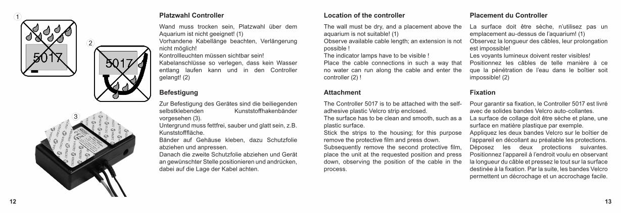
Platzwahl Controller Wand muss trocken sein, Platzwahl über dem Aquarium ist nicht geeignet! (1)Vorhandene Kabellänge beachten, Verlängerung nicht möglich!Kontrollleuchten müssen sichtbar sein!Kabelanschlüsse so verlegen, dass kein Wasser entlang laufen kann und in den Controller gelangt! (2)
Befestigung Zur Befestigung des Gerätes sind die beiliegenden selbstklebenden Kunststoffhakenbänder vorgesehen (3).Untergrund muss fettfrei, sauber und glatt sein, z.B. Kunststofffläche.Bänder auf Gehäuse kleben, dazu Schutzfolie abziehen und anpressen.Danach die zweite Schutzfolie abziehen und Gerät an gewünschter Stelle positionieren und andrücken, dabei auf die Lage der Kabel achten.
Location of the controller The wall must be dry, and a placement above the aquarium is not suitable! (1)Observe available cable length; an extension is not possible !The indicator lamps have to be visible !Place the cable connections in such a way that no water can run along the cable and enter the controller (2) !
Attachment The Controller 5017 is to be attached with the self-adhesive plastic Velcro strip enclosed.The surface has to be clean and smooth, such as a plastic surface.Stick the strips to the housing; for this purpose remove the protective film and press down.Subsequently remove the second protective film, place the unit at the requested position and press down, observing the position of the cable in the process.
Placement du Controller La surface doit être sèche, n’utilisez pas un emplacement au-dessus de l’aquarium! (1)Observez la longueur des câbles, leur prolongation est impossible!Les voyants lumineux doivent rester visibles!Positionnez les câbles de telle manière à ce que la pénétration de l’eau dans le boîtier soit impossible! (2)
Fixation Pour garantir sa fixation, le Controller 5017 est livré avec de solides bandes Velcro auto-collantes.La surface de collage doit être sèche et plane, une surface en matière plastique par exemple.Appliquez les deux bandes Velcro sur le boîtier de l’appareil en décollant au préalable les protections.Déposez les deux protections suivantes. Positionnez l’appareil à l’endroit voulu en observant la longueur du câble et pressez le tout sur la surface destinée à la fixation. Par la suite, les bandes Velcro permettent un décrochage et un accrochage facile.

14 15
Platzwahl der Sensoren direkt im Aquarium Der Arbeitsensor ist in der Höhe am großen Magnet Holder einstellbar, damit kann die Distanz zwischen normalem Wasserstand (Level) und Sicherheitsabschaltung (Too high) genau eingestellt werden.(1) 20mm Schaltabstand(2) 29mm Schaltabstand
Einsatz am Aquarienrand ohne Abdeckung (3).Der Schaltabstand vom normalen Wasserstand (Level) bis zur Sicherheitsabschaltung (Too high) beträgt bei dieser Anbringung 20 bis 29mm je nach Einstellung (1) oder (2). Direkte Lichtstrahlung durch HQI-Leuchten und Nähe von Luftausströmern vermeiden, ein starker Algenwuchs kann die Funktionen stören!
Location of sensors directly in the aquarium The height of the operating sensor is adjustable on the large Magnet Holder, so that the distance between the normal water level (level) and safety shut-off (too high) can be adjusted precisely.(1) 20mm switching distance(2) 29mm switching distance
Usage on the rim of the aquarium without a cover (3).In this installation scenario, the switching distance of the normal water level (level) up to the safety shut-off (too high) is 20 to 29mm depending on the setting (1) or (2). Avoid a direct HQI light irradiation and a close proximity to air discharges, since a strong algae growth can interfere with the functionality!
Placement des capteurs directement dans l’aquarium Le capteur de régulation est réglable en hauteur sur le grand Magnet Holder, de ce fait la distance entre le niveau d’eau normal (Level) et le niveau de sécurité (Too high) est ajustable avec précision.(1) 20mm de différence(2) 29mm de différence Placement au bord de l’aquarium sans galerie (3).La différence entre le niveau normal (Level) et le niveau de sécurité (Too high) est ajustable de 20 à 29mm en fonction des réglages (1) ou (2). Evitez le placement direct à proximité d’une source HQI puissante ou d’un diffuseur d’air, une forte croissance d’algues sur les capteurs pourrait perturber leur fonctionnement!
20mm29mm
Too highLevel
16 17
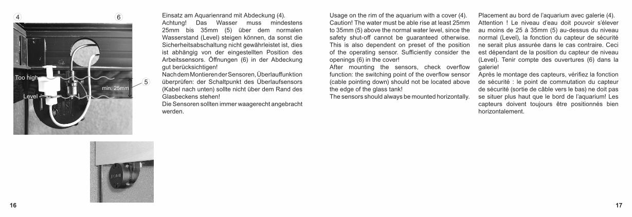
Einsatz am Aquarienrand mit Abdeckung (4).Achtung! Das Wasser muss mindestens 25mm bis 35mm (5) über dem normalen Wasserstand (Level) steigen können, da sonst die Sicherheitsabschaltung nicht gewährleistet ist, dies ist abhängig von der eingestellten Position des Arbeitssensors. Öffnungen (6) in der Abdeckung gut berücksichtigen! Nach dem Montieren der Sensoren, Überlauffunktion überprüfen: der Schaltpunkt des Überlaufsensors (Kabel nach unten) sollte nicht über dem Rand des Glasbeckens stehen!Die Sensoren sollten immer waagerecht angebracht werden.
Usage on the rim of the aquarium with a cover (4).Caution! The water must be able rise at least 25mm to 35mm (5) above the normal water level, since the safety shut-off cannot be guaranteed otherwise. This is also dependent on preset of the position of the operating sensor. Sufficiently consider the openings (6) in the cover! After mounting the sensors, check overflow function: the switching point of the overflow sensor (cable pointing down) should not be located above the edge of the glass tank!The sensors should always be mounted horizontally.
Placement au bord de l’aquarium avec galerie (4).Attention ! Le niveau d’eau doit pouvoir s’élever au moins de 25 à 35mm (5) au-dessus du niveau normal (Level), la fonction du capteur de sécurité ne serait plus assurée dans le cas contraire. Ceci est dépendant de la position du capteur de niveau (Level). Tenir compte des ouvertures (6) dans la galerie!Après le montage des capteurs, vérifiez la fonction de sécurité : le point de commutation du capteur de sécurité (sortie de câble vers le bas) ne doit pas se situer plus haut que le bord de l’aquarium! Les capteurs doivent toujours être positionnés bien horizontalement.
Too high
Levelmin. 25mm

18 19
Einsatz am Aquarienrand mit reduziertem Schaltabstand (7).Falls die zuvor beschriebenen Einsätze nicht möglich sind, sollte der Sicherheitssensor (mit Kabel nach unten) auf dem kleinen separaten Magnet Holder mit Sensorgehäuse (8) montiert werden. Der Schaltabstand zwischen beiden Sensoren kann dann in diesem Fall mind. 10mm erreichen. Wir empfehlen diesen Mindestabstand vom Sicherheitssensor (Too high) zu dem Arbeitssensor (Level) nicht zu unterschreiten, da sonst geringe Wasserschwankungen oder Wellen nach oben störend wirken können.Einstellung des Arbeitssensors in der Höhe am großen Magnet Holder gut berücksichtigen!
Bei dieser Montage taucht der Sicherheitssensor (mit Kabel nach unten) etwas in das Wasser ein und muss deshalb in Zeitabständen von rund drei Monaten regelmäßig gereinigt und auf Funktion geprüft werden.
Usage on the rim of the aquarium with a reduced switching distance (7).If the previously described operations are not possible, the safety sensor (with the cable pointing down) should be mounted on the small separate Magnet Holder with the sensor housing (8). In this case, the switching distance between two sensors can then be at least 10mm (.4 in.). We recommend not to underrun this minimum distance between the safety sensor (too high) and the operating sensor (level), because otherwise small upward fluctuations of the water level or waves can have a disruptive effect.Sufficiently consider the adjustment of the operating sensor in terms of height on the large magnetic holder!
For this type of assembly, the safety sensor (with the cable pointing down) is somewhat immersed in the water, and must therefore be cleaned and checked for functionality in regular intervals of approx. three months.
Placement au bord de l’aquarium avec une différence de déclenchement réduite (7). Si le montage décrit précédemment avec un seul Magnet Holder est imposssibe, il est nécessaire de monter le capteur de sécurité (sortie de câble vers le bas) sur le petit Magnet Holder pour un seul capteur (8). La différence de niveau de déclenchement entre les deux capteurs peut alors être réduite à 10mm. Nous conseillons de ne pas réduire plus encore la différence entre le capteur de régulation (Level) et de sécurité (Too high). Dans ce cas les moindres variations en surface pourraient déclencher régulièrement le capteur de sécurité.Attention à bien considérer la possibilité d’un réglage en hauteur du capteur de régulation sur le grand Magnet Holder!Avec ce montage, le capteur de sécurité (sortie de câble vers le bas) se trouve partiellement immergé, il sera nécessaire de le nettoyer régulièrement et de vérifier son fonctionnement tous les 3 mois.
Level
Too high
min.10mm

20 21
Platzwahl der Sensoren in Unterschrankfilter Bei Unterschrankanlagen mit mehreren Kammern oder eingetauchten Aquarienkammerfiltern müssen die Sensoren immer in die letzte Filterkammer mit Rückförderpumpe eingesetzt werden. Wir empfehlen den Sicherheitssensor (mit Kabel nach unten) auf dem kleinen Magnet Holder mit Sensorgehäuse zu befestigen (1) und den Arbeitssensor (mit Kabel nach oben) an dem großen Magnet Holder (2).Einstellung des Arbeitssensors in der Höhe am großen Magnet Holder beachten!Zugängliche Stelle im Filter wählen, nicht neben dem Wasserzulauf oder Pumpenauslauf platzieren! Der Sicherheitssensor sollte hoch genug über dem maximalen Wasserstand positioniert werden, so dass beim Stillstand der Rückförderpumpe kein Überlaufalarm ausgelöst wird.Empfehlung bei Meerwasser:Um eine Verkalkung des Arbeitssensors zu vermeiden, sollte er von einem Kalkwasserzulauf (Kalziumhydroxid) Abstand haben. Um eine vorzeitige Verkalkung vorzubeugen, sollte der Kalkwasserzulauf immer direkt ins Aquarium führen.
Location selection for the sensors when used with cabinet filters In aquarium cabinets with multiple chambers or submerged aquarium chamber filters, always insert the sensors into the last filter chamber with the return pump, see figure (3)! We recommend attaching the safety sensor (with the cable pointing down) onto the small Magnet Holder (1), and the operating sensor (with the cable pointing upwards) to the large magnetic holder (2).Sufficiently consider the adjustment of the operating sensor in terms of height on the large magnetic holder!Select a well accessible position in the filter, and do not place it next to the water inlet or pump discharge! The safety sensor should be positioned high enough above the maximum water level, so that an operation stop of the recirculation pump does not trigger an overflow alarm.Recommendation when using sea water:To avoid a calcification of the operating sensor, it should be located away from a lime water inlet (calcium hydroxide). To prevent a premature calcification, the lime water inlet should always be routed directly into the aquarium.
Placement des capteurs en filtrations sous aquarium Lors d’une intégration en cuves de filtration ou bacs à décantation à plusieurs compartiments, placez toujours l’Osmolator® dans le dernier compartiment comportant la pompe de reprise vers l’aquarium. Fixez le capteur de sécurité (sortie de câble vers le bas) sur le petit Magnet Holder pour un seul capteur (1) et le capteur de régulation (sortie de câble vers le haut) sur le grand Magnet Holder (2). Attention à bien considérer la possibilité d’un réglage en hauteur du capteur de régulation sur le grand Magnet Holder!Assurez-vous de la position optimale des capteurs, évitez le placement à proximité d’une descente d’eau ou d’une sortie de pompe! Placez le capteur de sécurité au-dessus du niveau d’eau et suffisamment haut pour qu’un arrêt de la pompe de reprise n’entraîne pas systématiquement une alarme! Conseils pour l’eau de mer :Afin d’éviter une calcification prématurée du capteur de régulation, il est nécessaire de l’éloigner d’un apport éventuel de Kalkwasser (hydroxyde de calcium). Pour éviter les dépôts calciques dans la cuve de filtration, il est indispensable que cet apport de Kalkwasser se fasse directement dans l’aquarium.
Too high
Level

22 23
Montieren der selbstklebenden Elastikpuffer Für eine maximale Haltekraft sollten die Magnet Holder immer mit selbstklebenden Elastikpuffern verwendet werden.
ACHTUNG! Magneten nacheinander einzeln vorbereiten und weit voneinander ablegen, sonst Verletzungsgefahr.
Elastikpuffer von Folie entfernen (1) und auf Klebestellen pressen (2). Für jedes Magnetteil 4 Stück verwenden. Die Klebestellen befinden sich wie in Bild (3) gezeigt an den hierfür vorgesehenen runden Vertiefungen.
Attaching the self-adhesive elastic buffers The magnetic holder always be used with self-adhesive elastic buffers to achieve the maximum holding power.
Caution ! Prepare magnets separate from each other, and place them far away from each other, as otherwise there is a danger of injury.
Remove the elastic buffers from the film (1) and press them on to the spot provided for the purpose (2). Use four units for each part of the magnet. As shown in the illustration (3), the adhesion points are in the round cavities provided for the purpose.
Montage des tampons élastiques autocollants Pour une adhérence maximale de Magnet Holder, il est impératif de monter les tampons élastiques sur les deux parties du support.
ATTENTION ! Procédez avec un seul aimant à la fois, tenez les aimants éloignés l’un de l’autre, risques de blessures.
Détachez le tampon élastique (1) de son carton puis pressez-le sur la surface de collage du support magnétique (2). Appliquez 4 tampons élastiques par support. Les surfaces de collages sont matérialisées par les renfoncements visibles sur la vue (3).

24 25
Befestigung beider Sensoren auf dem großen Magnet Holder, bis 15mm Glasstärke Sicherheitssensor (Kabel nach unten) auf der Halteplatte befestigen (1) und Kabel in die Kabelbefestigung drücken.Arbeitssensor (Kabel nach oben) einführen (2), danach bis Anschlag anheben und durch Drehen verriegeln.Geeigneten Platz an der Glasscheibe im Aquarium vorbereiten, sie sollte algenfrei sein und die Außenseite sollte trocken und sauber sein.Innenteil des Magnet Holders mit den Elastikpuffern in Richtung Glas an die Aquariumscheibe anbringen (3).Außenteil des Magnet Holders zum Innenteil halten (4) und nun vorsichtig zusammenbringen.Für eine Befestigung des großen Magnet Holders bis 20mm Glasstärke, siehe Zubehör.
Attachment of both sensors on the large Magnet Holder, up to a glass thickness of 15mm (1/2“). Attach the safety sensor (cable pointing down) to the mounting plate (1) and press the cable into the cable fastener.Insert the operating sensor (cable pointing upwards) (2), then lift upwards until the stop position is reached and lock it by turning.Prepare a suitable place on the glass pane, which is free of algae and the outside is clean and dry.Attach the inner part of the Magnet Holder to the aquarium glass (3) with the elastic buffer facing in the direction of the glass.Hold the outer part of the Magnet Holder towards the inner part (4) and then carefully bring them together.For an attachment of the large Magnet Holder up to a glass thickness of 20mm (3/4“) refer to the accessories.
Fixation des deux capteurs sur le grand Magnet Holder pour vitres jusqu’à 15mm d’épaisseur Fixez le capteur de sécurité (sortie de câble vers le bas) sur la plaque (1) et insérez le câble dans son support.Insérez le capteur de régulation (sortie de câble vers le haut) (2), tirez le capteur vers le haut jusqu’à butée et verrouillez par une courte rotation.Préparez l’emplacement sur la vitre. Celle-ci doit être sans algues dans l’aquarium, propre et sèche à l’extérieur.Appliquez la partie interne du Magnet Holder avec les tampons élastiques en direction du verre (3).Amenez avec précaution la partie externe du Magnet Holder face à la partie interne (4).Pour une fixation du grand Magnet Holder jusqu’à 20mm d’épaisseur de vitres, voir Accessoires.
26 27
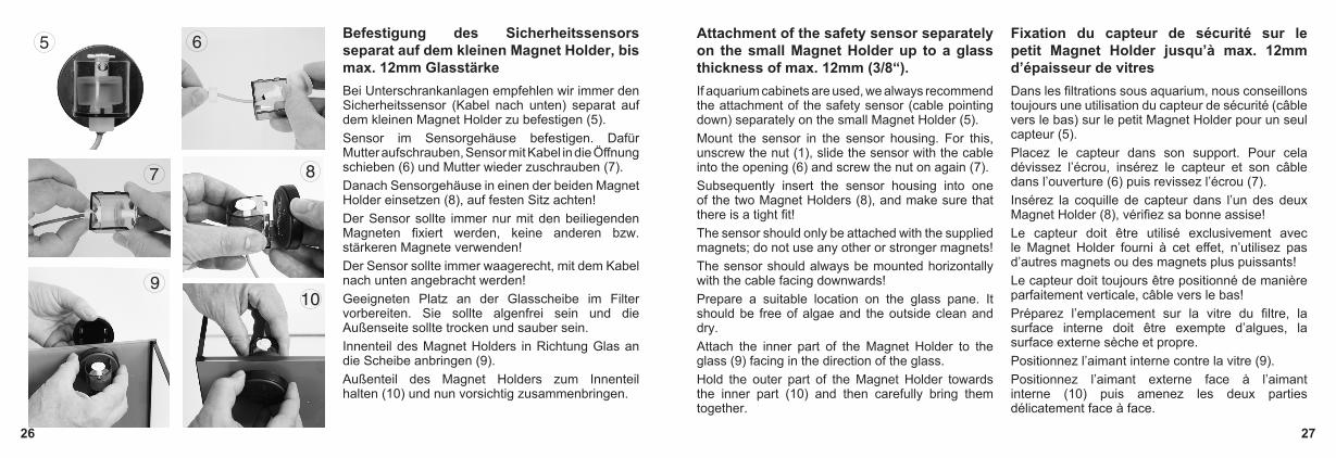
Befestigung des Sicherheitssensors separat auf dem kleinen Magnet Holder, bis max. 12mm GlasstärkeBei Unterschrankanlagen empfehlen wir immer den Sicherheitssensor (Kabel nach unten) separat auf dem kleinen Magnet Holder zu befestigen (5).Sensor im Sensorgehäuse befestigen. Dafür Mutter aufschrauben, Sensor mit Kabel in die Öffnung schieben (6) und Mutter wieder zuschrauben (7).Danach Sensorgehäuse in einen der beiden Magnet Holder einsetzen (8), auf festen Sitz achten!Der Sensor sollte immer nur mit den beiliegenden Magneten fixiert werden, keine anderen bzw. stärkeren Magnete verwenden!Der Sensor sollte immer waagerecht, mit dem Kabel nach unten angebracht werden!Geeigneten Platz an der Glasscheibe im Filter vorbereiten. Sie sollte algenfrei sein und die Außenseite sollte trocken und sauber sein.Innenteil des Magnet Holders in Richtung Glas an die Scheibe anbringen (9).Außenteil des Magnet Holders zum Innenteil halten (10) und nun vorsichtig zusammenbringen.
Attachment of the safety sensor separately on the small Magnet Holder up to a glass thickness of max. 12mm (3/8“).If aquarium cabinets are used, we always recommend the attachment of the safety sensor (cable pointing down) separately on the small Magnet Holder (5).Mount the sensor in the sensor housing. For this, unscrew the nut (1), slide the sensor with the cable into the opening (6) and screw the nut on again (7).Subsequently insert the sensor housing into one of the two Magnet Holders (8), and make sure that there is a tight fit!The sensor should only be attached with the supplied magnets; do not use any other or stronger magnets!The sensor should always be mounted horizontally with the cable facing downwards!Prepare a suitable location on the glass pane. It should be free of algae and the outside clean and dry.Attach the inner part of the Magnet Holder to the glass (9) facing in the direction of the glass.Hold the outer part of the Magnet Holder towards the inner part (10) and then carefully bring them together.
Fixation du capteur de sécurité sur le petit Magnet Holder jusqu’à max. 12mm d’épaisseur de vitresDans les filtrations sous aquarium, nous conseillons toujours une utilisation du capteur de sécurité (câble vers le bas) sur le petit Magnet Holder pour un seul capteur (5).Placez le capteur dans son support. Pour cela dévissez l’écrou, insérez le capteur et son câble dans l’ouverture (6) puis revissez l’écrou (7).Insérez la coquille de capteur dans l’un des deux Magnet Holder (8), vérifiez sa bonne assise!Le capteur doit être utilisé exclusivement avec le Magnet Holder fourni à cet effet, n’utilisez pas d’autres magnets ou des magnets plus puissants!Le capteur doit toujours être positionné de manière parfaitement verticale, câble vers le bas!Préparez l’emplacement sur la vitre du filtre, la surface interne doit être exempte d’algues, la surface externe sèche et propre.Positionnez l’aimant interne contre la vitre (9).Positionnez l’aimant externe face à l’aimant interne (10) puis amenez les deux parties délicatement face à face.
28 29
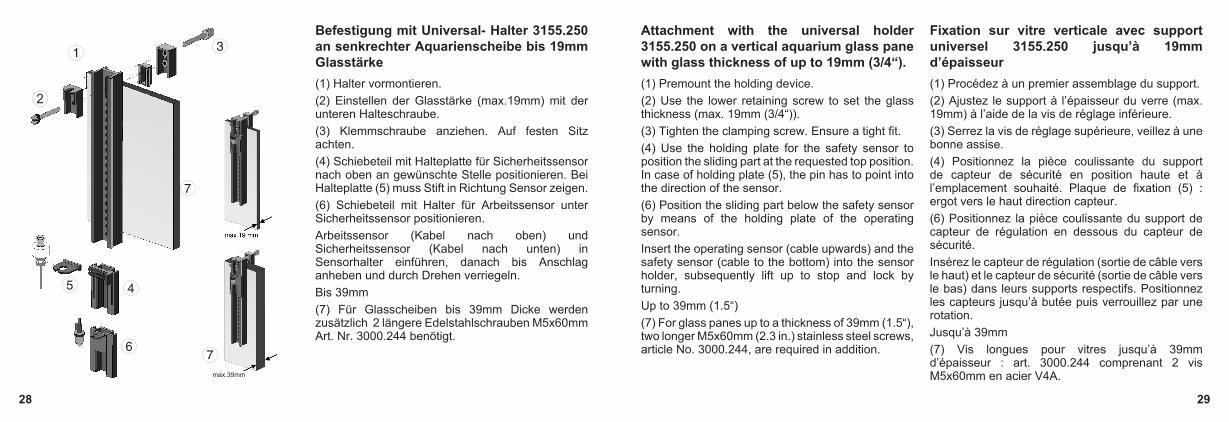
Befestigung mit Universal- Halter 3155.250 an senkrechter Aquarienscheibe bis 19mm Glasstärke (1) Halter vormontieren.(2) Einstellen der Glasstärke (max.19mm) mit der unteren Halteschraube.(3) Klemmschraube anziehen. Auf festen Sitz achten.(4) Schiebeteil mit Halteplatte für Sicherheitssensor nach oben an gewünschte Stelle positionieren. Bei Halteplatte (5) muss Stift in Richtung Sensor zeigen.(6) Schiebeteil mit Halter für Arbeitssensor unter Sicherheitssensor positionieren.Arbeitssensor (Kabel nach oben) und Sicherheitssensor (Kabel nach unten) in Sensorhalter einführen, danach bis Anschlag anheben und durch Drehen verriegeln.Bis 39mm(7) Für Glasscheiben bis 39mm Dicke werden zusätzlich 2 längere Edelstahlschrauben M5x60mm Art. Nr. 3000.244 benötigt.
Attachment with the universal holder 3155.250 on a vertical aquarium glass pane with glass thickness of up to 19mm (3/4“). (1) Premount the holding device.(2) Use the lower retaining screw to set the glass thickness (max. 19mm (3/4“)).(3) Tighten the clamping screw. Ensure a tight fit.(4) Use the holding plate for the safety sensor to position the sliding part at the requested top position. In case of holding plate (5), the pin has to point into the direction of the sensor.(6) Position the sliding part below the safety sensor by means of the holding plate of the operating sensor.Insert the operating sensor (cable upwards) and the safety sensor (cable to the bottom) into the sensor holder, subsequently lift up to stop and lock by turning.Up to 39mm (1.5“)(7) For glass panes up to a thickness of 39mm (1.5“), two longer M5x60mm (2.3 in.) stainless steel screws, article No. 3000.244, are required in addition.
Fixation sur vitre verticale avec support universel 3155.250 jusqu’à 19mm d’épaisseur (1) Procédez à un premier assemblage du support.(2) Ajustez le support à l’épaisseur du verre (max. 19mm) à l’aide de la vis de réglage inférieure.(3) Serrez la vis de réglage supérieure, veillez à une bonne assise.(4) Positionnez la pièce coulissante du support de capteur de sécurité en position haute et à l’emplacement souhaité. Plaque de fixation (5) : ergot vers le haut direction capteur.(6) Positionnez la pièce coulissante du support de capteur de régulation en dessous du capteur de sécurité.Insérez le capteur de régulation (sortie de câble vers le haut) et le capteur de sécurité (sortie de câble vers le bas) dans leurs supports respectifs. Positionnez les capteurs jusqu’à butée puis verrouillez par une rotation.Jusqu’à 39mm(7) Vis longues pour vitres jusqu’à 39mm d’épaisseur : art. 3000.244 comprenant 2 vis M5x60mm en acier V4A. max.39mm

30 31
Befestigung mit Universal- Halter 3155.250 an waagerechter Aquarienscheibe bis 19mm Glasstärke (1) Klemmhalter vormontieren.(2) Einstellen der Glasstärke (max.19mm) mit der Halteschraube.(3) Klemmschrauben anziehen.(4) Halteschiene mit Schiebeteil für Sicherheitssensor (5) vormontieren, dabei gewünschte Position des Sensors einstellen.(6) Schiebeteil für Arbeitssensor auf Halteschiene vormontieren, dabei gewünschte Position des Sensors einstellen.(7) Schraube und Mutter an Halteschiene lose befestigen, in Klemmhalter (1) einhängen und festschrauben.Arbeitssensor (Kabel nach oben) und Sicherheitssensor (Kabel nach unten) in Sensorhalter einführen, danach bis Anschlag anheben und durch Drehen verriegeln.Bis 39mm(8) Für Glasscheiben bis 39mm Dicke werden zusätzlich 2 längere Edelstahlschrauben M5x60mm Art. Nr. 3000.244 benötigt.
Attachment with the universal holder 3155.250 on a horizontal aquarium glass pane with glass thickness of up to 19mm (3/4“). (1) Premount the holding clamp.(2) Use the retaining screw to set the glass thickness (max. 19mm (3/4“)).(3) Tighten the clamping screws.(4) Premount the retaining rail with the sliding part for the safety sensor (5), and set the requested position of the sensor in the process.(6) Premount the retaining rail with the sliding part for the operating sensor (5), and set the requested position of the sensor in the process.(7) Loosely fit the screw and nut on the retaining rail, suspend in holding clamp (1), and screw down.Insert the operating sensor (cable upwards) and the safety sensor (cable to the bottom) into the sensor holder, subsequently lift up to stop and lock by turning.Up to 39mm (1.5“)(8) For glass panes up to a thickness of 39mm (1.5“), two longer M5x60mm (2.3 in.) stainless steel screws, article No. 3000.244, are required in addition.
Fixation sur renfort horizontal avec support universel 3155.250 jusqu’à 19mm (1) Procédez à un premier assemblage du support.(2) Ajustez l’ensemble de serrage du support à l’épaisseur du verre (maxi 19mm) par la vis de réglage.(3) Serrez la vis de serrage.(4) Assemblez la barre de montage et la pièce coulissante pour le capteur de sécurité (5), choisissez la bonne position du capteur.(6) Assemblez la barre de montage et la pièce coulissante pour le capteur de régulation, choisissez la bonne position du capteur.(7) Insérez la vis dans la barre de montage et fixez le tout au support (1) à l’aide de l’écrou. Insérez le capteur de régulation (sortie de câble vers le haut) et le capteur de sécurité (sortie de câble vers le bas) dans leurs supports respectifs. Positionnez les capteurs jusqu’à butée puis verrouillez par une rotation.Jusqu’à 39mm(8) Vis longues pour vitres jusqu’à 39mm d’épaisseur : art. 3000.244 comprenant 2 vis M5x60mm en acier V4A.

32 33
Halterung an Glasscheibe kleben mit Universal- Halter 3155.250 Bei dieser Befestigung entfällt der übliche Klemmhalter. Dafür müssen zwei Halteplättchen pro Halteschiene mit Silikonkleber Art. Nr. 104.72 an die Aquarienscheibe geklebt werden.Wir empfehlen die Verklebung an der Luft, da die Haltbarkeit unter Wasser geringer ist und nur gelingt, wenn folgendes genau beachtet wird:Schiebeteile (2) und Schiene (1) des Halters zusammenschieben und Gewindeplatte (3) an den äußersten Enden der Schiene mit je einer beiliegenden Schraube (4) festschrauben, glatte Plättchenfläche muss an Schiene liegen. Bei trockener Verklebung, Klebestelle mit Reinigungsbenzin (fettfrei) säubern.Bei Unterwasserverklebung, Klebestelle im Aquarium mit Klingenreiniger von Algen und Schmierfilm entfernen. Gereinigte Gewindeplatten (3) gleichmäßig mit 2-3mm Silikon(5) einstreichen und fest an Scheibe drücken, dabei soll Silikon in das leere Gewindeloch eindringen.Silikon unter Wasser innerhalb von 20 Sekunden wegen Hautbildung verarbeiten.Klebung muss 24 Stunden unbelastet aushärten.
Glue the holder onto a glass pane with the universal holder 3155.250 The standard holding clamp is not required for this type of attachment. Instead, two retaining plates for each perforated rail have to be adhered to the tank pane with silicone adhesive, article No. 104.72.We recommend to carry out the adhesion work in fresh air as the holding capacity is lower in water and is successful only, if the following points are observed:Push the sliding parts (2) and the rail (1) of the holding device together, and screw down the threaded plate (3) at the extreme ends of the rail with one of the enclosed screws (4) each; the smooth plate surface has to make contact to the rail. For dry sticking, use cleansing alcohol (free of oils and detergents) to clean the adhesion point.For under-water adhesion, use the blade cleaner to remove algae and any slimy film from the adhesion point in the tank. Apply 2 to 3mm (.07 to .11 in.) of silicone (5) to the cleaned threaded plates (3), and press them down on to the pane tightly so that the silicone penetrates the empty threaded hole.Under water, process the silicone within 20 seconds to avoid skin formation.The bond has to cure for 24 hours without load.
Fixation par collage avec support universel 3155.250 Fixation sans pince de support. Chaque barre de montage nécessite deux plaquettes à coller sur la vitre à l’aide de colle silicone art. 104.72. Nous recommandons un collage à l’air, le collage sous eau étant uniquement fiable en observant la procédure suivante : Assemblez la barre de montage (1) et la pièce coulissante (2), montez les deux plaques de collage (3) aux extrémités de la barre et à l’aide des vis (4), parties plates des plaques de collage côté barre. Pour un collage à l’air, nettoyez les parties à coller à l’aide d’un dégraissant.Pour un collage sous eau, débarrassez les vitres de toutes algues ou film bactérien à l’aide d’une raclette à lame.Recouvrez les plaques de collage dégraissées (3) d’une épaisseur de 2 à 3mm de colle silicone (5) et appliquez le tout contre la vitre. La colle doit pénétrer les orifices filetés des plaques.Sous eau, la mise en place ne doit pas dépasser 20 sec. en raison d’un l’effet de peau de la colle.Le collage doit polymériser durant 24 heures avant toute sollicitation mécanique.
34 35
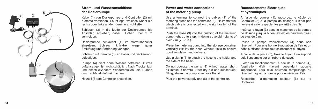
Strom- und Wasseranschlüsse der Dosierpumpe Kabel (1) von Dosierpumpe und Controller (2) mit Klemme verbinden. Es ist egal welches Kabel sie rechts oder links an der Klemme anschließen.
Schlauch (3) in die Muffe der Dosierpumpe bis Anschlag schieben, dabei Höhen über 2 m vermeiden.
Dosierpumpe senkrecht (4) im Vorratsbehälter einsetzen, Schlauch knickfrei, wegen guter Entlüftung und Förderung verlegen.
Schlauch mit Klemme (5) an Halter und Beckenrand befestigen.
Pumpe (4) nicht ohne Wasser betreiben, kurzes Luftansaugen ist nicht schädlich. Nach Trockenlauf und anschließendem Wiederbefüllen, die Pumpe durch schütteln luftfrei machen.
Netzteil (6) am Controller anstecken.
Power and water connections of the metering pump Use a terminal to connect the cables (1) of the metering pump and the controller (2). It is immaterial which cable is connected on the right or left of the terminal.
Push the hose (3) into the bushing of the metering pump right up to stop; in doing so avoid heights of over 2 m (78.7 in.).
Plase the metering pump into the storage container vertically (4); lay the hose without kinks to ensure good ventilation and delivery.
Use a clamp (5) to attach the hose to the holder and the side of the basin.
Do not operate the pump (4) without water; short air intake is harmful. After dry run and subsequent filling, shake the pump to remove the air.
Plug the power supply unit (6) to the controller.
Raccordements électriques et hydrauliques A l’aide du bornier (1), raccordez le câble du Controller (2) à la pompe de dosage. Il n’est pas nécessaire de respecter les polarités des fils.
Insérez le tuyau (3) dans le manchon de la pompe de dosage jusqu’à butée, évitez les hauteurs d’eau de plus de 2 m.
Posez la pompe verticalement (4) dans son réservoir. Pour une bonne évacuation de l’air et un débit suffisant, évitez tout coincement du tuyau.
A l’aide de la pince (5), fixez le tuyau à un support puis l’ensemble sur un rebord de cuve.
Evitez un fonctionnement à sec de la pompe (4), l’aspiration d’air n’ayant cependant aucune importance. Lors d’un nouveau remplissage du réservoir, agitez la pompe pour en évacuer l’air.
Raccordez l’alimentation secteur (6) sur le Controller.

36 37
Befestigung des Zulaufschlauches für Osmolator Zulaufschlauch an separatem Spannhalter mit Schlauchschelle, Schraube und Mutter befestigen.Klemmhalter vormontieren (1).
Auf festen Sitz achten!Ersatzteile:0102.450 Spannhalter5000.240 Schlauchschelle
Wasserrücklauf in den Vorratsbehälter vermeiden, deshalb Schlauchende immer deutlich über dem Wasserspiegel befestigen (2/3). Bei Unterschrank-Filteranlagen: Nur wenn der maximale Wasserspiegel des Vorratsbehälters niedriger als der Filterbeckenwasserstand ist, kann das Dosierwasser direkt in das Filterbecken einlaufen.
Attachment of the feed hose for the Osmolator Use a mounting clamp with hose clamp, screw and nut to fit the feed hose.Premount the clamp-type holder (1).
Ensure a tight fit !Spare parts:0102.450 mounting clamp5000.240 hose clamp
Prevent water from flowing back into storage container; for this reason, always attach the hose clearly above the water level (2/3). In case of cabinet filter plants: The metering water can flow directly into the filter tank only, if the maximum water level of the storage container is lower than the water level in the filter tank.
Fixation du tuyau d’amenée d’eau pour Osmolator Fixez le tuyau d’amenée d’eau sur le support à l’aide du collier de serrage, de la vis et de l’écrou plastique (1).
Vérifiez la bonne assise du support sur l’aquarium!Pièces détachées:0102.450 Support5000.240 Collier de serrage
Afin d’éviter un retour d’eau dans le réservoir, fixez toujours le tuyau d’amenée bien au-dessus du niveau d’eau de l’aquarium (2/3).En filtrations sous aquarium : l’amenée d’eau peut uniquement se faire directement dans la filtration si le niveau d’eau du réservoir est inférieur à celui de la filtration.
38 39
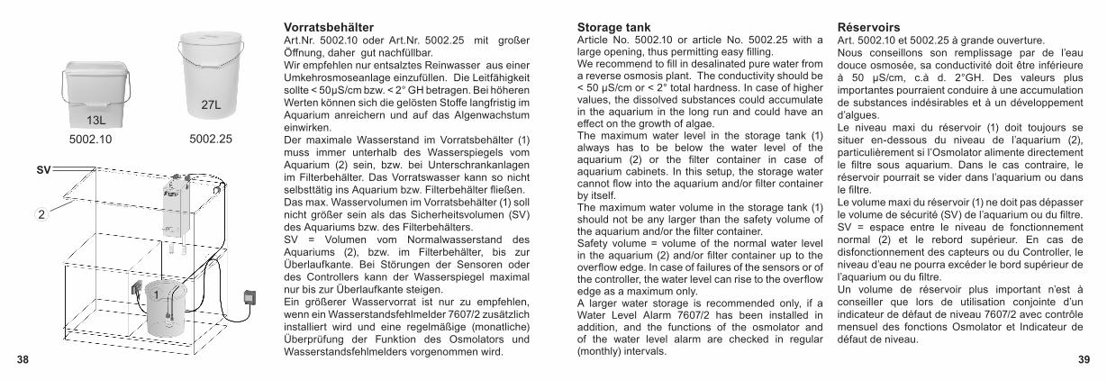
Vorratsbehälter Art.Nr. 5002.10 oder Art.Nr. 5002.25 mit großer Öffnung, daher gut nachfüllbar.Wir empfehlen nur entsalztes Reinwasser aus einer Umkehrosmoseanlage einzufüllen. Die Leitfähigkeit sollte < 50µS/cm bzw. < 2° GH betragen. Bei höheren Werten können sich die gelösten Stoffe langfristig im Aquarium anreichern und auf das Algenwachstum einwirken.Der maximale Wasserstand im Vorratsbehälter (1) muss immer unterhalb des Wasserspiegels vom Aquarium (2) sein, bzw. bei Unterschrankanlagen im Filterbehälter. Das Vorratswasser kann so nicht selbsttätig ins Aquarium bzw. Filterbehälter fließen.Das max. Wasservolumen im Vorratsbehälter (1) soll nicht größer sein als das Sicherheitsvolumen (SV) des Aquariums bzw. des Filterbehälters.SV = Volumen vom Normalwasserstand des Aquariums (2), bzw. im Filterbehälter, bis zur Überlaufkante. Bei Störungen der Sensoren oder des Controllers kann der Wasserspiegel maximal nur bis zur Überlaufkante steigen.Ein größerer Wasservorrat ist nur zu empfehlen, wenn ein Wasserstandsfehlmelder 7607/2 zusätzlich installiert wird und eine regelmäßige (monatliche) Überprüfung der Funktion des Osmolators und Wasserstandsfehlmelders vorgenommen wird.
Storage tank Article No. 5002.10 or article No. 5002.25 with a large opening, thus permitting easy filling.We recommend to fill in desalinated pure water from a reverse osmosis plant. The conductivity should be < 50 µS/cm or < 2° total hardness. In case of higher values, the dissolved substances could accumulate in the aquarium in the long run and could have an effect on the growth of algae.The maximum water level in the storage tank (1) always has to be below the water level of the aquarium (2) or the filter container in case of aquarium cabinets. In this setup, the storage water cannot flow into the aquarium and/or filter container by itself.The maximum water volume in the storage tank (1) should not be any larger than the safety volume of the aquarium and/or the filter container.Safety volume = volume of the normal water level in the aquarium (2) and/or filter container up to the overflow edge. In case of failures of the sensors or of the controller, the water level can rise to the overflow edge as a maximum only.A larger water storage is recommended only, if a Water Level Alarm 7607/2 has been installed in addition, and the functions of the osmolator and of the water level alarm are checked in regular (monthly) intervals.
Réservoirs Art. 5002.10 et 5002.25 à grande ouverture.Nous conseillons son remplissage par de l’eau douce osmosée, sa conductivité doit être inférieure à 50 µS/cm, c.à d. 2°GH. Des valeurs plus importantes pourraient conduire à une accumulation de substances indésirables et à un développement d’algues.Le niveau maxi du réservoir (1) doit toujours se situer en-dessous du niveau de l’aquarium (2), particulièrement si l’Osmolator alimente directement le filtre sous aquarium. Dans le cas contraire, le réservoir pourrait se vider dans l’aquarium ou dans le filtre.Le volume maxi du réservoir (1) ne doit pas dépasser le volume de sécurité (SV) de l’aquarium ou du filtre.SV = espace entre le niveau de fonctionnement normal (2) et le rebord supérieur. En cas de disfonctionnement des capteurs ou du Controller, le niveau d’eau ne pourra excéder le bord supérieur de l’aquarium ou du filtre.Un volume de réservoir plus important n’est à conseiller que lors de utilisation conjointe d’un indicateur de défaut de niveau 7607/2 avec contrôle mensuel des fonctions Osmolator et Indicateur de défaut de niveau.
5002.10 5002.25
27L
SV
13L
40 41
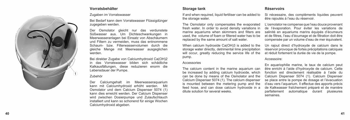
Vorratsbehälter Zugaben im Vorratswasser
Bei Bedarf kann dem Vorratswasser Flüssigdünger zugegeben werden.
Der Osmolator gleicht nur das verdunstete Süßwasser aus. Um Dichteschwankungen in Meerwasseranlagen bei Einsatz von Abschäumern und Filtern zu vermeiden, muss das entnommene Schaum- bzw. Filterwasservolumen durch die gleiche Menge mit Meerwasser ausgeglichen werden.
Bei direkter Zugabe von Calciumhydroxid Ca(OH)2 in das Vorratswasser bilden sich schädliche Kalkausfällungen, diese reduzieren enorm die Lebensdauer der Pumpe.
Zubehör
Der Calciumgehalt im Meerwasseraquarium kann mit Calciumhydroxid erhöht werden. Mit Osmolator und dem Calcium Dispenser 5074 (1) kann dies erreicht werden. Der Calcium Dispenser wird zwischen Dosierpumpe und Zulaufschlauch installiert und kann so schonend für einige Wochen Calciumhydroxid abgeben.
Storage tank If and when required, liquid fertiliser can be added to the storage water.
The Osmolator only compensates the evaporated fresh water. In order to avoid density variations in marine aquariums when skimmers and filters are used, the volume of foam or filtered water has to be replaced by the same amount of salt water.
When calcium hydroxide Ca(OH)3 is added to the storage water directly, detrimental lime precipitation will occur, greatly reducing the service life of the pump.
Accessories
The calcium content in the marine aquarium can be increased by adding calcium hydroxide, which can be done by means of the Osmolator and the Calcium Dispenser 5074 (1). The calcium dispenser is mounted between the metering pump and the feed hose, and can dose calcium hydroxide in a dilute solution for several weeks.
Réservoirs Si nécessaire, des compléments liquides peuvent être rajoutés à l’eau du réservoir.
L’osmolator ne compense que l’eau douce provenant de l’évaporation. Pour éviter les variations de salinité en aquariums marins équipés d’écumeurs et de filtres, l’eau d’écumage et de filtration doit être compensée par un volume d’eau de mer équivalent.
Un rajout direct d’hydroxyde de calcium dans le réservoir provoque de fortes précipitations calciques et réduit fortement la durée de vie de la pompe.
Accessoire:
En aquariophilie marine, le taux de calcium peut être enrichi à l’aide d’hydroxyde de calcium. Cette fonction est directement réalisable à l’aide du Calcium Dispenser 5074 (1). Calcium Dispenser se place entre la pompe de dosage et l’évacuation d’eau vers l’aquarium. Il effectue des apports précis de Kalkwasser fraîchement préparé et de manière parfaitement automatique durant plusieures semaines.

42 43
Leuchtdioden (LED) am Controller 5017 Beim Einschalten des Controllers wird ein automatischer Selbsttest aktiviert, während einer Sekunde leuchten alle LED‘s und es ertönt ein Warnton.
Rote LED „Too low“ blinkt = Dosierpumpe lief über 10 Minuten und wurde ausgeschaltet. Der Normalwasserstand wird nicht erreicht. Mögliche Ursachen: Vorratsbehälter leer, Schlauch verschmutzt oder geknickt, defekte Pumpe, Luft in der Pumpe, verschmutzter, defekter oder ausgehängter Arbeitssensor (2). Reset durch kurzes Trennen vom Netz möglich.
Gelbe LED „Pump on“ leuchtet = Angeschlossene Dosierpumpe (1) läuft. Die LED leuchtet und die Pumpe fördert mindestens 15 Sekunden lang. Damit wird zu häufiges Einschalten vermieden.
Grüne LED „Level“ leuchtet = Arbeitssensor (2) meldet Wasserkontakt. Wenn Arbeitssensor über 3 Sek. ohne Wasser ist (LED aus), läuft Dosierpumpe.
Light-emitting diodes (LEDs) on Controller 5017 When the controller is switched on, an automatic self-test is carried out causing all LEDs to light up for one second, also sounding a warning tone.
Red LED “Too low” is flashing = metering pump had been operating for more than ten minutes and has been switched off. The normal water level has not been reached. Potential cause: Storage container is empty; the hose is soiled or kinked; the pump is defective; air in the pump; soiled, defective or unhooked operating sensor (2). Reset is possible by short disconnection from the mains.
Yellow LED “Pump on” is lit = the connected metering pump (1) is operating. The LED is lit and the pump delivers for at least 15 seconds. Frequent switching is avoided in this way.
Green LED „Level“ is lit = the operating sensor (2) has contact to water. If the operating sensor is without water for more than 3 seconds (LED off), the metering pump starts operating.
Controller 5017 et diodes LED A l’enclenchement, le Controller effectue un auto-test. Durant une seconde, toutes les LEDs sont allumées avec un signal sonore.
LED rouge «Too low» clignote = la pompe de dosage a dépassé un temps de fonctionnement de 10 min. et se trouve stoppée. Le niveau d’eau normal n’a pas été atteint. Raisons possibles : réservoir vide, tuyau encrassé ou plié, pompe défectueuse, capteur de régulation (2) décroché ou défectueux. Reset par coupure de l’alimentation.
LED jaune «Pump on» allumée = pompe de dosage (1) en fonctionnement durant un temps mini de 15 sec. ce qui évite une trop grande fréquence de mises en service.
LED verte «Level» allumée = signalisation de présence d’eau sur le capteur de régulation (2). Si le capteur ne signale plus d’eau durant plus de 3 sec.(LED éteinte), la pompe de dosage est actionnée.

44 45
Leuchtdioden (LED) am Controller 5017 Rote LED„Too high“ leuchtet = Sicherheitssensor (3) ist aktiv bzw. hat Wasserkontakt. Die Dosierpumpe stoppt sofort, es ertönt ein Warnton.Rote LED „Too high“ und Rote LED „Too low“ leuchten und blinken gleichzeitig = Wasser ist in Controller gelangt und schaltet alle Funktionen aus. Gerät öffnen (siehe nächste Seiten), Platine trocknen, evtl. reinigen. Reset nur durch kurzzeitiges Trennen vom Netz möglich. Leuchten beide LED’s nach einigen Stunden wieder auf, können Restsalze und hohe Luftfeuchtigkeit die Ursache sein. Gerät muss in Fachwerkstatt zur Überprüfung.
LEDs on Controller 5017 Red LED „Too high“ is lit = The safety sensor (3) is active or has had contact with water. The metering pump is switched off immediately, and a warning signal is sounded.Red LED „Too high“ and red LED „Too low“ are lit and are flashing simultaneously = Water has penetrated into the controller and has switched off all functions. Open the device (see overleaf); dry the PCB and clean, if and when necessary. If both LEDs light up again after some hours, residual salts and high humidity may be the cause. The device has to be examined in a specialised workshop.
Controller 5017 et diodes LED LED rouge «Too high» est allumée = le capteur de sécurité (3) est actif et en contact avec l’eau. La pompe de dosage est immédiatement stoppée avec signalisation sonore.LED rouge «Too high» et «Too low» clignotent simultanément = de l’eau a pénétré la platine électronique du Controller, toutes les fonctions sont inhibées : ouvrez le Controller (voir p. suivante), séchez ou éventuellement nettoyez le circuit. Le reset de l’appareil s’effectue par une coupure de l’alimentation. Si les deux LED s’allument à nouveau après quelques heures, des sels conducteurs sur la platine ou de l’humidité résiduelle peuvent en être la raison. L’appareil doit être retourné en réparation.
Einstellung der Pumpenleistung „Dosing power“Die Dosierpumpe kann mittels internen Poti am Controller eingestellt werden (4). Einstellung „nano“: kleine Aquarien, für eine maximale Pumpenhöhe von 1,0m.Einstellung „medium“, Lieferzustand: mittelgroße Aquarien, für eine maximale Pumpenhöhe von 2,8m.Einstellung „max“: Aquarien bis 1.000L, für eine maximale Pumpenhöhe von 3,9m. Diese Einstellung ist auch erforderlich bei Verwendung der Schaltsteckdose 3150.11!
Setting the pumping power “Dosing power”The dosing pump can be set by means of the internal potentiometer in the controller (4). “nano” setting: small aquariums, for a maximum pumping height of 1.0m (39 in.).“medium” setting, delivery condition: medium-sized aquariums, for a maximum pumping height of 2.8m (110 in.).“max” setting: aquariums up to 1,000L (264 USgal.), for a maximum pumping height of 3.9m (154 in.). This setting is also required when using the switched socket outlet 3150.11!
Réglage de la puissance de dosage « Dosing power »La pompe de dosage est réglable dans sa puissance à l’aide du potentiomètre interne (4).Réglage „nano“: pour les petits aquariums, hauteur de pompage max. 1,0m.Réglage „médium“, réglage d’usine: pour des aquariums de volume moyen, hauteur de pompage max. 2,8m.Réglage „max.“: pour les aquariums jusqu’à 1000L, hauteur de pompage max. 3,9m. Ce réglage est aussi indispensable à l’utilisation de la prise commutable 3150.11!

46 47
Einstellen des Warntones Im Controller 5017 kann die Betriebsart des Warntons eingestellt werden.
Netzstecker ziehen!
Deckel entnehmen, dazu beide Schrauben auf Gehäuserückseite lösen.
Jumper (roter Stift) auf Platine verstellen.
Achtung, Leuchtdioden (LED) und Kabel nicht beschädigen!
Werkseinstellung (1) = Warnton, wenn Sicherheitssensor bei „Too high“ aktiviert.
Warnton (2) = Sicherheitssensor bei „Too high“ und nach Ablauf max. 10 Minuten Dosierzeit immer noch „Too low“, d. h. Vorratsbehälter ist leer gepumpt.
Warnton (3) = immer aus!
Hinweis: Wenn Warnton abgeschaltet wird, besteht keine akustische Kontrolle über fehlerhafte Funktionen. Bei fehlerhaftem Arbeitssensor z.B. schaltet der Sicherheitssensor ab, dies wird aber nur noch optisch gemeldet.
Adjusting the warning signal The mode of operation of the warning signal can be set in Controller 5017.
Remove the mains plug from the mains socket.
Remove the cover; for this purpose undo the two screws on the rear side of the housing.
Adjust the jumper (red pin) on the PCB.
Caution ! Do not damage the light-emitting diodes and cables !
Works setting (1) = warning signal, when the safety sensor is activated at „Too high“.
Warning signal (2) = safety sensor at „Too high“ and after an expiry of max. 10 minutes of metering time, it is still „Too low“, which means that the storage tank has been emptied.
Warning signal (3) = always off !
Note: When the warning signal has been switched off, there is no acoustic alarm of faulty functions. In case of a faulty operating sensor, for example, the safety sensor switches the system off, however this fact is only indicated optically.
Ajustage du signal sonore Le Controller 5017 permet un ajustage du signal sonore.
Déconnectez l’alimentation électrique!
Ouvrez le couvercle. Pour cela, déposez les deux vis de fermeture à l’arrière de l’appareil. Veillez à ne pas abîmer les diodes LED
Déplacer le Jumper rouge sur la platine.
Remontez l’ensemble en veillant à la bonne mise en place des différents câbles.
Réglage d’usine (1) = alarme sonore uniquement si le capteur de sécurité «Too high» est actionné.
Alarme sonore (2) = si le capteur de sécurité «Too high» est actionné et si un temps de dosage maxi de 10 min. est dépassé, LED «Too low» actionnée, réservoir vide.
Alarme sonore (3) = signal sonore inhibé
Remarque : Si le signal sonore est inhibé, il n’y a plus de signalisation acoustique des défauts. En cas de défectuosité du capteur de régulation et d’action sur le capteur de sécurité, seule subsistera la signalisation lumineuse.
Jumper
Jumper

48 49
Inbetriebnahme in Unterschrankanlagen Vorratsbehälter (1) mit Wasser auffüllen.
Arbeitssensor auf gewünschten Wasserstand stellen (2).
Sicherheitssensor auf Kapazität des Aquariums oder Filterbehälters abstimmen (3).
Sicherheitssensor in Unterschrank-Filteranlagen so positionieren, dass bei Stopp der Rückförderpumpe kein Alarm ausgelöst wird.
Die gesamten wasserführenden und elektronischen Systeme, insbesondere den Zulaufschlauch (4) wöchentlich auf richtige Befestigung am Aquarium und Dichtigkeit prüfen. Sensoren auf Funktion überprüfen!
Bei Aquarien über 1.000L empfehlen wir den Einsatz der Schaltsteckdose 3150.11 am Platz der Dosierpumpe 5000.02. Ab dieser Beckengröße verdunstet mehr Aquarienwasser, deshalb kann eine stärkere Dosierpumpe wie z.B. die Rückförderpumpe Silence 1073.020 oder 1073.040 verwendet werden.
Initial operation in aquarium cabinets Fill the storage container (1) up with water.
Set the operating sensor to the requested water level (2).
Harmonise the safety sensor to the capacity of the aquarium or the filter tank (3).
Position the safety sensor in the aquarium cabinet in such a way that no alarm is triggered by stopping the recirculation pump.
The entire water-bearing and electronic system, in particular the feed hose (4), have to be checked for correct attachment to the aquarium and for tightness once a week. Check the sensors for correct function !
For aquariums with a volume of over a 1,000 litres (264 USgal.), we recommend the use of the switched socket outlet 3150.11 (7) instead of metering pump 5000.02. As from this tank size, more aquarium water evaporates, thus a more powerful metering pump, such as the recirculation pump Silence 1073.020 or 1073.040, can be used.
Mise en service en filtrations sous aquarium Remplissez le réservoir (1).
Positionnez le capteur de régulation au niveau désiré (2).
Adaptez la position du capteur de sécurité à la capacité de l’aquarium ou du filtre sous aquarium (3).
Positionnez le capteur de sécurité de telle manière à ce qu’un arrêt de la pompe de reprise ne puisse déclencher l’alarme de débordement.
Vérifiez très régulièrement le montage et plus particulièrement la bonne fixation du tuyau d’amenée d’eau (4).
Vérifiez la fonction des capteurs!
En raison du volume d’évaporation des aquariums de plus de 1.000L, nous conseillons l’utilisation de la prise commandée 3150.11 avec pompe de reprise Silence 1073.02 / 1073.04 à la place de la pompe de dosage 5000.02.
50 51
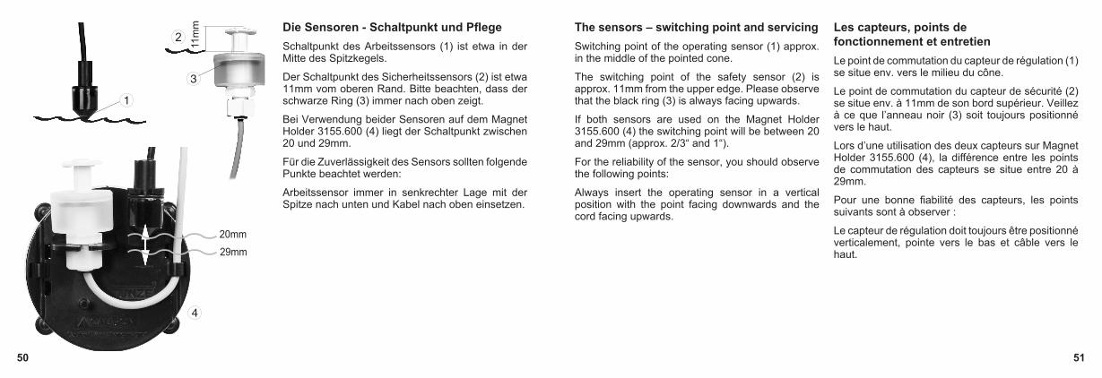
Die Sensoren - Schaltpunkt und Pflege Schaltpunkt des Arbeitssensors (1) ist etwa in der Mitte des Spitzkegels.
Der Schaltpunkt des Sicherheitssensors (2) ist etwa 11mm vom oberen Rand. Bitte beachten, dass der schwarze Ring (3) immer nach oben zeigt.
Bei Verwendung beider Sensoren auf dem Magnet Holder 3155.600 (4) liegt der Schaltpunkt zwischen 20 und 29mm.
Für die Zuverlässigkeit des Sensors sollten folgende Punkte beachtet werden:
Arbeitssensor immer in senkrechter Lage mit der Spitze nach unten und Kabel nach oben einsetzen.
The sensors – switching point and servicing Switching point of the operating sensor (1) approx. in the middle of the pointed cone.
The switching point of the safety sensor (2) is approx. 11mm from the upper edge. Please observe that the black ring (3) is always facing upwards.
If both sensors are used on the Magnet Holder 3155.600 (4) the switching point will be between 20 and 29mm (approx. 2/3“ and 1“).
For the reliability of the sensor, you should observe the following points:
Always insert the operating sensor in a vertical position with the point facing downwards and the cord facing upwards.
Les capteurs, points de fonctionnement et entretien Le point de commutation du capteur de régulation (1) se situe env. vers le milieu du cône.
Le point de commutation du capteur de sécurité (2) se situe env. à 11mm de son bord supérieur. Veillez à ce que l’anneau noir (3) soit toujours positionné vers le haut.
Lors d’une utilisation des deux capteurs sur Magnet Holder 3155.600 (4), la différence entre les points de commutation des capteurs se situe entre 20 à 29mm.
Pour une bonne fiabilité des capteurs, les points suivants sont à observer :
Le capteur de régulation doit toujours être positionné verticalement, pointe vers le bas et câble vers le haut.
11m
m
20mm29mm

52 53
Sensoren vor Schmutz und Salzkrusten schützen, deshalb regelmäßig schonend reinigen, Kratzen beschädigt den Sensor (5) .
Reinigungsintervalle bei stark besetzten Becken spätestens nach 6 Monaten durchführen. Kalkalgen oder Kalkkrusten mit Essig entfernen (5).
Luftblasen um Sensor vermeiden (6).
Sensor immer gerade nach unten, nicht schräg einbauen (7).
Regelmäßig auch die Funktion des Sicherheitssensors kontrollieren; nach Anheben des Schwimmers muss Dosierpumpe abschalten.
Protect the sensors against dirt and mineral film;; for this reason, clean them gently in regular intervals as scratching will damage the sensor (5).
In case of tanks with a lot of live stock, cleaning should be carried out every six months at the latest. Use vinegar to remove calcareous algae or lime (5).
Prevent air bubbles near the sensors (6).
Install sensors pointing straight down: never fit them at an angle (7).
Check the function of the safety sensor in regular intervals as well; after lifting the float, the metering pump has to switch off.
Protégez le capteur de régulation des saletés et des incrustations salines. Pour cela, effectuez un entretien régulier. Les rayures endommagent le capteur (5).
Dans des bacs très peuplés, effectuez un entretien tous les 6 mois. Les algues calcaires se nettoient avec du vinaigre (5).
Evitez la présence de bulles et de mouvements d’eau autour du capteur (6).
Positionnez toujours le capteur vers le bas, non de manière inclinée (7).
Vérifiez régulièrement le fonctionnement du capteur de sécurité. Son action doit stopper la pompe de dosage.

54 55
27L
5002.250ø 34 x 43,5cm
3150.110
5074
Zubehör Controlled Power Socket 3150.110In Aquarien über 1.000 Liter kann diese Schaltsteckdose (für Netzbetrieb) in Kombination mit einer stärkeren Rückförderpumpe die Dosierpumpe 5000.020 des Osmolators® ersetzen. Die Schaltsteckdose hält eine Last bis max. 1.800 W bei 230 V (900 W bei 115 V). Im Controller muss dafür die Leistung auf „max“ eingestellt werden, siehe Kapitel „Einstellung der Pumpenleistung“. Calcium Dispenser 5074Mit dem Osmolator® und dem Calcium Dispenser 5074 kann der Calciumgehalt in Meerwasseraquarien mittels Calciumhydroxid erhöht werden. Der Calcium Dispenser wird zwischen Dosierpumpe und Zulaufschlauch installiert und kann somit schonend für einige Wochen Calciumhydroxid zugeben.Vorratsbehälter 5002.250Behälter mit 27 Liter, große Deckelöffnung, handlich beim Füllen und Reinigen. Für ein offenes 600 Liter Becken: Füllung reicht ca. eine Woche.Valve 8555.200Wasserventil mit Niedervoltspannung 9-12 V DC. Ersetzt die beiliegende Dosierpumpe im Osmolator®, z.B. bei mehreren Aquarien mit Wasserleitung durch Schwerkraft. Im Controller muss dafür die Leistung auf „max“ eingestellt werden, siehe Kapitel „Einstellung der Pumpenleistung“.
Accessories Controlled Power Socket 3150.110For aquariums with more than 1,000 liters (264 USgal.), this Controlled Power Socket (for mains operation) in combination with a more powerful recirculation pump can replace the metering pump 5000.020 of the Osmolator®. The Controlled Power Socket can withstand a load up to max. 1,800 W with 230 V (900 W with 115 V). For this, the performance must be set to “max“ on the controller; see chapter “Setting the pump power”.Calcium Dispenser 5074By means of the Osmolator® and the Calcium Dispenser 5074, the calcium content in the marine aquarium can be increased by means of calcium hydroxide. The calcium dispenser is fitted between metering pump and feed hose, and thus can gently add calcium hydroxide for some weeksStorage Container 5002.250Container with a contents of 27 liters, large opening in the lid, handy for filling and cleaning. Suitable for an open 600 liters tank: fill lasts for approx. 1 week.Valve 8555.200Water valve, operating on low voltage 9 to 12 V DC. Replaces the enclosed meter pump in the Osmolator® for several aquariums with gravity line, for example. For this, the performance must be set to “max“ on the controller; see chapter “Setting the pump power”.
Accessoires Controlled Power Socket 3150.110Pour des aquariums de plus de 1.000 litres, la pompe de dosage 5000.020 peut être remplacée par cette prise commutable (fonctionnant sur le secteur) en combinaison avec une pompe de reprise plus puissante. La prise commutable supporte une charge de 1.800 W en 230 V (900 W en 115 V). Dans le Controller 5017, le potentiomètre de puissance doit être positionné sur « max »; voir chapitre « Réglage de la puissance ».Calcium Dispenser 5074En aquariophilie marine, le taux de calcium peut être enrichi à l’aide d’hydroxyde de calcium. Cette fonction est directement réalisable à l’aide du Calcium Dispenser 5074. Calcium Dispenser se place entre la pompe de dosage et l’évacuation d’eau vers l’aquarium. Il effectue des apports précis de Kalkwasser fraîchement préparé et de manière parfaitement automatique durant plusieures semaines. Réservoir 5002.250Réservoir 27 litres de grande capacité, à ouverture large et passages pour câbles et tuyau d’alimentation. Pratique à utiliser et à nettoyer, sa capacité suffit à un aquarium non-couvert de 600 litres avec un seul remplissage hebdomadaire.Valve 8555.200Electrovanne en tension de sécurité 9 - 12 V DC. Remplace la pompe de dosage de l’Osmolator®, par exemple pour plusieurs aquariums avec une alimentation d’eau par gravité. Dans le Controller 5017, le potentiomètre de puissance doit être positionné sur « max »; voir chapitre « Réglage de la puissance ».
5002.250
8555.200

56 57
Teileabbildung •Illustrations of parts •Illustration des pièces 3155.000 Teileliste List of parts Liste des pièces
1 5017.000 Osmolator® Controller Osmolator® Controller Osmolator® Controller 2 5016.100 Hakenbänder Velcro® 2x5,5cm Velcro® strips 2x5,5cm (2.1 in.) Bandes Velcro®, 2x5,5cm 3 5000.020 Metering pump Metering pump Pompe de dosage
4 5000.390 PVC-Schlauch, ø4 x 7mm x 3m PVC hose - diam. 4 x 7mm x 3m (diam. .15 x .27 x 118.1 in.) Tuyau PVC, ø4 x 7mm x 3m
5 5012.010 Netzteil Power supply unit Alimentation secteur6 3155.600 Magnet Holder für zwei Sensoren Magnet holder for two sensors Magnet Holder pour 2 capteurs7 3152.512 Magnet Holder Magnet Holder Magnet Holder8 3152.630 Sensorgehäuse Sensor housing Coquille de capteur9 6200.509 9 Elastikpuffer für Magnet Holder 9 elastic pads for Magnet Holder 9 tampons pour Magnet Holder
10 0102.450 Spannhalter Mounting clamp Support universel 11 5000.240 Schlauchschelle Hose clamp Collier de serrage 12 3155.610 Halter für Optosonde Support for optical sensor Support de capteur optique
Die Teileabbildung zeigt die mitgelieferten Einzelteile. Die Ersatzteilliste enthält auch Teile die von den Teileabbildungen abweichen können. The illustration shows the individual parts supplied. The list of spare parts may also contain parts which deviate from the illustrations. L’illustration des pièces indique les différentes pièces utilisées. La liste de pièces détachées comporte aussi des pièces pouvant différer de cette illustration.
58 59
TUNZE® Aquarientechnik GmbHSeeshaupter Straße 6882377 PenzbergGermanyTel: +49 8856 2022Fax: +49 8856 2021www.tunze.com Email: [email protected]
Hig
h Te
ch A
quar
ium
Eco
logy
Garantie Für das von TUNZE® Aquarientechnik GmbH hergestellte Gerät wird für einen Zeitraum von vierundzwanzig (24) Monaten ab dem Kaufdatum eine begrenzte Garantie gewährt, die sich auf Material- und Fabrikationsmängel erstreckt. Im Rahmen der entsprechenden Gesetze beschränken sich Ihre Rechtsmittel bei Verletzung der Gewährleistungspflicht auf die Rückgabe des von TUNZE® Aquarientechnik GmbH hergestellten Gerätes zur Reparatur oder zum Ersatz, was im Ermessen des Herstellers liegt. Im Rahmen der entsprechenden Gesetze sind dies die einzigen Rechtsmittel. Folgeschäden und sonstige Schäden sind ausdrücklich davon ausgeschlossen. Defekte Geräte müssen in der Originalverpackung zusammen mit dem Kassenzettel in einer freigemachten Sendung an den Händler oder den Hersteller gesandt werden. Unfreie Sendungen werden vom Hersteller nicht angenommen.Garantieausschluss besteht auch für Schäden durch unsachgemäße Behandlung (z.B. Wasserschäden), technische Änderungen durch den Käufer, oder durch Anschluss an nicht empfohlene Geräte.Technische Änderungen, insbesondere solche, die der Sicherheit und dem technischen Fortschritt dienen, behält sich der Hersteller vor.
Warranty The unit manufactured by TUNZE® Aquarientechnik GmbH carries a limited guarantee for a period of twenty-four (24) months after the date of purchase covering all defects in material and workmanship. Within the framework of the corresponding laws, your remedies in case of a violation of the guarantee obligation shall be limited to returning the unit manufactured by TUNZE® Aquarientechnik GmbH for repair or replacement at the discretion of the manufacturer. Within the framework of the corresponding laws, the said shall be the only remedies. Consequential damage and/or other damage shall be excluded therefrom explicitly. Defect units shall have to be shipped to the dealer or the manufacturer in the original packaging together with the sales slip in a pre-paid consignment. Unpaid consignments will not be accepted by the manufacturer.Exclusion from guarantee shall exist also in case of damage caused by inexpert handling (such as water damage), technical modification carried out by the buyer or by connection to devices which have not been recommended.Subject to technical modifications, especially those which further safety and technical progress.Customers in USA, please refer to seperate Limited Warranty for United States brochure.
Garantie Cet appareil manufacturé par TUNZE® Aquarientechnik GmbH bénéficie d’une garantie limitée à une durée légale de vingt quatre mois (24) à partir de la date d’achat et concernant les vices de fabrication et de matériaux. Dans le cadre des lois correspondantes, les voies de recours lors d’un dommage se limitent au retour de l’appareil produit par TUNZE® Aquarientechnik GmbH à son service réparation ou au remplacement de l’appareil ce qui reste de l’appréciation du fabriquant. Dans le cadre des lois correspondantes, il s’agit de l’unique voie de recours. D’autres dommages et dégâts en sont catégoriquement exclus. Les appareils défectueux doivent être expédiés dans leur emballage d’origine, accompagnés du bordereau de caisse dans un envoi affranchi à l’adresse du commerçant ou du fabricant. Les envois non affranchis ne sont pas acceptés par le fabricant.L’exclusion de garantie concerne aussi les dégâts par traitement incorrect (par exemple des dégâts causés par l’eau), les modifications techniques effectuées par l’acheteur ou le raccordement à des appareillages non recommandés par le fabricant.Le fabricant se réserve le droit d’effectuer des modifications techniques, en particulier dans le domaine de la sécurité et du progrès technique.

60 61
Störung: Gelbe LED „Pump on“ leuchtet und die Dosierpumpe läuft, es kommt aber kein Wasser. Nach ca. 10 Minuten erlischt gelbe LED und rote LED „too low“ leuchtet und die Dosierpumpe ist ausgeschaltet.
Ursache: Kein Wasser im Behälter.Abhilfe: Wasser nachfüllen.Ursache: Luft in Dosierpumpe, z.B. nach
Neubefüllung des Vorratsbehälters.Abhilfe: Pumpe unter Wasser zur Seite legen oder
umdrehen, evtl. Zulaufschlauch kurz von Pumpe lösen.
Ursache: Schlauch geknickt, verstopft.Abhilfe: Schlauchführung überprüfen.
Störung: Es wird ständig Wasser nachgefüllt, obwohl es nicht nötig ist.
Ursache: Um den Sensor herum haben sich Luftbläschen gebildet. Der Sensor nimmt somit an, dass er sich nicht im Wasser befindet.
Abhilfe: Den Sensor mit Spülmittel säubern.Ursache: Siphoneffekt des Zulaufschlauches
infolge falscher Installation.Abhilfe: Das Wasserniveau des Vorratsbehälters
darf nicht höher sein als das Ende des Zulaufschlauches, siehe Befestigung des Zulaufschlauches.
Failure: Yellow LED „Pump on“ is list and the metering pump is operating, but no water is pumped. After approx. 10 minutes the yellow LED goes off, and the red LED „Too low“ lights up, and the metering pump is switched off.
Cause: No water in tank.Remedy: Fill in water.Cause: Air in metering pump, after refilling the
storage tank, for example.Remedy: Incline or turn the pump below water;
undo feed hose briefly from the pump.Cause: Hose kinked or clogged.Remedy: Check hose.
Failure: Water is filled continuously, although this is not necessary at all.
Cause: Air bubble have formed around the sensor. The sensor thus assumes it is not located in the water.
Remedy: Use detergent to clean the sensor.Cause: Siphon effect of the feed hose due to
wrong installation.Remedy: The water level of the storage container
must not be higher than the end of the feed hose; please refer to the chapter titled “Attachment of the feed hose”.
Disfonctionnements : La LED jaune «Pump on» est allumée et la pompe fonctionne, mais aucune eau n’arrive. Après 10 min., la LED jaune s’éteint, la LED rouge «Too low» s’allume et la pompe s’arrête.
Raisons : Réservoir vide.Solutions : Remplir le réservoir.Raisons : La pompe de dosage comporte un poche
d’air suite au remplissage du réservoir.Solutions : Inclinez ou secouez la pompe. Décrochez
éventuellement le tuyau d’alimentation. Raisons : Tuyau plié ou bouché.Solutions : Vérifiez le bon passage du tuyau.
Disfonctionnements : De l’eau est constamment rajoutée malgré un niveau correct.
Raisons: Des bulles d’air se sont accumulées autour du capteur, le capteur se voit ainsi hors de l’eau.
Solutions: Nettoyez le capteur avec une solution nettoyante.
Raisons : Effet de siphon au niveau du tuyau d’alimentation en raison d’une mauvaise installation.
Solutions : Le niveau d’eau dans le réservoir ne doit pas être plus haut que la sortie d’eau du tuyau, voir Fixation du tuyau d’amenée d’eau.

62 63
Störung: Grüne LED „Level“ leuchtet nicht, obwohl Arbeitssensor Wasserkontakt hat.
Ursache: Controller 5017 ist defekt.Abhilfe: Controller erneuern oder zur Reparatur an
Fachhändler oder Hersteller einschicken.
Störung: Gelbe LED „Pump on“ leuchtet und die Dosierpumpe läuft vermindert oder überhaupt nicht. Es kommt zu wenig oder überhaupt kein Wasser.Nach ca. 10 Minuten erlischt gelbe LED und rote LED „too low“ leuchtet.
Ursache: Die Dosierpumpe läuft nur noch mit verminderter Drehzahl. Pumpe läuft nur einige Sekunden oder Minuten. Der interne Strombegrenzer schaltet die Pumpe ab.
Abhilfe: Pumpe hat evtl. Wasser im Motor und muß erneuert werden. Pumpe benötigt über 1 A Strom. Wenn die Dosierpumpe nicht genug Leistung bringt, Schaltsteckdose 3150.11 und stärkere Pumpe anstelle der Dosierpumpe anschließen (siehe Zubehör).
Abhilfe: Der Leistungspoti im Controller sollte stärker eingestellt werden, siehe Controller 5017 - Einstellung der Pumpenleistung.
Failure: Yellow LED „Pump on“ is lit and the metering pump is operating at reduced power or not at all. No water or very little water is pumped. After approx. 10 minutes the yellow LED goes off and the red LED „Too low“ lights up.
Cause: The metering pump is operating at a reduced speed only. The pump is operating for a few seconds or minutes only. The internal current limiter switches the pump off.
Remedy: Pump may have water in the motor and has to be replaced. The pump needs 1 A current. If the metering pump does not delivery enough output, connect Switched Socket Outlet 3150.11 and a more powerful pump instead of the metering pump (see accessories).
Remedy: The potentiometer in the controller should be set higher, see Controller 5017 - Setting the pumping power.
Disfonctionnements : La LED jaune «Pump on» est allumée mais la pompe de dosage fonctionne à bas régime ou pas du tout. Peu ou pas d’eau est amenée vers l’aquarium. Après 10 min., la LED jaune s’éteint et la LED rouge «Too low» s’allume.
Raisons : La pompe de dosage fonctionne uniquement à vitesse réduite durant quelques secondes ou minutes. La limitation interne du Controller limite la pompe.
Solutions : De l’eau pourrait avoir pénétré le moteur de la pompe, son remplacement complet est indispensable. La pompe nécessite un courant de plus de 1A. Si les performances de la pompe devaient être insuffisantes, veuillez utiliser une pompe plus puissante raccordée à la prise commutable 3150.11 (voir accessoires).
Solutions: le potentiomètre de puissance dans le Controller doit être augmenté, voir Controller 5017 - Réglage de la puissance de dosage „Dosing power“.
Disfonctionnements : La LED verte «Level» ne fonctionne pas malgré le contact de l’eau sur le capteur de régulation.
Raisons : Le Controller 5017 est défectueux.Solutions : Renouvelez le Controller ou faites
réparer le Controller par le détaillant ou l’usine.
Failure: Green LED „Level“ is not lit although the operating sensor has contact to water.
Cause: Controller 5017 is defective.Remedy: Replace the controller or send to the
dealer or manufacturer for repair.

64 65
Störung: Rote LEDs „Too high“ und „Too low““ leuchten zusammen und es ertönt ein akustisches Signal.
Ursache: Wasserschaden im Controller 5017.Abhilfe: Controller erneuern oder zur
Reparatur an Fachhändler oder Hersteller einschicken. Bei Wasserschäden besteht ein Garantieausschluss!
Störung: Grüne LED „Level“ leuchtet und der Arbeitssensor ist völlig trocken.
Ursache: Der Arbeitssensor ist mit Schmutz überzogen.
Abhilfe: Arbeitssensor reinigen.Ursache: Arbeitssensor, Kabel oder Controller
defekt.Abhilfe: Controller erneuern oder zur Reparatur an
Fachhändler oder Hersteller einschicken.
Failure: Red LEDs „Too high?“ and „Too low?“ are lit together and an acoustic signal is sounded.
Cause: Water damage in Controller 5017.Remedy: Replace the controller or send the unit in
to the specialist dealer or to the manufacturer for repair. Water damage will result in an exclusion of the guarantee.
Failure: Green LED „Level“ is lit and the operating sensor is completely dry.
Cause: The operating sensor is soiled.Remedy: Clean operating sensor.Cause: The operating sensor, the cable or the
controller is defective.Remedy: Replace controller or return to dealer or
manufacturer for repair.
Disfonctionnements : Les LEDs « Too high » et « Too low“ sont allumées avec alarme sonore.
Raisons : Dégât d’eau dans le Controller 5017. Solutions : Renouvelez le Controller ou faites
réparer le Controller par le détaillant ou l’usine. Un dégât d’eau est une exclusion de garantie !
Disfonctionnements : La LED verte «Level» est allumée bien que le capteur de régulation soit hors de l’eau.
Raisons : Le capteur est recouvert de saletés.Solutions : Nettoyez le capteur.Raisons : Capteur, câble ou Controller défectueux.Solutions : Renouvelez le Controller ou faites
réparer le Controller par le détaillant ou l’usine.

66 67
Störung: Rote LED „Too high“ leuchtet, erlischt und gelbe LED “Pump on“ leuchtet. Der Warnton ertönt, falls eingeschaltet.
Ursache: Der Arbeitssensor und der Sicherheitssensor sind falsch montiert.
Abhilfe: Sensoren richtig positionieren, d.h. Arbeitssensor immer unter den Sicherheitssensor.
Störung: Rote LED „Too high“ leuchtet, obwohl kein Wasser nachgefüllt worden ist. Es ertönt bei eingeschaltetem Warnton ein akustisches Signal.
Ursache: Zu viel Wasser im Aquarium, oder Unterschrankfilter, wegen Hinzufügen von Steinen oder Dekoration.
Abhilfe: Etwas Aquariumwasser entfernen.Ursache: Beim letzten Reinigen wurde der
Schwimmring des Sensors um 180° gedreht, dadurch ändert sich die Schaltrichtung.
Abhilfe: Schwimmring des Sensors durch Umdrehen in richtige Lage bringen. Siehe auch „Die Sensoren“.
Ursache: Sicherheitssensor oder Controller defekt.Abhilfe: Controller erneuern oder zur Reparatur an
Fachhändler oder Hersteller einschicken.
Failure: Red LED „Too high“ is lit, goes off, and yellow LED „Pump on“ is lit. The warning signal is sounded, when switched on.
Cause: The operating sensor and the safety sensor are not mounted correctly.
Remedy: Position sensor correctly, i.e. operating sensor always below the safety sensor.
Failure: Red LED „Too high“ is lit although no water has been filled. An acoustic signal is sounded, if the warning signal has been switched on.
Cause: Too much water in the aquarium or cabinet filter because stones or decoration has been added.
Remedy: Remove some aquarium water.Cause: The float ring of the sensor was installed
upside down during the last cleaning process. Thus, the switching direction has changed.
Remedy: Turn the float ring of the sensor into the correct position. Please also refer to the chapter titled “The sensors”.
Cause: Safety sensor or controller is defective.Remedy: Replace controller or return to dealer or
manufacturer for repair.
Disfonctionnements : La LED «Too high» s’allume - s’éteint puis la LED jaune «Pump on» s’allume avec alarme sonore.
Raisons : Les capteurs de régulation et de sécurité sont mal inversés.
Solutions : Repositionnez correctement les capteurs, capteur de régulation en-dessous du capteur de sécurité.
Disfonctionnements : La LED rouge «Too high» est allumée bien qu’aucun apport d’eau n’ai eu lieu. En cas d’utilisation, l’alarme sonore est active.
Raisons : Niveau d’eau trop important dans l’aquarium ou dans le filtre sous aquarium suite à un apport de pierres ou de décoration.
Solutions : Retirez une certaine quantité d’eau de l’aquarium.
Raisons : Lors du dernier nettoyage, le flotteur du capteur de sécurité a été inversé de 180°. Le sens de commutation est inversé.
Solutions : Repositionnez correctement le flotteur du capteur, voir aussi Capteurs, points de fonctionnement.
Raisons : Capteur de sécurité ou Controller défectueux.
Solutions : Renouvelez le Controller ou faites réparer le Controller par le détaillant ou l’usine.

68
Entsorgung(nach RL2002/96/EG)Gerät und Batterie dürfen nicht dem normalen Hausmüll beigefügt werden, sondern müssen fachgerecht entsorgt werden.Wichtig für Europa: Gerät über Ihre kommunale Entsorgungsstelle entsorgen.
Disposal(in keeping with RL2002/96/EU)The device and the battery may not be disposed of in normal domestic waste; it has to be disposed of in an expert manner.Important for Europe: Devices can be disposed of through your community’s disposal area.
Gestion des déchets(directive RL2002/96/EG)Cet appareil et sa batterie ne doivent pas être jetés dans les poubelles domestiques mais dans les conteneurs spécialement prévus pour ce type de produits.Important pour l’Europe : l’appareil doit être recyclé par votre centre de recyclage communal.