high-speed two-dimensional synchrotron x-ray … two-dimensional synchrotron x-ray radiography of...
TRANSCRIPT
ILASS Americas 28th Annual Conference on Liquid Atomization and Spray Systems, Dearborn, MI, May 2016
*Corresponding author: [email protected]
High-Speed Two-Dimensional Synchrotron X-ray Radiography of Propulsion Sprays
B. R. Halls* and J. R. Gord Aerospace Systems Directorate Air Force Research Laboratory
WPAFB, OH 45433 USA
C. D. Radke Propulsion and Power Division NASA-Johnson Space Center
Houston, TX 77058 USA
B. J. Reuter Department of Mechanical Engineering
Iowa State University Ames, IA 50011 USA
T. R. Meyer
School of Mechanical Engineering Purdue University
West Lafayette, IN 47907 USA
A. L. Kastengren X-Ray Science Division
Argonne National Laboratory Argonne, IL 60439 USA
Abstract
High-speed (120 kHz), two-dimensional x-ray imaging is demonstrated to observe dynamics and quantify the path-integrated liquid distributions in propulsion sprays. The high spatial resolution (65 µm), high temporal resolution (350 ns) measurements are made at the 7-BM beamline of the Advanced Photon Source at Argonne National Labor-atory using broadband white beam x-rays. Potassium iodide is added to the liquid at 10% by mass to increase x-ray attenuation and image contrast. A set of two imaging experiments was pursued: interrogation of a swirl coaxial spray and an impinging jet spray. The accuracy and precision of the measurements are quantified, and limitations of the technique and future strategies are discussed.

ILASS Americas 28th Annual Conference on Liquid Atomization and Spray Systems, Dearborn, MI, May 2016
*Corresponding author: [email protected]
Nomenclature EPL Equivalent Path Length I Intensity I0 Incident Intensity KI Potassium Iodide α Attenuation Coefficient Introduction
Understanding the liquid distribution in atomizing sprays is crucial to the understanding of spray breakup phenomena and has been the subject of many prior in-vestigations [1–4]. The highly dynamic nature of these sprays has prompted the use of myriad diagnostic tech-niques to interrogate the behavior of primary and sec-ondary breakup [5,6].
Measurements in the spray far field, where the liq-uid has disintegrated into a droplet field, have been performed using patternation [7,8], phase Doppler inter-ferometry [9], Mie scattering [10,11], shadowgraphy [12], schlieren [13], holography [14,15], interferometry [16,17], laser-induced fluorescence [18–21] and phos-phorescence [22], and light field imaging [23,24] A major challenge associated with optical diagnostics is multiple photon scattering events and refraction [11,25]. Due to these challenges, a new suite of dense spray diagnostics has been developed to analyze the near injector region of the spray [6]. Ballistic imaging [26–28], structured light illumination [29,30], and opti-cal connectivity [31] have proven to mitigate these ef-fects by gating of multiple scattering temporally, spa-tially, and optically, respectively.
While optical frequencies are susceptible to multi-ple scattering events and refraction, the dominant inter-action between x-rays and sprays is attenuation. Photon energies that range from 1–1000 keV are readily avail-able from commercial laboratory-scale sources and at synchrotron facilities. Therefore a complementary ap-proach to optical diagnostics is to use penetrating radia-tion such as gamma rays [32] or x-rays from tube [33–44] and synchrotron sources [45–61] to probe dense fields and inside injectors.
The current work examines the use of a broadband white beam at a bending magnet beamline to image the dynamic, spatio-temporal behavior in sprays. The im-age quality is defined, and the polychromatic nature of the beam and effects on measureable quantities are ad-dressed.
Experimental Setup
The measurements were performed at the 7-BM beamline of the Advanced Photon Source at Argonne National Laboratory [54]. In previous work at this beamline, the raw x-ray emission from the source was filtered with a double multilayer monochromator to create a monochromatic (ΔE/E = 1–4%) beam. In this study, the raw emission from the x-ray source (“white”
beam) is used, which has several effects. The x-ray flux is dramatically increased, as is the range of x-ray photon energies. The beam also lacks aberrations from the monochromator optics, providing a beam with a much more uniform profile when expanded for imaging purposes. The beam can also be expanded for imaging a larger region of the spray than when using mono-chromatic beam.
A schematic of the experiment is shown in Fig. 1. A set of mechanical slits limits the size of the beam. A series of movable filters can be used to filter out the lower-energy x-rays from the beam, reducing the inci-dent flux and altering the effective x-ray spectrum. A chopper using a 10-mm-thick spinning copper disk re-duces the duty cycle of the beam on the spray and scin-tillator to approximately 10%. Beam stops downstream of the mirror (leaded bronze, copper, and lead) are used to absorb the remaining beam that transmits through the phosphor. After the spray, a 100-µm-thick LuAG:Ce scintillator screen is used to convert the x-rays to visi-ble light. The visible emission is reflected from a mir-ror and imaged with either a 50 mm f/1.2 camera lens and captured by a high-speed CMOS camera (Photron SA-Z). The image magnification was 1.2:1 with an im-age pixel size of 21 μm. The temporal resolution was defined by the 120 kHz frame rate of the camera with a 350 ns exposure. The spatial resolution, reported as the 10–90% rise distance across a sharp opaque edge, was 65 μm. The linear range of the CMOS camera was veri-fied using white light source and neutral density filters to vary the intensity.
Figure 1. Diagram of the radiographic imaging setup in the 7BM-B beamline hutch at the APS.
The white beam contains both much higher flux and much harder x-rays than the monochromatic beam used in previous experiments at 7-BM [45–59]. This presents two challenges. First, the raw power of the beam (approximately 0.6 W/mm2 at the scintillator) can easily damage equipment, either through radiation damage to the molecular structure of materials or through excessive heating. Such damage was avoided by using the chopper noted above and limiting exposure times. The second problem is that stray high-energy x-rays scattered by the sample or beamline equipment are
occasionally absorbed in a camera pixel. Given the relatively large amount of energy in each of these pho-tons, they saturate the pixel, causing abnormally bright pixels (zingers), which degrade image quality. These absorbed x-rays can also damage electronics. A lead oxide window—transparent to visible light but opaque to x-rays—and lead shield were used to reduce these scattered x-rays, and few zingers are seen in the images as a result.
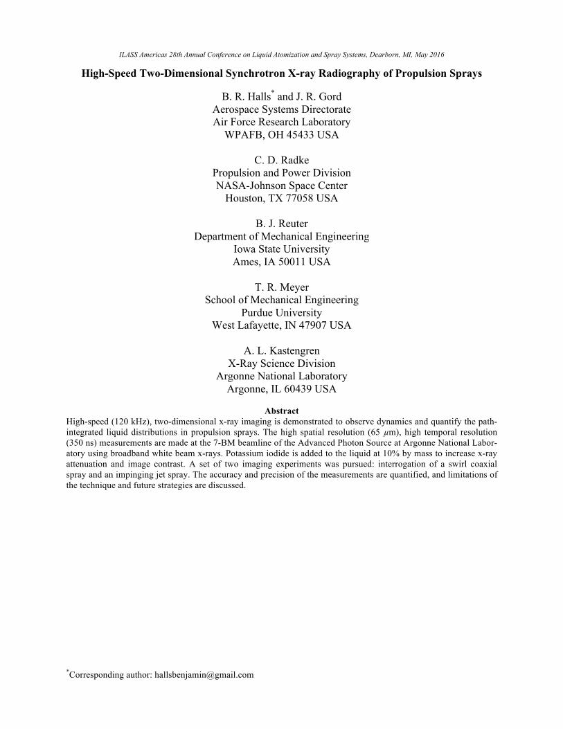
The spectrum of the white beam was altered as the beam transmitted through the spray and absorbed in the LuAG:Ce scintillator. The spray consisted of water and potassium iodide (KI) solutions. The spray preferential-ly attenuated the softer, lower energy x-rays while the higher-energy, harder x-rays were transmitted. The spectrally hardened beam illuminated the phosphor where the softer x-rays were preferentially absorbed. The intensity of the visible emission scales proportion-ally with the x-ray power absorbed by the scintillator. If the detector pixel intensity response is assumed to be linear and consistent between pixels, or if any non-linearity or non-uniformity is accounted for, the varia-ble attenuation coefficient can be determined through calibration or a theoretical model. X-ray Oriented Pro-gram 2.4 (XOP) [62] is used to model the imaging sys-tem from the incident beam through detection as a func-tion of x-ray energy. A sample of this model for x-rays attenuated by 1 mm of 50% KI solution is shown in Fig. 2, along with the effect of beam hardening by the shift in spectrum from the incident beam to the attenu-ated beam. Also shown are the effects of absorption edges from KI at 33.1 keV and from the scintillator at 63.3 keV. The model and empirical results agree to within ~5% of the attenuation through 1 mm of 10% KI solution.
Figure 2. Spectra of incident x-ray beam, detected beam, incident beam attenuated by 1 mm of 10% KI and detected beam attenuated by 1 mm of 10% KI.
The image post-processing included a flat field
normalization using an image with no spray present. The pixel intensity represents the transmission of x-rays through the spray, described as the equivalent path
length (EPL) of liquid, modified by the phosphor trans-fer function. A calibration procedure was used to map the image of transmitted light to an EPL that coupled the beam hardening in the spray, the beam-softening in the phosphor, and the visible light emission of the phosphor into a single transfer function. The transfer function is embedded in a variable attenuation coeffi-cient that is a function of the transmitted visible light and, therefore, a function of the spectral changes. The phenomena that altered the attenuation coefficient were the EPL and KI concentration; however the determina-tion of the EPL would then be iterative. In a binary sys-tem where it is assumed only the liquid is attenuating the x-rays and the effect of air attenuation is neglected, the dependence can be described as a function of the visible transmission and KI concentration. This is shown in the Beer-Lambert law in Eq. 1.
!!!= 𝑒𝑥𝑝 −𝛼 !
!!,𝐾𝐼 ×𝐸𝑃𝐿 (1)
Therefore, for each measurement where a different
concentration of KI is used, the attenuation coefficient is reduced to a function of the transmission, and the EPL can be determined without iteration. The attenua-tion coefficient was determined through calibration by imaging Kapton capillary tubes of a known diameter with various concentrations of KI ranging from 0% to 50% by mass. The attenuation coefficient was deter-mined for different levels of x-ray transmission while the liquid length and concentration were held constant. Discussion of Results
High-speed radiographic images are made in the near-field region where the liquid exits the injector and the spray is formed. The camera pixel intensity is con-verted to an EPL of liquid present along each pixel line-of-sight. The path-averaged, time-resolved liquid distri-bution is inferred from the EPL values. For optically complex but planar or axisymmetric liquid sheets, the time-resolved, two-dimensional data provide quantita-tive information about structures such as ligaments, thinned sheets, and large droplets that are known from optical images to dominate the near-field flow. Two studies were performed on an impinging jet injector and a gas-liquid swirl coaxial injector.
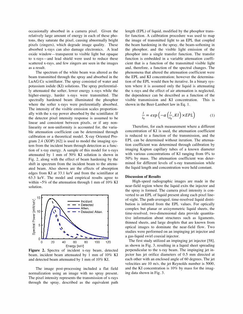
The first study utilized an impinging jet injector [58], as shown in Fig. 3, resulting in a liquid sheet spreading perpendicular to the x-ray beam. The impinging jet in-jector has jet orifice diameters of 0.5 mm directed at each other with an enclosed angle of 60 degrees. The jet velocities are 10 m/s, the jet Reynolds number is 5000, and the KI concentration is 10% by mass for the imag-ing data shown in Fig. 3.
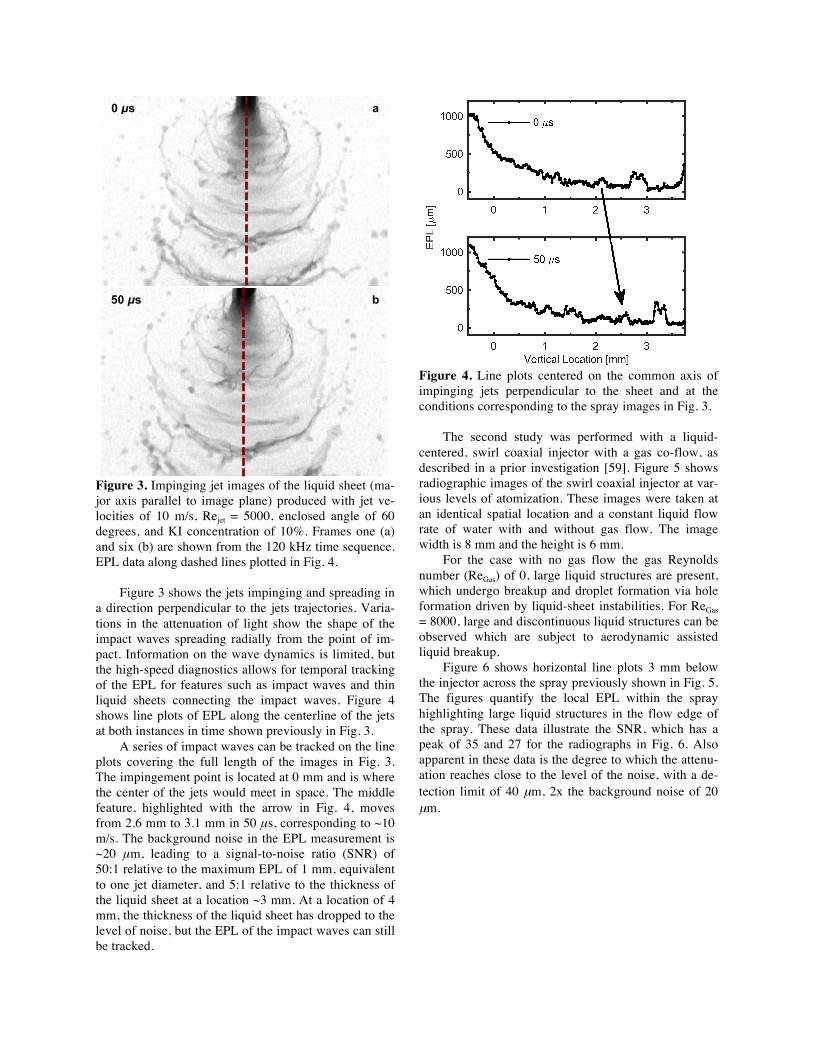
Figure 3. Impinging jet images of the liquid sheet (ma-jor axis parallel to image plane) produced with jet ve-locities of 10 m/s, Rejet = 5000, enclosed angle of 60 degrees, and KI concentration of 10%. Frames one (a) and six (b) are shown from the 120 kHz time sequence. EPL data along dashed lines plotted in Fig. 4.
Figure 3 shows the jets impinging and spreading in a direction perpendicular to the jets trajectories. Varia-tions in the attenuation of light show the shape of the impact waves spreading radially from the point of im-pact. Information on the wave dynamics is limited, but the high-speed diagnostics allows for temporal tracking of the EPL for features such as impact waves and thin liquid sheets connecting the impact waves. Figure 4 shows line plots of EPL along the centerline of the jets at both instances in time shown previously in Fig. 3.
A series of impact waves can be tracked on the line plots covering the full length of the images in Fig. 3. The impingement point is located at 0 mm and is where the center of the jets would meet in space. The middle feature, highlighted with the arrow in Fig. 4, moves from 2.6 mm to 3.1 mm in 50 μs, corresponding to ~10 m/s. The background noise in the EPL measurement is ~20 μm, leading to a signal-to-noise ratio (SNR) of 50:1 relative to the maximum EPL of 1 mm, equivalent to one jet diameter, and 5:1 relative to the thickness of the liquid sheet at a location ~3 mm. At a location of 4 mm, the thickness of the liquid sheet has dropped to the level of noise, but the EPL of the impact waves can still be tracked.
Figure 4. Line plots centered on the common axis of impinging jets perpendicular to the sheet and at the conditions corresponding to the spray images in Fig. 3.
The second study was performed with a liquid-
centered, swirl coaxial injector with a gas co-flow, as described in a prior investigation [59]. Figure 5 shows radiographic images of the swirl coaxial injector at var-ious levels of atomization. These images were taken at an identical spatial location and a constant liquid flow rate of water with and without gas flow. The image width is 8 mm and the height is 6 mm.
For the case with no gas flow the gas Reynolds number (ReGas) of 0, large liquid structures are present, which undergo breakup and droplet formation via hole formation driven by liquid-sheet instabilities. For ReGas = 8000, large and discontinuous liquid structures can be observed which are subject to aerodynamic assisted liquid breakup.
Figure 6 shows horizontal line plots 3 mm below the injector across the spray previously shown in Fig. 5. The figures quantify the local EPL within the spray highlighting large liquid structures in the flow edge of the spray. These data illustrate the SNR, which has a peak of 35 and 27 for the radiographs in Fig. 6. Also apparent in these data is the degree to which the attenu-ation reaches close to the level of the noise, with a de-tection limit of 40 µm, 2x the background noise of 20 µm.
0 µs a
50 µs b

Figure 5. Representative images collected for two lev-els of atomization in a swirl coaxial injector for a fixed liquid flow rate a) ReGas = 0 b) ReGas = 8000. EPL data along dashed lines plotted in Fig. 6.
Figure 6. Line plots centered on the common axis of swirl coaxial injector and at the conditions correspond-ing to the spray images in Fig. 5.
Conclusion High-speed, radiographic measurements were
made in an impinging jet spray and a swirl injector us-ing a new white beam synchrotron source. The change in attenuation coefficient due to x-ray beam hardening through the spray was accounted for and the uncertainty and sensitivity were addressed. Two-dimensional, spa-tially resolved (65 µm) and time-resolved (350 ns) liq-uid equivalent path length data at 120 kHz was demon-strated. Future strategies include simultaneous radiog-raphy and phase contrast imaging for edge enhance-ment of fine structures within the spray, along with use of a long distance microscope to observe dynamic drop-let behavior.
Acknowledgments Benjamin Halls is funded under a National Research Council Post-doctoral Research Associateship award at the Air Force Research Laboratory, Aerospace Systems Directorate, Wright-Patterson AFB. The measurements were performed at the 7-BM beamline of the Advanced Photon Source, Argonne National Laboratory, support-ed by the U.S. Department of Energy under Contract No. DE-AC02-06CH11357. This manuscript has been cleared for public release by the Air Force Research Laboratory (No. 88ABW-2016-1101). References 1. Lefebvre, A.W., Atomization and Sprays, Taylor
and Francis, 1989. 2. Yang, V., Anderson, W., Liquid Rocket Engine
Combustion Instability, AIAA Inc., 1995. 3. Yang, V., Habiballah, M., Hulka, J., Popp, M.,
Liquid Rocket Thrust Chambers: Aspects of Model-ing, Analysis, and Design, AIAA Inc., 2004.
4. Ashgriz, N., Handbook of Atomization and Sprays: Theory and Applications, Springer, 2011.
5. Meyer, T. R., Brear, M., Jin, S. H., Gord, J. R., Formation and Diagnostics of Sprays in Combus-tion, Handbook of Combustion, Wiley, 2010, p. 291–322.
6. Linne, M.A., Progress in Energy and Combustion Science, 39(5): 403–440 (2013).
7. Rupe, J.H., “The liquid-phase mixing of a pair of impinging streams,” Jet Propulsion Laboratory Progress Report 20-195, 1953.
8. Ashgriz, N., Brocklehurst, W., and Talley, D., Journal of Propulsion and Power 17(3): 736–749 (2001).
9. Bachalo, W.D., Applied Optics 19(3): 363–370 (1980).
10. Dobbins, R.A., Crocco, L., and Glassman, I., AIAA Journal 1(8): 1882–1886 (1963).
11. Talley, D.G., Thamban, A.T.S., McDonell, V.G., and Samuelsen, G.S., Laser Sheet Visualization of spray structure, Recent advances in spray combus-
Flow Directio
n
a

tion: spray atomization and drop burning phenom-ena, AIAA Inc., 1995, p. 185–210.
12. Wellander, R., Berrocal, E., Kristensson, E., Rich-ter, M., and Aldén, M., Measurement Science and Technology, 22(12): 125303 (2011).
13. Settles, G., Schlieren and shadowgraph techniques. Berlin: Springer; 2001.
14. Santangelo, P.J., Sojka, P.E., Applied Optics 33(19): 4132–4136 (1994).
15. Guildenbecher, D.R., Reu, P.L., Stuaffacher, H.L. and Grasser, T. Optics Letters, 38(20): 4015–4018 (2013).
16. Fukui, N., Sato, T., Japanese Society of Mechani-cal Engineers 15(83): 609–619 (1972).
17. Choo, Y.J., Kang, B.S., Experiments in Fluids 31: 622–627 (2001).
18. Le Gal, P., Farrugia, N., and Greenhalgh, D.A., Optics and Laser Technology 31(75): 75–83 (1999).
19. McDonell, V., Phi, V., Samuelsen, S., Nejad, A., Shahnam, M.,Guernsey, C., and Carlson, R., Thir-ty-Fifth AIAA/ASME/SAE/ASEE Joint Propulsion Conference and Exhibit, Los Angeles, CA, USA June,1999.
20. Jung, K., Koh, H., Yoon, Y., Measurement Science and Technology 14(8): 1387–1395 (2003).
21. Yuan, T., and Huang, B., Atomization and Spray 22(5): 391–408 (2012).
22. Kiel, B.V., and Gord, J.R., Schmidt, J.B., Miller, J.D., and Meyer, T.R., ICLASS Eleventh Triennial International Annual Conference on Liquid Atomi-zation and Spray Systems, Vail, CO, USA, July 2009.
23. Scharfman, B.E., Hart, D.P. and Techet, A.H., Tenth International Symposium on Particle Image Velocimetry, Delft, The Netherlands, July, 2013.
24. Chen, H., Lillo, P.M. and Sick, V., Journal of En-gine Research, 1468087415608741(2015).
25. Sick, V., Stojkovic, B., Applied Optics 40(15): 2435–2442 (2001).
26. Linne, M.A., Paciaroni, M., Gord, J.R., Meyer, T.R., Applied Optics 44(31): 6627–6634 (2005).
27. Schmidt, J.B., Schaefer, Z.D., Meyer, T.R., Roy, S., Danczyk, S.A., and J. R. Gord, Applied Optics 48: 137–144 (2009).
28. Purwar, H., Idlahcen, S., Roze, C., Sedarsky, D., and Blaisot, J.-B., Optics Express 22(13): 15778–15790 (2014).
29. Berrocal, E., Kristensson, E., Richter, M., Linne, M., Aldén, M., Optics Express 16(22): 17870–17881 (2008).
30. Kristensson, E., Berrocal, E., Alden, M., Optics Express 20: 14437–14450 (2012).
31. Charalampous, G., Hardalupas, Y., Taylor, A., AIAA Journal 47(11): 2605–2615 (2009).
32. Ruff, G.A., Faeth, G.M., Recent advances in spray
combustion: spray atomization and drop burning phenomena, AIAA Inc., 1995, p. 185–210.
33. Char, J.M., Kuo, K.K., Hsieh, K.C., Journal Pro-pulsion 6(5): 544–551 (1990).
34. Woodward, R.D, Pal, S., Santoro, R.J., Kuo, K.K., Recent advances in spray combustion: spray atom-ization and drop burning phenomena, AIAA Inc., 1995, p. 185–210.
35. Meyer, T.R., Schmidt, J.B., Nelson, S.M., Drake, J.B., Janvrin D.M. Heindel, T.J., ILASS Americas 21st Annual Conference on Liquid Atomization and Spray Systems, Orlando, FL, May 2008.
36. Balewski, B., Heine, B., Tropea, C., Atomization and Sprays 20(1): 57–70 (2010).
37. Lim, J., Sivathanu, Y., Wolverton, M., ILASS Americas 25th Annual Conference on Liquid Atom-ization and Spray Systems, Pittsburgh, PA, May 2013.
38. Coletti, F., Benson, M.J., Sagues, A.L., Miller, B.H., Fahrig, R., Eaton, J.K., Journal of Engineer-ing for Gas Turbines and Power 136(5): 1–8 (2014).
39. Halls, B.R., Heindel, Meyer, T.R., Kastengren, A.L., International Journal of Multiphase Flows 59: 113–120 (2014).
40. Halls, B.R., Heindel, T.J., Meyer, T.R., ILASS Americas 26th Annual Conference on Liquid Atom-ization and Spray Systems, Portland, OR 2014.
41. Marchitto, L., Hampai, D., Dabagov, S.B., Allocca, L., Alfuso, S., Polese, C., Liedl, A., International Journal of Multiphase Flows 70: 15–21 (2015);
42. Birk, A., and McQuaid, M., “Liquid core structure of evaporating sprays at high pressures – Flash X-ray Studies,” Army Research Laboratory Technical Report 901, 2003.
43. Robert, E., Dozias, S., Vildarosa, R., Cachoncinlle, C., Pouvesle, J.M., ILASS Europe 23rd Annual Conference on Liquid Atomization and Spray Sys-tems, Brno, Czech Republic 2010.
44. Halls, B.R., Roy, S., Gord, J.R., Kastengren, A.L., and Meyer, T.R., International Journal of Multi-phase Flows, Submitted, 2016.
45. Kastengren, A.L., and Powell, C.F., Experiments in Fluids, 55(3): 1–15 (2014).
46. Powell, C.F., Yue,Y., Poola, R., and Wang, J., Journal of Synchrotron Radiation 7(6): 356–360 (2000).
47. MacPhee, A.G., Tate, M.W., Powell, C.F., Yue, Y., Renzi, M.J., Ercan, A., Narayanan, S., Fontes, E., Walther, J., Schaller, J., Gruner, S.M., and Wang, J., Science 295(5558): 1261–1263 (2002).
48. Tanner, F.X., Feigl, K., Ciatti, S.A., Powell, C.F., Cheong, S.-K., Liu, J., and Wang, J., Atomization and Sprays 16: 579–598 (2006).
49. Cai, W., Powell, C.F., Yue, Y., Narayanan, S., Wang, J., Tate, M.W., Renzi, M.J., Ercan, A., Fon-tes, E., and Gruner, S.M., Applied Physics Letters 83(8): 1671–1673 (2003).
50. Qun, S., Lee, W-K., Fezzaa K., Chu, Y.S., De Car-lo, F., Jemian, P., Ilavsky, J., Erdman, M., and Long, G., Nuclear Instruments and Methods in Physics Research Section A 582(1): 77–79 (2007).
51. Kastengren, A.L., Powell, C.F., Wang, Y.J., Im, K.-S., and Wang, J., Atomization and Sprays 19(11): 1031–1044 (2009).
52. Kastengren, A.L., Powell, C.F., Dufresne, E.M., and Walko, D.A., Journal of Synchrotron Radia-tion 18(5): 811–815 (2011).
53. Schumaker, S.A., Kastengren, A.L., Lightfoot, M.D.A., Danczyk, S.A., and Powell, C.F., ICLASS Twelfth Triennial International Annual Conference on Liquid Atomization and Spray Systems, Heidel-berg, Germany September 2012.
54. Kastengren, A.L., Powell, C.F., Arms, D.A., Du-fresne, E.M., Gibson H., and Wang J., Journal of Synchrotron Radiation 19(4): 654–657 (2012).
55. Kastengren, A.L., Tilocco, F.Z., Powell, C.F., Manin, J., Pickett, L.M., Payri, R., Bazyn, T., At-omization and Sprays 22(12): 1011–1052 (2012).
56. Duke, D.J., Kastengren, A.L., Tilocco, F.Z., Swantek, A.B. and Powell, C.F., Atomization and Sprays, 23(9): 841–860 (2013).
57. Eberhart, C.J., Lineberry, D.M., Frederick Jr., R.A., and Kastengren, A.L., Journal of Propulsion and Power 30: 1070 (2014).
58. Halls, B.R., Meyer, T.R., Kastengren, A.L., Optics Express 23(2): 1730–1739 (2015).
59. Radke, C.D., McManamen, J.P., Kastengren, A.L., Halls, B.R., Meyer, T.R., Optics Letters 40(9): 2029–2032 (2015).
60. Lin, K.C., Ryan, M., Carter, C., Sandy, A., Nara-yanan, S., Ilavsky, J., and Wang, J. ILASS Ameri-cas 21st Annual Conference on Liquid Atomization and Spray Systems, Orlando, FL, May 2008.
61. Lin, K-C., Rajnicek, C., McCall, J., Carter, C., Fezzaa, K., Nuclear Instruments and Methods in Physics Research Section A 649(1): 194–496 (2011).
62. Sanchez del Rio, M., and Dejus, R.J., SPIE Proceedings 8141: 814115 (2011).
