high speed trajectory control using an experimental...
TRANSCRIPT

High speed trajectory control using an experimental maneuverability modelfor an insect-scale legged robot
Benjamin Goldberg, Neel Doshi, and Robert J. Wood
Abstract— This paper presents an off-board trajectory con-troller for a range of stride frequencies (2-45 Hz) that enableszero-radius turns and holonomic control on one of the smallestand fastest legged robots, the Harvard Ambulatory MicroRobot(HAMR). An experimental model is used as the basis for controlto capture the highly nonlinear response of the robot to inputsignals. Closed-loop trajectories are performed with an RMSposition error at or below 0.3 body lengths (BL) using gaits atspeeds up to 6.5 BL/s (29.4 cm/s) for straight-line and sinusoidaltrajectories.
I. INTRODUCTION
Legged insects demonstrate a remarkable ability to ma-neuver through their environment during rapid running. Forexample, cockroaches can maneuver over mesh surfaces andalong walls at forward speeds exceeding 50 cm s−1 and withturning rates of two revolutions per second using distributedsensory and mechanical feedback systems ([1], [2]). In ad-dition to low-level mechanical feedback from their musculo-skeletal structures, insects use simple feedforward controllersto change muscle activation patterns and alter gait [3].Furthermore, reduced-order dynamical models (templates)such as the Lateral Leg Spring (LLS) and Sliding Spring Leg(SSL) models have explored feedforward control strategiesfor horizontal plane stabilization ([4], [5]).
Inspired by these capabilities, roboticists have developeda number of legged robots (e.g, RHex, MIT Cheetah, RiSE,and OctoRoACH) to accomplish tasks such as running overrough terrain [6], obstacle traversal [7], climbing verticalsurfaces [8], and rapid turning and trajectory control [9],[10]. Furthermore, similar tasks have been achieved withsmall scale legged robots including RoACH, DASH, andHAMR ([11], [12], [13]).
Robots such as RHex and OctoRoACH successfully im-plement leg phase and differential drive for trajectory control.In this paper, we extend phase-based control to both headingand lateral velocity. The platform used in this paper formaneuverability and control experiments is the HarvardAmbulatory MicroRobot (HAMR - Fig. 1a), a centimeter-scale, quadrupedal microrobot. Despite its small form factor(4.51 cm long and 1.43 g), HAMR has eight independentlyactuated degrees of freedom (DOFs) and can run at speedsup to 10.1BL s−1 [13]. HAMR has two DOFs per leg – a“swing” that moves in the fore-aft direction, and a “lift” themoves both vertically and laterally (described further in Sec.
The authors are with the John A. Paulson School of Engineer-ing and Applied Sciences, Harvard University, Cambridge, MA 02138,USA, and the Wyss Institute for Biologically Inspired Engineer-ing, Harvard University, Boston, MA, 02115, USA (email: bgold-berg,ndoshi,[email protected])
(a) (b)
PiezoelectricActuators
Spherical �ve-bartransmissions
Legs
TrackingMarkers
Fig. 1. (a) HAMR-VI, showing the flexure-based transmissions andquadrupedal morphology. (b) Example sinusoidal trajectory that HAMRfollows using the off-board, model-based controller.
II). This work leverages all eight DOFs and high bandwidthactuators in HAMR to develop strategies for high speed,controlled running.
In this paper, we show that leg phasing is able to controlboth heading and lateral position and these maneuvers canbe performed across varying stride frequencies and gaits.In Section II and III, we give an overview of HAMRand the maneuverability commands, and in Section IV, weperform open-loop maneuverability experiments. In someregimes, highly nonlinear effects of body dynamics andfoot-ground interaction lead to coupling between angularand lateral velocities. Since an analytical model would beprohibitively difficult to develop due to complex system dy-namics, experimental data is used to inform controller designfor these regimes. Section V describes control experimentswith two different gaits at stride frequencies of 2Hz and45Hz. Trajectory following performance is improved withthe addition of the experimental maneuverability model thatresults in an RMS-position error of only 0.07 body lengths(BL). Finally, the controller is evaluated at these low andhigh stride frequencies by following sinusoidal trajectoriesand completing an obstacle course.
II. ROBOT OVERVIEW
Previous versions of HAMR have focused on addressingdesign and manufacturing limitations to create millimeter-scale mechanisms [14]. This has enabled demonstrations ofhigh speed running and turning [13], climbing [15], andfully autonomous operation with onboard sensing [16]. Inthese demonstrations, a simple maneuverability scheme wasused to control heading and lateral velocity at speeds up to0.15BL s−1 ([16], [17]). Recent redesigns to HAMR’s legtransmissions have increased the leg force output leading toa 114% increase in its payload capacity, and in turn leadingto larger step displacements [18]. Additionally, mechanicalcoupling between contralateral swing DOFs that previouslylimited gait choice and control options has been removed

FrontTopView
Right-sideView
LFL
SFL
SFR
LFR
LRL
SRL
SRR
LRR
Forward Pronk
Front
Left Turn Pronk
(a)
Front-leftleg (FL)
Front
Right Turn Pronk
(c)
y
x
PiezoelectricActuators
Spherical�ve-bar
Legs
(b)
PiezoelectricActuators
MechanicalGround
Swing inputLift input
Leg Output “lift”“swing”
Fig. 2. (a) A perspective view of a single leg transmission and a renderingof the complete robot in the inset. (b) A top view of the robot that showsthe the poling of the piezoelectric actuators (dark grey vs. light grey),with a 180◦ offset between the front and rear actuators. Arrows at theleg and actuator tips indicate motions for a common input signal before theaddition of baseline phase offsets to achieve a ‘pronk’ gait. (c) Orthogonaltop and side views showing the projection of the leg trajectories for turns.For example, during a left turn, the intra-leg phasing for the left legs arereversed by commanding a positive phase offset to the left swing actuators.
and any desired leg phasing can be achieved. These twoimprovements have led to greater control authority. Thefollowing sections give a detailed description of a newmaneuverability strategy that uses actuator phasing to controlboth angular and lateral velocity of HAMR.
A. Actuator signal description
There are eight total DOFs in HAMR with two DOFs perleg. Each leg has a ‘swing’ and a ‘lift’ DOF (Fig. 2a andFig. 3c) that are connected to a single leg output througha flexure-based, spherical five-bar transmission. Each DOFis independently actuated by piezoelectric bimorph actuatorswith a sinusoidal voltage with three main input parametersas described by the following equation:
Vi(t) =Vb2[1 + sin(2πfdt+ φi)] (1)
Here, Vi(t) is the sinusoidal voltage signal to the ith actuatoras a function of time, t. The three important parameters are:Vb, the maximum drive voltage, fd the stride frequency, andφi, the actuator phase.
For actuator phasing, there are two subsets of leg phasevariations: inter-leg (φg) and intra-leg (φp) phasing. Theoverall actuator phase is the sum of these two phases (φi =φg + φp). While both phases directly affect gait, there aredistinct differences between the two. Inter-leg phasing is aglobal phase variable controlling footfall timings between
each of the individual legs. Intra-leg phasing is a local phasevariable between the ‘lift’ and ‘swing’ DOFs that controlsthe direction and duration of leg footfalls (i.e., swing-stancephase). Intra-leg phase for HAMR is determined by the sumof the last four columns in Table I, choosing left or right turn(φp = φb + φl||r + φh). The inter-leg and intra-leg phasingis explained in more detail in Section II-B,C, and D.
TABLE IACTUATOR PHASING FOR GAITS AND MANEUVERABILITY
i DOF*Gait
Offsetφg
BaselineOffsetφb
LeftTurnφl
RightTurnφr
LateralManeuver
φh1 LFL FLg
0◦ 0 0 -LP2 SFL 90◦ +OP 0 03 LFR FRg
180◦ 0 0 +LP4 SFR 270◦ 0 +OP 05 LRR RRg
0◦ 0 0 +LP6 SRR 270◦ 0 -OP 07 LRL RLg
180◦ 0 0 -LP8 SRL 90◦ -OP 0 0
*e.g., “LFL”: Lift-front-left, “SRR”: Swing-rear-right“OP”: Orientation Phase, “LP”: Lateral Phase
The phase for each DOF is determined by summing all columns of thetable (choosing either left or right turn). For heading control, the limits are0◦ ≤OP< 180◦ and for lateral maneuvers, the limits are −60◦ ≤LP≤ 60◦
for negative or positive lateral velocities, respectively.
Based on prior successful maneuverability experiments in[13], we decided to focus on actuator phasing to controlthe robot heading and lateral velocity. Phase is chosen for anumber of reasons. First, the basis for standard quadrupedalgaits is leg phasing and therefore phase control is alreadyavailable and can be used to fine-tune gaits. Furthermore,due to the high voltage requirements of HAMR, phasecontrol is easier to implement than voltage control on fu-ture autonomous versions of HAMR. Frequency is anotherviable option to control heading, however this strategy wouldpreclude turning in place.
B. Baseline offset
In order to command standard quadrupedal gaits, me-chanical and electrical offsets due to actuator phasing andtransmission design need to be taken into consideration. Forexample, contralateral lift DOFs move in opposite directions(up vs. down) when given the same input signal. Theseconsiderations are shown with the arrows in Fig. 2b and theymake up the baseline phase offsets in Table I.
C. Inter-leg phasing (Gait Offset)
Actuator phasing is the primary method for achievingarbitrary gaits in HAMR. This inter-leg phasing controls thetime of footfall for each of the legs with respect to thefront-left leg. When φg = 0, all leg footfalls occur at thesame time, commanding the “pronk” gait. A schematic ofthe leg trajectories for the pronk are shown in Fig. 2c. Inputsignals for the pronk gait are shown in Fig. 3a with thecorresponding expected footfall pattern in (b), and experi-mental leg trajectories in air tracked in (c). In this paper, twogaits are explored for trajectory control: the trot and jump

0 0.5 1 1.5 20
V
Inpu
t Vol
tage
(V)
φ SFL
VSFL
VLFL
(a)
(b)
FL
RL
RR
FR
Cycles0 0.5 1 1.5 2
(c)
LiftSwing
FL
RL
RR
FR
Trot
Cycles
Jump
0 10.5 0 10.5
(d)Pronk
b
7mmdirectionof motion
Fig. 3. (a) Example drive signals for the front left leg. The swing DOF inputsignal (VSFL) lags the lift DOF by 90◦ for nominal circular foot trajectories.For the trajectory control tests in this paper, the bias (Vb) voltage is 150Vand the input signal is centered around 75V. (b) Footfall patterns for the“pronk” gait. (c) Foot trajectories from a side-view perspective of the robotsuspended on blocks commanding a pronk gait. (d) Footfall patterns of thetrot and jump gaits.
(footfall patterns shown in Fig. 3d). These gaits are chosenfor the ability to achieve high speeds over a range of stridefrequencies, however the same maneuverability scheme hasbeen tested and applies to all standard quadrupedal gaits forHAMR (e.g., pronk, canter, bound, etc.). It is important tomention that gaits are commanded in the open-loop sense andthe timing of actual ground contact may differ from timingprescribed by the input commands.
D. Intra-leg phasing
Swing and stance phase is used to control the local, intra-leg phasing, φp. While changing the intra-leg phasing alsoaffects the observed gait, it does so through variations in theshape of the leg trajectory whereas inter-leg phasing does notmodify leg trajectory to alter gait. The last four columns ofTable I control the intra-leg phasing with φp = φb+φl||r+φh.The maneuverability scheme for turns and lateral maneuversare described in the following section.
III. MANEUVERABILITY SCHEME
The first step to develop a trajectory controller is todesign and characterize the performance of an open-loopmaneuverability scheme.
A. Heading phase command
The basis for heading control for HAMR is differentialdrive (i.e., “tank steering”) as is common in wheeled robotsand some other legged robots (e.g., DASH [12] and Oc-toRoACH [9]). Leg phase (intra-leg) is used to slow downor reverse the direction of the leg trajectory on the sameside of the robot as the desired turn. For a left turn, theintra-leg phasing for the left leg trajectories are reversedby commanding a positive phase offset to the left swingactuators. The opposite is performed for a right turn. Thesechanges in angular velocity are commanded with the phasingmodifications shown in Table I (columns five and six). Theorientation phase is only added to either the left or rightside actuators depending on the desired turn direction and islimited to: 0◦ ≤OP< 180◦.
xPC Target Host PC
HAMR-VI
Overhead Camera High Voltage Ampli�ers
Tether
Fig. 4. The experimental setup with the overhead camera. Three whitemarkers are affixed to HAMR for high contrast with the robot chassis andwalking surface. The host PC runs the controller and sends control updatesto the xPC target that generates waveforms for the actuators that are sentto HAMR through high voltage amplifiers.
B. Lateral phase command
Unique to HAMR and other legged systems (e.g., fiddlercrabs [19]), the legs can also move in the lateral direction forsideways locomotion. For HAMR, this motion is introducedby a subset of intra-leg phasing shown in column seven ofTable I. This input has the effect of swapping the role of theswing and lateral DOFs (i.e. the robot is stepping sideways).The bounds on the lateral phase are limited to −60◦ ≤LP≤60◦ to kinematically achieve the maximum lateral velocity.
IV. FEEDFORWARD MANEUVERABILITY EXPERIMENTS
The maneuverability characteristics for HAMR are exper-imentally validated by implementing the actuator phasingstrategy of Table I. The orientation and lateral phasing isvaried from −180◦ to 180◦ and −60◦ to 60◦ with a gridspacing of 60◦ and 30◦, respectively. Seven different gaitconditions are tested over this input range – six stride fre-quencies for the trot gait and one high speed stride frequencyfor the jump gait. A total of 245 trials are recorded andtracked. The experimental setup to conduct these trials andthe results from the feedforward experiments are describedin the following sections.
A. Experimental setup
The experimental setup consists of two computers in ahost/target configuration. The target machine runs MatlabxPC at 5 kHz and receives high level commands (e.g.,changes in input actuator phase) from the host machinerunning Matlab Simulink (Mathworks, r2013b). The low-level drive signal generation is done on the target machineand signals are sent to high-voltage amplifiers (Apex, PA340)through a digital to analog converter installed in the xPCtarget (United Electronic Industries, PD2-AO-32/16). Am-plified voltages are sent through a 10-wire tether (commonpower and ground plus eight input signals) of 48 AWG wire(MWS wire, 10/48 Unserved Litz). A simple test running
2Hz
5Hz
8Hz
15Hz
20Hz
45Hz
Fore/aft Velocity(cm/stride)
Angular Velocity(degrees/stride)
Orientation Command (-180:180 degrees phase)
Late
ral C
omm
and
(-60:
60 d
egre
es p
hase
)
45HzJump
Normalized Velocity
-0.5
0
0.5
-0.5
0
0.5
-12
0
12
-500
50
-500
50
-500
50
-500
50
-500
50
-500
50
-150 -100 -50 0 50 100 150-50
050
-150 -100 -50 0 50 100 150-50
050
-150 -100 -50 0 50 100 150
-150 -100 -50 0 50 100 150-50
050
-150 -100 -50 0 50 100 150-50
050
-150 -100 -50 0 50 100 150
-150 -100 -50 0 50 100 150-50
050
-150 -100 -50 0 50 100 150-50
050
-150 -100 -50 0 50 100 150
-150 -100 -50 0 50 100 150-50
050
-150 -100 -50 0 50 100 150-50
050
-150 -100 -50 0 50 100 150
-150 -100 -50 0 50 100 150-50
050
-150 -100 -50 0 50 100 150-50
050
-150 -100 -50 0 50 100 150
-150 -100 -50 0 50 100 150-50
050
-150 -100 -50 0 50 100 150-50
050
-150 -100 -50 0 50 100 150
-150 -100 -50 0 50 100 150-50
050
-150 -100 -50 0 50 100 150-50
050
-150 -100 -50 0 50 100 150-50
050
Lateral Velocity(cm/stride)
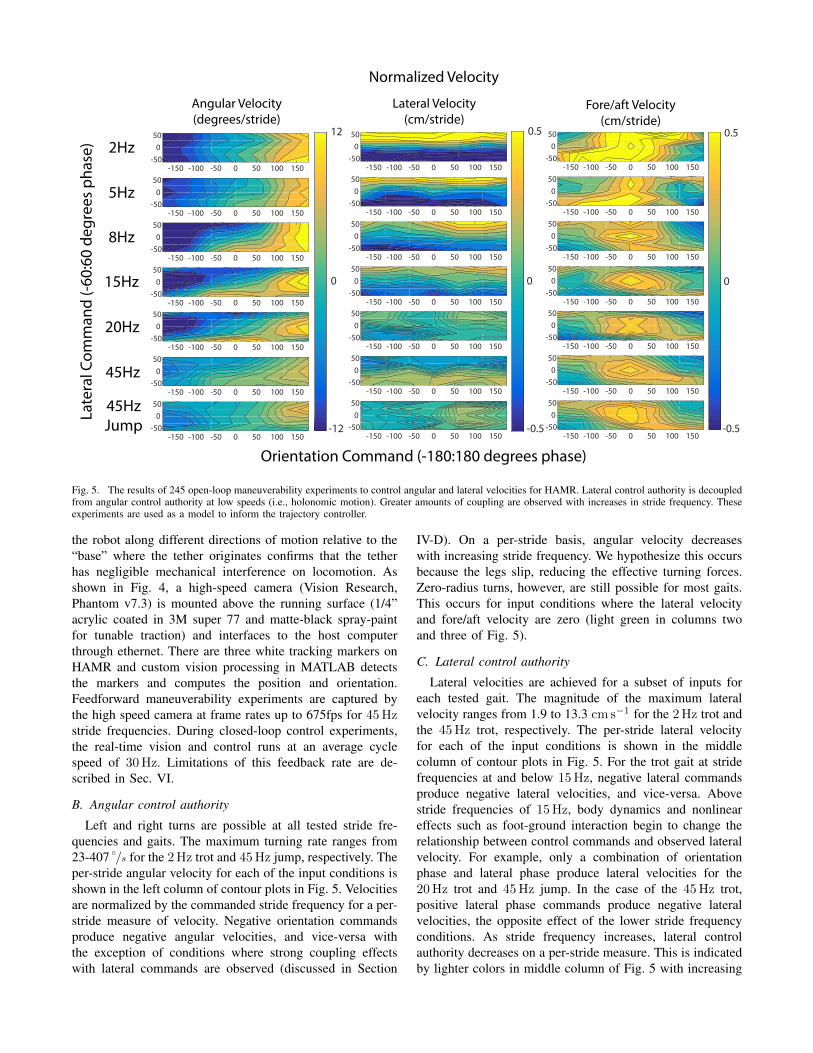
Fig. 5. The results of 245 open-loop maneuverability experiments to control angular and lateral velocities for HAMR. Lateral control authority is decoupledfrom angular control authority at low speeds (i.e., holonomic motion). Greater amounts of coupling are observed with increases in stride frequency. Theseexperiments are used as a model to inform the trajectory controller.
the robot along different directions of motion relative to the“base” where the tether originates confirms that the tetherhas negligible mechanical interference on locomotion. Asshown in Fig. 4, a high-speed camera (Vision Research,Phantom v7.3) is mounted above the running surface (1/4”acrylic coated in 3M super 77 and matte-black spray-paintfor tunable traction) and interfaces to the host computerthrough ethernet. There are three white tracking markers onHAMR and custom vision processing in MATLAB detectsthe markers and computes the position and orientation.Feedforward maneuverability experiments are captured bythe high speed camera at frame rates up to 675fps for 45Hzstride frequencies. During closed-loop control experiments,the real-time vision and control runs at an average cyclespeed of 30Hz. Limitations of this feedback rate are de-scribed in Sec. VI.
B. Angular control authority
Left and right turns are possible at all tested stride fre-quencies and gaits. The maximum turning rate ranges from23-407 ◦
/s for the 2Hz trot and 45Hz jump, respectively. Theper-stride angular velocity for each of the input conditions isshown in the left column of contour plots in Fig. 5. Velocitiesare normalized by the commanded stride frequency for a per-stride measure of velocity. Negative orientation commandsproduce negative angular velocities, and vice-versa withthe exception of conditions where strong coupling effectswith lateral commands are observed (discussed in Section
IV-D). On a per-stride basis, angular velocity decreaseswith increasing stride frequency. We hypothesize this occursbecause the legs slip, reducing the effective turning forces.Zero-radius turns, however, are still possible for most gaits.This occurs for input conditions where the lateral velocityand fore/aft velocity are zero (light green in columns twoand three of Fig. 5).
C. Lateral control authority
Lateral velocities are achieved for a subset of inputs foreach tested gait. The magnitude of the maximum lateralvelocity ranges from 1.9 to 13.3 cm s−1 for the 2Hz trot andthe 45Hz trot, respectively. The per-stride lateral velocityfor each of the input conditions is shown in the middlecolumn of contour plots in Fig. 5. For the trot gait at stridefrequencies at and below 15Hz, negative lateral commandsproduce negative lateral velocities, and vice-versa. Abovestride frequencies of 15Hz, body dynamics and nonlineareffects such as foot-ground interaction begin to change therelationship between control commands and observed lateralvelocity. For example, only a combination of orientationphase and lateral phase produce lateral velocities for the20Hz trot and 45Hz jump. In the case of the 45Hz trot,positive lateral phase commands produce negative lateralvelocities, the opposite effect of the lower stride frequencyconditions. As stride frequency increases, lateral controlauthority decreases on a per-stride measure. This is indicatedby lighter colors in middle column of Fig. 5 with increasing

stride frequency.
D. Angular and lateral coupling
Due to nonlinear effects of body and transmission dynam-ics and foot-ground interaction at high stride frequencies,there is substantial coupling between angular and lateralvelocities at high stride frequencies. At stride frequenciesat and below 5Hz, angular and lateral velocity commandscan be considered to be decoupled, as shown in the left andmiddle columns of Fig. 5. This means that a change in orien-tation command only produces a change in angular velocity(vertical lines in the first column of Fig. 5). Similarly, achange in lateral command only produces a change in lateralvelocity (horizontal lines in the second column of Fig. 5).Above stride frequencies of 5Hz, there is coupling in theobserved angular and lateral velocities for most orientationand lateral commands. If there is no lateral command,however, orientation control is approximately linear withphase.
E. Fore/aft velocity
The right column of Fig. 5 shows the normalized fore/aftvelocity of HAMR for the given input conditions. Forwardvelocity generally decreases as phase inputs deviate from thenominal phasing. In extreme cases, there are negative fore/aftvelocities (blue regions of third column in Fig. 5). Thisoccurs because the leg trajectories reverse direction and/ormove only in the lateral direction for large input orientationand lateral commands. In a controller, these reverse motionscan be incorporated or penalized for purposes of preventingbackward motions. For simplicity of the trajectory planningin this paper, rearward motions are penalized and onlyforward trajectories are considered.
V. CONTROL EXPERIMENTS
The open-loop maneuverability results from the previoussections are used to develop a controller for trajectoryfollowing. The following sections describe the controllerarchitecture and compare the controllers at low and highspeeds. This control scheme is motivated by simplicity forfuture autonomy and overcomes complexities of systemdynamics and ground contact.
A. Controller architecture
A block diagram of the controller architecture is shownin Fig. 6. Feedback for the controller is provided from thehigh-speed camera mounted above HAMR as shown in Fig.4. Each image is processed using custom tracking scriptswith the image processing and computer vision toolboxin MATLAB. The image processing for the position andorientation (“pose”), as well as the control input calculationsare done on the host computer. Control inputs are then sentto the xPC target machine for low-level signal generation.Control inputs are determined separately for lateral andangular velocities, each with their own gains.
Given the desired state, control inputs are calculated usinga proportional controller for both the heading and lateral
Camera
HAMR-VI High VoltageAmpli�er DAQ
Lateral Velocity Controller
Drive SignalWaveform
Generation
Angular Velocity Controller
OptionalManeuverability
Model
poseEstimation
xPC Target (5kHz)
Host PC (30Hz)
DesiredState
Fig. 6. Architecture of the controller and experimental setup. Phasecommands from the lateral and angular velocity controllers can be applieddirectly to the drive signals or the maneuverability model can be used todetermine phasing based on the open-loop maneuverability tests.
position. Integral and derivative gains are omitted due towindup considerations, low feedback rate, and the discretenature of taking steps which leads to noisy derivatives. Thecontrol inputs can either be directly sent as the actuatorphasing (no model) for the lateral and orientation command,or the results from the maneuverability experiments can beused as a lookup table (model) to find the commands toachieve the desired angular and lateral velocities.
B. Low speed overhead controller
Before more complex trajectories are run, step inputs arecommanded to observe the error dynamics. In these tests,the robot starts at a position and orientation with non-zerolateral and heading errors (elat = 6.0 cm and eθ = 30◦).The performance for the controller without (Fig. 7a, c) andwith (Fig. 7b, d) the model are compared for the 2Hz trot.At low speeds, the performance with and without the modelis similar. In steady-state∗, the RMS errors are 0.3BL and0.4BL for position and 1.6◦ and 4.5◦ for orientation with and
∗Steady-state is considered to be when the robot is within ±0.5 bodywidths away from the trajectory and has a heading error within ±10◦.
2Hz Trot 45Hz Jump
45Hz Trot Reference Trajectory
y-po
sitio
n(m
m)
Orie
ntat
ion
Erro
r(d
egre
es)
x-position (mm)
Late
ral E
rror
(mm
)
No Model Model
0 100 200 300 400-60-40-20
020
0 50 100 150 200 250 300 350
x-position (mm)
-50
0
50
0 50 100 150 200 250 300 350
0
50
100
0 100 200 300-150
-100
-50
0
0 50 100 150 200 250 300 350-100
-50
0
50
0 50 100 150 200 250 300 350
0
50
100
x-position (mm) x-position (mm)(a) (b)
(c) (d)
HAMRTrajectory Start
Trajectory End
Fig. 7. Step input for low frequency and high frequency gaits for thecontroller with and without a maneuverability model. The controller fails forhigh frequency gaits without a model. The robot converges to the referencetrajectory with the model, but does so in a longer distance for the 45Hzgaits compared to the 2Hz trot gait with and without a model.
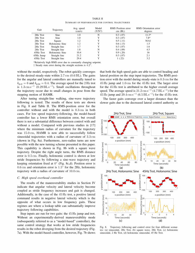
TABLE IISUMMARY OF PERFORMANCE FOR CONTROL TRAJECTORIES
Gait Trajectory Avg. speed(cm/s)
Model(Y/N?)
RMS Position errorcm (BL)
RMS Orientation errordegrees
2Hz Trot Sine 1.0 N 0.3 (.07) 11.3*2Hz Trot Sine 1.0 Y 0.3 (.07) 7.8*2Hz Trot Square 1.2 Y 0.5 (.11) N/A†2Hz Trot Holonomic Sine 1.2 Y 0.6 (.13) 1.52Hz Trot Straight line 1.7 Y 0.3 (.07) 1.62Hz Trot Straight line 1.8 N 0.4 (.09) 4.5
45Hz Trot Holonomic Sine 10.4 Y 0.9 (.20) 1645Hz Jump Straight line 21.2 Y 0.3 (.07) 2.145Hz Trot Straight line 29.4 Y 1 (.22) 3.2
*Relatively high RMS error due to constantly changing setpoint.† Steady state error during the straight sections is 4.2◦.
without the model, respectively. The robot quickly convergesto the desired steady-state within 2.7 cm (0.6BL). The gainsfor the angular and lateral controllers are manually tuned tokp,or = 6 and kp,lat = 0.4. The average speed for the 2Hz trotis 1.3 cm s−1 (0.29BL s−1). Small oscillations throughoutthe trajectory occur due to small changes in pose from thestepping motion of HAMR.
After tuning straight-line walking, sine-wave trajectoryfollowing is tested. The results of these tests are shownin Fig. 8 and Table II. The RMS-position error for thecontroller without and with the model is 0.3 cm in bothcases. For low speed trajectory-following, the model-basedcontroller has a lower RMS orientation error, but overallthere is not a substantial difference between control with andwithout a model. Compared with previous studies in [17]where the minimum radius of curvature for the trajectorywas 15.0 cm, HAMR is now able to successfully followsinusoidal trajectories with a radius of curvature of 3.3 cm(shown in Fig. 8a). Furthermore, zero-radius turns are nowpossible with the new turning scheme presented in this paper.This capability is shown in Fig. 8b with a square wavetrajectory. Despite the right angle turns, the RMS distanceerror is 0.5 cm. Finally, holonomic control is shown at lowstride frequencies by following a sine-wave trajectory andkeeping orientation fixed at 0◦ (Fig. 8c,d). Position error is0.6 cm and orientation error is 1.5◦ for the 2Hz, holonomictrajectory with a radius of curvature of 10.0 cm.
C. High speed overhead controller
The results of the maneuverability studies in Section IVindicate that angular velocity and lateral velocity becomecoupled as stride frequency increases and gait is changed.Additionally, in the case of the 45Hz trot, a positive lateralcommand results in negative lateral velocity which is theopposite of what occurs in low frequency gaits. Theseregimes are where a lookup table can substantially improvetrajectory following capabilities.
Step inputs are run for two gaits: the 45Hz jump and trot.Without an experimentally-derived maneuverability mode(subsequently referred to as a “model-based” controller), thesame control strategy that works at low stride frequenciesresults in the robot diverging from the desired trajectory (Fig.7a). With the model-based controller, however, Fig. 7b shows
that both the high speed gaits are able to control heading andlateral position on the step input trajectories. The RMS posi-tion error with the model during steady-state is 0.3 cm for the45Hz jump and 1.0 cm for the 45Hz trot. The larger errorfor the 45Hz trot is attributed to the higher overall averagespeed. The average speed is 21.2 cm s−1 (4.7BL s−1) for the45Hz jump and 29.4 cm s−1 (6.5BL s−1) for the 45Hz trot.
The faster gaits converge over a larger distance than theslower gaits due to the decreased lateral control authority as
2Hz Trot, Sine
100 200 300 400x-position (mm)
-100
0
100
y-po
sitio
n (m
m)
0 20 40 60 80Time (seconds)
0
5
10
Dis
tanc
e Er
ror (
mm
)
(a) (b)
2Hz Trot, Square
(c)
100 200 300 400x-position (mm)
-100
0
100
y-po
sitio
n (m
m)
0 10 20 30 40 50Time (seconds)
0
5
10
15
Dis
tanc
e Er
ror (
mm
)
(d)
2Hz Trot, Holonomic Sine
100 200 300 400x-position (mm)
-100
0
100
y-po
sitio
n (m
m)
0 10 20 30Time (seconds)
0
5
10
15
Dis
tanc
e Er
ror (
mm
)
Reference Trajectory Robot Position Robot Error
0 1 2 3 40
10
20
45Hz Trot, Holonomic Sine
x-position (mm)
y-po
sitio
n (m
m)
Time (seconds)
Dis
tanc
e Er
ror (
mm
)
HAMR
100 200 300 400-100
0
100
Fig. 8. Trajectory following and control error for four different scenar-ios: (a) sinusoidal, 2Hz Trot, (b) square wave, 2Hz Trot, (c) holonomicsinusoidal, 2 Hz Trot, (d) holonomic sinusoidal, 45 Hz Trot.

50 100 150 200 250 300 350 400 450x-position (mm)
-50
0
50
100y-
posi
tion
(mm
)45Hz Trot45Hz Jump
ObstaclesReference Trajectory
HAMR-VI
Start End
0 1 2 3 4 5 6 7Time (seconds)
-50
0
50
Orie
ntat
ion
Erro
r (de
gree
s)
Fig. 9. HAMR navigates through an obstacle course using a model-based controller for high speed gaits. Despite high speed gaits and rapidchanges in the commanded position and orientation, the robot is still ableto successfully navigate the obstacle course.
mentioned in Sec. IV. The gait that takes the longest distanceto converge is the 45Hz trot which takes 17.1 cm (3.8BL)to reach steady-state. For comparison, it takes only 2.7 cm(0.6BL) to reach steady-state for the 2Hz trot. Despitethe longer convergence distance, we are able to performholonomic control with up to 0.9 cm (0.2BL) accuracy asshown in Fig. 8d and Table II at a speed of 10.4 cm s−1
(2.3BL s−1).
D. High speed obstacle course
After characterizing the step input dynamics for the highspeed controller, the robot is run through an obstacle courseto demonstrate high speed trajectory following using themodel-based controller. The obstacle course is shown in Fig.9. A trajectory is planned using a gradient descent algorithmand HAMR is able to successfully navigate with both the45Hz trot and jump using the model-based controller asshown in the accompanying supplemental video.
VI. DISCUSSION
Due to highly nonlinear effects of body dynamics and foot-ground interaction of the robot, angular and lateral controldiffers based on the commanded gait. As the gait is changed(e.g., increasing stride frequency or changing from a trotto a jump) the nature of the coupling between angular andlateral velocities changes in both the magnitude and shape.Additionally, the lateral control authority decreases withincreasing stride frequency. It is hypothesized that this isdue to effects of body dynamics and foot-ground interactions(e.g., slipping). To capture these effects, an experimental
maneuverability model is found to be useful to map the inputleg phasing to output body velocities.
Accuracy of trajectory control at high frequencies isaffected by the relatively low feedback rate (30Hz) com-pared to low frequencies (1.5 commands per cycle vs. 15commands per cycle). The relatively low feedback rate isa limitation of the camera and vision processing. With theaddition of onboard sensing as demonstrated in [16], higherfeedback rates of 100Hz with sensors such as the ADNS-3530 optical mouse sensor can improve the performance ofthe high speed trajectory controller. The controller also ben-efits from being easy to implement onboard an autonomousversion of HAMR with actuator phase easily controlled bya microcontroller clock.
VII. CONCLUSIONS AND FUTURE WORK
A maneuverability strategy based on leg swing-stancephasing is presented and applied to a trajectory controller forlow and high speed running for HAMR-VI. Feedback controlfor lateral and angular position is achieved at speeds rangingfrom 1.0 to 23.3 cm s−1 (0.22-6.5BL s−1). In addition toimproving the turning radius of HAMR from 15cm to a zero-raidus turn at low stride frequencies, we also demonstratea significant increase in average speed during trajectorycontrol on HAMR from 0.68 cm s−1 to 29.4 cm s−1, morethan 30 times faster compared to prior work ([16], [17]).Furthermore, we perform aggressive holonomic trajectoryfollowing and through an obstacle course in a which wasnot possible due to the limited control authority of the priorrobot and controller designs.
This controller will be applied to future autonomousversions of HAMR that have onboard power and controlelectronics. Previous versions of HAMR in [16] used aMEMS gyroscope and optical mouse sensor to control posi-tion and orientation. Bruhwiler et al. implemented a simpleorientation controller but the robot had a limited turningradius, stride frequency, gait choice, and no lateral controlauthority. With the addition of the model-based controllerpresented here, more complex trajectories can be followedmore accurately.
Presumably, complex or textured terrains will have aneffect on the performance of the trajectory controller. Futurestudies should examine these effects and improve foot-ground interactions to achieve faster lateral and turningspeeds, especially at high stride frequencies. The benefitof incorporating the experimental model described in thispaper is that a simple calibration run can eliminate theneed for complex modeling of terramechanics when movingto control experiments on different terrains. In addition totracking kinematics, force measurements during heading andlateral maneuvers can help determine foot designs that aresuitable for reducing slippage and achieving faster turns.Additionally, the controller can be improved by applyingother controller architectures such as LQR optimal controlby fitting a dynamic model to the experimental data.
Beyond HAMR, using leg phasing for holonomic tra-jectory control can be extended to other legged robots.

Specifically, robots like OctoRoACH or DASH [9], [12] thathave a lateral DOF can apply a similar, phase-based holo-nomic controller. Furthermore, we show that an experimentalcharacterization can be valuable for informing a controllerto improve trajectory following performance over a range ofstride frequencies.
ACKNOWLEDGMENTS
Thank you to all members of the Harvard MicroroboticsLab for invaluable discussions. This work is funded bythe Wyss Institute for Biologically Inspired Engineeringand the National Science Foundation under Grant NumberDGE1144152. Any opinion, findings, and conclusions orrecommendations expressed in this material are those ofthe authors and do not necessarily reflect the views of theNational Science Foundation. In addition, the prototypeswere enabled by equipment supported by the ARO DURIPprogram (award #W911NF-13-1-0311).
REFERENCES
[1] J. C. Spagna, D. I. Goldman, P.-C. Lin, D. E. Koditschek, and R. J.Full, “Distributed mechanical feedback in arthropods and robots sim-plifies control of rapid running on challenging terrain,” Bioinspiration& biomimetics, vol. 2, no. 1, p. 9, 2007.
[2] J. Camhi and E. Johnson, “High-frequency steering maneuvers medi-ated by tactile cues: antennal wall-following in the cockroach,” Journalof Experimental Biology, vol. 202, no. 5, pp. 631–643, 1999.
[3] S. Sponberg and R. Full, “Neuromechanical response of musculo-skeletal structures in cockroaches during rapid running on roughterrain,” Journal of Experimental Biology, vol. 211, no. 3, pp. 433–446, 2008.
[4] J. Schmitt, M. Garcia, R. Razo, P. Holmes, and R. J. Full, “Dynamicsand stability of legged locomotion in the horizontal plane: a test caseusing insects,” Biological cybernetics, vol. 86, no. 5, pp. 343–353,2002.
[5] D. Zarrouk, A. Pullin, N. Kohut, and R. Fearing, “Locomotion of in-plane robot with continuously sliding feet,” in Proc. CLAWAR, 2014.
[6] U. Saranli, M. Buehler, and D. E. Koditschek, “RHex: A simple andhighly mobile hexapod robot,” The International Journal of RoboticsResearch, vol. 20, no. 7, pp. 616–631, 2001.
[7] H.-W. Park, P. M. Wensing, and S. Kim, “Online planning forautonomous running jumps over obstacles in high-speed quadrupeds,”in 2015 Robotics Science and Systems Conference, Sapienza Universityof Rome, July 13-17, 2015, pp. 1–9.
[8] M. Spenko, G. Haynes, J. Saunders, M. Cutkosky, A. Rizzi, R. Full,and D. Koditschek, “Biologically inspired climbing with a hexapedalrobot,” J. of Field Robotics, vol. 25, no. 4-5, pp. 223–242, 2008.
[9] A. O. Pullin, N. J. Kohut, D. Zarrouk, and R. S. Fearing, “Dynamicturning of 13 cm robot comparing tail and differential drive,” in IEEEIntl. Conf. on Robotics and Automation. IEEE, 2012, pp. 5086–5093.
[10] K. Karydis, Y. Liu, I. Poulakakis, and H. G. Tanner, “Navigationof miniature legged robots using a new template,” in Control andAutomation (MED), 2015 23th Mediterranean Conference on. IEEE,2015, pp. 1112–1117.
[11] A. M. Hoover, E. Steltz, and R. S. Fearing, “RoACH: An autonomous2.4g crawling hexapod robot,” in IEEE/RSJ Intl. Conf. on IntelligentRobots and Systems, 2008, pp. 22–26.
[12] P. Birkmeyer, K. Peterson, and R. S. Fearing, “DASH: A dynamic 16ghexapedal robot,” in IEEE/RSJ Intl. Conf. on Intelligent Robots andSystems. IEEE, 2009, pp. 2683–2689.
[13] A. T. Baisch, O. Ozcan, B. Goldberg, D. Ithier, and R. J. Wood, “Highspeed locomotion for a quadrupedal microrobot,” The InternationalJournal of Robotics Research, p. 0278364914521473, 2014.
[14] A. T. Baisch and R. J. Wood, “Pop-up assembly of a quadrupedalambulatory microrobot,” in Intelligent Robots and Systems (IROS),2013 IEEE/RSJ International Conference on. IEEE, 2013, pp. 1518–1524.
[15] B. F. Seitz, B. Goldberg, N. Doshi, O. Ozcan, D. L. Christensen, E. W.Hawkes, M. R. Cutkosky, and R. J. Wood, “Bio-inspired mechanismsfor inclined locomotion in a legged insect-scale robot,” in Roboticsand Biomimetics (ROBIO), 2014 IEEE International Conference on.IEEE, 2014, pp. 791–796.
[16] R. Bruhwiler, B. Goldberg, N. Doshi, O. Ozcan, N. Jafferis, M. Karpel-son, and R. J. Wood, “Feedback control of a legged microrobot withon-board sensing,” in Intelligent Robots and Systems (IROS), 2015IEEE/RSJ International Conference on. IEEE, 2015, pp. 5727–5733.
[17] O. Ozcan, A. T. Baisch, and R. J. Wood, “Design and feedback controlof a biologically-inspired miniature quadruped,” in 2013 IEEE/RSJInternational Conference on Intelligent Robots and Systems. IEEE,2013, pp. 1438–1444.
[18] N. Doshi, B. Goldberg, R. Sahai, N. Jafferis, D. Aukes, and R. J.Wood, “Model driven design for flexure-based microrobots,” in In-telligent Robots and Systems (IROS), 2015 IEEE/RSJ InternationalConference on. IEEE, 2015, pp. 4119–4126.
[19] R. J. Full and C. F. Herreid, “Fiddler crab exercise: the energetic costof running sideways,” J. exp. Biol, vol. 109, pp. 141–161, 1984.