high speed nano-scale positioning using a piezoelectric tube actuator with active shunt control
TRANSCRIPT

High speed nano-scale positioning usinga piezoelectric tube actuator withactive shunt control
S. Aphale, A.J. Fleming and S.O.R. Moheimani
Abstract: Piezoelectric tube scanners are the actuators of choice in scanning probe microscopy.These nanopositioners exhibit a dominant first resonant mode that is excited due to harmonicsof the input scan signal. This introduces errors in the scan obtained. The presence of this resonantmode limits the upper bound of a triangular scan rate to around 1/100th of the first mechanicalresonance frequency. Passive and active shunts have shown to damp this resonant mode substan-tially and improve scan performance. Sensorless active shunts optimised using H2 and H1 tech-niques, is designed. These shunts reduce the amplitude of the first resonant peak of a prototypetube nanopositioner by 24 dB. A triangle wave input is used to test the improvement in scan per-formance due to the damping achieved by these active shunts. Analysis shows that damping theresonant mode in such fashion reduces the scan error by five times.
1 Introduction
Piezoelectric tube scanners were first reported in Binnig andSmith [1] for use in scanning tunnelling microscopes [2].They were found to provide a higher positioning resolutionand greater bandwidth than traditional tripod positionerswhile being simple enough to manufacture and easier tointegrate into a microscope. Owing to their excellentdisplacement resolution, down to 10 pm, piezoelectrictube scanners are a key component in scanning probemicroscopes [3], nanofabrication systems [4, 5] and nano-manipulation devices [6].In many applications, piezoelectric tubes are designed
with large length-to-diameter ratios; this provides a largedeflection range but imposes low mechanical resonancefrequencies. In nanometer precision raster scanningapplications, such as SPM, the maximum triangular scanrate is limited to around 1/100th of the first resonancefrequency of the tube. To illustrate the problem, considera typical piezoelectric tube with maximum lateral deflectionof 100 mm and a resonance frequency of 700 Hz. For anSPM, this equates to more than 60 s of image acquisitiontime (at VGA resolution) and severe throughput limitationsin nanomanipulation and fabrication processes. The presentwork aims to damp the first lateral resonant mode and thusreduce the system response to external noise and inducedvibration.Feedforward and signal compensation approaches to
vibration control have been studied extensively as theirimplementation requires no additional hardware or sensorsand is noise efficient. It should be considered, however,that additional hardware such as displacement sensors anddigital signal processors are required to identify the
# The Institution of Engineering and Technology 2007
doi:10.1049/mnl:20065075
Paper first received 17th January 2007
The authors are with School of Electrical Engineering and Computer Science,University of Newcastle, Callaghan, NSW 2308 Australia
E-mail: [email protected]
Micro & Nano Letters, 2007, 2, (1), pp. 9–12
behaviour of each tube prior to implementation. In addition,although feedforward techniques do not add sensor noise tothe control signal, they cannot provide any immunity toexternally induced vibration. A technique for designingoptimal linear feedforward compensators was presented inCroft et al. [7], then later extended to incorporate a PDfeedback controller [8]. In these works, the authors identifythe main limitation to performance as being modellingerror. Other model-based feedforward approaches include[9, 10] and [11].
Feedback techniques can provide excellent low-frequency tracking performance but require an expensiveand possibly difficult-to-integrate displacement sensor.Such techniques are most applicable to large scan rangeswhere sensor noise does not significantly degrade imagequality, or at low speeds where the noise bandwidth canbe significantly reduced. Good tracking of a 5 Hz trianglewave while maintaining robustness to non-linearity waspresented in Salapaka et al. [12].
In Fleming et al. [13] a new vibration control technique,passive shunt damping, was applied to damp the firstmechanical mode of a piezoelectric tube scanner. In thisapproach, an LRC impedance was connected to thepiezoelectric transducer. When subject to deflection, thecharge generated in the transducer flows through theexternal shunt impedance developing a counteractivevoltage which can be optimised to result in significantvibration damping [14]. Shunt damping does not require adisplacement sensor, is simple to implement and can beimplemented with (essentially noise free) passivecomponents. This paper extends the previous passivetechniques to active and optimal shunt impedances thatcan damp a higher number of modes with greaterperformance.
2 Piezoelectric tube scanner
As shown in Fig. 1b, a piezoelectric tube scanner comprisesof a hollow tube of radially poled piezoelectric materialfixed at one end and free to deflect at the other. An electric
9
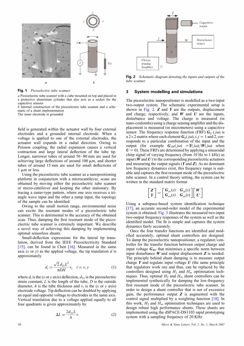
field is generated within the actuator wall by four externalelectrodes and a grounded internal electrode. When avoltage is applied to one of the external electrodes, theactuator wall expands in a radial direction. Owing toPoisson coupling, the radial expansion causes a verticalcontraction and large lateral deflection of the tube tip.Longer, narrower tubes of around 50–80 mm are used forachieving large deflections of around 100 mm, and shortertubes of around 15 mm are used for small deflections of1 mm or less.
Using the piezoelectric tube scanner as a nanopositioningplatform in conjunction with a microcantilever, scans areobtained by moving either the piezoelectric tube scanneror micro-cantilever and keeping the other stationary. Bytracing a raster-type pattern, where one axis receives a tri-angle wave input and the other a ramp input, the topologyof the sample can be identified.
Owing to the small motion range, environmental noisecan excite the resonant modes of a piezoelectric tubescanner. This is detrimental to the accuracy of the obtainedscan. Thus, damping the first resonant mode of the piezo-electric tube scanner is extremely important. We describea novel way of achieving this damping by implementingoptimal sensorless shunts.
Small-deflection expressions for the lateral tip trans-lation, derived from the IEEE Piezoelectricity Standard[15], can be found in Chen [16]. Measured in the sameaxis (x or y) as the applied voltage, the tip translation d isapproximately
di ¼
ffiffiffi2
pd31L
2
pDHvi i ¼ x; y ð1Þ
where di is the (x or y axis) deflection, d31 is the piezoelectricstrain constant, L is the length of the tube, D is the outsidediameter, h is the tube thickness and vi is the (x or y axis)electrode voltage. Tip deflection can be doubled by applyingan equal and opposite voltage to electrodes in the same axis.Vertical translation due to a voltage applied equally to allfour quadrants is given approximately by
DL ¼2d31L
hv ð2Þ
Fig. 1 Piezoelectric tube scanner
a Piezoelectric tube scanner with a cube mounted on top and placed ina protective aluminium cylinder that also acts as a socket for thecapacitive sensorsb Internal construction of the piezoelectric tube scanner and a sche-matic of a shunt implementationThe inner electrode is grounded
10
3 System modelling and simulations
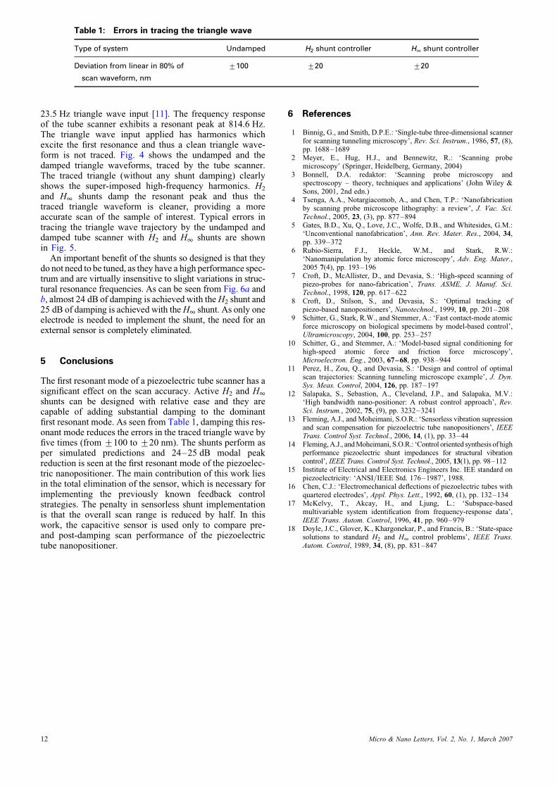
The piezoelectric nanopositioner is modelled as a two-inputtwo-output system. The schematic experimental setup isshown in Fig. 2. Z and Y are the outputs, displacementand charge, respectively, and W and U are the inputs,disturbance and voltage. The charge is measured (innano-coulombs) using a charge sensing amplifier and the dis-placement is measured (in micrometers) using a capacitivesensor. The frequency response function (FRF) Gij ( jv) isa 2�2matrix where each elementGij( jv), i, j ¼ 1 and 2, cor-responds to a particular combination of the input and theoutput (for example GYW( jv) ¼Y( jv)/W( jv) whenU ¼ 0). These FRFs are determined by applying a sinusoidalchirp signal of varying frequency (from 10 Hz to 1 kHz) asinput (W andU ) to the corresponding piezoelectric actuatorsand measuring the output signals (Y and Z). As no dominantlow frequency dynamics exist, this frequency range is suit-able and captures the first resonant mode of the piezoelectrictube scanner. In a control theory setting, the system can bewritten in the standard matrix format
Z
Y
� �¼
GzwðsÞ GzuðsÞ
GywðsÞ GyuðsÞ
� �W
U
� �
Using a subspace-based system identification technique[17], an accurate second-order model of the experimentalsystem is obtained. Fig. 3 illustrates the measured two-inputtwo-output frequency responses of the system as well as theidentified model. The fit is simple and captures the systemdynamics fairly accurately.Once the four transfer functions are identified and mod-
elled accurately, optimal shunt controllers are designed.To damp the piezoelectric nanopositioner, a regulator/con-troller for the transfer function between output charge andinput voltage GYU that minimises a specific norm betweeninput disturbance W and output displacement Z is needed.The principle behind shunt damping is to measure outputcharge Y and regulate input voltage U (the same principlethat regulators work on) and thus, can be replaced by thecontrollers designed using H2 and H1 optimisation tech-niques. Thus, optimal H2 and H1 shunt controllers can beimplemented synthetically for damping the low-frequencyfirst resonant mode of the piezoelectric tube scanner. Inorder to design a shunt controller that is not of excessivegain, the performance output Z is augmented with thecontrol signal multiplied by a weighting function [18]. Inthis work, H2 and H1 optimisation techniques are used todesign robust high performance shunts. These shunts areimplemented using the dSPACE-DS1103 rapid prototypingsystem with a sampling frequency of 20 KHz.
Fig. 2 Schematic diagram denoting the inputs and outputs of thetube scanner
Micro & Nano Letters, Vol. 2, No. 1, March 2007

Though two electrodes (2y and y) are used in the exper-imental setup, it should be noted that only one of the elec-trodes is connected to the shunt and the other electrode isused to introduce a scanning waveform and to evaluatethe damping performance. A penalty in using the damping
Fig. 3 Magnitude and phase response of the actual (- -) and themodelled (—) tube nanopositioner system with inputs, disturbance(W ) and voltage (U ) and outputs, displacement (Z ) and charge (Y ).
Note that the model captures the dynamics of the system with veryhigh precision
Fig. 4 Triangle waveforms traced by the undamped tube scanneragainst the ones traced by the tube scanner damped using H2 shuntand H1 shunt
Micro & Nano Letters, Vol. 2, No. 1, March 2007
network is that only one electrode can be used for scanning,thus, the scanning range is reduced by half.
4 Experimental results
To evaluate the performance of the shunts designed, thepiezoelectric tube scanner was made to trace a 16 Vpk,
Fig. 5 Plot of deviation from linear in 80% of scan waveform
Note that the undamped deviation is plotted on a scale of +0.1 mmwhile the damped H2 and H1 deviations are plotted on a scaleof +0.02 mm
Fig. 6 Undamped and damped transfer functions from the inputdisturbance W (in volts) to the output displacement Z (measuredusing a capacitive sensor with a gain of 0.1 V/mm)
a Damping achieved by H2 optimised shuntb Damping achieved by H1 optimised shunt
11
12
Table 1: Errors in tracing the triangle wave
Type of system Undamped H2 shunt controller H1 shunt controller
Deviation from linear in 80% of
scan waveform, nm
+100 +20 +20
23.5 Hz triangle wave input [11]. The frequency responseof the tube scanner exhibits a resonant peak at 814.6 Hz.The triangle wave input applied has harmonics whichexcite the first resonance and thus a clean triangle wave-form is not traced. Fig. 4 shows the undamped and thedamped triangle waveforms, traced by the tube scanner.The traced triangle (without any shunt damping) clearlyshows the super-imposed high-frequency harmonics. H2
and H1 shunts damp the resonant peak and thus thetraced triangle waveform is cleaner, providing a moreaccurate scan of the sample of interest. Typical errors intracing the triangle wave trajectory by the undamped anddamped tube scanner with H2 and H1 shunts are shownin Fig. 5.
An important benefit of the shunts so designed is that theydo not need to be tuned, as they have a high performance spec-trum and are virtually insensitive to slight variations in struc-tural resonance frequencies. As can be seen from Fig. 6a andb, almost 24 dB of damping is achieved with theH2 shunt and25 dB of damping is achieved with theH1 shunt. As only oneelectrode is needed to implement the shunt, the need for anexternal sensor is completely eliminated.
5 Conclusions
The first resonant mode of a piezoelectric tube scanner has asignificant effect on the scan accuracy. Active H2 and H1
shunts can be designed with relative ease and they arecapable of adding substantial damping to the dominantfirst resonant mode. As seen from Table 1, damping this res-onant mode reduces the errors in the traced triangle wave byfive times (from +100 to +20 nm). The shunts perform asper simulated predictions and 24–25 dB modal peakreduction is seen at the first resonant mode of the piezoelec-tric nanopositioner. The main contribution of this work liesin the total elimination of the sensor, which is necessary forimplementing the previously known feedback controlstrategies. The penalty in sensorless shunt implementationis that the overall scan range is reduced by half. In thiswork, the capacitive sensor is used only to compare pre-and post-damping scan performance of the piezoelectrictube nanopositioner.
6 References
1 Binnig, G., and Smith, D.P.E.: ‘Single-tube three-dimensional scannerfor scanning tunneling microscopy’, Rev. Sci. Instrum., 1986, 57, (8),pp. 1688–1689
2 Meyer, E., Hug, H.J., and Bennewitz, R.: ‘Scanning probemicroscopy’ (Springer, Heidelberg, Germany, 2004)
3 Bonnell, D.A. redaktor: ‘Scanning probe microscopy andspectroscopy – theory, techniques and applications’ (John Wiley &Sons, 2001, 2nd edn.)
4 Tsenga, A.A., Notargiacomob, A., and Chen, T.P.: ‘Nanofabricationby scanning probe microscope lithography: a review’, J. Vac. Sci.Technol., 2005, 23, (3), pp. 877–894
5 Gates, B.D., Xu, Q., Love, J.C., Wolfe, D.B., and Whitesides, G.M.:‘Unconventional nanofabrication’, Ann. Rev. Mater. Res., 2004, 34,pp. 339–372
6 Rubio-Sierra, F.J., Heckle, W.M., and Stark, R.W.:‘Nanomanipulation by atomic force microscopy’, Adv. Eng. Mater.,2005 7(4), pp. 193–196
7 Croft, D., McAllister, D., and Devasia, S.: ‘High-speed scanning ofpiezo-probes for nano-fabrication’, Trans. ASME, J. Manuf. Sci.Technol., 1998, 120, pp. 617–622
8 Croft, D., Stilson, S., and Devasia, S.: ‘Optimal tracking ofpiezo-based nanopositioners’, Nanotechnol., 1999, 10, pp. 201–208
9 Schitter, G., Stark, R.W., and Stemmer, A.: ‘Fast contact-mode atomicforce microscopy on biological specimens by model-based control’,Ultramicroscopy, 2004, 100, pp. 253–257
10 Schitter, G., and Stemmer, A.: ‘Model-based signal conditioning forhigh-speed atomic force and friction force microscopy’,Microelectron. Eng., 2003, 67–68, pp. 938–944
11 Perez, H., Zou, Q., and Devasia, S.: ‘Design and control of optimalscan trajectories: Scanning tunneling microscope example’, J. Dyn.Sys. Meas. Control, 2004, 126, pp. 187–197
12 Salapaka, S., Sebastion, A., Cleveland, J.P., and Salapaka, M.V.:‘High bandwidth nano-positioner: A robust control approach’, Rev.Sci. Instrum., 2002, 75, (9), pp. 3232–3241
13 Fleming, A.J., and Moheimani, S.O.R.: ‘Sensorless vibration supressionand scan compensation for piezoelectric tube nanopositioners’, IEEETrans. Control Syst. Technol., 2006, 14, (1), pp. 33–44
14 Fleming,A.J., andMoheimani, S.O.R.: ‘Control oriented synthesis of highperformance piezoelectric shunt impedances for structural vibrationcontrol’, IEEE Trans. Control Syst. Technol., 2005, 13(1), pp. 98–112
15 Institute of Electrical and Electronics Engineers Inc. IEE standard onpiezoelectricity: ‘ANSI/IEEE Std. 176–1987’, 1988.
16 Chen, C.J.: ‘Electromechanical deflections of piezoelectric tubes withquartered electrodes’, Appl. Phys. Lett., 1992, 60, (1), pp. 132–134
17 McKelvy, T., Akcay, H., and Ljung, L.: ‘Subspace-basedmultivariable system identification from frequency-response data’,IEEE Trans. Autom. Control, 1996, 41, pp. 960–979
18 Doyle, J.C., Glover, K., Khargonekar, P., and Francis, B.: ‘State-spacesolutions to standard H2 and H1 control problems’, IEEE Trans.Autom. Control, 1989, 34, (8), pp. 831–847
Micro & Nano Letters, Vol. 2, No. 1, March 2007