high-speed flash x-ray cinematography · further applications for high-speed cinematography already...
TRANSCRIPT
High-Speed Flash X-Ray Cinematography
P. HELBERG, S. NAU, K. THOMA, Fraunhofer-Institute for High-Speed Dynamics, Efringen-Kirchen, Germany
Abstract. Non-destructive investigations of high-speed processes that cannot optically be observed demand other imaging techniques than high-speed video or photography. One approach would be imaging methods based on X-radiation. To avoid motion blur flash X-ray technology is well known in this context. Furthermore high frame rates that allow following the velocities of these processes are desired.
For this a system of sources and detectors has been developed at the Fraunhofer Institute for High-Speed Dynamics, Ernst-Mach-Institut, and referred to as X-ray Cinematography. It is about a novel radiological time resolving imaging system using high-speed photography equipment. Information on the dynamics of high-speed processes is obtained without influencing the process itself.
The spatial resolution of the system is 1280 x 1024 pixels with a signal dynamic range better than X-ray film at best. Up to eight pictures at a maximum frame rate of 100,000 fps are possible. Possible applications lie in the field of automotive crash, safety devices and material failure behaviour.
1 Introduction
1.1 Initial Situation
The sequences of events as well as the direction of movement of objects are interesting aspects in high-speed physics. One technology to deduce the above information would be radiographic imaging. Nevertheless established radiographic methods as described below do not always provide sufficient information.
1.2 State of the Art
Radiographic imaging of high-speed dynamic processes is usually performed with flash X-ray technology [1]. As a consequence motion blur is insignificant due to the very short flash X-ray exposure of about 20 ns.
Common detectors are radiographic film in combination with fluorescent screens and storage phosphor image plates. Only one projection of a passing process at one specific point in time is possible.
For some cases multiple exposures of the above detectors are performed to deduce information on the sequence of events. In this case spatial information might be poor due to the overlap of the same objects for two points in time. Also the contrast in images is often deteriorated. Another method to come to time-resolved information would be a geometric separation of the detectors. That is a configuration of sources and detectors around the object. Nevertheless reasonable results can only be obtained for processes with rotational symmetry.
ECNDT 2006 - Th.1.3.2
1

The frame rate of state of the art flat panel detectors is too low for the desired applications at the Ernst-Mach-Institute with a velocity range up to 10 km/s. Frame rates of up to 100 000 fps are desired.
A further thing one could do is to trust in reproducible experiments. In this case the number of “same” experiments to be performed would equal the number of images for different points in time that are needed. For each of the above experiments each of the above described detectors could be used and exposed at a different time.
As far as flash X-ray sources are concerned the above desired frame rate is attainable. Sources with multiple X-ray flashes usually employed for parallax-free multiple exposures are used. For this, multi-anode-tubes with acceleration voltages up to 450 kV are available. Negligible parallax is inherent in these tubes.
1.3 Limitations
The above radiographic methods lead towards two-dimensional radiographs for one specific point in time. This is not always satisfyingly enlightening. The progression of a transient process cannot easily be deduced. Therefore statements referring to kinematics are poor.
1.4 Approach
To overcome these limitations we have developed a novel parallax-free imaging method. We refer to this as “High-Speed Flash X-Ray Cinematography”. The output of a measurement is up to eight images of a high-speed transient process for several points in time. Therefore reasonable information on kinematics of high-speed processes is available. This is realized in a “Cinematography” imaging system consisting of a multi-flash source and a high-frame-rate detector.
1.5 Dynamic Application
The inflation of an airbag within the instrument panel is the dynamic application that is presented in this paper. One is interested in the first moments of the inflation and the inflation characteristics of airbags differing in the type of initial folding. With respect to the initial folding of airbags the range of types is from random to very regular ones.
Further applications for high-speed Cinematography already performed but not presented in this paper are in the fields of dynamic material testing, fracture mechanics and protection devices.
2 Measurement Technology
2.1 Cinematography Detector System
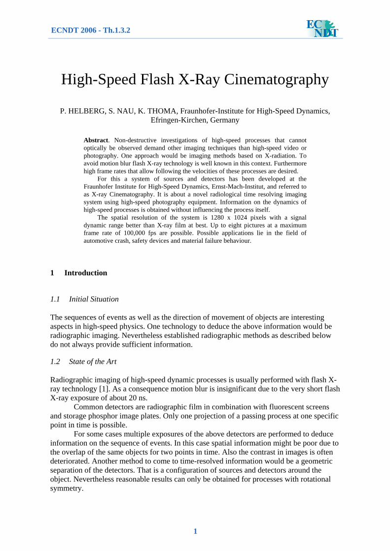
An approach for a detector system that is likewise proposed in [2, 3, 4] has been realized. A series of flash X-ray sources exposes a transient event. Fluorescent screens that decay fast enough take images of each specific point in time. The screens are simultaneously looked at with high-speed cameras.
2
High-Speed Cameraand / or array of cameras
(Mirror)
Fluorescent screen
Multi-Anode-Tube(Intensifier)
Figure 1. Cinematography Setup.
2.2 Time Resolution
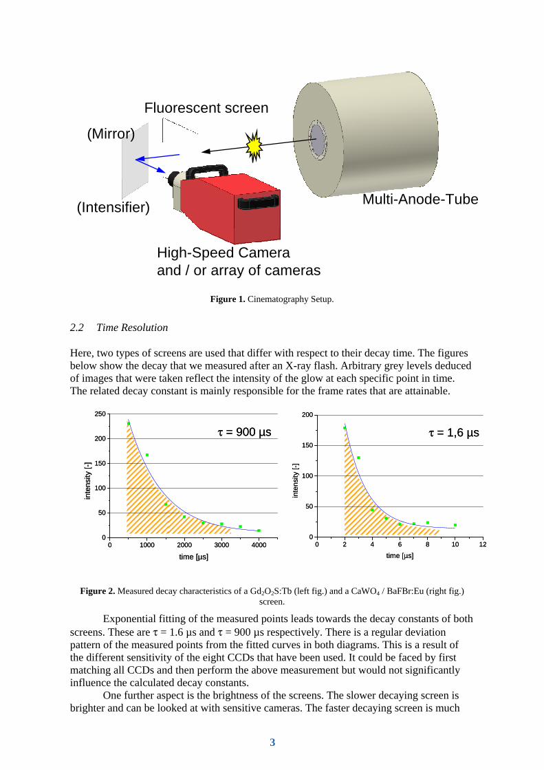
Here, two types of screens are used that differ with respect to their decay time. The figures below show the decay that we measured after an X-ray flash. Arbitrary grey levels deduced of images that were taken reflect the intensity of the glow at each specific point in time. The related decay constant is mainly responsible for the frame rates that are attainable.
0 1000 2000 3000 40000
50
100
150
200
250
inte
nsity
[-]
time [µs]
τ = 900 µs
0 1000 2000 3000 40000
50
100
150
200
250
inte
nsity
[-]
time [µs]
τ = 900 µs
0 2 4 6 8 10 120
50
100
150
200
inte
nsity
[-]
time [µs]
τ = 1,6 µs
0 2 4 6 8 10 120
50
100
150
200
inte
nsity
[-]
time [µs]
τ = 1,6 µs
Figure 2. Measured decay characteristics of a Gd2O2S:Tb (left fig.) and a CaWO4 / BaFBr:Eu (right fig.) screen.
Exponential fitting of the measured points leads towards the decay constants of both screens. These are τ = 1.6 µs and τ = 900 µs respectively. There is a regular deviation pattern of the measured points from the fitted curves in both diagrams. This is a result of the different sensitivity of the eight CCDs that have been used. It could be faced by first matching all CCDs and then perform the above measurement but would not significantly influence the calculated decay constants.
One further aspect is the brightness of the screens. The slower decaying screen is brighter and can be looked at with sensitive cameras. The faster decaying screen is much
3
darker. Electronic intensifying is needed. The screens are looked at simultaneously with one or more high-speed framing cameras. For the fast option we use an intensified camera with multiple ICCDs in it. The alternative we employ is an array of cameras each doing one picture only for the slower option.
For reasons that deal with the sensitivity of these cameras, external electronic intensifying is needed in the case of the fast decaying screen. Here we use a device with a second-generation intensifier that is based on a multi-channel-plate. The maximum multiplying factor of electrons therein is 100 000. The spectral sensitivity of the photo cathode for light reaches from 180 to 850 nm. The decay time of the output phosphor is less than 10 µs.
The whole system has to be carefully adjusted. Frame rates of 100 000 fps or 1000 fps with the above slowly decaying fluorescent screen are reached. Up to eight points in time are possible and have been realized.
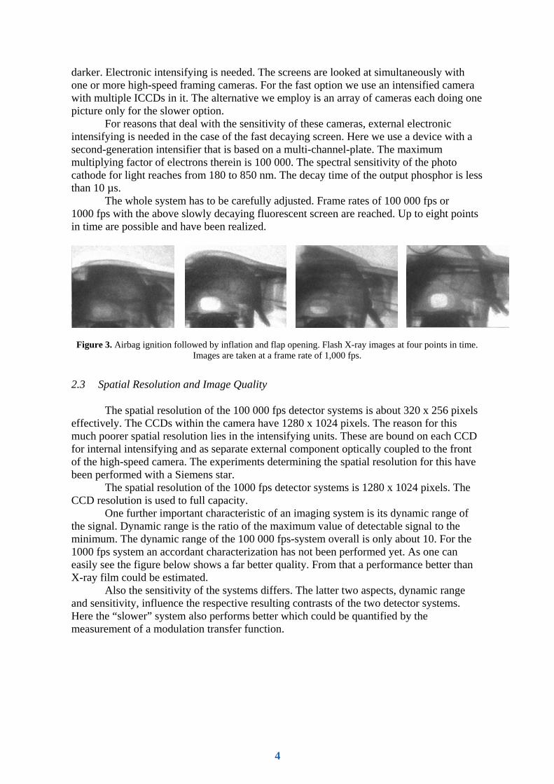
Figure 3. Airbag ignition followed by inflation and flap opening. Flash X-ray images at four points in time. Images are taken at a frame rate of 1,000 fps.
2.3 Spatial Resolution and Image Quality
The spatial resolution of the 100 000 fps detector systems is about 320 x 256 pixels effectively. The CCDs within the camera have 1280 x 1024 pixels. The reason for this much poorer spatial resolution lies in the intensifying units. These are bound on each CCD for internal intensifying and as separate external component optically coupled to the front of the high-speed camera. The experiments determining the spatial resolution for this have been performed with a Siemens star.
The spatial resolution of the 1000 fps detector systems is 1280 x 1024 pixels. The CCD resolution is used to full capacity.
One further important characteristic of an imaging system is its dynamic range of the signal. Dynamic range is the ratio of the maximum value of detectable signal to the minimum. The dynamic range of the 100 000 fps-system overall is only about 10. For the 1000 fps system an accordant characterization has not been performed yet. As one can easily see the figure below shows a far better quality. From that a performance better than X-ray film could be estimated.
Also the sensitivity of the systems differs. The latter two aspects, dynamic range and sensitivity, influence the respective resulting contrasts of the two detector systems. Here the “slower” system also performs better which could be quantified by the measurement of a modulation transfer function.
4
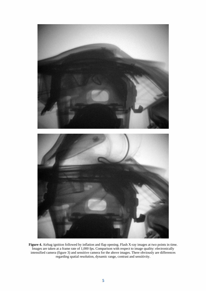
Figure 4. Airbag ignition followed by inflation and flap opening. Flash X-ray images at two points in time. Images are taken at a frame rate of 1,000 fps. Comparison with respect to image quality: electronically
intensified camera (figure 3) and sensitive camera for the above images. There obviously are differences regarding spatial resolution, dynamic range, contrast and sensitivity.
5

3 Summary
A new time-resolving flash X-ray measurement setup has been developed. This “Cinematography” setup has been tested with several high-speed applications in the field of automotive crash (e. g. the inflation of an airbag within the dashboard as presented), safety devices and material failure behaviour. The results show that this new method is performing well regarding applicability and deducible results. These are time-resolved radiographic images and therefore information on the kinematics of a dynamic process.
References
[1] L. E. Bryant. 1976. Proceedings of the Flash Radiography Symposium. 36th National Fall Conference, The American Society of Nondestructive Testing, September 28, 1976. [2] R. Hadland, B. A. Speyer : New cine X-ray systems. In: SPIE Vol. 491 High Speed Photography, Straßburg 1984. [3] J. P. Lucero, D. A. Fry, W. E. Gaskill, R. L. Henderson, T. R. Crawford, N. E. Carey : High Speed Cineradiography Using Electronic Imaging, SPIE Vol. 1801 High Speed Photography and Photonics (1992), Los Alamos National Laboratory, 1992. [4] V. V. Nagakar, S. V. Tipnis, V. Gaysinskiy, S. R. Miller, I. Shestakova : High-speed digital radiography using structured CsI screens, in: Nuclear Instruments and Methods in Physics Research B231 (2004) 476-480, 2004.
6