high security keyless access control - … smartguardair... · the factory default master code ......
TRANSCRIPT

SMARTGUARDair Operatinginstructions
TM
HIGH SECURITYKEYLESS ACCESS
CONTROL

How to use this Guide
General description
General use
Powering up
Glossary
KwikLearn
KwikPair
Technical specifications
Changing the Master Code
Adding a new user
Deleting a user
Deleting all users
Pairing
Setting the anti-hack parameters
Setting the Key Wipeout time
Setting the security parameters
Alarms
Backing up the unit
Restoring the unit
Defaulting the unit
Defaulting the Master Code
Defaulting the System Parameters
Battery low indication
Typical mounting instructions
Fitting the optional anti-tamper switch
External 12V DC power
Typical applications
Installation information
page 1
page 2
page 4
page 5
page 6
page 7
page 9
page 10
page 11
page 12
page 14
page 16
page 17
page 19
page 21
page 24
page 28
page 29
page 30
page 31
page 31
page 31
page 33
page 34
page 35
page 36
page 37
page 38
Contents

The procedures in this Guide require the user to perform
certain sequential actions on the SMARTGUARDair keypad.
To assist you, the combined state of the three LED indicators
on the keypad correspond with particular steps within a
procedure. When carrying out the procedures, please be
aware of the following:
The factory default Master Code ( is used
throughout this Guide as an example only. Refer to page 6
for instructions on how to change the Master Code.
Indicates a particular key to be pressed on the keypad
by the user
Indicates a lit LED
[ ] Indicates optional entries. If no variable is entered, the
system will use the default for the particular function,
where applicable
How to use this Guide
3 41 2
1
page 1

The CENTURION SMARTGUARDair is a durable, high quality
keypad designed to provide secure access control to
restricted areas. The weatherproof unit is wireless, and is
powered by two AA alkaline (penlight) batteries. When any
key is pressed, a backlight illuminates the keypad for ease of
use in low-light conditions.
Access is granted by the keying in of a valid access code.
The access code can vary from one to ten digits. Up to one
thousand different access codes can be stored within the
unit’s non-volatile memory.
Each access code is stored in a location of the memory,
referred to as an ‘address’.
New codes can be added and existing codes can be deleted
as required.
‘Token codes’ can be added, allowing only a preset number
of activations, after which the code automatically becomes
invalid.
Channel 3 is used as the Alarm Channel (refer to page 28)
and cannot be changed. If alarm functionality is required,
then it is advisable that Channel 3 is not assigned to any
other function.
Each code can activate one of fifteen channels built into the
SMARTGUARDair. A channel is very much the same as a
remote control button. Each channel can activate an external
CENTURION rolling code-compatible receiver, either stand-
alone, single channel, multichannel or integrated into
products such as the D5-Evo, D10, VECTOR2, etc.
General description
page 2

An Anti-hack feature can be enabled, causing the unit to
shut down after a pre-selected number of incorrect codes
have been entered. The unit will then reset after a pre-
selected time. A telltale LED will indicate that the Anti-hack
feature has been triggered.
Once programmed, the system can be backed up onto the
optional Backup Memory Module (Code PCA12201V1.0).
This allows the system to be easily restored if required.
An optional independent Anti-tamper Switch can be fitted
and wired internally to transmit an alarm signal if the unit
has been forced open, or removed from its mountings.
page 3

After a user has been added to the SMARTGUARDair’s
memory and the keypad has been paired with a compatible
rolling code receiver, access is granted by keying in a valid
code and confirming the entry with the # key.
For example, if the code is being used as
an access code, the user will enter the digits in sequence
and then press # . The green LED will illuminate briefly to
indicate that a valid access code has been entered. Briefly
pressing the # key after a code has been entered will
cause the SMARTGUARDair to transmit a signal for a
minimum of 750ms (milliseconds). However, holding down
the # key will allow for a transmission of up to eight
seconds which will accommodate receivers requiring longer
transmission times. (This may be referred to as Hash-Hold.)
General use
#
#
#
#
8 52 69
page 4

Powering up
In order to preserve battery life, the unit is packed
with the link fitted on the 12V side of the power
selection pins.
To select batteries as the primary power
source, bridge the pin marked ‘AA BATT’ with
the common (centre) pin.
For information on selecting 12V as the primary
power source, refer to page 36.
page 5

Glossary of terms
Access code
The code number the user will enter to gain access.
It can range in length from one to ten digits.
Address/User address
The location where the user’s code is stored in the keypad
memory. It can be any number between 1 and 999.
It should be recorded, allowing the user code to be
removed from the memory later if necessary.
Master Code
The code number required for programming the keypad.
It is stored in user address 0.
The default Master Code of a new unit
is .
For security reasons, the installer should
change this code at the time of installation.
Although 1234 is the default Master Code, up
to ten digits per code may be specified, and is
encouraged to improve security.
Refer to page 11 for instructions on how to change
the Master Code.
3 41 2
Enter key
In order to gain access, the user code must be followed by
the key. (Refer to General use section on page 4.)
#
#
page 6

Add a new access code at a specified address.
The code will operate Channel 1 only.
The following KwikLearn procedure and connection diagrams (see pages 35 and 36) will enable you to start using your SMARTGUARDair system right away.
KwikLearn
The SMARTGUARDair will have to be paired to a
valid receiver before a code will be able to activate it.
Thus, the KwikLearn procedure will store a new code
in the keypad’s memory, but the code will still have
to be associated with a receiver using either the
KwikPair facility described on page 9, or the Pairing
procedure on page 17.
11. Enter Program Mode Master Code
2. Select KwikLearn
3. Enter user address
4. Enter access code new access code1 Default Master Code=1234
Indicator LEDs
Enter the following keystrokes:
0
0
STANDBY
page 7

Example:
KwikLearn access code into address
Master Code=
2 5
9 3 42 5
1. Enter Program Mode
2. Select KwikLearn
3. Enter user address
4. Enter access code
Enter the following keystrokes:
Indicator LEDs
0
3
3
2
4
4
4 5
1
1
9
2
2
3 2 5
page 8
STANDBY

The SMARTGUARDair must now be paired with a
CENTURION rolling code radio receiver.
1. Place the receiver into Learn Mode.
2. Enter a valid access code on the SMARTGUARDair,
followed by .
The SMARTGUARDair will now transmit for a short
time, and will pair with the receiver.
Hash-Hold may be used (as described on page 4) to
extend the transmission time to suit the learning
procedure associated with certain types of receivers.
3. Exit Learn Mode on the receiver
4. Test the system by entering a valid access code,
followed by .
KwikPair
page 9

Battery supply voltage
External power supply
Wireless range
Operating temperature
Operating humidity
Output
Housing material
Degree of protection
Battery life
Code length
Memory capacity
Memory retention
Token codes
Only replace with Alkaline batteries. Other types of batteries (NiMH,
Li-Ion, etc. ) as well as rechargeable batteries cannot be used with
this product.
Specified as Line of Sight (LOS) range
Non-condensing
Subject to usage - refer to table in the Battery Low Indication
Section on page 33
2 x AA Alkaline batteries
(voltage range: 2.6V - 3.3V)
External 12V DC power supply
30 metres
-18°C to +55°C
0 - 90%
14 standard channels + one alarm
channel
Polycarbonate
IP55
Two to five years
One to ten digits
1000 unique codes (non-volatile )
>200 years
1 - 254 activations
Technical specifications
page 10

1. Enter Program Mode
2. Select KwikLearn
3. Enter address
4. Enter access code
The following procedure will enable the user to change the
default Master Code or the currently stored
Master Code to a new Master Code. The Master Code may
also be learned into the system by following the procedure
on page 12, ‘Adding a New User’.
Enter the following keystrokes:
Indicator LEDs
Example: Replace the default Master Code with
a new Master Code = 3\
0
0
3 7 8 1
3 4
Changing the Master Code
The Master Code must always be stored at address
The Master Code can be used as a normal access code and can be up to ten digits long
11. Enter Program Mode Master Code
2. Select KwikLearn
3. Enter address
4. Enter new code Master Code1Default Master Code=
Indicator LEDs
Enter the following keystrokes:
0
0
0
1 2
3 41 2
3 41 2
3 41 2
8 13 7
page 11
STANDBY
STANDBY

STANDBY
1. Enter Program Mode Master Code
2. Select Add Menu
3. Enter user address Address
4. Enter access code new access code
5. Select channel Channel
6. Enter access limit [Accesses]
7. Exit Add Menu
8. Exit Program Mode
The following procedure will add a new access code at a
specified location in the SMARTGUARDair’s memory,
referred to as an ‘address’ and will assign which channel the
code must activate and how many accesses are allowed
before the code becomes invalid.
Indicator LEDs
Enter the following keystrokes:
1
Adding a new user
Repeat steps 3 - 6 for additional users [ ] denotes optional variable
If unlimited accesses are required, only enter
# at Step 6. If no channel is specified, Channel 1 is selected by
default If the number of accesses is not specified in Step 6,
unlimited access is set. Care must be taken to
ensure the desired access limit is correctly applied
page 12
1. Enter Program Mode
2. Select Add Menu
3. Enter user address
4. Enter access code
5. Select channel
6. Enter access limit
7. Exit Add Menu
8. Exit Program Mode
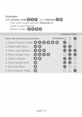
Example:
Add access code into address
The code mxust operate Channel 2
Code is valid forever
Master Code=
Indicator LEDs
Enter the following keystrokes:
1
1
1 32
0
4
5 72
2
75 12 0
3 41 2
page 13
STANDBY

1. Enter Program Mode Master Code
2. Select Delete Menu
3. Enter user address Address
4. Exit Delete Menu
5. Exit Program Mode
The following procedure will delete an access code at a
specified address.
Indicator LEDs
Enter the following keystrokes:
2
Deleting a user
1. Enter Program Mode
2. Select Delete Menu
3. Enter user address
4. Exit Delete Menu
5. Exit Program Mode
Indicator LEDs
Enter the following keystrokes:
2
9
1 32
9
4
Example:
Delete access code at address .
Master Code= 3
9
4
9
1 2
page 14
STANDBY
STANDBY

Example:
Delete access codes at multiple addresses, such as
and .
Master Code= 3
8
4
7
1
5
2
4
page 15
1. Enter Program Mode
2. Select Delete Menu
3. Enter user address
4. Enter user address
5. Exit Delete Menu
6. Exit Program Mode
Indicator LEDs
Enter the following keystrokes:
2
5
8
4
7
1 32 4
STANDBY

It is possible to delete all users stored in the
SMARTGUARDair’s memory, by entering as the user
address. This will cause the Master Code to be reverted back
to and erase all user codes programmed into
the memory.
Delete all users
0
3 41 2
1. Enter Program Mode Master Code
2. Select Delete Menu
3. Enter user address
4. Exit Delete Menu
5. Exit Program Mode
Indicator LEDs
Enter the following keystrokes:
2
0
STANDBY
page 16
1. Enter Program Mode
2. Select Delete Menu
3. Enter user address
4. Exit Delete Menu
5. Exit Program Mode
Example:
Delete all access codes. Master Code=
Indicator LEDs
Enter the following keystrokes:
2
0
1 32 4
3 41 2
STANDBY

A clear distinction must be made between the Pairing Menu
and the Adding Menu (refer to page 12).
The Adding Menu will be used whenever a new code is to be
added to the SMARTGUARDair’s memory. This will in turn
create a means of ‘unlocking’ transmission to a designated
receiver; whereby a valid code will have to be entered before
the unit will begin transmitting.
The Pairing Menu allows the user to pair the
SMARTGUARDair to one or more CENTURION rolling code
receivers within the specified range of transmission;
comparable to learning a remote control into a receiver.
Once transmission has ended, repeat Steps 3 and 4 for
additional channels.
Pairing
1. Enter Program Mode Master Code
2. Select Pairing Menu
3. Enter channel Channel
4. Enter receiver type* [ OR ]
5. Enter transmission time [0 - 90 seconds]
6. Exit Pairing Menu
7. Exit Program Mode
* for NOVA receiver
for future CENTURION receiver
Indicator LEDs
Enter the following keystrokes:
3
0
0
1
1
page 17
STANDBY

The default transmission duration is eight seconds,
and will be automatically selected if no other value
is specified The maximum transmission time is 90 seconds If no receiver is specified, NOVA is selected by
default Additional functionality, such as pulsing or latching
outputs is handled by the associated receiver
Example:
Pair Channel 1 with a NOVA receiver, allowing for a
transmission duration of ten seconds.
Master Code=
1. Enter Program Mode
2. Select Pairing Menu
3. Enter channel
4. Enter receiver type
5. Enter transmission time
6. Exit Pairing Menu
7. Exit Program Mode
Indicator LEDs
Enter the following keystrokes:
3
0
1 0
1
1 32 4
3 41 2
page 18
STANDBY

1. Enter Program Mode Master Code
2. Select Lockout Menu
3. Enter number of codes Wrong codes
4. Enter Reset Time Seconds
5. Exit Program Mode
The following procedure sets the number of consecutive
wrong access codes that the SMARTGUARDair will accept
before becoming inactive, as well as the time for which it will
remain inactive.
The Factory Default for wrong access codes is three, while the
default reset time is 60 seconds.
Indicator LEDs
Enter the following keystrokes:
4
Setting the anti-hack parameters
page 19
STANDBY
The unit will revert to normal operation after the
specified Reset Time
The orange LED will flash briefly every four
seconds as a telltale that the anti-hack alarm has
been invoked
The telltale LED indication will revert to the
normal red LED flashing indicator on correct entry
of a code

1. Enter Program Mode
2. Select Lockout Menu
3. Enter number of codes
4. Enter Reset Time
5. Exit Program Mode
Indicator LEDs
Enter the following keystrokes:
4
5
3 0
Example:
Set Wrong Code Alarm to activate after five incorrect
codes have been entered. The unit must revert to normal
operation after 30 seconds.
Master Code=
1 32 4
3 41 2
page 20
STANDBY

Setting the Key Wipeout time
page 21
The following procedure sets the number of seconds for which
keystrokes remain valid. This ensures that if a partial code
has been entered, it is wiped out of the keypad buffer after a
preset time, and must be re-entered in its entirety. The Key
Wipeout time may be specified from 0 to 255 seconds.
The value is interpreted as follows:
0 - Key Wipeout is disabled
1- 255 - Key Wipeout occurs after the specified number
of seconds. The keypad backlight generally mirrors the
Key Wipeout setting.
The following rules apply to the Key Wipeout time and the backlight time:
If the device is battery powered:
The Key Wipeout time never exceeds 15 seconds; irrespective of the time the user has set as the Key Wipeout time
The backlight mirrors the Key Wipeout time exactly
If the device is externally powered:
The Key Wipeout time is not restricted in any way The backlight remains on indefinitely; irrespective of
the Key Wipeout time setting

1. Enter Program Mode Master Code
2. Select Key Wipeout Menu
3. Enter Key Wipeout Time [Seconds]
4. Exit Program Mode
Indicator LEDs
Enter the following keystrokes:
5
STANDBY
If the Key Wipeout time is set to , Key Wipeout
will be disabled (only applicable to externally-
powered devices)
0
Disabling the Key Wipeout time will: Compromise the security of the system Cause a code entry to be incorrectly recognised as
a wrong code if an incomplete code was previously
entered
page 22

Example:
Disable Key Wipeout time.
Master Code=
1. Enter Program Mode
2. Select Key Wipeout Menu
3. Enter Key Wipeout Time
4. Exit Program Mode
Indicator LEDs
Enter the following keystrokes:
5
0
1 32 4
3 41 2
page 23
Example:
Set the Key Wipeout time to 15 seconds.
Master Code=
1. Enter Program Mode
2. Select Key Wipeout Menu
3. Enter Key Wipeout Time
4. Exit Program Mode
Indicator LEDs
Enter the following keystrokes:
5
1 5
1 32 4
3 41 2
STANDBY
STANDBY

The following procedure sets the conditions under which the
Alarm channel (Channel 3) will activate. This also sets the
Anti-default and Keypad Alarm Tone Mute features.
The following alarm conditions can be set:
Duress (Code + one)(Default=off)
Adding one to the last digit of an access code activates
the unit as normal, but also activates the alarm channel.
This is used if entering under duress.
E.g. If the access code is , entering
gives access, but also activates the alarm.
Setting the security parameters
3 51
#
#
3 41 2
2
page 24
Panic Alarm ( + )(Default=off)
Pressing the and keys simultaneously activates
the Alarm channel.
Wrong Codes (Default=off)
When the number of wrong codes is exceeded, the Alarm
channel is activated.
Anti-default feature (Default=on)
To achieve greater security, this feature prevents the
system parameters from being reset by the defaulting
features.
Important when choosing an access code
number
If you intend using the Duress Security
Parameter, ensure that no consecutive numbers
are assigned as access codes.
Ensure that the desired code has not already
been allocated

1. Enter Program Mode Master Code
2. Select Security Menu
3. Set Duress (Code+1) OR
4. Set Panic Alarm (*+#) OR
5. Set (Wrong Codes) OR
6. Set Anti-default OR
7. Set Alarm Tone Mute OR
8. Exit Program Mode
Indicator LEDs
Enter the following keystrokes:
6
0
0
0
0
0
1
1
1
1
1
0 turns function off, turns function on1
STANDBY
The Master Code can still be defaulted to ,
but doing this will break the pairing between the
SMARTGUARDair and any paired receivers.
This pairing will need to be re-established in order to
continue using the system.
Keypad Alarm Tone Mute feature (Default=off)
Establishing this feature turns off the audible feedback
when entering a code. This prevents an eavesdropper
from determining the number of digits in the code.
Tones will still be present in Programming Mode.
page 25
3 41 2

page 26
Example:
Enable Duress Alarm on (Code + one). Clear all other
Alarm functions.
Master Code=
1. Enter Program Mode
2. Select Security Menu
3. Set Duress (Code+1)
4. Clear Panic Alarm (*+#)
5. Clear (Wrong Codes)
6. Clear Anti-default
7. Clear Alarm Tone Mute
8. Exit Program Mode
Indicator LEDs
Enter the following keystrokes:
6
0
0
0
0
1
1 32 4
3 41 2
STANDBY

Example:
Set Alarm on Wrong Codes and leave all other
functions unchanged.
Master Code=
1. Enter Program Mode
2. Select Security Menu
3. Skip Duress (Code+1)
4. Skip Panic Alarm (*+#)
5. Set (Wrong Codes)
6. Skip Anti-default
7. Set Tone Mute
8. Exit Program Mode
Indicator LEDs
Enter the following keystrokes:
6
1
1 32 4
3 41 2
page 27

The SMARTGUARDair allows four different alarms to be set,
each of which will activate Channel 3, the designated Alarm
Output Channel.
The four alarms available on the SMARTGUARDair are as
follows:
Duress Alarm - a settable alarm feature, activated by
adding one to the last digit of an access code
Panic Alarm - a settable alarm feature, activated by
pressing the and keys simultaneously
Multiple Wrong Codes Alarm - a settable alarm
feature; it is activated by exceeding the pre-set number
of allowable wrong codes
Anti-tamper Alarm - a non-settable alarm feature,
activated when the anti-tamper input is activated.
This alarm is always enabled and it is therefore
recommended that Channel 3 be used exclusively as an
Alarm Output Channel to ensure greater security
Alarms
#
page 28

It is possible to back up all the user access codes as well as
the system settings to the optional Backup Memory Module
(PCA12201v1.0).
This allows the system to be easily restored in the unlikely
event of system failure.
Procedure for backing up the unit:
Remove power. Plug the Backup Memory Module into the
socket provided. Reapply power. All three LEDs will now
be ON.
Enter Master Code , then press on the keypad.
The green LED will begin to flash, indicating that the
memory is being backed up. When the backup is
complete, a beep will be heard, and the green LED will
turn off. Remove the Backup Memory Module and keep it
in a safe place.
Backing up the unit
1
Backing up to a Backup Memory Module will
overwrite any information that was previously
contained in that Backup Memory Module
page 29

Restoring from a Backup Memory Module will
overwrite any information that was previously
contained in the SMARTGUARDair unit
Restores all the user access codes as well as system
settings from the optional Backup Memory Module
(PCA12201v1.0).
Procedure for restoring the unit:
Remove power. Plug the Battery Backup Module into the
socket provided. Reapply power. All three LEDs will now
be ON.
Enter Master Code , then press on the
keypad. The yellow LED will begin to flash, indicating
that the memory is being restored. When the memory
has been restored, a beep will be heard, and the yellow
LED will turn off.
Remove the Backup Memory Module and keep it in a
safe place.
Restoring the unit
3
page 30

Defaulting the unit
1
3 41 2
Both the Master Code and the system parameters (timers,
alarm functions, etc.) can be reset to Factory Defaults.
This is useful when the Master Code has been forgotten or
the system parameters are in an unknown state.
Defaulting the Master Code:
Remove power. Reapply power while holding the key
down for two seconds. A beep will then follow, indicating
that the Master Code has been reset to .
If the Anti-default feature has been enabled, the pairing
between the receiver will be broken during this process.
page 31
If the user identifies that the pairing has been
broken, it is the user's responsibility to ensure
that the keypad has not been tampered with, i.e.
that additional codes have not been learned into
the system. It is advisable, upon realising that
the pairing has been broken, to completely
default the keypad and erase the codes memory,
or to restore the memory using a Backup
Memory Module.
The pairing will have to be re-established before the
system becomes functional.
Defaulting the System Parameters:
Remove power. Reapply power while holding the and
keys down together for two seconds. A beep will then
follow, indicating that the System Parameters have been
reset to the Factory Defaults shown on the following
page.
2
3

Defaulting is not possible if the Anti-default feature
has been set (see page 24) .
In this case, if the Master Code has been lost, the
Master Code must be defaulted back to ,
which will break the pairing between the
SMARTGUARDair and all paired receivers.
This pairing will need to be re-established in order to
continue using the system.
3 41 2
page 32
Wrong Codes: Three codes
Wrong Codes Reset: 60 seconds
Key Wipeout timer: Five seconds
Security Parameters: Anti-default ON, all others OFF
By default, the anti-default parameter is enabled to ensure maximum security of the unit.

1. Remove retaining
screw cover and
screws.
2. Insert screwdriver
blade into groove
provided between the
cover and back panel.
Lever screwdriver
forward to separate
the cover from the
back panel.
Typical mounting instructions:
page 34
3. Fix the self-adhesive
rubber pads into the
recesses provided on
the rear panel.
4. Attach the rear pane to
the mounting
surface/gooseneck with
the mounting screws
supplied.
Be sure to seal all
the mountings with
silicone sealant.
Use only the mounting holes shown. If the other
mounting holes are used, the mounting screws will
interfere with the batteries.
2
1
Retaining screw cover
3
4
Self-adhesiverubber pads
Mounting screws

Battery low indication
Once the batteries start to near the end of their service life,
the SMARTGUARDair will detect the battery low condition
and both visible and audible indications will be provided.
The following indications should be noted by the user:
Visible: The red LED will flash rapidly three times, and
repeat this action every four seconds
Audible: The tone of the onboard buzzer will be
different from its normal pitch during key presses
There will still be a fair amount of usage left before the
batteries are completely drained, but it is advisable to
replace them as soon as possible to ensure continued
operation.
page 33
Daily operations Battery life
One 12 years
Ten 10 years
50 5 years
100 3 years
200 2 years
500 1 year
The battery life is characterised but not necessarily
tested.

Anti-tamper Switch
The Anti-tamper Switch input is a normally-open input. In other words, the input must be tied to common to trigger the Anti-tamper Alarm.
If the onboard terminals are used to connect the anti-tamper switch, the switch’s normally-closed (N/C) and common connections MUST be used. Normally-closed (N/C) will be connected to In1 and COM to Neg (-)
If the anti-tamper switch is to be connected to a third-party alarm system, either normally-closed or normally-open can be used, along with a common connection
In1
12
3
To third partyalarm system
Onboard alarm option - activates Alarm Channel (Channel 3)
page 35

External 12V DC power
page 36
Refer to this diagram only if an external 12V power source
is to be used. Even though an external power supply will
provide a more or less unlimited duty cycle, there will be
no autonomy whatsoever in the event of a power failure.
Should an external 12V power supply be used,
the power selection link must be moved to
bridge the pin marked ‘12 Volt’ with the
common (centre) pin.
The supply voltage should not exceed 12V DC
From external12V DC power supply
In1

Typical applications
page 37
Channel 7
Garage door operator
Gate operator
Alarm
Channel 3
Channel 1
ghi jkl mno
pqrs tuv wxyz
abc def
3

IMPORTANT installation information
Complete the installation information below for future
reference.
Master Code
Channel 1 activates
Channel 2 activates
Channel 3 (Alarm Channel) activates
Channel 4 activates
Channel 5 activates
Channel 6 activates
Channel 7 activates
Channel 8 activates
Channel 9 activates
Channel 10 activates
Channel 11 activates
Channel 12 activates
Channel 13 activates
Channel 14 activates
Channel 15 activates
page 38
Keep this manual in a safe place.
Channel 3 is always the Alarm Channel, if any of the alarms are used (activated).

For your convenience you will find an Address Register
included in your SMARTGUARDair packaging. Use this
Address Register to record which addresses have been
assigned, their access code and which channel will be
activated by that address.
The supplied Address Register will record the first 512
addresses, from 0 to 512, as well as a space to record your
new Master Code. Should you require a second Address
Register to record the next 487 addresses, please contact
your nearest CENTURION SYSTEMS branch or distributor.
Installers information:
Name:
Mobile number:
Email address:
Physical address:
Keep the address register in a safe place!
page 39

www.centsys.com
0.07.A.0109_22072013
Sharecall 0860-CENTURION (0860 236 887)Head Office: +27 11 699 2400
Sharecall Technical Support 0861 003 123 or +27 11 699 2481from 07h00 to 18h00 (GMT+2)
(Sharecall numbers applicable when dialed from within South Africa only)