high res electron de broglie wavelength 12.3 v
TRANSCRIPT
10/21/2015
1
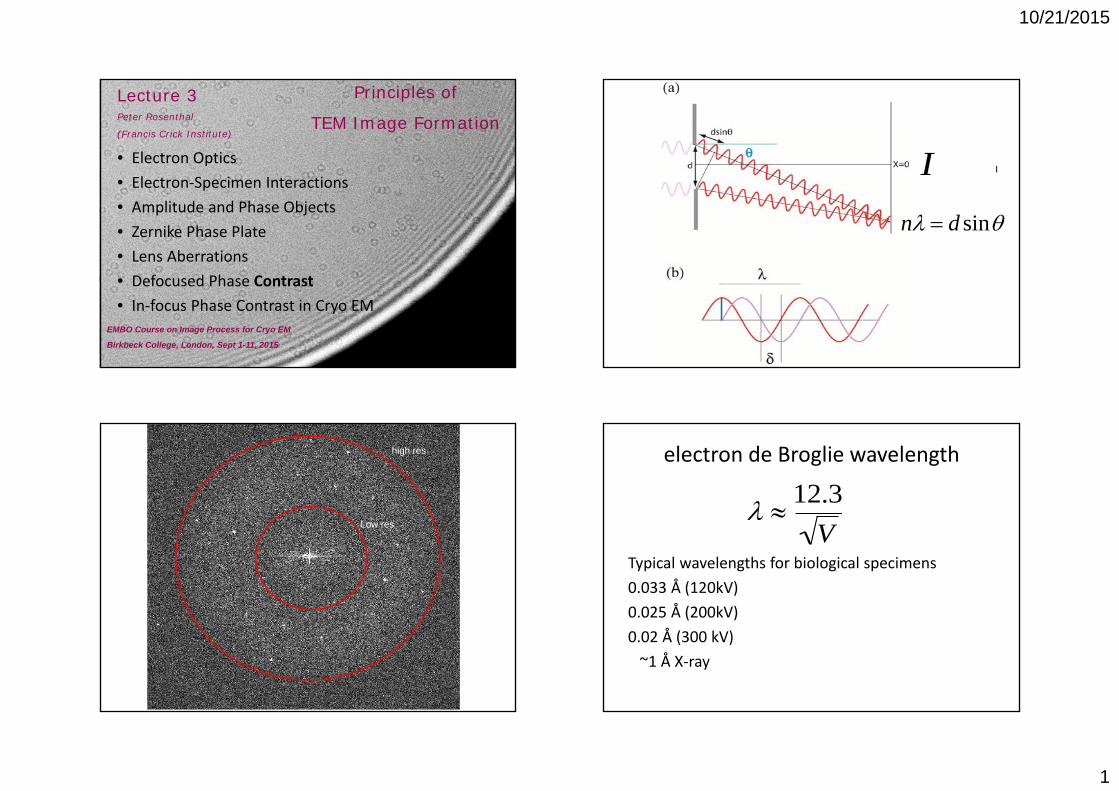
Principles of
TEM Image FormationLecture 3Peter Rosenthal
(Francis Crick Institute)
EMBO Course on Image Process for Cryo EM
Birkbeck College, London, Sept 1-11, 2015
• Electron Optics• Electron‐Specimen Interactions• Amplitude and Phase Objects• Zernike Phase Plate• Lens Aberrations• Defocused Phase Contrast• In‐focus Phase Contrast in Cryo EM
n d sin
II
Low res
high res electron de Broglie wavelength
Typical wavelengths for biological specimens0.033 Å (120kV)0.025 Å (200kV)0.02 Å (300 kV)~1 Å X‐ray
12.3
V
10/21/2015
2
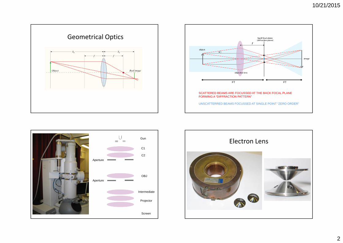
Geometrical Optics
SCATTERED BEAMS ARE FOCUSSED AT THE BACK FOCAL PLANEFORMING A “DIFFRACTION PATTERN”
UNSCATTERRED BEAMS FOCUSSED AT SINGLE POINT “ZERO ORDER”
FT FT
Gun
C1
C2
OBJ
Intermediate
Projector
Screen
Aperture
Aperture
Electron Lens

10/21/2015
3
Electron‐specimen interaction
• Coulomb field: positive nucleus, negative cloud• Depends on atomic properties (Z)• Elastic Scattering• Inelastic Scattering• Atomic scattering factors
Published in: E. V. Orlova; H. R. Saibil; Chem. Rev. Article ASAPCopyright © 2011 American Chemical Society
Amplitude Object
Phase Object
Amplitude Object
Phase Object

10/21/2015
4
PHASE SHIFT
ie
Phase Object Approximation: electrons experience a phase shift on passing through the projected 2D Coulomb potential of the specimen
i ( x ,y )e
(x, y) (x, y,z)dz
Weak Phase Object Approximation
The transmitted wave is the resultant of the unscattered wave and the second term is the scattered wave with a 90 phase shift.
ei ( x ,y ) 1 i x, y ... The phase shift is very small, in which case:
Thin biological specimens are weak phase objects
• Proteins Low Z atoms (C,O,P,N) 1.35 g/cm3
• Vitreous Ice 0.92 g/cm3
21i x,y 1 2 1 No Contrast!We measure intensities at the image plane:

10/21/2015
5
Zernike Phase Plate
Zernike, F. How I discovered phase contrast. Science 121, 345‐9 (1955).
4
Phase Contrast
Amplitude Contrast
Zernike Phase Contrast
• The phase plate changes the relative length of the optical path of the diffracted beams with respect to the zero‐order beam (such that an extra phase
• Converts phase contrast to amplitude contrast.• Possible because of separation of unscattered and scattered waves at the back focal plane.
Contrast in TEM
Negative Stain
Cryomicroscopy
Cryo-Negative Stain

10/21/2015
6
Scattering/Aperture Contrast
Negative Stain
Lens Aberrations
Source: Wikipedia
Ray diagrams of lens aberrations: (a) perfect lens, (b) spherical, (c) chromatic, and (d) astigmatic aberration. F is the focal length of the lens.
Published in: E. V. Orlova; H. R. Saibil; Chem. Rev. Article ASAPCopyright © 2011 American Chemical Society
Path Length Difference/Phase Shift Due to Lens Aberrations
Cs4 Spherical Aberration
=0 is not affected!

10/21/2015
7
Scattererat focus
Scatterernot at focus
Defocus Phase Contrast
F 2Defocus
=0 is not affected!
Path Length Difference/Phase Shift Due to Lens Aberrations
Cs4
Spherical Aberration
X
Defocus
Phase contrast for selected
• The contrast of a spacing X of the image is modified by thephase contrast transfer function: 2sin (X)
Erickson, H. P. The Fourier Transform of an Electron Micrograph‐First Order and Second Order Theory of Image Formation. Advances in Optical and Electron Microscopy 5 (1973).
Erickson, H. P. & Klug, A. Fourier Transform of an Electron Micrograph ‐ Effects of Defocussing and Aberrations, and Implications for Use of Underfocus Contrast Enhancement. Berichte Der Bunsen‐Gesellschaft Fur Physikalische Chemie 74, 1129‐& (1970).
X
Phase contrast for selected

10/21/2015
8
Contrast Transfer Function
FFT of Carbon Film
F1F2Angle of astigmatism
F F1cos2 F2 sin2
Scherzer Focus
Defocus choice for proteins Weak Phase/Weak Amplitude Objects
eu(x,y) 1u(x, y)
1 i(x, y) 1u(x, y)
2sin (X)Q2cos (X)Contrast TransferFunction
ei (x,y)eu(x,y) 1 i x, y ... eu(x,y)
IF WE LOOK AT THE EFFECT ON THE IMAGE:
Weak Phase
Weak Amplitude

10/21/2015
9
The fraction (Q) of amplitude contrast for proteins in ice has been measured:
5.8% at 120kV4.8% at 200kV2.7% at 300kV, (6.9% when using an energy filter).
Toyoshima, C. & Unwin, N. Ultramicroscopy 25, 279-91 (1988).Toyoshima, C., Yonekura, K. & Sasabe, H. Ultramicroscopy 48, 165-176 (1993).Yonekura, K., Braunfeld, M. B., Maki-Yonekura, S. & Agard, D. A. J Struct Biol 156, 524-36 (2006).
2sin(X)Q2cos(X)Contrast Transfer Function
FFT of Carbon Film
F1F2Angle of astigmatism
2
(F 2
2
Cs 4
4)
F F1cos2 F2 sin2
In‐focus Phase Contrast Electrons
Boersch, S. Z. Naturforsch. 2a, 615 (1947).Unwin, P. N. Phase contrast and interference microscopy with the electron microscope. Philos Trans R Soc Lond B Biol Sci
261, 95‐104 (1971).Majorovits, E. et al. Optimizing phase contrast in transmission electron microscopy with an electrostatic (Boersch) phase
plate. Ultramicroscopy 107, 213‐26 (2007).Cambie, R., Downing, K. H., Typke, D., Glaeser, R. M. & Jin, J. Design of a microfabricated, two‐electrode phase‐contrast
element suitable for electron microscopy. Ultramicroscopy 107, 329‐39 (2007).Danev, R. & Nagayama, K. Transmission electron microscopy with Zernike phase plate. Ultramicroscopy 88, 243‐52
(2001).
Danev, R. & Nagayama, K. Single particle analysis based on Zernike phase contrast transmission electron microscopy. J Struct Biol 161, 211-8 (2008).

10/21/2015
10
Recommended Books1. Reimer, L. Transmission electron microscopy : physics of image formation and microanalysis
(Springer, Berlin ; New York, 1997).2. Frank, J. Three‐dimensional electron microscopy of macromolecular assemblies :
visualization of biological molecules in their native state (Oxford University Press, Oxford ; New York, 2006).
3. Slayter, E. M. & Slayter, H. S. Light and electron microscopy (Cambridge University Press, Cambridge [England] ; New York, 1992).
4. Misell, D. L. Image Analysis, Enhancement and Interpretation (ed. Glauert, A. M.) (Elsevier Science & Technology, Oxford, 1978).
5. Spence, J. C. H. High‐resolution electron microscopy (Oxford University Press, Oxford ; New York, 2003).
6. Glaeser, R. M. Electron crystallography of biological macromolecules (Oxford University Press, Oxford ; New York, 2007).
7. Cowley, J. M. Diffraction physics (North‐Holland ; Sole distributor for the U.S.A. and Canada Elsevier Science Pub. Co., Amsterdam ; New York, 1984).
8. Hawkes, P. W. & Valdrè, U. Biophysical electron microscopy : basic concepts and modern techniques (Academic Press, London ; San Diego, 1990).