high-pressure test facility - 25 years of operation* · high-pressure test facility - 25 years of...
TRANSCRIPT

High-Pressure Test Facility -25 Years of Operation*
H. Schmidt, W. Köhler, W. Kastner
Framatome ANP GmbH(A Framatome and Siemens Company)Erlangen, GermanyMarch 2001
* Extended version of the publication with the same title in VGB Power Tech, 06/2000, pp. 25-31
Tel.: +49 (0) 9131 18 93718Fax.: +49 (0) 9131 18 92851E-mail: [email protected]

- -
25JahreBENSONbild_E.doc
2
High-Pressure Test Facility – 25 Years of OperationW. Kastner, W. Köhler, H. Schmidt
IntroductionA high-pressure test facility which is installed in an accred-ited laboratory at Framatome ANP in Erlangen, Germanyand is unique throughout the world due to its wide range ofoperating conditions – called the BENSON test rig – is nowcelebrating its 25th anniversary. This is an exceptional eventfor any test facility and marks a good occasion for taking alook at the tests and research work that have been per-formed at the test rig in order to demonstrate its broadrange of applications. The results of this work have fre-quently served as a basis for developing design tools aswell as for finding solutions to issues related to power plantoperation. As the name of the test rig implies, its main pur-pose is to investigate topics associated with the operationand further development of BENSON boilers. In addition tothis, the test facility is also used for issues related to powergeneration using nuclear and renewable energy sources.However, before details are given of examples of past proj-ects, a brief description of the test rig will first be presentedbelow.
A High-Pressure Test Facility – The BENSON Test RigIn its role as a licensor for BENSON boilers, Siemens PowerGeneration responded in 1973/74 to the need for supple-mentary research and development work in this field bymaking the foresighted decision to set up a new test facilitywith wide-ranging capabilities. The BENSON test rig – inoperation since 1975 – has been used for investigatingnumerous topics and has been continually adapted to newdevelopments in science and technology. Its range of oper-ating conditions is based on the service requirements ofBENSON boilers and raw-gas heat-recovery steam gen-erators. The test rig's design data are:
− System pressure 330 bar− Temperature 600 °C− Mass flow 28 kg/s− Heating capacity 2000 kW.
The test facility mainly comprises – see Figure 1 – a watersupply system, the object to be tested, a pressurizer and acooling system. In the water supply system, demineralizedand deaerated water or boiler feedwater to which chemicalshave been added to obtain the required water chemistry isprovided in a feedwater tank. This water is injected into thetest loop by a piston pump. To minimize flow oscillationscaused by the pump's six pistons, a damping vessel is in-stalled in the pump discharge line.
Fig. 1: Flow diagram of BENSON test rig
The water is heated in a main heater to establish the ther-modynamic flow conditions required at the inlet to the testobject. This coil-type heater is designed for direct electricheating; i.e. an electric current flows through the wall of thecoil which acts as a resistor and is thereby heated. Theadvantage of this heating method is that it allows precisecontrol of the heat added to the fluid. This is particularlyimportant in connection with the development of heattransfer and pressure drop correlations. Experiments usingother methods such as radiation heating (performed per-haps directly in a power plant) are less suitable for suchtasks since precise determination of fluid enthalpy or ofactual heat input is more difficult.
After the fluid has passed through the main heater it entersthe test section, which is likewise equipped for direct electricheating. Here the flow and heat transfer conditions aresimulated and monitored. Depending on the task in hand,the test object can consist of various kinds of tubes andvessels. Further details will be provided when the applica-tions for which the test rig has been employed are describedbelow.
Installed downstream of the test object is a spray-type con-denser for condensing the steam fraction and subcoolingthe fluid. The subcooled fluid then passes to a circulationpump which recirculates part of the flow for cooling thespray condenser. Condenser cooling water is taken from themain flow immediately downstream of the pump as well asfrom the main cooler which is supplied on its secondary sidewith water from a wet cooling tower (trickle cooler).

- 3 -
25JahreBENSONbild_E.doc
System pressure is adjusted by a large thermal pressurizerand a throttling valve (pressure-reducing valve) downstreamof the test object. Assurance of a constant pressure is par-ticularly important for investigations performed near thecritical pressure since pressure fluctuations can affect heattransfer conditions in the test object.
If the mass flow exiting the test loop is smaller than thatsupplied by the piston pump, the level of water inside thepressurizer initially rises. This does not, however, lead toany increase in system pressure since the steam cushionprovided inside the pressurizer is compressible. The rise inwater level is, however, used as a process control variableto open the pressure-reducing valve at the end of the testloop.
If large mass flows are required for certain investigations,the test rig can be operated in the recirculation mode. In thiscase the water is not injected into the test loop by the pistonpump, as when the test rig is operating in the once-throughmode, but is recirculated by the circulation pump instead.
The entire test facility is made of austenitic stainless steeland is thermally insulated by means of an approximately50-mm-thick layer of rockwool. Figure 2 provides a view ofpart of the test facility and some of its major components.
Fig. 2: View of BENSON test rig
The BENSON test rig as well as the test object are instru-mented in such a way that all relevant parameters such astemperature, pressure and flow can be measured.
Data acquisition and process visualization play a key rolefor recording and monitoring the individual experiments. Thediagram in Figure 3 shows the equipment and procedureemployed for data acquisition and processing.
Fig. 3: Data acquisition and processing
The data measured throughout the test rig and at the testobject are recorded by state-of-the-art data acquisition sys-tems. A description is given below of the temperaturemeasuring instrumentation as an example.
The thermocouples measure the temperatures and convertthem to analog signals in units of millivolts. These signalsare passed via a connector board to an instrument amplifierin which they are amplified to a level of 0 to 5 volts. Theamplifier then transmits them to an analog/digital converter(ADC). The digital signals output by the converter can sub-sequently be further processed in SI units at a PC andstored.
A similar procedure is used to record absolute pressuresand differential pressures. The frequency with which thesesignals are recorded and the way in which they are proc-essed at the PC are based on the specific needs of the testsbeing performed, although a frequency of 5 Hz has provento be adequate for a large number of applications. Followingconversion the measured data are processed using user-friendly programs and corresponding analyses are carriedout. The data are stored in databases to ensure that theycan be retrieved at any time in the future.

- 4 -
25JahreBENSONbild_E.doc
The tests themselves are continuously monitored at twoscreens (Fig. 3). Process visualization is performed usingthe most suitable software for the task in hand. The screendisplays ensure that the operator has a clear picture at alltimes of how each test is proceeding. One screen shows theBENSON test rig along with the component being testedand thermal-hydraulic conditions while the other displaysthe data currently being measured at the test object.
Spectrum of ApplicationsThe applications for which the high-pressure test facility canbe used cover a wide spectrum of topics ranging from fossil-fired, nuclear and solar thermal power plants through wetsteam piping networks for thermally enhanced heavy-oilrecovery to issues related to water chemistry, etc. (seeTable 1). A few examples of these, which are highlighted incolor in the table, will be briefly addressed below.
Example 1: Optimization of Fossil-Fired Once-ThroughSteam Generator Design and Operation
In a once-through steam generator – unlike in other types ofboilers – the water fed to the boiler tubes is completelytransformed into steam while passing only once throughthem. During this process, varying conditions of heat trans-fer arise in the waterwalls, something which must be ac-counted for in the design since they have a major effect on
tube wall temperatures during operation and thus on theavailability of the waterwalls for heat transfer.The process of heat transfer inside a boiler tube is not con-stant. Just as the flow through the tube undergoes a transi-tion between different flow patterns during evaporation, sotoo do the regions of heat transfer vary. This is illustrated fora uniformly heated tube in Figure 4. Boiler design is there-fore primarily focused on two basic questions (see also /1/):− At what location, i.e. at what steam quality, does the
boiling crisis occur (critical steam quality)?− What maximum wall temperatures are reached after
occurrence of the boiling crisis (i.e. in the post-dryout re-gion)?
When the inside surface of the tube is no longer wetted bywater, a boiling crisis occurs and heat transfer drops, usu-ally quite sharply. This results in an almost instantaneousincrease in wall temperature. As shown by the example inFigure 4, the wall temperature decreases in the subsequentpost-dryout region as steam production increases. This canbe attributed to more efficient convective cooling resultingfrom the higher velocity of the two-phase mixture. The high-est wall temperatures are therefore usually reached imme-diately after onset of the boiling crisis.
At the test rig, work concentrated first on determining thedesign bases for BENSON boilers with spiral-wound furnacetubes. In this type of boiler, smooth tubes are predominantlyemployed.
Fig. 4: Wall temperature and pressure loss in a uniformly heated, vertical, smooth boiler tube

- 5 -
25JahreBENSONbild_E.doc
Topic of Investigation Special Test Features References
Fossil-Fired Power Generation
• Heat transfer and pressure loss in tubes forBENSON and drum boilers *
Pressures from 25 to 280 bar; steady-state andtransient conditions
1, 2, 3, 4, 5
• Thermal stresses in membrane waterwalls ofBENSON boilers
Transient conditions 1
• Cooldown of hot surfaces (Leidenfrost effect) Pressures up to critical pressure (220 bar) 6• Wet steam measuring system for improved feed-
water control at BENSON boilers *Combination of venturi tube and gamma den-sitometer; pressures up to 220 bar
7
Nuclear Power Generation
• Gap cooling between debris crust and reactorpressure vessel wall (TMI 2 accident) *
Complex test setup; pressures up to 115 bar;gaps of 1 to 10 mm
8
• Heat transfer performance of a safety condenserfor new pressurized water reactors *
Complex test setup with elevations scaled 1:1;600 kW/m², ≤ 40 kg/m²s, ≤ 1.35 bar on secon-dary side
9
• Cladding tube temperatures in fuel assembly withvarious spacer grid designs
Testing of production-type components underrealistic PWR conditions
• Influence of fouling on secondary-side heattransfer in a steam generator tube that has beenin service
Testing under realistic conditions; comparisonswith archived tube and chemically cleaned tubeformerly in service
• Leakage rates from real cracks Test object with real cracks (bending stress,fatigue); pressures up to 160 bar; 0 to 70 Ksubcooling
10, 11
Power Plant Concepts for Direct Solar SteamGeneration• Heat transfer in absorber tubes * 30-m-long test tube, 12
− Forced-flow once-through concept tube diameters of 50, 65 and 85 mm,− Injection concept pressures up to 100 bar− Recirculation concept
Thermally Enhanced Heavy-Oil Recovery
• Wet steam piping network * Diameters of 25 and 50 mm; up to 100 bar 13• Robust measuring techniques for application
in the field *Gamma densitometer, venturi and pitot tubes 13
Water Chemistry
• Formation of protective magnetite layers BENSON boiler conditions• Behavior of protective layers in the event of
thermal shocksTransient conditions
• Material loss due to erosion corrosion * Conditions of fossil-fired boilers and nuclearplant secondary cycles
14, 15, 16
Other Topics
• Determination of material properties of compo-nents made of nickel alloys
Steam generator tubes made from Inconel 690,Incoloy 800; PWR conditions
• Performance tests for heat exchangers of railvehicles
Traction motor heat exchanger for electric mul-tiple unit trains
* Highlighted topics are addressed in greater detail in the following.
Table 1: Spectrum of applications for BENSON test rig

- 6 -
25JahreBENSONbild_E.doc
The tests revealed that safe operation requires mass fluxesabove 2000 kg/m2s during operation at full load. If the massflux is reduced while keeping heat flux at the same level, thewall temperatures initially increase only slightly and thenrise disproportionately as the mass flux decreases further.Figure 5 illustrates this relationship for a case in which theheat flux was maintained at a level corresponding to full-load operation while the mass flux was reduced in stages.This figure also indicates that there are two main reasonsfor the disproportionate increase in wall temperature:− The deterioration in heat transfer occurring in the post-
dryout region, and− The reduction in the critical steam quality.
Fig. 5: Effect of mass flux on inner wall temperature ofsmooth tube
Particular attention was given in the investigations to theeffects of one-sided heating, such as that which typicallyoccurs in furnace walls (see also /2/), as well as the inclina-tion of the tubes from the vertical (see also /3/). Since spiral-wound BENSON boilers are additionally equipped withvertical tubes at the top end of the furnace, the results ofthese experiments can also be used for determining thebest location, in terms of cost, for the transition from thespiral to the vertical tube configuration..
When a fossil-fired steam generator has more demandingrequirements to meet as regards heat transfer performance,it can be equipped with tubes having helical ribs on theinside surface, so-called rifled tubes. In these tubes a swirlis imparted to the flow which results in separation of thewater and steam phases. More of the water is forced to theinside wall of the tube, thus enhancing its heat transfercharacteristics.
The effect of this is twofold:
− The location of the boiling crisis is shifted to areas ofhigh steam qualities, i.e. to the end of the evaporationzone. The high steam velocities prevailing at this loca-tion result in good tube wall cooling.
− Heat transfer in the post-dryout region is significantlyhigher in rifled tubes than in smooth tubes.
Figure 6 shows an example of the superior heat transferperformance of a rifled tube compared to that of a smoothtube (for further comparisons, see /4/).
Fig. 6: Wall temperatures in smooth and rifled tubes
At pressures near the critical pressure – namely, around200 to 220 bar – it is not possible, even with rifled tubes, tokeep the inside surfaces of the tube walls in the evaporationzone wetted at all times. This is connected to the problem ofsurface wetting that generally arises at pressures just belowcritical. In both smooth tubes and rifled tubes, the location ofthe boiling crisis can be seen to shift towards areas of lowsteam qualities as the pressure approaches the criticalpressure /5/. This is caused by a drop in the so-called Lei-denfrost temperature to the value of saturation temperaturewhen the critical pressure is reached. Consequently, abovea pressure of approximately 210 bar, only a small increasein wall temperature is sufficient to result in a transition fromboiling with a wetted tube surface to so-called film boilingwith an unwetted surface. Figure 7 shows the relevant curveof the Leidenfrost temperature for forced convection as afunction of pressure /6/. Although wetting problems alsoarise in rifled tubes at pressures near critical, the effects onthe rise in wall temperature are much smaller than in thecase of smooth tubes. This applies particularly to thosecases in which tubes with an optimized rib geometry areemployed.
- 7 -
25JahreBENSONbild_E.doc
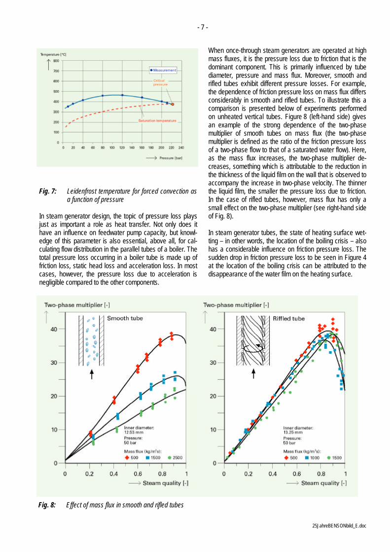
Fig. 7: Leidenfrost temperature for forced convection asa function of pressure
In steam generator design, the topic of pressure loss playsjust as important a role as heat transfer. Not only does ithave an influence on feedwater pump capacity, but knowl-edge of this parameter is also essential, above all, for cal-culating flow distribution in the parallel tubes of a boiler. Thetotal pressure loss occurring in a boiler tube is made up offriction loss, static head loss and acceleration loss. In mostcases, however, the pressure loss due to acceleration isnegligible compared to the other components.
When once-through steam generators are operated at highmass fluxes, it is the pressure loss due to friction that is thedominant component. This is primarily influenced by tubediameter, pressure and mass flux. Moreover, smooth andrifled tubes exhibit different pressure losses. For example,the dependence of friction pressure loss on mass flux differsconsiderably in smooth and rifled tubes. To illustrate this acomparison is presented below of experiments performedon unheated vertical tubes. Figure 8 (left-hand side) givesan example of the strong dependence of the two-phasemultiplier of smooth tubes on mass flux (the two-phasemultiplier is defined as the ratio of the friction pressure lossof a two-phase flow to that of a saturated water flow). Here,as the mass flux increases, the two-phase multiplier de-creases, something which is attributable to the reduction inthe thickness of the liquid film on the wall that is observed toaccompany the increase in two-phase velocity. The thinnerthe liquid film, the smaller the pressure loss due to friction.In the case of rifled tubes, however, mass flux has only asmall effect on the two-phase multiplier (see right-hand sideof Fig. 8).
In steam generator tubes, the state of heating surface wet-ting – in other words, the location of the boiling crisis – alsohas a considerable influence on friction pressure loss. Thesudden drop in friction pressure loss to be seen in Figure 4at the location of the boiling crisis can be attributed to thedisappearance of the water film on the heating surface.
Fig. 8: Effect of mass flux in smooth and rifled tubes

- 8 -
25JahreBENSONbild_E.doc
Investigation of these briefly outlined design aspects forfossil-fired steam generators required – as illustrated inFigure 9 – extensive experiments on tubes with differentgeometries, modes of heating and orientations over a widerange of operating parameters. The system pressures andmass fluxes were chosen such as to envelop the entireoperating range of a steam generator from full load to ex-tremely low part load. In connection with tube heating, con-ditions that arise in so-called "hot spots" were also ac-counted for. Furthermore, the tubes that were investigatedhad inside diameters of the kind found in both once-throughand recirculating steam generators. Data from 100,000measurements taken on smooth tubes as well as 140,000measurements on rifled tubes (as of the end of 1999) havebeen compiled to form an extensive database on wall tem-peratures and pressure losses which serves as a basis fordeveloping software for the fields of thermal hydraulics andfluid dynamics.
Fig. 9: Overview of heat transfer tests
The BENSON test rig was also used to conduct investiga-tions of the behavior of membrane waterwalls with integralsupports under transient loading conditions. In these tests,measurements were taken of the time-dependent tempera-tures and stresses arising in sections of the membranewaterwalls with their supports. The results of these investi-gations serve as a basis for calculating the thermal stressesinduced in these components during boiler startup andshutdown.
Another series of tests carried out at the BENSON test rigthat is also worthy of mention concerned a new compactmeasuring system, basically consisting of a venturi tube anda one-beam gamma densitometer (see Fig. 10), that can
Fig. 10: Wet steam measuring system
help improve feedwater control in once-through steam gen-erators /7/.
Up until now it has been common practice to use the steamenthalpy – some manufacturers also use the steam tem-perature – downstream of the boiler section as an inputvariable for feedwater control. However, in order to be surethat these measurements are always taken in a super-heated steam environment, even during dynamic proc-esses, the instrumentation for this control variable must belocated in the primary superheating section, e.g. betweenthe high-pressure superheaters. The disadvantage of this isthat response is slower to changes in heat input inside thefurnace and thus to changes in primary superheater steamenthalpy. Processes of heat storage and heat removal oc-curring inside the boiler section cannot be monitored.
The measuring system developed by Framatome ANPmeasures not only the pressure and the temperature butalso the mass flow and the steam quality of wet steam. Thesystem can be installed at the end of the boiler section (up-stream of the moisture separators or even between individ-ual boiler sections) for either full-flow or part-flow measure-ment, and supplies data on all variables needed for feed-water control. The measuring system tested at the BENSONtest rig and later also in a power plant is characterized bythe following features:

- 9 -
25JahreBENSONbild_E.doc
• Compact and operationally safe design which is simpleto use,
• Easy interpretation of measured data, and• Wide range of measurement.
Compared to the conventional method of enthalpy meas-urement, the wet steam measuring system also provides thefollowing advantages:
• Only a small delay between changes in heat input insidethe furnace and the consequences of such changes inthe steam, condensate and feedwater cycle, thus mak-ing feedwater control response extremely fast.
• Processes of heat storage and heat removal occurringinside the boiler section can be monitored. The meas-ured data can be quickly processed and used as inputsfor attemperator control.
When this wet steam measuring system is installed near theend of the boiler section, faster rates of load change arepossible (while at the same time preventing excessivestressing of the HP superheater materials) than when tradi-tional methods for measuring enthalpy or temperature at thehigh-pressure superheaters are used.
Example 2: Contributions to the Safety of New andOperating Nuclear Power Plants
The high-pressure test facility can be employed not only fortopics associated with fossil-fired power plants but also forsafety-related tasks for new nuclear power plant designs ornuclear plants already in operation. Tests have been per-formed, for example, to measure the influence of fouling onsecondary-side heat transfer using part of a steam genera-tor tube that had actually been in service. Another project
involved determining the cladding tube temperatures ofsimulated fuel assembly segments using spacer gridsequipped with different swirl vanes.
Recent investigations have shown that, under certainboundary conditions, light water reactors possess safetymargins in the event of a beyond-design accident whichhave not previously been taken into account. Until now, no-one had been able to properly explain why, during the acci-dent at Three Mile Island (TMI) in 1979, the wall of the re-actor pressure vessel (RPV) did not start to melt eventhough around 20 tons of molten core material had slumpedinto the lower plenum and a corresponding amount of decayheat required removal.
What had already been verified was that the molten corematerial formed a crust when it came into contact with thewater still present inside the RPV, resulting in gaps arisingbetween the porous crust of the molten material and theRPV wall. Thanks to the experiments carried out at theBENSON test rig, however, an explanation has now beenfound: namely that, in a case such as this, the intensivecooling effect provided by evaporation of the water is suffi-cient to remove enough of the decay heat so that overheat-ing of the RPV wall does not occur /8/.
For experimentally verifying the phenomenon of gap cool-ing, a specially designed test replica was integrated into thetest facility (Fig. 11). This allowed the width of the gap be-tween the simulated debris crust and the RPV wall, as wellas the system pressure, to be varied within the ranges ap-plying to this accident.
Fig. 11: Test setup to simulate heat removal during TMI accident
- 10 -
25JahreBENSONbild_E.doc
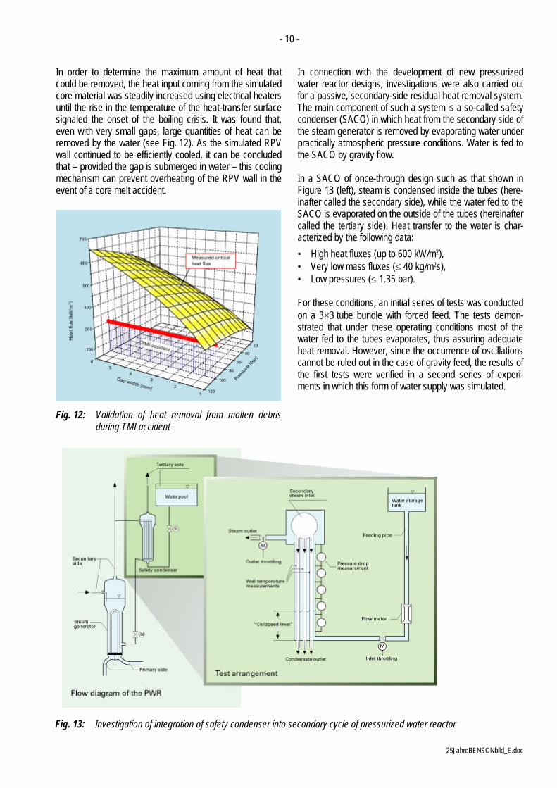
In order to determine the maximum amount of heat thatcould be removed, the heat input coming from the simulatedcore material was steadily increased using electrical heatersuntil the rise in the temperature of the heat-transfer surfacesignaled the onset of the boiling crisis. It was found that,even with very small gaps, large quantities of heat can beremoved by the water (see Fig. 12). As the simulated RPVwall continued to be efficiently cooled, it can be concludedthat – provided the gap is submerged in water – this coolingmechanism can prevent overheating of the RPV wall in theevent of a core melt accident.
Fig. 12: Validation of heat removal from molten debrisduring TMI accident
In connection with the development of new pressurizedwater reactor designs, investigations were also carried outfor a passive, secondary-side residual heat removal system.The main component of such a system is a so-called safetycondenser (SACO) in which heat from the secondary side ofthe steam generator is removed by evaporating water underpractically atmospheric pressure conditions. Water is fed tothe SACO by gravity flow.
In a SACO of once-through design such as that shown inFigure 13 (left), steam is condensed inside the tubes (here-inafter called the secondary side), while the water fed to theSACO is evaporated on the outside of the tubes (hereinaftercalled the tertiary side). Heat transfer to the water is char-acterized by the following data:
• High heat fluxes (up to 600 kW/m2),• Very low mass fluxes (≤ 40 kg/m2s),• Low pressures (≤ 1.35 bar).
For these conditions, an initial series of tests was conductedon a 3×3 tube bundle with forced feed. The tests demon-strated that under these operating conditions most of thewater fed to the tubes evaporates, thus assuring adequateheat removal. However, since the occurrence of oscillationscannot be ruled out in the case of gravity feed, the results ofthe first tests were verified in a second series of experi-ments in which this form of water supply was simulated.
Fig. 13: Investigation of integration of safety condenser into secondary cycle of pressurized water reactor

- 11 -
25JahreBENSONbild_E.doc
In order to simulate all hydrostatic effects realistically, allsystem elevations such as the elevation of the water stor-age tank, the relative elevations of the water feed line inletand outlet, and the active height of the SACO were scaled1:1. The final test setup is shown in detail on the right ofFigure 13. Whereas the tertiary side, in which atmosphericpressure conditions prevail, operated as a function of differ-ences in hydrostatic pressure, the secondary side of theSACO was connected to the high-pressure side of theBENSON test rig. The heat coming from the steam genera-tor was simulated by electrically heating the tube bundlewith a heat input of 1.3 MW. The following aspects wereinvestigated:
• The performance characteristics of the SACO, i.e. itsheat-exchange behavior as a function of secondary-sidepressure, water feed rate and exit resistance
• Its heat-exchange characteristics for various initial con-ditions.
In this steam condenser, which operates according to theonce-through principle, the heat-exchange behavior is pri-marily governed by the occurrence of the boiling crisis. If theboiling crisis should already occur in an area of low steamquality, a large proportion of the water fed to the condenserwill pass through the heat exchanger without absorbingheat. The reason for this is that film or transition boilingoccurs in the region above the zone with a wetted heatingsurface (subcooled boiling and saturation boiling), resultingin much less heat being transferred per unit of heat-exchange surface. However, if the boiling crisis should notoccur until an area of high steam quality is reached, most ofthe water will be evaporated, thus assuring good heat re-moval. As was shown by the experiments, the latter of thesetwo cases applies to the SACO. The tests also verified thatheat transfer performance is not affected by the method ofwater supply (Fig. 14).
Fig. 14: Performance characteristics of SACO
If the heat-exchange data measured at the 3×3 tube bundleare extrapolated to apply to the entire SACO, then it can beexpected to have a heat-removal capacity of 50 to 55 MW atsecondary-side pressures starting from 25 bar and nearly30 MW at a pressure of 5 bar /9/.
Thus the tests verified that a safety condenser operating onthe once-through principle meets the requirements stipu-lated for such a component as regards adequacy of heatremoval.
Another safety-related contribution has concerned leakdetection in nuclear power plants using acoustic leakagemonitoring systems. To reliably detect the presence of rup-tures and thus prevent further damage to the ruptured com-ponent itself or to components in the immediate vicinity, it isnecessary to be able, on the one hand, to calculate theanticipated discharge rates and, on the other, to correlatethese with signals from leakage monitoring systems. Cal-culating such discharge rates using the models available inthe literature is problematical since most of the underlyinginvestigations were not performed on real cracks but onopenings of a predefined geometry, such as orifice plates.In addition, model validation has been lacking in the rangeof parameters that is of interest for engineering processes,such as high pressures. For these reasons, tests usingwater and steam were carried out at the high-pressure testfacility with the aim of obtaining, for a wide range of pa-rameters, information on discharge rates as a function ofstagnation pressure and temperature as well as hydraulicresistance (crack opening geometry, surface roughness,etc.).
In addition, measurements of noise were taken during theexperiments using a variety of different sensors in order todetermine the relationship between discharge rate andleakage noise and thus document the applicability of acous-tic leakage monitoring systems /10, 11/.
Example 3: Power Plant Concepts for Direct SolarSteam Generation
One of the options for integrating solar thermal technologiesinto the power plant market in countries of the sunbelt cancomprise the following concept. A fossil-fired power plant(e.g. a combined-cycle plant) is used for base and interme-diate load service. When solar radiation is sufficiently high,the sun's rays are concentrated by a trough collector andused to generate steam for cutting down fuel consumptionor meeting mid-day peak demand.
Up until now, thermal oil has been heated in absorber tubesand steam has been generated in a heat exchanger in-stalled in a separate circuit. However, economical solarsteam generation can only be expected from systems inwhich the solar energy is used to directly evaporate water
- 12 -
25JahreBENSONbild_E.doc
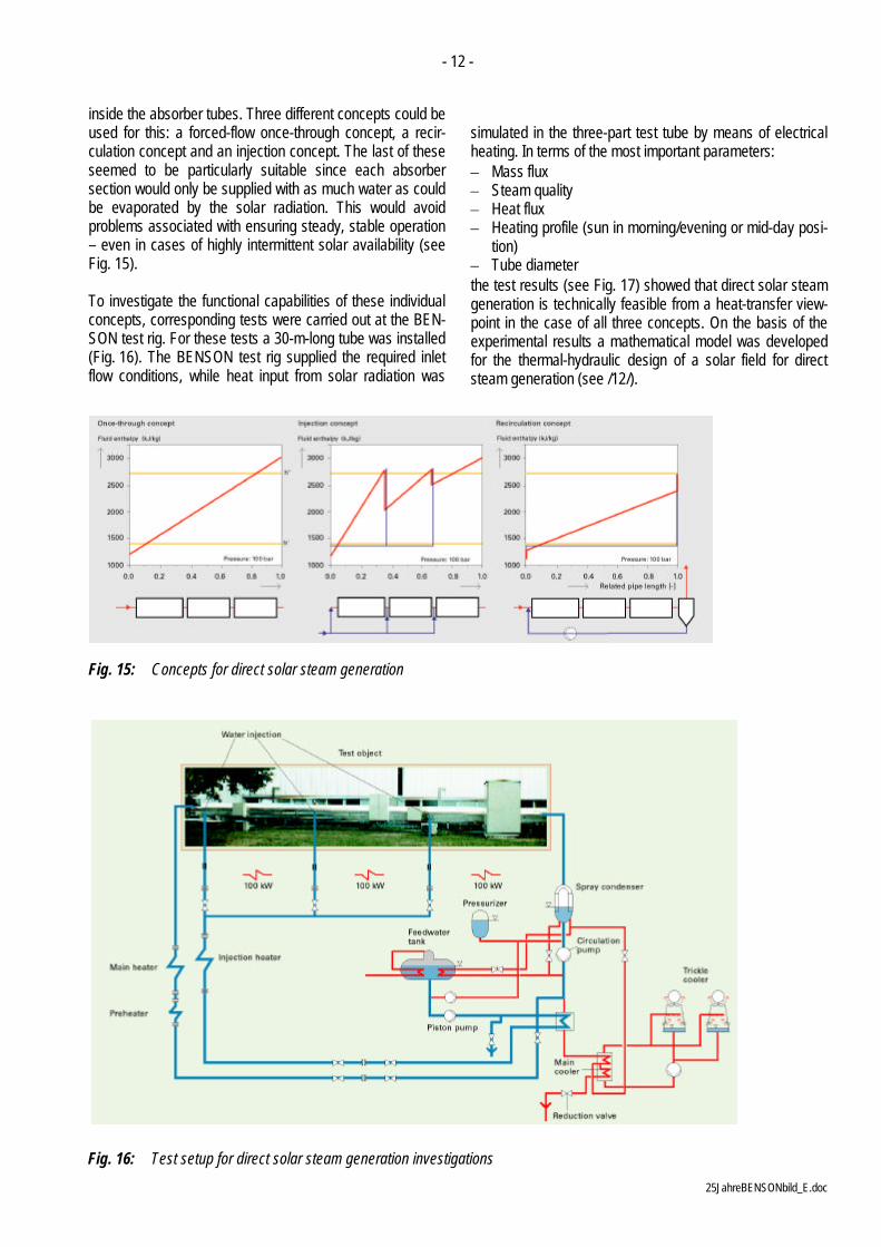
inside the absorber tubes. Three different concepts could beused for this: a forced-flow once-through concept, a recir-culation concept and an injection concept. The last of theseseemed to be particularly suitable since each absorbersection would only be supplied with as much water as couldbe evaporated by the solar radiation. This would avoidproblems associated with ensuring steady, stable operation– even in cases of highly intermittent solar availability (seeFig. 15).
To investigate the functional capabilities of these individualconcepts, corresponding tests were carried out at the BEN-SON test rig. For these tests a 30-m-long tube was installed(Fig. 16). The BENSON test rig supplied the required inletflow conditions, while heat input from solar radiation was
simulated in the three-part test tube by means of electricalheating. In terms of the most important parameters:– Mass flux– Steam quality– Heat flux– Heating profile (sun in morning/evening or mid-day posi-
tion)– Tube diameterthe test results (see Fig. 17) showed that direct solar steamgeneration is technically feasible from a heat-transfer view-point in the case of all three concepts. On the basis of theexperimental results a mathematical model was developedfor the thermal-hydraulic design of a solar field for directsteam generation (see /12/).
Fig. 15: Concepts for direct solar steam generation
Fig. 16: Test setup for direct solar steam generation investigations
- 13 -
25JahreBENSONbild_E.doc
Fig. 17: Temperatures at upper side of absorber tube
Example 4: Wet Steam Piping Networks for ThermallyEnhanced Heavy-Oil Recovery
One of the methods employed for recovering heavy oil – forexample, in Venezuela – is that of injecting steam into theoil reservoir. The steam, which is injected through bore-holes, increases the reservoir pressure and lowers the vis-cosity of the oil. This enables oils of originally high viscosityto be recovered from oil sands and oil shale.
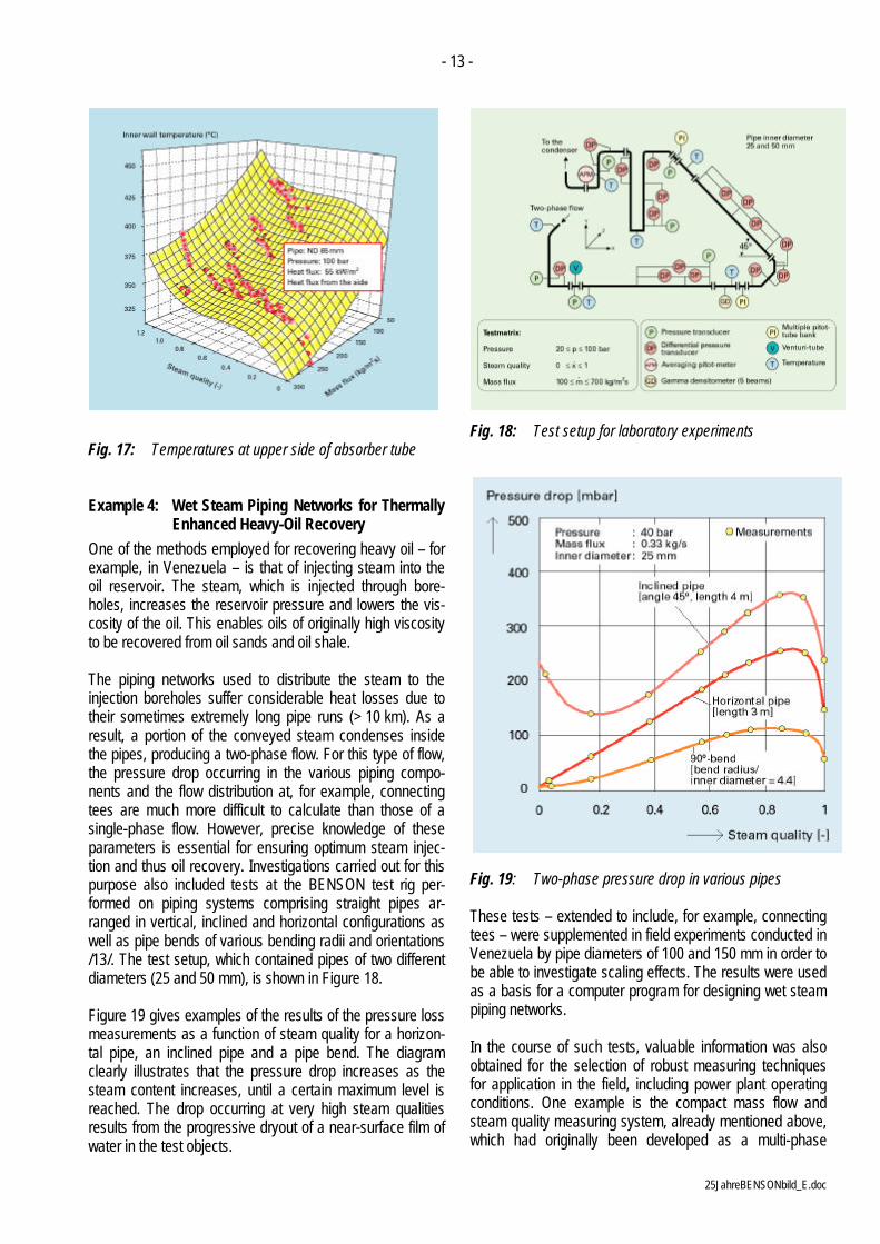
The piping networks used to distribute the steam to theinjection boreholes suffer considerable heat losses due totheir sometimes extremely long pipe runs (> 10 km). As aresult, a portion of the conveyed steam condenses insidethe pipes, producing a two-phase flow. For this type of flow,the pressure drop occurring in the various piping compo-nents and the flow distribution at, for example, connectingtees are much more difficult to calculate than those of asingle-phase flow. However, precise knowledge of theseparameters is essential for ensuring optimum steam injec-tion and thus oil recovery. Investigations carried out for thispurpose also included tests at the BENSON test rig per-formed on piping systems comprising straight pipes ar-ranged in vertical, inclined and horizontal configurations aswell as pipe bends of various bending radii and orientations/13/. The test setup, which contained pipes of two differentdiameters (25 and 50 mm), is shown in Figure 18.
Figure 19 gives examples of the results of the pressure lossmeasurements as a function of steam quality for a horizon-tal pipe, an inclined pipe and a pipe bend. The diagramclearly illustrates that the pressure drop increases as thesteam content increases, until a certain maximum level isreached. The drop occurring at very high steam qualitiesresults from the progressive dryout of a near-surface film ofwater in the test objects.
Fig. 18: Test setup for laboratory experiments
Fig. 19: Two-phase pressure drop in various pipes
These tests – extended to include, for example, connectingtees – were supplemented in field experiments conducted inVenezuela by pipe diameters of 100 and 150 mm in order tobe able to investigate scaling effects. The results were usedas a basis for a computer program for designing wet steampiping networks.
In the course of such tests, valuable information was alsoobtained for the selection of robust measuring techniquesfor application in the field, including power plant operatingconditions. One example is the compact mass flow andsteam quality measuring system, already mentioned above,which had originally been developed as a multi-phase

- 14 -
25JahreBENSONbild_E.doc
measuring device for oil, water and gas flow and content inoffshore oil production systems and was later tested underpower plant operating conditions for use in once-throughboilers.
Example 5: Effects of Water Chemistry on ProtectiveSurface Layers and Investigations ofComponent Materials
Via the chemical dosing point shown in Figure 1 it is possi-ble for any desired water chemistry to be established in theBENSON test rig which is made entirely of austenitic mate-rial. This option was used for a variety of experimental tasksrelated, for example, to:– Formation of protective magnetite layers inside tubes– Behavior of protective layers in the event of thermal
shocks
– Material loss due to erosion corrosion.
The last of these topics is briefly addressed below.
Erosion corrosion can be defined as the loss of materialfrom solid surfaces through corrosive dissolution under theconvective action of single-phase liquid flows /14/. It ischaracterized by the corrosive dissolution of protective sur-face films or parts thereof. In addition to this, it requires thepresence of a turbulent, single-phase liquid flow adjacentthe surface which is, however, also possible in wet steamregions, e.g. in areas of annular flow (ring of water at pipewall and steam at the core of the flow) or of partial steady-state wetting. Erosion corrosion is a phenomenon restrictedsolely to metals whose resistance to corrosion depends onthe formation of protective oxide layers such as magnetite.
Fig. 20: Wall thinning due to erosion corrosion (effects of thermal-hydraulic and water chemistry parameters)

- 15 -
25JahreBENSONbild_E.doc
To investigate the parameters influencing the process oferosion corrosion, tests were conducted on the BENSONtest rig on various objects (flat plates oriented in the direc-tion of flow, tubes, bends, reducers and increasers) underconditions of water and steam-water flow /15/. The materialloss caused by erosion corrosion was determined by differ-ent measuring techniques. In addition to weighing and directwall thickness measurement, the so-called Thin Layer Acti-vation (TLA) technique was also employed. This methodallows continuous measurement of material losses at alayer of the surface that has been activated through irradia-tion with radioisotopes.
The tests focused in particular on investigating the effects offlow velocity, fluid temperature and water chemistry (pH andoxygen content). In addition, the resistance of various mate-rials (around 15) was compared and the resistance of pro-tective magnetite layers to erosion corrosion was investi-gated. The results of these extensive investigations – someexamples are shown in Figure 20 – were used to develop acomputer program which can be employed in power plantdesign to ensure that no significant damage due to erosioncorrosion will occur during the plant's design service life.The program can also be applied for existing power plantsto identify locations on components at which the wall thick-ness should be monitored, meaning that the scope of in-service inspections can be reduced to cover just those loca-tions at which measurements are absolutely necessary.Finally, the program can likewise be used to optimize as-pects related, for example, to materials, design or waterchemistry regimes for component repair or replacementactivities that might become necessary /16/.
In addition to the above, it should be mentioned that the testrig can also be employed for determining the material prop-erties of components. One example has been tests carriedout to determine the thermal conductivity of materials fornuclear steam generator tubes.
ConclusionThe broad and impressive range of applications for whichthe high-pressure test facility (330 bar, 600°C, 28 kg/s,2 MW) installed in an accredited laboratory at FramatomeANP in Erlangen can be used underlines the flexibility of thistest rig which, at the start of the new millennium, had beenin operation for 25 years and will continue to be available fornew research and development work in the future. Theresults of the investigations performed at the test facilityhave enabled pioneering findings related to the design andoperation of power plants using nuclear, fossil and renew-able energy sources as well as other industrial facilities tobe made. The quality of the experimental data allows themto be used as a basis for developing computer programs fora wide variety of different issues.
References
/1/ H. Griem, W. Köhler, H. SchmidtHeat Transfer, Pressure Drop and Stresses inEvaporator Water Walls.VGB PowerTech 79 (1999) 1, pp. 26 - 35.
/2/ W. Köhler, V. Kefer, W. KastnerHeat Transfer in Vertical and Horizontal One-Side-Heated Evaporator TubesExperimental Heat Transfer 3 (1990), pp. 397 - 409
/3/ V. Kefer, W. Köhler, W. KastnerCritical Heat Flux (CHF) and Post-CHF Heat Trans-fer in Horizontal and Inclined Evaporator TubesInt. J. Multiphase Flow 15 (1989) 3, pp. 385 - 392
/4/ W. Köhler and W. KastnerHeat Transfer and Pressure Loss in Rifled Tubes8th Int. Heat Transfer Conference, San Francisco,USA (1986), Vol. 6, pp. 2861 - 2865
/5/ J. Franke, W. Köhler, E. WittchowEvaporator Design for BENSON-Boilers – State ofthe Art and Latest Development TrendsVGB KraftwerksTechnik 73 (1993) 4, pp. 307 - 315
/6/ D. Hein, V. Kefer, J. LiebertMaximum Wetting Temperatures up toCritical Pressure1st Int. Workshop on Fundamental Aspects of Post-Dryout Heat Transfer, Salt Lake City, Utah, USA,1984, NUREG/CP-0060, pp. 118 - 136
/7/ W. Kastner, C. Fischer, W. KrätzerVerbesserte Speisewasserregelung durchkompaktes Meßsystem zur Massenstrom- undDampfgehaltsbestimmungBWK 45 (1993) 12, pp. 510 - 514
/8/ H. Schmidt, W. Köhler, O. Herbst, W. KrätzerExperiments on Heat Removal in a Gap betweenDebris Crust and RPV Wall1st European-Japanese Two-Phase Flow GroupMeeting,35th European Two-Phase Flow Group Meeting,Portoroz, Slovenia, June 1-5, 1998, Paper F-4
/9/ W. Köhler, O. Herbst. W. KastnerThermal-Hydraulic Behavior of a Safety CondenserInt. Conf. on New Trends in Nuclear System Thermo-hydraulics, Pisa, Italy, May 30 to June 2, 1994,Proc. Vol. 1, pp. 609 - 614

- 16 -
25JahreBENSONbild_E.doc
/10/ V. Kefer, W. KastnerLeckagen bei unterkritischen Rohrleitungsrissen –Ausströmraten und ihre GeräuscheBWK 39 (1987) 6, pp. 310 - 315
/11/ V. Kefer, W. Kastner, F. Westphal, H. John,J. Reimann, L. FriedelVorhersagegenauigkeit von Modellen für Leckratenaus Rissen in druckführenden KomponentenDECHEMA – Monographien, Band 111,Fortschritte der Sicherheitstechnik II, Frankfurt, 1988
/12/ W. Köhler, O. Herbst, W. KastnerThermal Design of Solar Absorber Tubes with DirectSteam Generation8th Int. Symp. on Solar Thermal Concentrating Tech-nologies, Cologne, Germany, Oct. 6 to 11, 1996
/13/ M. Gonzales, W. Kastner, et al.Upgrading of Venezuelan Crude Oil – Continuationof the Orinoco Feasibility Study within the Venezue-lan/German Agreement (Annex III B)Final Report BMFT Reference No. 03E-6400B,June 1989
/14/ H.-G. Heitmann, W. KastnerErosion-Corrosion in Water-Steam Cycles– Causes and Countermeasures -VGB KraftwerksTechnik 62 (1982) 3, pp. 180 - 187
/15/ W. Kastner, K. Riedle, H. TratzExperimental Investigations on Material Loss due toErosion-Corrosion.VGB KraftwerksTechnik 64 (1984) 5, pp. 411 - 423
/16/ W. Kastner, H. Nopper, R. RößnerVermeiden von Erosionskorrosionsschäden inRohrleitungen3R international 33 (1994) 8, pp. 423 - 428