high-power series pneumatic series air hydraulic … hydraulic unit with a non-leak valve can hold...
TRANSCRIPT
AirSequence Valve
BWD
HydraulicNon-Leak Coupler
BGA/BGB
BGC/BGD
BGP/BGS
BBP/BBS
BNP/BNS
BJP/BJS
BFP/BFS
Auto Coupler
JVC/JVD
JVA/JVB
JVE/JVF
JNA/JNB
JNC/JND
JLP/JLS
Hydraulic Valve
BK
BEQ
BT
BLS/BLG
BLB
JSS/JS
JKA/JKB
BMA/BMG
AU/AU-M
BU
AirHydraulic Unit
CV
CK
CP/CPB
CPC/CQC
CB
CC
AB/AB-V
AC/AC-V
Rotary Joint
JR
BP/JPB
BX
BEP/BSP
BH
BC
Pneumatic Series
Hydraulic Series
Valve / CouplerHydraulic Unit
Cautions / Others
High-PowerSeries
Manual OperationAccessories
Air Hydraulic UnitDigest
Discharge Pressure
64.7MPa
2.3MPa
0L/min 16L/min
10MPa
4L/min
8L/min
12L/min
20MPa
30MPa
40MPa
50MPa
60MPa
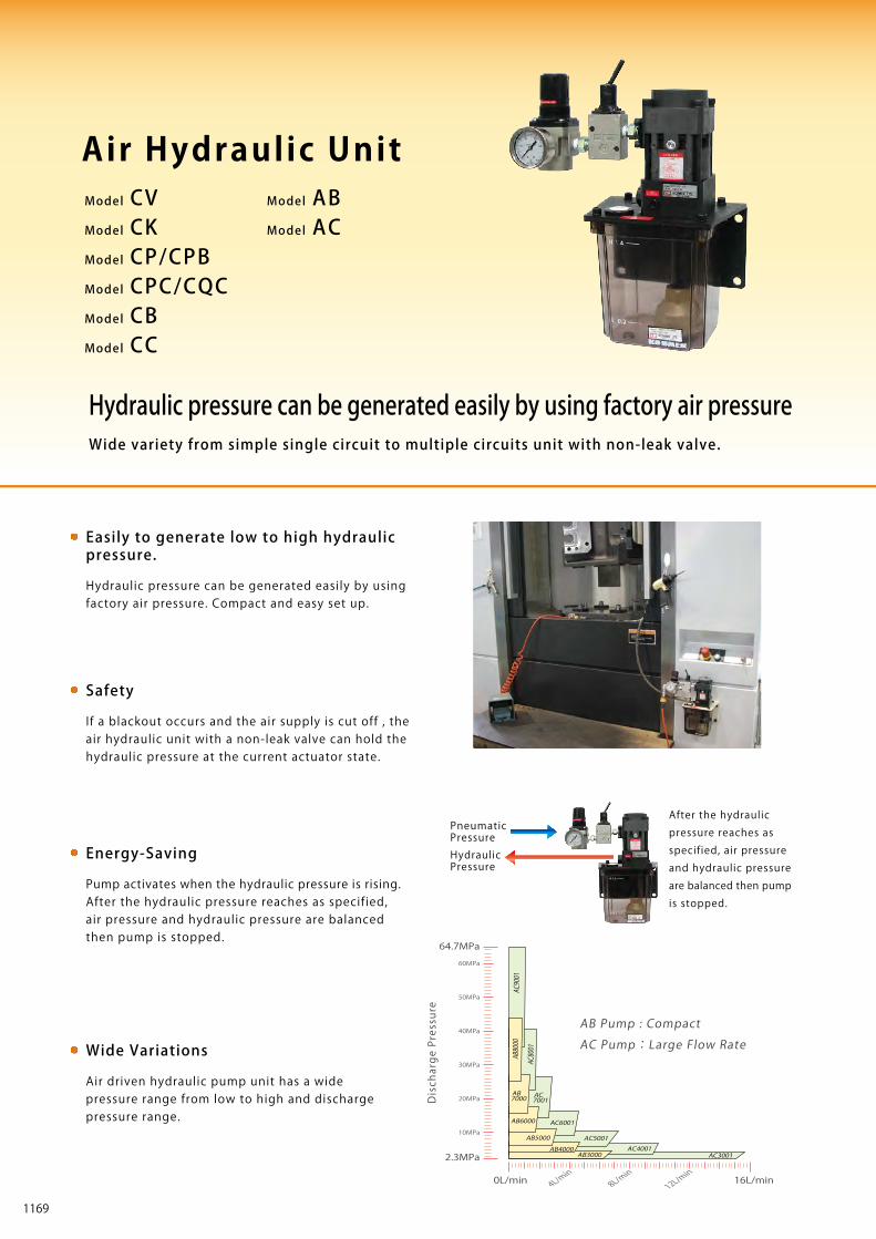
Hydraulic pressure can be generated easily by using factory air pressureWide variety from simple single circuit to multiple circuits unit with non-leak valve.
Easily to generate low to high hydraulic pressure.
Hydraulic pressure can be generated easily by using factory air pressure. Compact and easy set up.
Energy-Saving
Pump activates when the hydraulic pressure is rising. After the hydraulic pressure reaches as specified, air pressure and hydraulic pressure are balanced then pump is stopped.
Wide Variations
Air driven hydraulic pump unit has a wide pressure range from low to high and discharge pressure range.
Safety
If a blackout occurs and the air supply is cut off , the air hydraulic unit with a non-leak valve can hold the hydraulic pressure at the current actuator state.
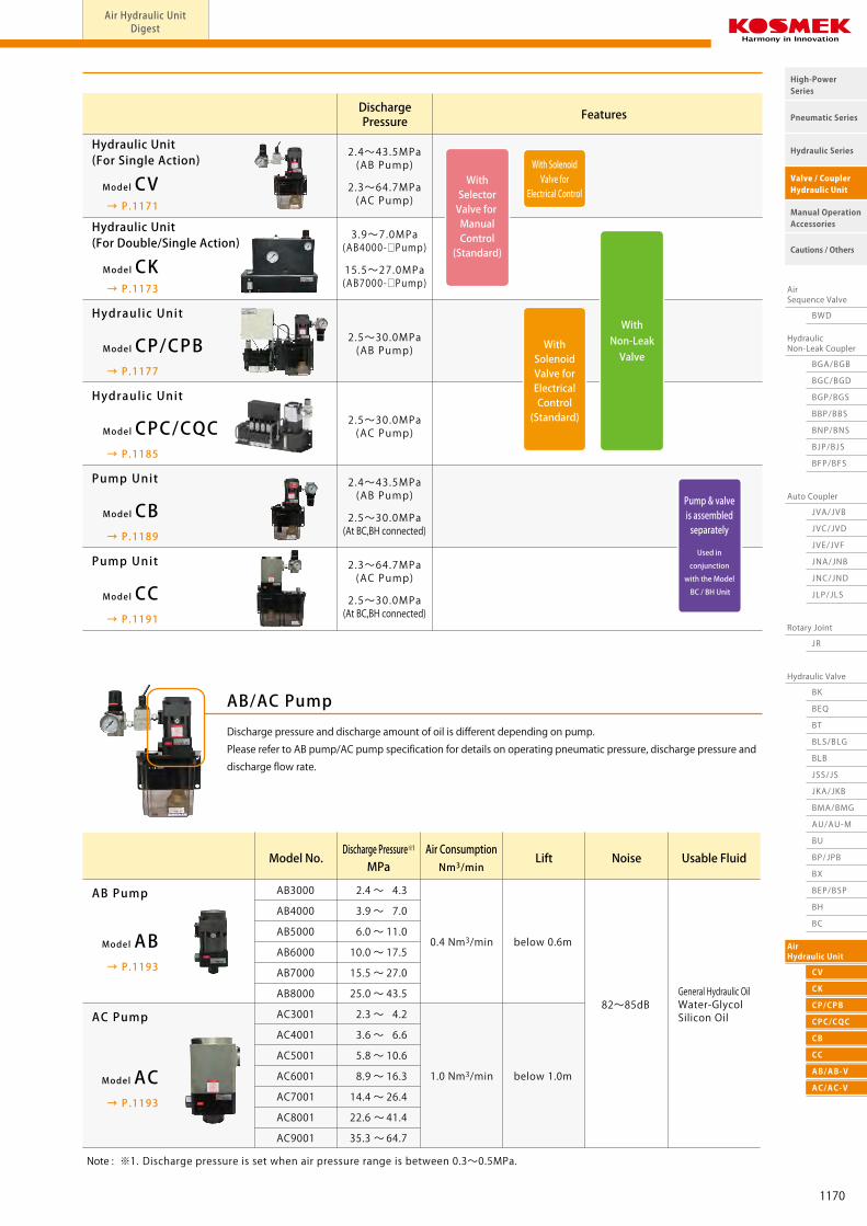
Discharge pressure and discharge amount of oil is different depending on pump.
Please refer to AB pump/AC pump specification for details on operating pneumatic pressure, discharge pressure and
discharge flow rate.
AB/AC Pump
Pneumatic Pressure
HydraulicPressure
After the hydraulic
pressure reaches as
specified, air pressure
and hydraulic pressure
are balanced then pump
is stopped.
Model ABModel AC
Air Hydraulic UnitModel CV
Model CK
Model CB
Model CC
DischargePressure Features
2.4~43.5MPa(AB Pump)
2.5~30.0MPa(AB Pump)
2.5~30.0MPa(AC Pump)
Hydraulic Unit (For Single Action)
Hydraulic Unit (For Double/Single Action)
Hydraulic Unit
Pump Unit
Hydraulic Unit
Pump Unit
2.3~64.7MPa(AC Pump)
3.9~7.0MPa(AB4000-□Pump)
15.5~27.0MPa(AB7000-□Pump)
2.4~43.5MPa(AB Pump)
2.5~30.0MPa(At BC,BH connected)
2.3~64.7MPa(AC Pump)
2.5~30.0MPa(At BC,BH connected)
→ P.1171
→ P.1173
Model AB
Model AC
Model No. Lift Noise Usable FluidDischarge Pressure※1
MPaAir ConsumptionNm3/min
0.4 Nm3/min
AB3000
AB4000
AB5000
AB6000
AB7000
AB8000
AC3001
AC4001
AC5001
AC6001
AC7001
AC8001
AC9001
2.4 ~ 4.3
3.9 ~ 7.0
6.0 ~ 11.0
10.0 ~ 17.5
15.5 ~ 27.0
25.0 ~ 43.5
2.3 ~ 4.2
3.6 ~ 6.6
5.8 ~ 10.6
8.9 ~ 16.3
14.4 ~ 26.4
22.6 ~ 41.4
35.3 ~ 64.7
AB Pump
→ P.1193
→ P.1193
→ P.1177
→ P.1185
→ P.1189
→ P.1191
1.0 Nm3/min
WithNon-LeakValve
WithSelectorValve for ManualControl(Standard)
WithSolenoidValve forElectricalControl(Standard)
With SolenoidValve for
Electrical Control
below 0.6m
below 1.0m
82~85dBGeneral Hydraulic OilWater-GlycolSilicon OilAC Pump
Note : ※1. Discharge pressure is set when air pressure range is between 0.3~0.5MPa.
AB3000 AC3001AB4000 AC4001
AC5001
AC6001
AC7001
AB5000
AB6000
AB8000
AC8001
AC9001
AB7000
AB Pump : Compact
AC Pump:Large Flow Rate
Used in
conjunction
with the Model
BC / BH Unit
Pump & valveis assembledseparately
Model CVModel CKModel CP/CPBModel CPC/CQCModel CBModel CC Model CP/CPB
Model CPC/CQC
1169
AirSequence Valve
BWD
HydraulicNon-Leak Coupler
BGA/BGB
BGC/BGD
BGP/BGS
BBP/BBS
BNP/BNS
BJP/BJS
BFP/BFS
Auto Coupler
JVC/JVD
JVA/JVB
JVE/JVF
JNA/JNB
JNC/JND
JLP/JLS
Hydraulic Valve
BK
BEQ
BT
BLS/BLG
BLB
JSS/JS
JKA/JKB
BMA/BMG
AU/AU-M
BU
AirHydraulic Unit
CV
CK
CP/CPB
CPC/CQC
CB
CC
AB/AB-V
AC/AC-V
Rotary Joint
JR
BP/JPB
BX
BEP/BSP
BH
BC
Pneumatic Series
Hydraulic Series
Valve / CouplerHydraulic Unit
Cautions / Others
High-PowerSeries
Manual OperationAccessories
Air Hydraulic UnitDigest
Discharge Pressure
64.7MPa
2.3MPa
0L/min 16L/min
10MPa
4L/min
8L/min
12L/min
20MPa
30MPa
40MPa
50MPa
60MPa
Hydraulic pressure can be generated easily by using factory air pressureWide variety from simple single circuit to multiple circuits unit with non-leak valve.
Easily to generate low to high hydraulic pressure.
Hydraulic pressure can be generated easily by using factory air pressure. Compact and easy set up.
Energy-Saving
Pump activates when the hydraulic pressure is rising. After the hydraulic pressure reaches as specified, air pressure and hydraulic pressure are balanced then pump is stopped.
Wide Variations
Air driven hydraulic pump unit has a wide pressure range from low to high and discharge pressure range.
Safety
If a blackout occurs and the air supply is cut off , the air hydraulic unit with a non-leak valve can hold the hydraulic pressure at the current actuator state.
Discharge pressure and discharge amount of oil is different depending on pump.
Please refer to AB pump/AC pump specification for details on operating pneumatic pressure, discharge pressure and
discharge flow rate.
AB/AC Pump
Pneumatic Pressure
HydraulicPressure
After the hydraulic
pressure reaches as
specified, air pressure
and hydraulic pressure
are balanced then pump
is stopped.
Model ABModel AC
Air Hydraulic UnitModel CV
Model CK
Model CB
Model CC
DischargePressure Features
2.4~43.5MPa(AB Pump)
2.5~30.0MPa(AB Pump)
2.5~30.0MPa(AC Pump)
Hydraulic Unit (For Single Action)
Hydraulic Unit (For Double/Single Action)
Hydraulic Unit
Pump Unit
Hydraulic Unit
Pump Unit
2.3~64.7MPa(AC Pump)
3.9~7.0MPa(AB4000-□Pump)
15.5~27.0MPa(AB7000-□Pump)
2.4~43.5MPa(AB Pump)
2.5~30.0MPa(At BC,BH connected)
2.3~64.7MPa(AC Pump)
2.5~30.0MPa(At BC,BH connected)
→ P.1171
→ P.1173
Model AB
Model AC
Model No. Lift Noise Usable FluidDischarge Pressure※1
MPaAir ConsumptionNm3/min
0.4 Nm3/min
AB3000
AB4000
AB5000
AB6000
AB7000
AB8000
AC3001
AC4001
AC5001
AC6001
AC7001
AC8001
AC9001
2.4 ~ 4.3
3.9 ~ 7.0
6.0 ~ 11.0
10.0 ~ 17.5
15.5 ~ 27.0
25.0 ~ 43.5
2.3 ~ 4.2
3.6 ~ 6.6
5.8 ~ 10.6
8.9 ~ 16.3
14.4 ~ 26.4
22.6 ~ 41.4
35.3 ~ 64.7
AB Pump
→ P.1193
→ P.1193
→ P.1177
→ P.1185
→ P.1189
→ P.1191
1.0 Nm3/min
WithNon-LeakValve
WithSelectorValve for ManualControl(Standard)
WithSolenoidValve forElectricalControl(Standard)
With SolenoidValve for
Electrical Control
below 0.6m
below 1.0m
82~85dBGeneral Hydraulic OilWater-GlycolSilicon OilAC Pump
Note : ※1. Discharge pressure is set when air pressure range is between 0.3~0.5MPa.
AB3000 AC3001AB4000 AC4001
AC5001
AC6001
AC7001
AB5000
AB6000
AB8000
AC8001
AC9001
AB7000
AB Pump : Compact
AC Pump:Large Flow Rate
Used in
conjunction
with the Model
BC / BH Unit
Pump & valveis assembledseparately
Model CVModel CKModel CP/CPBModel CPC/CQCModel CBModel CC Model CP/CPB
Model CPC/CQC
1170
AirSequence Valve
BWD
HydraulicNon-Leak Coupler
BGA/BGB
BGC/BGD
BGP/BGS
BBP/BBS
BNP/BNS
BJP/BJS
BFP/BFS
Auto Coupler
JVC/JVD
JVA/JVB
JVE/JVF
JNA/JNB
JNC/JND
JLP/JLS
Hydraulic Valve
BK
BEQ
BT
BLS/BLG
BLB
JSS/JS
JKA/JKB
AU/AU-M
BU
AirHydraulic Unit
CV
Rotary Joint
JR
BP/JPB
BX
BEP/BSP
BH
BC
Pneumatic Series
Hydraulic Series
Valve / CouplerHydraulic Unit
Cautions / Others
High-PowerSeries
Manual OperationAccessories
AirSequence Valve
BWD
HydraulicNon-Leak Coupler
BGA/BGB
BGC/BGD
BGP/BGS
BBP/BBS
BNP/BNS
BJP/BJS
BFP/BFS
Auto Coupler
JVC/JVD
JVA/JVB
JVE/JVF
JNA/JNB
JNC/JND
JLP/JLS
Hydraulic Valve
BK
BEQ
BT
BLS/BLG
BLB
JSS/JS
JKA/JKB
BMA/BMG
AU/AU-M
BU
AirHydraulic Unit
CV
CK
CP/CPB
CPC/CQC
CB
CC
AB/AB-V
AC/AC-V
Rotary Joint
JR
BP/JPB
BX
BEP/BSP
BH
BC
Pneumatic Series
Hydraulic Series
Valve / CouplerHydraulic Unit
Cautions / Others
High-PowerSeries
Manual OperationAccessories
Air Hydraulic UnitDigest P.1169 Circuit Symbol External DimensionsModel No. Indication SpecificationsAir Hydraulic Unit Hydraulic Unit (For Single Action) model CV
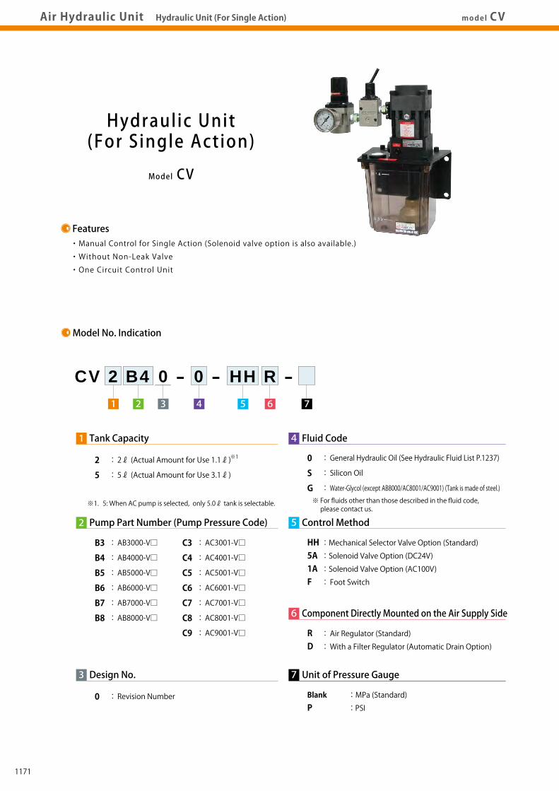
Model CV
Hydraulic Unit(For Single Action)
・Manual Control for Single Action (Solenoid valve option is also available.)
・Without Non-Leak Valve
・One Circuit Control Unit
Features
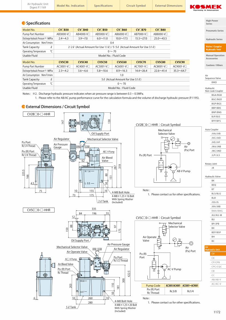
Specifications
CV2B□0-□-HHR:Circuit Symbol
CV5C□0-□-HHR:Circuit Symbol
External Dimensions / Circuit Symbol
MPaNm3/min
ℓ℃
Model No.Pump Part NumberDischarge Hydraulic Pressure ※2
Air ConsumptionTank CapacityOperating Temperature Usable Fluid
CV□B30 CV□B40 CV□B50 CV□B60 CV□B70 CV□B80 AB3000-V□ AB4000-V□ AB5000-V□ AB6000-V□ AB7000-V□ AB8000-V□ 2.4~4.3 3.9~7.0 6.0~11.0 10.0~17.5 15.5~27.0 25.0~43.5 0.4 2:2ℓ (Actual Amount for Use 1.1ℓ) / 5:5ℓ (Actual Amount for Use 3.1ℓ) 0 ~ 70 Model No. : Fluid Code
MPaNm3/min
ℓ℃
Model No.Pump Part NumberDischarge Hydraulic Pressure ※2
Air ConsumptionTank CapacityOperating Temperature Usable Fluid
CV5C30 CV5C40 CV5C50 CV5C60 CV5C70 CV5C80 CV5C90 AC3001-V□ AC4001-V□ AC5001-V□ AC6001-V□ AC7001-V□ AC8001-V□ AC9001-V□ 2.3~4.2 3.6~6.6 5.8~10.6 8.9~16.3 14.4~26.4 22.6~41.4 35.3~64.7 1.0 5ℓ (Actual Amount for Use 3.1ℓ) 0 ~ 70 Model No. : Fluid Code
Model No. Indication
1
1 2 4 6 753
Tank Capacity
2 : 2ℓ (Actual Amount for Use 1.1ℓ)
5 : 5ℓ (Actual Amount for Use 3.1ℓ)
CV 2 B4 0 - 0 - HH R -
3 Design No.
0 : Revision Number
2 Pump Part Number (Pump Pressure Code)
B3 : AB3000-V□
B4 : AB4000-V□
B5 : AB5000-V□
B6 : AB6000-V□
B7 : AB7000-V□
B8 : AB8000-V□
C3 : AC3001-V□
C4 : AC4001-V□
C5 : AC5001-V□
C6 : AC6001-V□
C7 : AC7001-V□
C8 : AC8001-V□
C9 : AC9001-V□
4 Fluid Code
0 : General Hydraulic Oil (See Hydraulic Fluid List P.1237)
S : Silicon Oil
G : Water-Glycol (except AB8000/AC8001/AC9001) (Tank is made of steel.)
5 Control Method
HH : Mechanical Selector Valve Option (Standard)5A : Solenoid Valve Option (DC24V)1A : Solenoid Valve Option (AC100V)F : Foot Switch
6 Component Directly Mounted on the Air Supply Side
R : Air Regulator (Standard)D : With a Filter Regulator (Automatic Drain Option)
7 Unit of Pressure Gauge
Blank : MPa (Standard)
P : PSI
Air(PA) Port
Air(PA) Port
PH (R) Port
PH (R) Port
AB-V Pump
AC-V Pump
Mechanical Selector Valve
※ For fluids other than those described in the fluid code, please contact us.
※1. 5: When AC pump is selected, only 5.0ℓ tank is selectable.
※1
Mechanical Selector Valve
Air Operate Valve
62
4.5
75 10 10155
80151
287
319
50
175
335
Oil Supply Port
1968412
260280
10106
55
159 97
175
422.5
300
181110
203
50
88
2ℓTank
5ℓTank
73
223.5
147
166
PA PortRc1/4 Thread
PA PortRc1/2 Thread
Oil Supply Port
Mechanical Selector ValveAir Regulator
Air PressureGauge
Air Bleed Valve
Air Bleed Valve
PH (R) PortRc1/4 Thread
CV2B□0-□-HHR
CV5C□0-□-HHR
AB□-V Pump
130
4-M8×1.25×16 BoltWith Spring Washer (Included)
4-M8 Bolt Hole
Mechanical Selector ValveAir Pressure Gauge
Air RegulatorAir Operate Valve
PH (R) PortRc Thread
AC□-V Pump
4-M8×1.25×20 BoltWith Spring Washer (Included)
4-M8 Bolt Hole
AC3001/AC4001
Rc3/8
Pump CodePH (R) PortRc Thread
AC5001~AC9001
Rc1/4
Note : 1. Please contact us for other specifications.
Note : 1. Please contact us for other specifications.
Notes : ※2. Discharge hydraulic pressure indicates when air pressure range is between 0.3 ~ 0.5MPa. 1. Please refer to the AB/AC pump performance curve for the calculation formula and the volume of discharge hydraulic pressure (P.1195).
1171
AirSequence Valve
BWD
HydraulicNon-Leak Coupler
BGA/BGB
BGC/BGD
BGP/BGS
BBP/BBS
BNP/BNS
BJP/BJS
BFP/BFS
Auto Coupler
JVC/JVD
JVA/JVB
JVE/JVF
JNA/JNB
JNC/JND
JLP/JLS
Hydraulic Valve
BK
BEQ
BT
BLS/BLG
BLB
JSS/JS
JKA/JKB
AU/AU-M
BU
AirHydraulic Unit
CV
Rotary Joint
JR
BP/JPB
BX
BEP/BSP
BH
BC
Pneumatic Series
Hydraulic Series
Valve / CouplerHydraulic Unit
Cautions / Others
High-PowerSeries
Manual OperationAccessories
AirSequence Valve
BWD
HydraulicNon-Leak Coupler
BGA/BGB
BGC/BGD
BGP/BGS
BBP/BBS
BNP/BNS
BJP/BJS
BFP/BFS
Auto Coupler
JVC/JVD
JVA/JVB
JVE/JVF
JNA/JNB
JNC/JND
JLP/JLS
Hydraulic Valve
BK
BEQ
BT
BLS/BLG
BLB
JSS/JS
JKA/JKB
BMA/BMG
AU/AU-M
BU
AirHydraulic Unit
CV
CK
CP/CPB
CPC/CQC
CB
CC
AB/AB-V
AC/AC-V
Rotary Joint
JR
BP/JPB
BX
BEP/BSP
BH
BC
Pneumatic Series
Hydraulic Series
Valve / CouplerHydraulic Unit
Cautions / Others
High-PowerSeries
Manual OperationAccessories
Air Hydraulic UnitDigest P.1169 Circuit Symbol External DimensionsModel No. Indication SpecificationsAir Hydraulic Unit Hydraulic Unit (For Single Action) model CV
Model CV
Hydraulic Unit(For Single Action)
・Manual Control for Single Action (Solenoid valve option is also available.)
・Without Non-Leak Valve
・One Circuit Control Unit
Features
Specifications
CV2B□0-□-HHR:Circuit Symbol
CV5C□0-□-HHR:Circuit Symbol
External Dimensions / Circuit Symbol
MPaNm3/min
ℓ℃
Model No.Pump Part NumberDischarge Hydraulic Pressure ※2
Air ConsumptionTank CapacityOperating Temperature Usable Fluid
CV□B30 CV□B40 CV□B50 CV□B60 CV□B70 CV□B80 AB3000-V□ AB4000-V□ AB5000-V□ AB6000-V□ AB7000-V□ AB8000-V□ 2.4~4.3 3.9~7.0 6.0~11.0 10.0~17.5 15.5~27.0 25.0~43.5 0.4 2:2ℓ (Actual Amount for Use 1.1ℓ) / 5:5ℓ (Actual Amount for Use 3.1ℓ) 0 ~ 70 Model No. : Fluid Code
MPaNm3/min
ℓ℃
Model No.Pump Part NumberDischarge Hydraulic Pressure ※2
Air ConsumptionTank CapacityOperating Temperature Usable Fluid
CV5C30 CV5C40 CV5C50 CV5C60 CV5C70 CV5C80 CV5C90 AC3001-V□ AC4001-V□ AC5001-V□ AC6001-V□ AC7001-V□ AC8001-V□ AC9001-V□ 2.3~4.2 3.6~6.6 5.8~10.6 8.9~16.3 14.4~26.4 22.6~41.4 35.3~64.7 1.0 5ℓ (Actual Amount for Use 3.1ℓ) 0 ~ 70 Model No. : Fluid Code
Model No. Indication
1
1 2 4 6 753
Tank Capacity
2 : 2ℓ (Actual Amount for Use 1.1ℓ)
5 : 5ℓ (Actual Amount for Use 3.1ℓ)
CV 2 B4 0 - 0 - HH R -
3 Design No.
0 : Revision Number
2 Pump Part Number (Pump Pressure Code)
B3 : AB3000-V□
B4 : AB4000-V□
B5 : AB5000-V□
B6 : AB6000-V□
B7 : AB7000-V□
B8 : AB8000-V□
C3 : AC3001-V□
C4 : AC4001-V□
C5 : AC5001-V□
C6 : AC6001-V□
C7 : AC7001-V□
C8 : AC8001-V□
C9 : AC9001-V□
4 Fluid Code
0 : General Hydraulic Oil (See Hydraulic Fluid List P.1237)
S : Silicon Oil
G : Water-Glycol (except AB8000/AC8001/AC9001) (Tank is made of steel.)
5 Control Method
HH : Mechanical Selector Valve Option (Standard)5A : Solenoid Valve Option (DC24V)1A : Solenoid Valve Option (AC100V)F : Foot Switch
6 Component Directly Mounted on the Air Supply Side
R : Air Regulator (Standard)D : With a Filter Regulator (Automatic Drain Option)
7 Unit of Pressure Gauge
Blank : MPa (Standard)
P : PSI
Air(PA) Port
Air(PA) Port
PH (R) Port
PH (R) Port
AB-V Pump
AC-V Pump
Mechanical Selector Valve
※ For fluids other than those described in the fluid code, please contact us.
※1. 5: When AC pump is selected, only 5.0ℓ tank is selectable.
※1
Mechanical Selector Valve
Air Operate Valve
62
4.5
75 10 10155
80151
287
319
50
175
335
Oil Supply Port
1968412
260280
10106
55
159 97
175
422.5
300
181110
203
50
88
2ℓTank
5ℓTank
73
223.5
147
166
PA PortRc1/4 Thread
PA PortRc1/2 Thread
Oil Supply Port
Mechanical Selector ValveAir Regulator
Air PressureGauge
Air Bleed Valve
Air Bleed Valve
PH (R) PortRc1/4 Thread
CV2B□0-□-HHR
CV5C□0-□-HHR
AB□-V Pump
130
4-M8×1.25×16 BoltWith Spring Washer (Included)
4-M8 Bolt Hole
Mechanical Selector ValveAir Pressure Gauge
Air RegulatorAir Operate Valve
PH (R) PortRc Thread
AC□-V Pump
4-M8×1.25×20 BoltWith Spring Washer (Included)
4-M8 Bolt Hole
AC3001/AC4001
Rc3/8
Pump CodePH (R) PortRc Thread
AC5001~AC9001
Rc1/4
Note : 1. Please contact us for other specifications.
Note : 1. Please contact us for other specifications.
Notes : ※2. Discharge hydraulic pressure indicates when air pressure range is between 0.3 ~ 0.5MPa. 1. Please refer to the AB/AC pump performance curve for the calculation formula and the volume of discharge hydraulic pressure (P.1195).
1172

AirSequence Valve
BWD
HydraulicNon-Leak Coupler
BGA/BGB
BGC/BGD
BGP/BGS
BBP/BBS
BNP/BNS
BJP/BJS
BFP/BFS
Auto Coupler
JVC/JVD
JVA/JVB
JVE/JVF
JNA/JNB
JNC/JND
JLP/JLS
Hydraulic Valve
BK
BEQ
BT
BLS/BLG
BLB
JSS/JS
JKA/JKB
AU/AU-M
BU
AirHydraulic Unit
CV
Rotary Joint
JR
BP/JPB
BX
BEP/BSP
BH
BC
Pneumatic Series
Hydraulic Series
Valve / CouplerHydraulic Unit
Cautions / Others
High-PowerSeries
Manual OperationAccessories
AirSequence Valve
BWD
HydraulicNon-Leak Coupler
BGA/BGB
BGC/BGD
BGP/BGS
BBP/BBS
BNP/BNS
BJP/BJS
BFP/BFS
Auto Coupler
JVC/JVD
JVA/JVB
JVE/JVF
JNA/JNB
JNC/JND
JLP/JLS
Hydraulic Valve
BK
BEQ
BT
BLS/BLG
BLB
JSS/JS
JKA/JKB
BMA/BMG
AU/AU-M
BU
AirHydraulic Unit
CV
CK
CP/CPB
CPC/CQC
CB
CC
AB/AB-V
AC/AC-V
Rotary Joint
JR
BP/JPB
BX
BEP/BSP
BH
BC
Pneumatic Series
Hydraulic Series
Valve / CouplerHydraulic Unit
Cautions / Others
High-PowerSeries
Manual OperationAccessories
Air Hydraulic Unit Hydraulic Unit (For Double/Single Action) model CKAir Hydraulic UnitDigest P.1169 Circuit Symbol External DimensionsModel No. Indication Specifications
Model CK
Hydraulic Unit(For Double/Single Action)
・Manual Control for Double Action/Single Action
・With Non-Leak Valve (Hydraulic pressure is held, even after air supply is cut off.)
・Portable
Features
Specifications
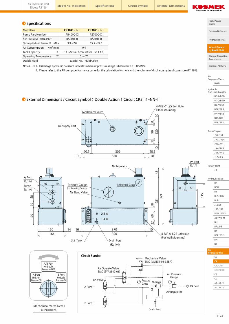
External Dimensions / Circuit Symbol:Double Action 1 Circuit CK3□1-NN-□
Circuit Symbol
MPaNm3/min
ℓ℃
Model No.Pump Part NumberNon-Leak Valve Part NumberDischarge Hydraulic Pressure ※1
Air ConsumptionTank CapacityOperating TemperatureUsable Fluid
CK3B41-□-□ CK3B71-□-□ AB4000-□ AB7000-□ BA2011-0 BA5011-0 3.9~7.0 15.5~27.0 0.4 3ℓ (Actual Amount for Use 1.4ℓ) 0 ~ 70 Model No. : Fluid Code
Model No. Indication
1
1 2 4 53
Tank Capacity
3 : 3ℓ (Actual Amount for Use 1.4ℓ)
CK 3 B4 1 - NN - 0
3 Design No.
1 : Revision Number
2 Pump Part Number (Pump Pressure Code)
B4 : AB4000-□
B7 : AB7000-□
4 Circuit Symbol
NN : Double Action 1 Circuit (Mechanical Valve at the Position of 3, 1 Piece)
A : Single Action 1 Circuit (Mechanical Valve at the Position of 2, 1 Piece)
AA : Single Action 2 Circuit (Mechanical Valve at the Position of 2, 2 Pieces)
5 Usable Fluid
0 : General Hydraulic Oil (See Hydraulic Fluid List P.1237)
S : Silicon Oil
G : Water-Glycol※ For fluids other than those described in the fluid code, please contact us.
H 2.8 ℓ
L 1.4 ℓ
A/B PortHydraulicPressure OFF
A PortHydraulicPressure ON
B PortHydraulicPressure ON
Mechanical Valve Detail(3 Positions)
Mechanical ValveSMC (VM151-01-35BA)
Air Operate ValveSMC (SYA3540-01)
PA Port
Pressure Gauge
Air Regulator
Air PressureGauge
Drain Port
B Port
AB Pump
A Port
BA Valve
Air Pressure Gauge
Air Bleed Valve
Pressure Gauge(For Incoming Pressure)
A
B
39037010
Drain Port(Rc1/4)
5039
100
164150 14
6486
A PortRc1/4
3ℓ Tank
B PortRc1/4
329
281
1860
22
104-M8×1.25 Bolt Hole(For Wall Mounting)
Air Regulator
130
3090
3010
10
309370
20.510
60.510
4-M8×1.25 Bolt Hole(Floor Mounting)
Oil Supply Port
Mechanical Valve
48
145
6684
PA PortRc1/4
Notes : ※1. Discharge hydraulic pressure indicates when air pressure range is between 0.3 ~ 0.5MPa. 1. Please refer to the AB pump performance curve for the calculation formula and the volume of discharge hydraulic pressure (P.1195).
Note : 1. Offering options with handle or with air filter. Please contact us for further information. Please note that the handle and air filter as option are not available together.
1173
AirSequence Valve
BWD
HydraulicNon-Leak Coupler
BGA/BGB
BGC/BGD
BGP/BGS
BBP/BBS
BNP/BNS
BJP/BJS
BFP/BFS
Auto Coupler
JVC/JVD
JVA/JVB
JVE/JVF
JNA/JNB
JNC/JND
JLP/JLS
Hydraulic Valve
BK
BEQ
BT
BLS/BLG
BLB
JSS/JS
JKA/JKB
AU/AU-M
BU
AirHydraulic Unit
CV
Rotary Joint
JR
BP/JPB
BX
BEP/BSP
BH
BC
Pneumatic Series
Hydraulic Series
Valve / CouplerHydraulic Unit
Cautions / Others
High-PowerSeries
Manual OperationAccessories
AirSequence Valve
BWD
HydraulicNon-Leak Coupler
BGA/BGB
BGC/BGD
BGP/BGS
BBP/BBS
BNP/BNS
BJP/BJS
BFP/BFS
Auto Coupler
JVC/JVD
JVA/JVB
JVE/JVF
JNA/JNB
JNC/JND
JLP/JLS
Hydraulic Valve
BK
BEQ
BT
BLS/BLG
BLB
JSS/JS
JKA/JKB
BMA/BMG
AU/AU-M
BU
AirHydraulic Unit
CV
CK
CP/CPB
CPC/CQC
CB
CC
AB/AB-V
AC/AC-V
Rotary Joint
JR
BP/JPB
BX
BEP/BSP
BH
BC
Pneumatic Series
Hydraulic Series
Valve / CouplerHydraulic Unit
Cautions / Others
High-PowerSeries
Manual OperationAccessories
Air Hydraulic Unit Hydraulic Unit (For Double/Single Action) model CKAir Hydraulic UnitDigest P.1169 Circuit Symbol External DimensionsModel No. Indication Specifications
Model CK
Hydraulic Unit(For Double/Single Action)
・Manual Control for Double Action/Single Action
・With Non-Leak Valve (Hydraulic pressure is held, even after air supply is cut off.)
・Portable
Features
Specifications
External Dimensions / Circuit Symbol:Double Action 1 Circuit CK3□1-NN-□
Circuit Symbol
MPaNm3/min
ℓ℃
Model No.Pump Part NumberNon-Leak Valve Part NumberDischarge Hydraulic Pressure ※1
Air ConsumptionTank CapacityOperating TemperatureUsable Fluid
CK3B41-□-□ CK3B71-□-□ AB4000-□ AB7000-□ BA2011-0 BA5011-0 3.9~7.0 15.5~27.0 0.4 3ℓ (Actual Amount for Use 1.4ℓ) 0 ~ 70 Model No. : Fluid Code
Model No. Indication
1
1 2 4 53
Tank Capacity
3 : 3ℓ (Actual Amount for Use 1.4ℓ)
CK 3 B4 1 - NN - 0
3 Design No.
1 : Revision Number
2 Pump Part Number (Pump Pressure Code)
B4 : AB4000-□
B7 : AB7000-□
4 Circuit Symbol
NN : Double Action 1 Circuit (Mechanical Valve at the Position of 3, 1 Piece)
A : Single Action 1 Circuit (Mechanical Valve at the Position of 2, 1 Piece)
AA : Single Action 2 Circuit (Mechanical Valve at the Position of 2, 2 Pieces)
5 Usable Fluid
0 : General Hydraulic Oil (See Hydraulic Fluid List P.1237)
S : Silicon Oil
G : Water-Glycol※ For fluids other than those described in the fluid code, please contact us.
H 2.8 ℓ
L 1.4 ℓ
A/B PortHydraulicPressure OFF
A PortHydraulicPressure ON
B PortHydraulicPressure ON
Mechanical Valve Detail(3 Positions)
Mechanical ValveSMC (VM151-01-35BA)
Air Operate ValveSMC (SYA3540-01)
PA Port
Pressure Gauge
Air Regulator
Air PressureGauge
Drain Port
B Port
AB Pump
A Port
BA Valve
Air Pressure Gauge
Air Bleed Valve
Pressure Gauge(For Incoming Pressure)
A
B
39037010
Drain Port(Rc1/4)
5039
100
164150 14
6486
A PortRc1/4
3ℓ Tank
B PortRc1/4
329
281
1860
22
104-M8×1.25 Bolt Hole(For Wall Mounting)
Air Regulator
130
3090
3010
10309
37020.510
60.510
4-M8×1.25 Bolt Hole(Floor Mounting)
Oil Supply Port
Mechanical Valve
48
145
6684
PA PortRc1/4
Notes : ※1. Discharge hydraulic pressure indicates when air pressure range is between 0.3 ~ 0.5MPa. 1. Please refer to the AB pump performance curve for the calculation formula and the volume of discharge hydraulic pressure (P.1195).
Note : 1. Offering options with handle or with air filter. Please contact us for further information. Please note that the handle and air filter as option are not available together.
1174

AirSequence Valve
BWD
HydraulicNon-Leak Coupler
BGA/BGB
BGC/BGD
BGP/BGS
BBP/BBS
BNP/BNS
BJP/BJS
BFP/BFS
Auto Coupler
JVC/JVD
JVA/JVB
JVE/JVF
JNA/JNB
JNC/JND
JLP/JLS
Hydraulic Valve
BK
BEQ
BT
BLS/BLG
BLB
JSS/JS
JKA/JKB
AU/AU-M
BU
AirHydraulic Unit
CV
Rotary Joint
JR
BP/JPB
BX
BEP/BSP
BH
BC
Pneumatic Series
Hydraulic Series
Valve / CouplerHydraulic Unit
Cautions / Others
High-PowerSeries
Manual OperationAccessories
AirSequence Valve
BWD
HydraulicNon-Leak Coupler
BGA/BGB
BGC/BGD
BGP/BGS
BBP/BBS
BNP/BNS
BJP/BJS
BFP/BFS
Auto Coupler
JVC/JVD
JVA/JVB
JVE/JVF
JNA/JNB
JNC/JND
JLP/JLS
Hydraulic Valve
BK
BEQ
BT
BLS/BLG
BLB
JSS/JS
JKA/JKB
BMA/BMG
AU/AU-M
BU
AirHydraulic Unit
CV
CK
CP/CPB
CPC/CQC
CB
CC
AB/AB-V
AC/AC-V
Rotary Joint
JR
BP/JPB
BX
BEP/BSP
BH
BC
Pneumatic Series
Hydraulic Series
Valve / CouplerHydraulic Unit
Cautions / Others
High-PowerSeries
Manual OperationAccessories
Air Hydraulic Unit Hydraulic Unit (For Double/Single Action) model CKAir Hydraulic UnitDigest P.1169 Circuit Symbol External DimensionsModel No. Indication Specifications
A□ PortHydraulicPressure ON
A□ PortHydraulicPressure OFF
Mechanical Valve Detail(2 Positions)
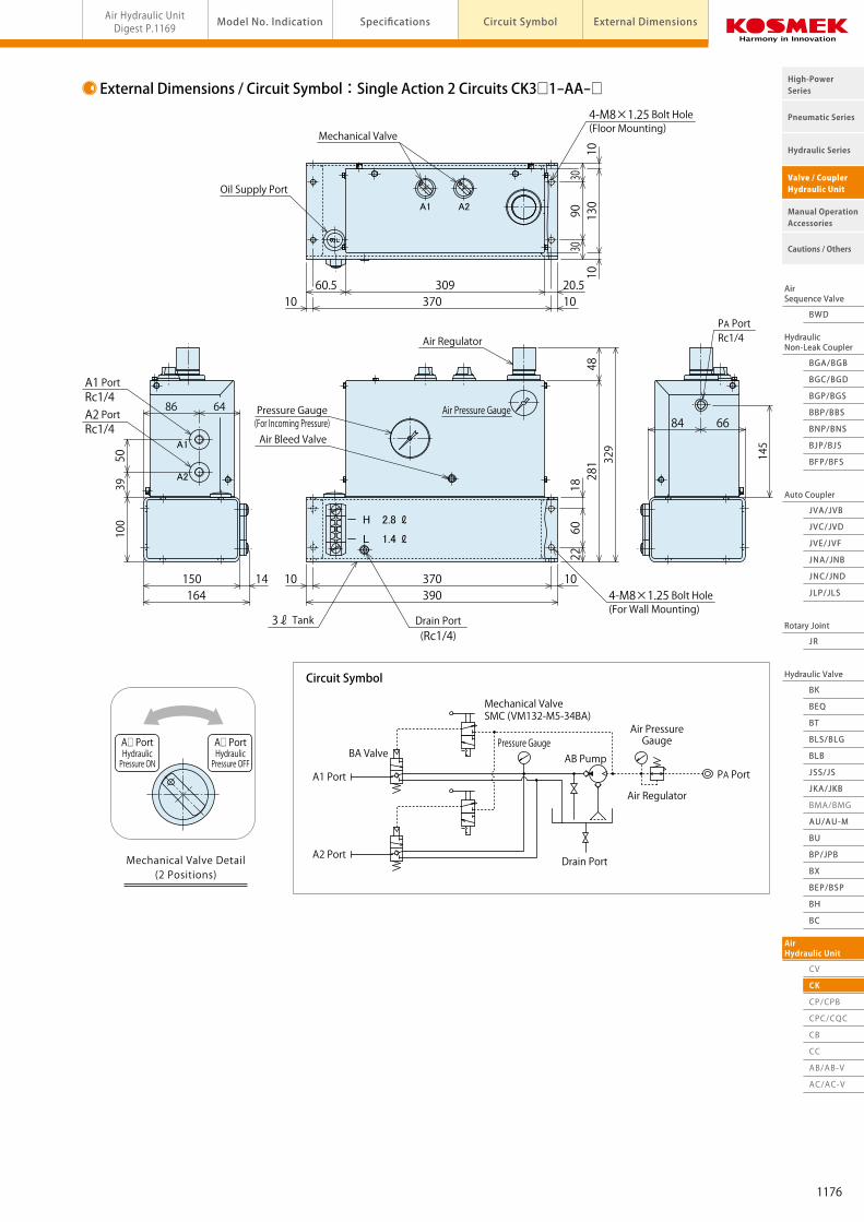
External Dimensions / Circuit Symbol:Single Action 2 Circuits CK3□1-AA-□
Circuit Symbol
External Dimensions / Circuit Symbol:Single Action 1 Circuit CK3□1-A-□
Circuit Symbol
Mechanical ValveSMC (VM132-M5-34BA)
Air Regulator
PA Port
Pressure GaugeAir PressureGauge
Drain Port
BA Valve
A1 Port
A2 Port
AB Pump
Mechanical ValveSMC (VM132-M5-34BA)
Air Regulator
PA Port
Pressure GaugeAir PressureGauge
Drain Port
BA Valve
A Port
AB Pump
A PortHydraulicPressure ON
A PortHydraulicPressure OFF
Mechanical Valve Detail(2 Positions)
H 2.8 ℓ
L 1.4 ℓ
H 2.8 ℓ
L 1.4 ℓ
130
3090
3010
10
309370
20.510
60.510
Oil Supply Port
Mechanical Valve
Air Pressure Gauge
14
39100
164150
6486
A PortRc1/4
A
48329
281
1860
2210
39037010
Air Regulator
Air Bleed Valve
Drain Port(Rc1/4)
Pressure Gauge(For Incoming Pressure)
3ℓ Tank
A2A1
A1
A2
Air Pressure Gauge
130
3090
3010
10
309370
20.510
60.510
Oil Supply Port
Mechanical Valve
48329
281
1860
22
1039037010
Air Regulator
Air Bleed Valve
Drain Port(Rc1/4)
Pressure Gauge(For Incoming Pressure)
5039
100
164150 14
6486
A1 PortRc1/4
3ℓ Tank
A2 PortRc1/4
145
6684
PA PortRc1/4
145
6684
PA PortRc1/4
4-M8×1.25 Bolt Hole(Floor Mounting)
4-M8×1.25 Bolt Hole(For Wall Mounting)
4-M8×1.25 Bolt Hole(Floor Mounting)
4-M8×1.25 Bolt Hole(For Wall Mounting)
1175
AirSequence Valve
BWD
HydraulicNon-Leak Coupler
BGA/BGB
BGC/BGD
BGP/BGS
BBP/BBS
BNP/BNS
BJP/BJS
BFP/BFS
Auto Coupler
JVC/JVD
JVA/JVB
JVE/JVF
JNA/JNB
JNC/JND
JLP/JLS
Hydraulic Valve
BK
BEQ
BT
BLS/BLG
BLB
JSS/JS
JKA/JKB
AU/AU-M
BU
AirHydraulic Unit
CV
Rotary Joint
JR
BP/JPB
BX
BEP/BSP
BH
BC
Pneumatic Series
Hydraulic Series
Valve / CouplerHydraulic Unit
Cautions / Others
High-PowerSeries
Manual OperationAccessories
AirSequence Valve
BWD
HydraulicNon-Leak Coupler
BGA/BGB
BGC/BGD
BGP/BGS
BBP/BBS
BNP/BNS
BJP/BJS
BFP/BFS
Auto Coupler
JVC/JVD
JVA/JVB
JVE/JVF
JNA/JNB
JNC/JND
JLP/JLS
Hydraulic Valve
BK
BEQ
BT
BLS/BLG
BLB
JSS/JS
JKA/JKB
BMA/BMG
AU/AU-M
BU
AirHydraulic Unit
CV
CK
CP/CPB
CPC/CQC
CB
CC
AB/AB-V
AC/AC-V
Rotary Joint
JR
BP/JPB
BX
BEP/BSP
BH
BC
Pneumatic Series
Hydraulic Series
Valve / CouplerHydraulic Unit
Cautions / Others
High-PowerSeries
Manual OperationAccessories
Air Hydraulic Unit Hydraulic Unit (For Double/Single Action) model CKAir Hydraulic UnitDigest P.1169 Circuit Symbol External DimensionsModel No. Indication Specifications
A□ PortHydraulicPressure ON
A□ PortHydraulicPressure OFF
Mechanical Valve Detail(2 Positions)
External Dimensions / Circuit Symbol:Single Action 2 Circuits CK3□1-AA-□
Circuit Symbol
External Dimensions / Circuit Symbol:Single Action 1 Circuit CK3□1-A-□
Circuit Symbol
Mechanical ValveSMC (VM132-M5-34BA)
Air Regulator
PA Port
Pressure GaugeAir PressureGauge
Drain Port
BA Valve
A1 Port
A2 Port
AB Pump
Mechanical ValveSMC (VM132-M5-34BA)
Air Regulator
PA Port
Pressure GaugeAir PressureGauge
Drain Port
BA Valve
A Port
AB Pump
A PortHydraulicPressure ON
A PortHydraulicPressure OFF
Mechanical Valve Detail(2 Positions)
H 2.8 ℓ
L 1.4 ℓ
H 2.8 ℓ
L 1.4 ℓ
130
3090
3010
10
309370
20.510
60.510
Oil Supply Port
Mechanical Valve
Air Pressure Gauge
14
39100
164150
6486
A PortRc1/4
A
48329
281
1860
22
1039037010
Air Regulator
Air Bleed Valve
Drain Port(Rc1/4)
Pressure Gauge(For Incoming Pressure)
3ℓ Tank
A2A1
A1
A2
Air Pressure Gauge
130
3090
3010
10
309370
20.510
60.510
Oil Supply Port
Mechanical Valve
48329
281
1860
2210
39037010
Air Regulator
Air Bleed Valve
Drain Port(Rc1/4)
Pressure Gauge(For Incoming Pressure)
5039
100
164150 14
6486
A1 PortRc1/4
3ℓ Tank
A2 PortRc1/4
145
6684
PA PortRc1/4
145
6684
PA PortRc1/4
4-M8×1.25 Bolt Hole(Floor Mounting)
4-M8×1.25 Bolt Hole(For Wall Mounting)
4-M8×1.25 Bolt Hole(Floor Mounting)
4-M8×1.25 Bolt Hole(For Wall Mounting)
1176

AirSequence Valve
BWD
HydraulicNon-Leak Coupler
BGA/BGB
BGC/BGD
BGP/BGS
BBP/BBS
BNP/BNS
BJP/BJS
BFP/BFS
Auto Coupler
JVC/JVD
JVA/JVB
JVE/JVF
JNA/JNB
JNC/JND
JLP/JLS
Hydraulic Valve
BK
BEQ
BT
BLS/BLG
BLB
JSS/JS
JKA/JKB
BMA/BMG
AU/AU-M
BU
AirHydraulic Unit
CV
Rotary Joint
JR
BP/JPB
BX
BEP/BSP
BH
BC
Pneumatic Series
Hydraulic Series
Valve / CouplerHydraulic Unit
Cautions / Others
High-PowerSeries
Manual OperationAccessories
AirHydraulic Unit
CV
CK
CP/CPB
CPC/CQC
CB
CC
AB/AB-V
AC/AC-V
Pneumatic Series
Hydraulic Series
Valve / CouplerHydraulic Unit
Cautions / Others
High-PowerSeries
Manual OperationAccessories
model CPAir Hydraulic Unit Hydraulic Unit (For Double/Single Action) AB Pump ModelAir Hydraulic UnitDigest P.1169 Circuit Symbol External DimensionsModel No. Indication Specifications
Model CP
・Electrical Control for Double Action/Single Action
・With Non-Leak Valve (Hydraulic pressure is held, even after air supply is cut off.)
・Compact with AB Pump Installed ・Tank Capacity 2ℓ
1
2 4 71 5 6 8 93
※ Please refer to Model CPB for 5ℓ Tank.
2 : 2ℓ (Actual Amount for Use 1.1ℓ)
CP 2 04 1 - YYYY - 5 0 - (7.0MPa)
3
2
03 : AB3000-□
04 : AB4000-□
05 : AB5000-□
06 : AB6000-□
07 : AB7000-□
08 : AB8000-□
5
1 : AC100V
2 : AC200V
3 : AC110V
4 : AC220V
5 : DC 24V
4
6
7
8
9
Hydraulic Unit(For Double/Single Action)
Features
Model No. Indication
Pump Part Number (Pump Pressure Code)
Tank Capacity
Design No.
1 : Revision Number
Circuit Symbol
NN : Double Solenoid Valve Control for Double Action Circuit
YY : Double Solenoid Valve Control for Double Action Circuit (With JBA Pressure Switch)
A : Single Solenoid Valve Control for Single Action Circuit
C : Single Solenoid Valve Control for Single Action Circuit (With JBA Pressure Switch)
U : Double Solenoid Valve Control for Single Action Circuit (With JBA Pressure Switch)
※Please contact us for other circuits.
Entry Example Double Action One Circuit (with JBA)×2 → YYYY Single Action One Circuit/Single Solenoid Valve×2 → AA
Control Voltage
Fluid Code
0 : General Hydraulic Oil (See Hydraulic Fluid List P.1237)
S : Silicon Oil
G : Water・Glycol (Iron Tank)※ For fluids other than those described in the fluid code, please contact us.
Option
Blank : Standard
H : With Piping Block
G : With a Main Pressure Gauge
Unit of Pressure Gauge
Blank : MPa (Standard)
P : PSI
Operating Pressure
Please indicate operating pressure with the unit of measurement. (Please inform us with proper unit symbols.)
Entry Example At 5.5MPa → (5.5MPa) At 25MPa → (25.0MPa) At 700PSI → (700PSI)
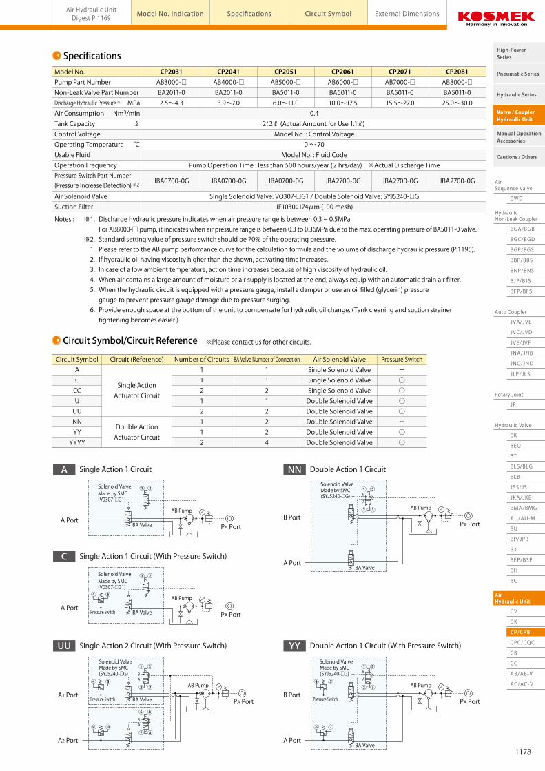
Specifications
MPaNm3/min
ℓ
℃
Model No.Pump Part NumberNon-Leak Valve Part NumberDischarge Hydraulic Pressure ※1
Air ConsumptionTank CapacityControl VoltageOperating TemperatureUsable FluidOperation FrequencyPressure Switch Part Number (Pressure Increase Detection) ※2
Air Solenoid ValveSuction Filter
CP2031 CP2041 CP2051 CP2061 CP2071 CP2081 AB3000-□ AB4000-□ AB5000-□ AB6000-□ AB7000-□ AB8000-□ BA2011-0 BA2011-0 BA5011-0 BA5011-0 BA5011-0 BA5011-0 2.5~4.3 3.9~7.0 6.0~11.0 10.0~17.5 15.5~27.0 25.0~30.0 0.4 2:2ℓ (Actual Amount for Use 1.1ℓ) Model No. : Control Voltage 0 ~ 70 Model No. : Fluid Code Pump Operation Time : less than 500 hours/year (2 hrs/day) ※Actual Discharge Time
JBA0700-0G JBA0700-0G JBA0700-0G JBA2700-0G JBA2700-0G JBA2700-0G
Single Solenoid Valve: VO307-□G1 / Double Solenoid Valve: SYJ5240-□G JF1030:174μm (100 mesh)
Notes : ※1. Discharge hydraulic pressure indicates when air pressure range is between 0.3 ~ 0.5MPa. For AB8000-□ pump, it indicates when air pressure range is between 0.3 to 0.36MPa due to the max. operating pressure of BA5011-0 valve. ※2. Standard setting value of pressure switch should be 70% of the operating pressure. 1. Please refer to the AB pump performance curve for the calculation formula and the volume of discharge hydraulic pressure (P.1195). 2. If hydraulic oil having viscosity higher than the shown, activating time increases. 3. In case of a low ambient temperature, action time increases because of high viscosity of hydraulic oil. 4. When air contains a large amount of moisture or air supply is located at the end, always equip with an automatic drain air filter. 5. When the hydraulic circuit is equipped with a pressure gauge, install a damper or use an oil filled (glycerin) pressure gauge to prevent pressure gauge damage due to pressure surging. 6. Provide enough space at the bottom of the unit to compensate for hydraulic oil change. (Tank cleaning and suction strainer tightening becomes easier.)
Circuit Symbol/Circuit Reference
Circuit SymbolACCCUUUNNYYYYYY
Circuit (Reference)
Single ActionActuator Circuit
Double ActionActuator Circuit
Number of Circuits11212112
BA Valve Number of Connection11212224
Pressure Switch-○○○○-○○
Air Solenoid ValveSingle Solenoid ValveSingle Solenoid ValveSingle Solenoid ValveDouble Solenoid ValveDouble Solenoid ValveDouble Solenoid ValveDouble Solenoid ValveDouble Solenoid Valve
※Please contact us for other circuits.
PA PortA Port
AB Pump
Solenoid Valve
BA Valve
① ②Made by SMC (V0307-□G1)
A PortAB Pump
Solenoid Valve
BA ValvePressure Switch
① ②Made by SMC (V0307-□G1)
A1 Port
A2 Port
AB Pump
Solenoid Valve
BA ValvePressure Switch
① ③
② ③
Made by SMC (SYJ5240-□G) B
A
⑥ ⑧
⑦ ⑧
BA
B Port
A Port
AB Pump
Solenoid Valve
Pressure Switch
① ③
② ③
Made by SMC (SYJ5240-□G) B
A
BA Valve
B Port
A Port
AB Pump
Solenoid Valve① ③
② ③
Made by SMC (SYJ5240-□G) B
A
BA Valve
Double Action 1 Circuit (With Pressure Switch)YYSingle Action 2 Circuit (With Pressure Switch)UU
Single Action 1 Circuit (With Pressure Switch)C
Double Action 1 CircuitNNSingle Action 1 CircuitA
PA Port
PA Port
PA Port
PA Port
④ ⑤
④ ⑤
⑨ ⑩
④ ⑤
⑥ ⑦
1177
AirSequence Valve
BWD
HydraulicNon-Leak Coupler
BGA/BGB
BGC/BGD
BGP/BGS
BBP/BBS
BNP/BNS
BJP/BJS
BFP/BFS
Auto Coupler
JVC/JVD
JVA/JVB
JVE/JVF
JNA/JNB
JNC/JND
JLP/JLS
Hydraulic Valve
BK
BEQ
BT
BLS/BLG
BLB
JSS/JS
JKA/JKB
BMA/BMG
AU/AU-M
BU
AirHydraulic Unit
CV
Rotary Joint
JR
BP/JPB
BX
BEP/BSP
BH
BC
Pneumatic Series
Hydraulic Series
Valve / CouplerHydraulic Unit
Cautions / Others
High-PowerSeries
Manual OperationAccessories
AirHydraulic Unit
CV
CK
CP/CPB
CPC/CQC
CB
CC
AB/AB-V
AC/AC-V
Pneumatic Series
Hydraulic Series
Valve / CouplerHydraulic Unit
Cautions / Others
High-PowerSeries
Manual OperationAccessories
model CPAir Hydraulic Unit Hydraulic Unit (For Double/Single Action) AB Pump ModelAir Hydraulic UnitDigest P.1169 Circuit Symbol External DimensionsModel No. Indication Specifications
Model CP
・Electrical Control for Double Action/Single Action
・With Non-Leak Valve (Hydraulic pressure is held, even after air supply is cut off.)
・Compact with AB Pump Installed ・Tank Capacity 2ℓ
1
2 4 71 5 6 8 93
※ Please refer to Model CPB for 5ℓ Tank.
2 : 2ℓ (Actual Amount for Use 1.1ℓ)
CP 2 04 1 - YYYY - 5 0 - (7.0MPa)
3
2
03 : AB3000-□
04 : AB4000-□
05 : AB5000-□
06 : AB6000-□
07 : AB7000-□
08 : AB8000-□
5
1 : AC100V
2 : AC200V
3 : AC110V
4 : AC220V
5 : DC 24V
4
6
7
8
9
Hydraulic Unit(For Double/Single Action)
Features
Model No. Indication
Pump Part Number (Pump Pressure Code)
Tank Capacity
Design No.
1 : Revision Number
Circuit Symbol
NN : Double Solenoid Valve Control for Double Action Circuit
YY : Double Solenoid Valve Control for Double Action Circuit (With JBA Pressure Switch)
A : Single Solenoid Valve Control for Single Action Circuit
C : Single Solenoid Valve Control for Single Action Circuit (With JBA Pressure Switch)
U : Double Solenoid Valve Control for Single Action Circuit (With JBA Pressure Switch)
※Please contact us for other circuits.
Entry Example Double Action One Circuit (with JBA)×2 → YYYY Single Action One Circuit/Single Solenoid Valve×2 → AA
Control Voltage
Fluid Code
0 : General Hydraulic Oil (See Hydraulic Fluid List P.1237)
S : Silicon Oil
G : Water・Glycol (Iron Tank)※ For fluids other than those described in the fluid code, please contact us.
Option
Blank : Standard
H : With Piping Block
G : With a Main Pressure Gauge
Unit of Pressure Gauge
Blank : MPa (Standard)
P : PSI
Operating Pressure
Please indicate operating pressure with the unit of measurement. (Please inform us with proper unit symbols.)
Entry Example At 5.5MPa → (5.5MPa) At 25MPa → (25.0MPa) At 700PSI → (700PSI)
Specifications
MPaNm3/min
ℓ
℃
Model No.Pump Part NumberNon-Leak Valve Part NumberDischarge Hydraulic Pressure ※1
Air ConsumptionTank CapacityControl VoltageOperating TemperatureUsable FluidOperation FrequencyPressure Switch Part Number (Pressure Increase Detection) ※2
Air Solenoid ValveSuction Filter
CP2031 CP2041 CP2051 CP2061 CP2071 CP2081 AB3000-□ AB4000-□ AB5000-□ AB6000-□ AB7000-□ AB8000-□ BA2011-0 BA2011-0 BA5011-0 BA5011-0 BA5011-0 BA5011-0 2.5~4.3 3.9~7.0 6.0~11.0 10.0~17.5 15.5~27.0 25.0~30.0 0.4 2:2ℓ (Actual Amount for Use 1.1ℓ) Model No. : Control Voltage 0 ~ 70 Model No. : Fluid Code Pump Operation Time : less than 500 hours/year (2 hrs/day) ※Actual Discharge Time
JBA0700-0G JBA0700-0G JBA0700-0G JBA2700-0G JBA2700-0G JBA2700-0G
Single Solenoid Valve: VO307-□G1 / Double Solenoid Valve: SYJ5240-□G JF1030:174μm (100 mesh)
Notes : ※1. Discharge hydraulic pressure indicates when air pressure range is between 0.3 ~ 0.5MPa. For AB8000-□ pump, it indicates when air pressure range is between 0.3 to 0.36MPa due to the max. operating pressure of BA5011-0 valve. ※2. Standard setting value of pressure switch should be 70% of the operating pressure. 1. Please refer to the AB pump performance curve for the calculation formula and the volume of discharge hydraulic pressure (P.1195). 2. If hydraulic oil having viscosity higher than the shown, activating time increases. 3. In case of a low ambient temperature, action time increases because of high viscosity of hydraulic oil. 4. When air contains a large amount of moisture or air supply is located at the end, always equip with an automatic drain air filter. 5. When the hydraulic circuit is equipped with a pressure gauge, install a damper or use an oil filled (glycerin) pressure gauge to prevent pressure gauge damage due to pressure surging. 6. Provide enough space at the bottom of the unit to compensate for hydraulic oil change. (Tank cleaning and suction strainer tightening becomes easier.)
Circuit Symbol/Circuit Reference
Circuit SymbolACCCUUUNNYYYYYY
Circuit (Reference)
Single ActionActuator Circuit
Double ActionActuator Circuit
Number of Circuits11212112
BA Valve Number of Connection11212224
Pressure Switch-○○○○-○○
Air Solenoid ValveSingle Solenoid ValveSingle Solenoid ValveSingle Solenoid ValveDouble Solenoid ValveDouble Solenoid ValveDouble Solenoid ValveDouble Solenoid ValveDouble Solenoid Valve
※Please contact us for other circuits.
PA PortA Port
AB Pump
Solenoid Valve
BA Valve
① ②Made by SMC (V0307-□G1)
A PortAB Pump
Solenoid Valve
BA ValvePressure Switch
① ②Made by SMC (V0307-□G1)
A1 Port
A2 Port
AB Pump
Solenoid Valve
BA ValvePressure Switch
① ③
② ③
Made by SMC (SYJ5240-□G) B
A
⑥ ⑧
⑦ ⑧
BA
B Port
A Port
AB Pump
Solenoid Valve
Pressure Switch
① ③
② ③
Made by SMC (SYJ5240-□G) B
A
BA Valve
B Port
A Port
AB Pump
Solenoid Valve① ③
② ③
Made by SMC (SYJ5240-□G) B
A
BA Valve
Double Action 1 Circuit (With Pressure Switch)YYSingle Action 2 Circuit (With Pressure Switch)UU
Single Action 1 Circuit (With Pressure Switch)C
Double Action 1 CircuitNNSingle Action 1 CircuitA
PA Port
PA Port
PA Port
PA Port
④ ⑤
④ ⑤
⑨ ⑩
④ ⑤
⑥ ⑦
1178
AirSequence Valve
BWD
HydraulicNon-Leak Coupler
BGA/BGB
BGC/BGD
BGP/BGS
BBP/BBS
BNP/BNS
BJP/BJS
BFP/BFS
Auto Coupler
JVC/JVD
JVA/JVB
JVE/JVF
JNA/JNB
JNC/JND
JLP/JLS
Hydraulic Valve
BK
BEQ
BT
BLS/BLG
BLB
JSS/JS
JKA/JKB
BMA/BMG
AU/AU-M
BU
AirHydraulic Unit
CV
Rotary Joint
JR
BP/JPB
BX
BEP/BSP
BH
BC
Pneumatic Series
Hydraulic Series
Valve / CouplerHydraulic Unit
Cautions / Others
High-PowerSeries
Manual OperationAccessories
AirHydraulic Unit
CV
CK
CP/CPB
CPC/CQC
CB
CC
AB/AB-V
AC/AC-V
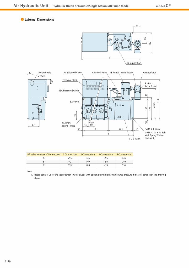
Air Hydraulic Unit Hydraulic Unit (For Double/Single Action) AB Pump Model model CPAir Hydraulic UnitDigest P.1169 Circuit Symbol External DimensionsModel No. Indication Specifications
External Dimensions
Note 1. Please contact us for the specification (water-glycol, with option piping block, with source pressure indicator) other than the drawing above.
BA Valve Number of ConnectionABC
1 Connection 2 Connections 3 Connections 4 Connections 295 345 395 445 90 140 190 240 359 409 459 510
55
C
Oil Supply Port
85
157
H 1.4
L 0.3
Air Solenoid Valve
JBA Pressure Switch
2-φ2830 Conduit Hole
BA Valve
Air Bleed Valve AB Pump Air Pressure Gauge Air Regulator
6-M8 Bolt Hole
Terminal Block
310
239.5
170
150
70
1010
10185
2ℓ Tank
B
A
10
87
34.2
45
PA PortRc1/4 Thread
6-M8×1.25×16 BoltWith Spring Washer (Included)
n-A PortRc1/4 Thread
Distance50
MEMO
1179

AirSequence Valve
BWD
HydraulicNon-Leak Coupler
BGA/BGB
BGC/BGD
BGP/BGS
BBP/BBS
BNP/BNS
BJP/BJS
BFP/BFS
Auto Coupler
JVC/JVD
JVA/JVB
JVE/JVF
JNA/JNB
JNC/JND
JLP/JLS
Hydraulic Valve
BK
BEQ
BT
BLS/BLG
BLB
JSS/JS
JKA/JKB
BMA/BMG
AU/AU-M
BU
AirHydraulic Unit
CV
Rotary Joint
JR
BP/JPB
BX
BEP/BSP
BH
BC
Pneumatic Series
Hydraulic Series
Valve / CouplerHydraulic Unit
Cautions / Others
High-PowerSeries
Manual OperationAccessories
AirHydraulic Unit
CV
CK
CP/CPB
CPC/CQC
CB
CC
AB/AB-V
AC/AC-V
Air Hydraulic Unit Hydraulic Unit (For Double/Single Action) AB Pump Model model CPAir Hydraulic UnitDigest P.1169 Circuit Symbol External DimensionsModel No. Indication Specifications
External Dimensions
Note 1. Please contact us for the specification (water-glycol, with option piping block, with source pressure indicator) other than the drawing above.
BA Valve Number of ConnectionABC
1 Connection 2 Connections 3 Connections 4 Connections 295 345 395 445 90 140 190 240 359 409 459 510
55
C
Oil Supply Port
85
157
H 1.4
L 0.3
Air Solenoid Valve
JBA Pressure Switch
2-φ2830 Conduit Hole
BA Valve
Air Bleed Valve AB Pump Air Pressure Gauge Air Regulator
6-M8 Bolt Hole
Terminal Block
310
239.5
170
150
70
1010
10185
2ℓ Tank
B
A
10
87
34.2
45
PA PortRc1/4 Thread
6-M8×1.25×16 BoltWith Spring Washer (Included)
n-A PortRc1/4 Thread
Distance50
MEMO
1180

AirSequence Valve
BWD
HydraulicNon-Leak Coupler
BGA/BGB
BGC/BGD
BGP/BGS
BBP/BBS
BNP/BNS
BJP/BJS
BFP/BFS
Auto Coupler
JVC/JVD
JVA/JVB
JVE/JVF
JNA/JNB
JNC/JND
JLP/JLS
Hydraulic Valve
BK
BEQ
BT
BLS/BLG
BLB
JSS/JS
JKA/JKB
BMA/BMG
AU/AU-M
BU
AirHydraulic Unit
CV
Rotary Joint
JR
BP/JPB
BX
BEP/BSP
BH
BC
Pneumatic Series
Hydraulic Series
Valve / CouplerHydraulic Unit
Cautions / Others
High-PowerSeries
Manual OperationAccessories
AirHydraulic Unit
CV
CK
CP/CPB
CPC/CQC
CB
CC
AB/AB-V
AC/AC-V
Pneumatic Series
Hydraulic Series
Valve / CouplerHydraulic Unit
Cautions / Others
High-PowerSeries
Manual OperationAccessories
model CPBAir Hydraulic Unit Hydraulic Unit (For Double/Single Action) AB Pump ModelAir Hydraulic UnitDigest P.1169 Circuit Symbol External DimensionsModel No. Indication Specifications
Model CPB
Model No. Indication
1 Tank Capacity
※ Please refer to Model CP for 2ℓ Tank.
P : 5ℓ (Actual Amount for Use 3.7ℓ)
4 Design No.
0 : Revision Number
2 Pump Part Number (Pump Pressure Code)
3 : AB3000-□ 4 : AB4000-□ 5 : AB5000-□
6 : AB6000-□ 7 : AB7000-□ 8 : AB8000-□
6 Control Voltage
1 : AC100V 2 : AC200V 3 : AC110V
4 : AC220V 5 : DC 24V
5 Circuit Symbol (Indicate with the number of circuits and circuit symbol.)
NN : Double Solenoid Valve Control for Double Action CircuitYY : Double Solenoid Valve Control for Double Action Circuit (With JBA Pressure Switch)E : Single Solenoid Valve Control for Single Action CircuitG : Single Solenoid Valve Control for Single Action Circuit (With JBA Pressure Switch)U : Double Solenoid Valve Control for Single Action Circuit (With JBA Pressure Switch)
7 Option
Blank : Standard C : +Common D : Digital Pressure Sensor E : Without Filter Regulator F : Manual-Drain Filter Regulator G : With Primary Pressure Gauge H : With Piping Block on the Left J : With Air Regulator K0 : With Pressure Gauge for Each Circuit (Without Primary Pressure Gauge) K1 : With Color Displayed Pressure Gauge for Each Circuit (Without Primary Pressure Gauge) KG0 : With Pressure Gauge for Each Circuit (With Primary Pressure Gauge) KG1 : With Color Displayed Pressure Gauge for Each Circuit (With Primary Pressure Gauge) L : With Pressure Switch Light N : Piping Port NPT Thread, Pressure Gauge in both PSI/MPa ※1
P : Pressure Gauge in both PSI/MPa Q0 : With Oil Level Switch (ON when Oil Level Drops) Q1 : With Oil Level Switch (OFF when Oil Level Drops) T : Iron Tank
8 Operating Pressure
Please indicate operating pressure with the unit of measurement. (Please inform us with proper unit symbols.)
3 Fluid Code
0 : General Hydraulic Oil (See Hydraulic Fluid List P.1237)S : Silicon OilG : Water・Glycol (Iron Tank)F : Fatty Acid Ester※ For fluids other than those described in the fluid code, please contact us.
41 2 3 6 7 85
C P B 4 0 0 0 - 2YY - 5 - (7.0MPa )
Hydraulic Unit(For Double/Single Action)
・Electrical Control for Double Action/Single Action
・With Non-Leak Valve (Hydraulic pressure is held, even after air supply is cut off.)
・Compact with AB Pump Installed ・Tank Capacity 5ℓ
Features
※Please contact us for other circuits.
Entry Example Double Action One Circuit (with JBA)×2 → 2YY Single Action One Circuit/Single Solenoid Valve×2 → 2E
Entry Example At 5.5MPa → (5.5MPa) At 25MPa → (25.0MPa) At 700PSI → (700PSI)
Notes: ※1. When selecting Option N:Piping Port NPT Thread, dimensions in the specification sheet and other documents are in inches. 1. Please contact us for specifications and external dimensions for options.
7
A PortAB Pump
Solenoid Valve
BA Valve
Made by SMC (SYJ3140-□G)
A PortAB Pump
Solenoid Valve
BA ValvePressure Switch
Made by SMC (SYJ3140-□G)
A1 Port
A2 Port
AB Pump
Solenoid Valve
BA ValvePressure Switch
① ③
② ③
Made by SMC (SYJ3240-□G) B
A
⑥ ⑧
⑦ ⑧
BA
B Port
A Port
AB Pump
Solenoid Valve
Pressure Switch
① ③
② ③
Made by SMC (SYJ3240-□G) B
A
BA Valve
B Port
A Port
AB Pump
Solenoid Valve① ③
② ③
Made by SMC (SYJ3240-□G) B
A
BA Valve
Double Action 1 Circuit (With Pressure Switch)YYSingle Action 2 Circuit (With Pressure Switch)UU
Single Action 1 Circuit (With Pressure Switch)G
Double Action 1 CircuitNNSingle Action 1 CircuitE
PA Port
④ ⑤
④ ⑤
⑨ ⑩
④ ⑤
⑥ ⑦
PA Port
PA Port
PA Port
PA Port
① ②
AB
① ②
AB
Specifications
MPaNm3/min
ℓ
℃
Model No.Pump Part NumberNon-Leak Valve Part NumberDischarge Hydraulic Pressure ※1
Air ConsumptionTank CapacityControl VoltageOperating TemperatureUsable FluidOperation FrequencyPressure Switch Part Number (Pressure Increase Detection) ※2
Air Solenoid ValveSuction Filter
CPB30□0 CPB40□0 CPB50□0 CPB60□0 CPB70□0 CPB80□0 AB3000-□ AB4000-□ AB5000-□ AB6000-□ AB7000-□ AB8000-□ BA2011-0 BA2011-0 BA5011-0 BA5011-0 BA5011-0 BA5011-0 2.5~4.3 3.9~7.0 6.0~11.0 10.0~17.5 15.5~27.0 25.0~30.0 0.4 5:5ℓ (Actual Amount for Use 3.7ℓ) Model No. : Control Voltage 0 ~ 70 Model No. : Fluid Code Pump Operation Time : less than 500 hours/year (2 hrs/day) ※Actual Discharge Time
JBA0700-0G JBA0700-0G JBA0700-0G JBA2700-0G JBA2700-0G JBA2700-0G
Single Solenoid Valve: SYJ3140-□G / Double Solenoid Valve: SYJ3240-□G JF1030:174μm (100 mesh)
Notes : ※1. Discharge hydraulic pressure indicates when air pressure range is between 0.3 ~ 0.5MPa. For AB8000-□ pump, it indicates when air pressure range is between 0.3 to 0.36MPa due to the max. operating pressure of BA5011-0 valve. ※2. Standard setting value of pressure switch should be 70% of the operating pressure. 1. Please refer to the AB pump performance curve for the calculation formula and the volume of discharge hydraulic pressure (P.1195). 2. If hydraulic oil having viscosity higher than the shown, activating time increases. 3. In case of a low ambient temperature, action time increases because of high viscosity of hydraulic oil. 4. When the hydraulic circuit is equipped with a pressure gauge, install a damper or use an oil filled (glycerin) pressure gauge to prevent pressure gauge damage due to pressure surging. 5. Provide enough space at the bottom of the unit to compensate for hydraulic oil change. (Tank cleaning and suction strainer tightening becomes easier.)
Circuit Symbol/Circuit Reference
Circuit SymbolEG2GU2UNNYY2YY
Circuit (Reference)
Single ActionActuator Circuit
Double ActionActuator Circuit
Number of Circuits11212112
BA Valve Number of Connection11212224
Pressure Switch-○○○○-○○
Air Solenoid ValveSingle Solenoid ValveSingle Solenoid ValveSingle Solenoid ValveDouble Solenoid ValveDouble Solenoid ValveDouble Solenoid ValveDouble Solenoid ValveDouble Solenoid Valve
※Please contact us for other circuits.
1181

AirSequence Valve
BWD
HydraulicNon-Leak Coupler
BGA/BGB
BGC/BGD
BGP/BGS
BBP/BBS
BNP/BNS
BJP/BJS
BFP/BFS
Auto Coupler
JVC/JVD
JVA/JVB
JVE/JVF
JNA/JNB
JNC/JND
JLP/JLS
Hydraulic Valve
BK
BEQ
BT
BLS/BLG
BLB
JSS/JS
JKA/JKB
BMA/BMG
AU/AU-M
BU
AirHydraulic Unit
CV
Rotary Joint
JR
BP/JPB
BX
BEP/BSP
BH
BC
Pneumatic Series
Hydraulic Series
Valve / CouplerHydraulic Unit
Cautions / Others
High-PowerSeries
Manual OperationAccessories
AirHydraulic Unit
CV
CK
CP/CPB
CPC/CQC
CB
CC
AB/AB-V
AC/AC-V
Pneumatic Series
Hydraulic Series
Valve / CouplerHydraulic Unit
Cautions / Others
High-PowerSeries
Manual OperationAccessories
model CPBAir Hydraulic Unit Hydraulic Unit (For Double/Single Action) AB Pump ModelAir Hydraulic UnitDigest P.1169 Circuit Symbol External DimensionsModel No. Indication Specifications
Model CPB
Model No. Indication
1 Tank Capacity
※ Please refer to Model CP for 2ℓ Tank.
P : 5ℓ (Actual Amount for Use 3.7ℓ)
4 Design No.
0 : Revision Number
2 Pump Part Number (Pump Pressure Code)
3 : AB3000-□ 4 : AB4000-□ 5 : AB5000-□
6 : AB6000-□ 7 : AB7000-□ 8 : AB8000-□
6 Control Voltage
1 : AC100V 2 : AC200V 3 : AC110V
4 : AC220V 5 : DC 24V
5 Circuit Symbol (Indicate with the number of circuits and circuit symbol.)
NN : Double Solenoid Valve Control for Double Action CircuitYY : Double Solenoid Valve Control for Double Action Circuit (With JBA Pressure Switch)E : Single Solenoid Valve Control for Single Action CircuitG : Single Solenoid Valve Control for Single Action Circuit (With JBA Pressure Switch)U : Double Solenoid Valve Control for Single Action Circuit (With JBA Pressure Switch)
7 Option
Blank : Standard C : +Common D : Digital Pressure Sensor E : Without Filter Regulator F : Manual-Drain Filter Regulator G : With Primary Pressure Gauge H : With Piping Block on the Left J : With Air Regulator K0 : With Pressure Gauge for Each Circuit (Without Primary Pressure Gauge) K1 : With Color Displayed Pressure Gauge for Each Circuit (Without Primary Pressure Gauge) KG0 : With Pressure Gauge for Each Circuit (With Primary Pressure Gauge) KG1 : With Color Displayed Pressure Gauge for Each Circuit (With Primary Pressure Gauge) L : With Pressure Switch Light N : Piping Port NPT Thread, Pressure Gauge in both PSI/MPa ※1
P : Pressure Gauge in both PSI/MPa Q0 : With Oil Level Switch (ON when Oil Level Drops) Q1 : With Oil Level Switch (OFF when Oil Level Drops) T : Iron Tank
8 Operating Pressure
Please indicate operating pressure with the unit of measurement. (Please inform us with proper unit symbols.)
3 Fluid Code
0 : General Hydraulic Oil (See Hydraulic Fluid List P.1237)S : Silicon OilG : Water・Glycol (Iron Tank)F : Fatty Acid Ester※ For fluids other than those described in the fluid code, please contact us.
41 2 3 6 7 85
C P B 4 0 0 0 - 2YY - 5 - (7.0MPa )
Hydraulic Unit(For Double/Single Action)
・Electrical Control for Double Action/Single Action
・With Non-Leak Valve (Hydraulic pressure is held, even after air supply is cut off.)
・Compact with AB Pump Installed ・Tank Capacity 5ℓ
Features
※Please contact us for other circuits.
Entry Example Double Action One Circuit (with JBA)×2 → 2YY Single Action One Circuit/Single Solenoid Valve×2 → 2E
Entry Example At 5.5MPa → (5.5MPa) At 25MPa → (25.0MPa) At 700PSI → (700PSI)
Notes: ※1. When selecting Option N:Piping Port NPT Thread, dimensions in the specification sheet and other documents are in inches. 1. Please contact us for specifications and external dimensions for options.
7
A PortAB Pump
Solenoid Valve
BA Valve
Made by SMC (SYJ3140-□G)
A PortAB Pump
Solenoid Valve
BA ValvePressure Switch
Made by SMC (SYJ3140-□G)
A1 Port
A2 Port
AB Pump
Solenoid Valve
BA ValvePressure Switch
① ③
② ③
Made by SMC (SYJ3240-□G) B
A
⑥ ⑧
⑦ ⑧
BA
B Port
A Port
AB Pump
Solenoid Valve
Pressure Switch
① ③
② ③
Made by SMC (SYJ3240-□G) B
A
BA Valve
B Port
A Port
AB Pump
Solenoid Valve① ③
② ③
Made by SMC (SYJ3240-□G) B
A
BA Valve
Double Action 1 Circuit (With Pressure Switch)YYSingle Action 2 Circuit (With Pressure Switch)UU
Single Action 1 Circuit (With Pressure Switch)G
Double Action 1 CircuitNNSingle Action 1 CircuitE
PA Port
④ ⑤
④ ⑤
⑨ ⑩
④ ⑤
⑥ ⑦
PA Port
PA Port
PA Port
PA Port
① ②
AB
① ②
AB
Specifications
MPaNm3/min
ℓ
℃
Model No.Pump Part NumberNon-Leak Valve Part NumberDischarge Hydraulic Pressure ※1
Air ConsumptionTank CapacityControl VoltageOperating TemperatureUsable FluidOperation FrequencyPressure Switch Part Number (Pressure Increase Detection) ※2
Air Solenoid ValveSuction Filter
CPB30□0 CPB40□0 CPB50□0 CPB60□0 CPB70□0 CPB80□0 AB3000-□ AB4000-□ AB5000-□ AB6000-□ AB7000-□ AB8000-□ BA2011-0 BA2011-0 BA5011-0 BA5011-0 BA5011-0 BA5011-0 2.5~4.3 3.9~7.0 6.0~11.0 10.0~17.5 15.5~27.0 25.0~30.0 0.4 5:5ℓ (Actual Amount for Use 3.7ℓ) Model No. : Control Voltage 0 ~ 70 Model No. : Fluid Code Pump Operation Time : less than 500 hours/year (2 hrs/day) ※Actual Discharge Time
JBA0700-0G JBA0700-0G JBA0700-0G JBA2700-0G JBA2700-0G JBA2700-0G
Single Solenoid Valve: SYJ3140-□G / Double Solenoid Valve: SYJ3240-□G JF1030:174μm (100 mesh)
Notes : ※1. Discharge hydraulic pressure indicates when air pressure range is between 0.3 ~ 0.5MPa. For AB8000-□ pump, it indicates when air pressure range is between 0.3 to 0.36MPa due to the max. operating pressure of BA5011-0 valve. ※2. Standard setting value of pressure switch should be 70% of the operating pressure. 1. Please refer to the AB pump performance curve for the calculation formula and the volume of discharge hydraulic pressure (P.1195). 2. If hydraulic oil having viscosity higher than the shown, activating time increases. 3. In case of a low ambient temperature, action time increases because of high viscosity of hydraulic oil. 4. When the hydraulic circuit is equipped with a pressure gauge, install a damper or use an oil filled (glycerin) pressure gauge to prevent pressure gauge damage due to pressure surging. 5. Provide enough space at the bottom of the unit to compensate for hydraulic oil change. (Tank cleaning and suction strainer tightening becomes easier.)
Circuit Symbol/Circuit Reference
Circuit SymbolEG2GU2UNNYY2YY
Circuit (Reference)
Single ActionActuator Circuit
Double ActionActuator Circuit
Number of Circuits11212112
BA Valve Number of Connection11212224
Pressure Switch-○○○○-○○
Air Solenoid ValveSingle Solenoid ValveSingle Solenoid ValveSingle Solenoid ValveDouble Solenoid ValveDouble Solenoid ValveDouble Solenoid ValveDouble Solenoid ValveDouble Solenoid Valve
※Please contact us for other circuits.
1182
AirSequence Valve
BWD
HydraulicNon-Leak Coupler
BGA/BGB
BGC/BGD
BGP/BGS
BBP/BBS
BNP/BNS
BJP/BJS
BFP/BFS
Auto Coupler
JVC/JVD
JVA/JVB
JVE/JVF
JNA/JNB
JNC/JND
JLP/JLS
Hydraulic Valve
BK
BEQ
BT
BLS/BLG
BLB
JSS/JS
JKA/JKB
BMA/BMG
AU/AU-M
BU
AirHydraulic Unit
CV
Rotary Joint
JR
BP/JPB
BX
BEP/BSP
BH
BC
Pneumatic Series
Hydraulic Series
Valve / CouplerHydraulic Unit
Cautions / Others
High-PowerSeries
Manual OperationAccessories
AirHydraulic Unit
CV
CK
CP/CPB
CPC/CQC
CB
CC
AB/AB-V
AC/AC-V
Pneumatic Series
Hydraulic Series
Valve / CouplerHydraulic Unit
Cautions / Others
High-PowerSeries
Manual OperationAccessories
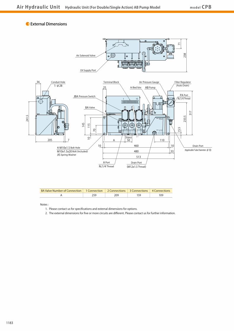
Air Hydraulic UnitDigest P.1169 Circuit Symbol External DimensionsModel No. Indication SpecificationsAir Hydraulic Unit Hydraulic Unit (For Double/Single Action) AB Pump Model model CPB
External Dimensions MEMO
Notes : 1. Please contact us for specifications and external dimensions for options. 2. The external dimensions for five or more circuits are different. Please contact us for further information.
BA Valve Number of ConnectionA
1 Connection 2 Connections 3 Connections 4 Connections 259 209 159 109
OIL
AB
A1 A2 A□
1 15
H5.0
L1.3
7
36
205
241.5
71
238
513
33480
460 10
110
10
25
50Distance
A10
145
15.5
233.5 317
115
70
Conduit Hole1-φ28
Air Solenoid Valve
Oil Supply Port
4-M10x1.5 Bolt HoleM10x1.5x20 Bolt (Included)JIS Spring Washer
JBA Pressure Switch
AB Pump
Filter Regulator(Auto Drain)
PA PortRc1/4 Thread
Air Pressure GaugeTerminal Block
Air Bleed Valve
BA Valve
A PortRc1/4 Thread
Drain Port
(M12x1.5 Thread)
Drain Port
(Applicable Tube Diameter φ10)
1183
AirSequence Valve
BWD
HydraulicNon-Leak Coupler
BGA/BGB
BGC/BGD
BGP/BGS
BBP/BBS
BNP/BNS
BJP/BJS
BFP/BFS
Auto Coupler
JVC/JVD
JVA/JVB
JVE/JVF
JNA/JNB
JNC/JND
JLP/JLS
Hydraulic Valve
BK
BEQ
BT
BLS/BLG
BLB
JSS/JS
JKA/JKB
BMA/BMG
AU/AU-M
BU
AirHydraulic Unit
CV
Rotary Joint
JR
BP/JPB
BX
BEP/BSP
BH
BC
Pneumatic Series
Hydraulic Series
Valve / CouplerHydraulic Unit
Cautions / Others
High-PowerSeries
Manual OperationAccessories
AirHydraulic Unit
CV
CK
CP/CPB
CPC/CQC
CB
CC
AB/AB-V
AC/AC-V
Pneumatic Series
Hydraulic Series
Valve / CouplerHydraulic Unit
Cautions / Others
High-PowerSeries
Manual OperationAccessories
Air Hydraulic UnitDigest P.1169 Circuit Symbol External DimensionsModel No. Indication SpecificationsAir Hydraulic Unit Hydraulic Unit (For Double/Single Action) AB Pump Model model CPB
External Dimensions MEMO
Notes : 1. Please contact us for specifications and external dimensions for options. 2. The external dimensions for five or more circuits are different. Please contact us for further information.
BA Valve Number of ConnectionA
1 Connection 2 Connections 3 Connections 4 Connections 259 209 159 109
OIL
AB
A1 A2 A□
1 15
H5.0
L1.3
7
36
205
241.5
71
238
513
33480
460 10
110
10
25
50Distance
A10
145
15.5
233.5 317
115
70
Conduit Hole1-φ28
Air Solenoid Valve
Oil Supply Port
4-M10x1.5 Bolt HoleM10x1.5x20 Bolt (Included)JIS Spring Washer
JBA Pressure Switch
AB Pump
Filter Regulator(Auto Drain)
PA PortRc1/4 Thread
Air Pressure GaugeTerminal Block
Air Bleed Valve
BA Valve
A PortRc1/4 Thread
Drain Port
(M12x1.5 Thread)
Drain Port
(Applicable Tube Diameter φ10)
1184
AirSequence Valve
BWD
HydraulicNon-Leak Coupler
BGA/BGB
BGC/BGD
BGP/BGS
BBP/BBS
BNP/BNS
BJP/BJS
BFP/BFS
Auto Coupler
JVC/JVD
JVA/JVB
JVE/JVF
JNA/JNB
JNC/JND
JLP/JLS
Hydraulic Valve
BK
BEQ
BT
BLS/BLG
BLB
JSS/JS
JKA/JKB
BMA/BMG
AU/AU-M
BU
AirHydraulic Unit
CV
Rotary Joint
JR
BP/JPB
BX
BEP/BSP
BH
BC
Pneumatic Series
Hydraulic Series
Valve / CouplerHydraulic Unit
Cautions / Others
High-PowerSeries
Manual OperationAccessories
AirHydraulic Unit
CV
CK
CP/CPB
CPC/CQC
CB
CC
AB/AB-V
AC/AC-V
Pneumatic Series
Hydraulic Series
Valve / CouplerHydraulic Unit
Cautions / Others
High-PowerSeries
Manual OperationAccessories
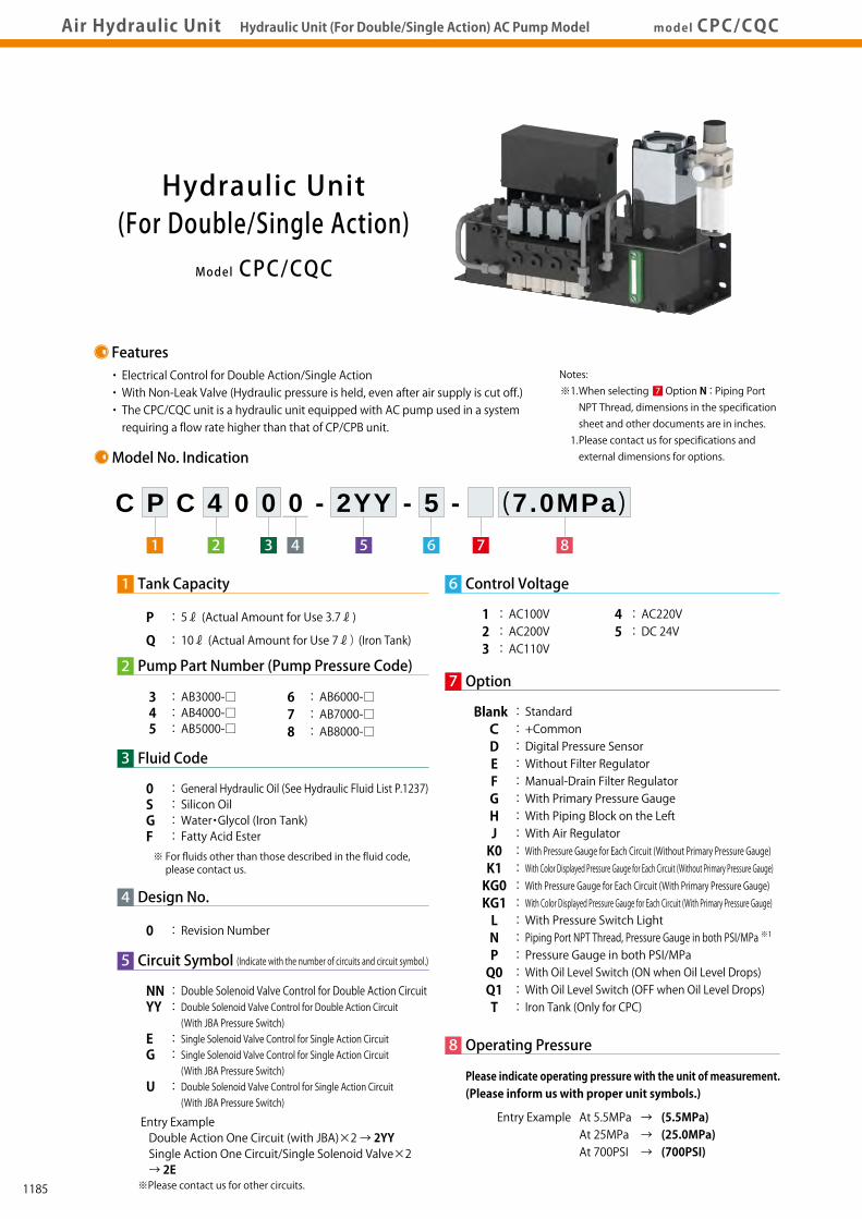
Air Hydraulic Unit Hydraulic Unit (For Double/Single Action) AC Pump ModelAir Hydraulic UnitDigest P.1169 Circuit Symbol External DimensionsModel No. Indication Specificationsmodel CPC/CQC
Model CPC/CQC
Model No. Indication
1 Tank Capacity
P : 5ℓ (Actual Amount for Use 3.7ℓ)
Q : 10ℓ (Actual Amount for Use 7ℓ) (Iron Tank)
4 Design No.
0 : Revision Number
2 Pump Part Number (Pump Pressure Code)
3 : AB3000-□ 4 : AB4000-□ 5 : AB5000-□
6 : AB6000-□ 7 : AB7000-□ 8 : AB8000-□
6 Control Voltage
1 : AC100V 2 : AC200V 3 : AC110V
4 : AC220V 5 : DC 24V
5 Circuit Symbol (Indicate with the number of circuits and circuit symbol.)
NN : Double Solenoid Valve Control for Double Action CircuitYY : Double Solenoid Valve Control for Double Action Circuit (With JBA Pressure Switch)E : Single Solenoid Valve Control for Single Action CircuitG : Single Solenoid Valve Control for Single Action Circuit (With JBA Pressure Switch)U : Double Solenoid Valve Control for Single Action Circuit (With JBA Pressure Switch)
7 Option
Blank : Standard C : +Common D : Digital Pressure Sensor E : Without Filter Regulator F : Manual-Drain Filter Regulator G : With Primary Pressure Gauge H : With Piping Block on the Left J : With Air Regulator K0 : With Pressure Gauge for Each Circuit (Without Primary Pressure Gauge) K1 : With Color Displayed Pressure Gauge for Each Circuit (Without Primary Pressure Gauge) KG0 : With Pressure Gauge for Each Circuit (With Primary Pressure Gauge) KG1 : With Color Displayed Pressure Gauge for Each Circuit (With Primary Pressure Gauge) L : With Pressure Switch Light N : Piping Port NPT Thread, Pressure Gauge in both PSI/MPa ※1
P : Pressure Gauge in both PSI/MPa Q0 : With Oil Level Switch (ON when Oil Level Drops) Q1 : With Oil Level Switch (OFF when Oil Level Drops) T : Iron Tank (Only for CPC)
8 Operating Pressure
Please indicate operating pressure with the unit of measurement. (Please inform us with proper unit symbols.)
3 Fluid Code
0 : General Hydraulic Oil (See Hydraulic Fluid List P.1237)S : Silicon OilG : Water・Glycol (Iron Tank)F : Fatty Acid Ester※ For fluids other than those described in the fluid code, please contact us.
41 2 3 6 7 85
C P C 4 0 0 0 - 2YY - 5 - (7.0MPa )
Hydraulic Unit(For Double/Single Action)
・ Electrical Control for Double Action/Single Action・ With Non-Leak Valve (Hydraulic pressure is held, even after air supply is cut off.)・ The CPC/CQC unit is a hydraulic unit equipped with AC pump used in a system requiring a flow rate higher than that of CP/CPB unit.
Features
※Please contact us for other circuits.
Entry Example Double Action One Circuit (with JBA)×2 → 2YY Single Action One Circuit/Single Solenoid Valve×2 → 2E
Entry Example At 5.5MPa → (5.5MPa) At 25MPa → (25.0MPa) At 700PSI → (700PSI)
Notes: ※1. When selecting Option N:Piping Port NPT Thread, dimensions in the specification sheet and other documents are in inches. 1. Please contact us for specifications and external dimensions for options.
7
A PortAC Pump
Solenoid Valve
BA Valve
Made by SMC (SYJ3140-□G)
A PortAC Pump
Solenoid Valve
BA ValvePressure Switch
Made by SMC (SYJ3140-□G)
A1 Port
A2 Port
AC Pump
Solenoid Valve
BA ValvePressure Switch
① ③
② ③
Made by SMC (SYJ3240-□G) B
A
⑥ ⑧
⑦ ⑧
BA
B Port
A Port
AC Pump
Solenoid Valve
Pressure Switch
① ③
② ③
Made by SMC (SYJ3240-□G) B
A
BA Valve
B Port
A Port
AC Pump
Solenoid Valve① ③
② ③
Made by SMC (SYJ3240-□G) B
A
BA Valve
Double Action 1 Circuit (With Pressure Switch)YYSingle Action 2 Circuit (With Pressure Switch)UU
Single Action 1 Circuit (With Pressure Switch)G
Double Action 1 CircuitNNSingle Action 1 CircuitE
PA Port
④ ⑤
④ ⑤
⑨ ⑩
④ ⑤
⑥ ⑦
PA Port
PA Port
PA Port
PA Port
① ②
AB
① ②
AB
Specifications
MPaNm3/min
ℓ
℃
Model No.Pump Part NumberNon-Leak Valve Part NumberDischarge Hydraulic Pressure ※1
Air ConsumptionTank CapacityControl VoltageOperating TemperatureUsable FluidOperation FrequencyPressure Switch Part Number (Pressure Increase Detection) ※2
Air Solenoid ValveSuction Filter
C□C30□0 C□C40□0 C□C50□0 C□C60□0 C□C70□0 C□C80□0 AC3001-□ AC4001-□ AC5001-□ AC6001-□ AC7001-□ AC8001-□ BA2011-0 BA2011-0 BA5011-0 BA5011-0 BA5011-0 BA5011-0 2.5~4.2 3.6~6.6 5.8~10.6 8.9~16.3 14.4~26.4 22.6~30.0 1.0 P:5ℓ( Actual Amount for Use 3.7ℓ ) / Q:10ℓ( Actual Amount for Use 7ℓ ) Model No. : Control Voltage 0 ~ 70 Model No. : Fluid Code Pump Operation Time : less than 500 hours/year (2 hrs/day) ※Actual Discharge Time
JBA0700-0G JBA0700-0G JBA0700-0G JBA2700-0G JBA2700-0G JBA2700-0G
Single Solenoid Valve: SYJ3140-□G / Double Solenoid Valve: SYJ3240-□G JF1030:174μm (100 mesh)
Notes : ※1. Discharge hydraulic pressure indicates when air pressure range is between 0.3 ~ 0.5MPa. For AC8001-□ pump, it indicates when air pressure range is between 0.3 to 0.38MPa due to the max. operating pressure of BA5011-0 valve. ※2. Standard setting value of pressure switch should be 70% of the operating pressure. 1. Please refer to the AB pump performance curve for the calculation formula and the volume of discharge hydraulic pressure (P.1195). 2. If hydraulic oil having viscosity higher than the shown, activating time increases. 3. In case of a low ambient temperature, action time increases because of high viscosity of hydraulic oil. 4. When the hydraulic circuit is equipped with a pressure gauge, install a damper or use an oil filled (glycerin) pressure gauge to prevent pressure gauge damage due to pressure surging. 5. Provide enough space at the bottom of the unit to compensate for hydraulic oil change. (Tank cleaning and suction strainer tightening becomes easier.)
Circuit Symbol/Circuit Reference
Circuit SymbolEG2GU2UNNYY2YY
Circuit (Reference)
Single ActionActuator Circuit
Double ActionActuator Circuit
Number of Circuits11212112
BA Valve Number of Connection11212224
Pressure Switch-○○○○-○○
Air Solenoid ValveSingle Solenoid ValveSingle Solenoid ValveSingle Solenoid ValveDouble Solenoid ValveDouble Solenoid ValveDouble Solenoid ValveDouble Solenoid ValveDouble Solenoid Valve
※Please contact us for other circuits.
1185

AirSequence Valve
BWD
HydraulicNon-Leak Coupler
BGA/BGB
BGC/BGD
BGP/BGS
BBP/BBS
BNP/BNS
BJP/BJS
BFP/BFS
Auto Coupler
JVC/JVD
JVA/JVB
JVE/JVF
JNA/JNB
JNC/JND
JLP/JLS
Hydraulic Valve
BK
BEQ
BT
BLS/BLG
BLB
JSS/JS
JKA/JKB
BMA/BMG
AU/AU-M
BU
AirHydraulic Unit
CV
Rotary Joint
JR
BP/JPB
BX
BEP/BSP
BH
BC
Pneumatic Series
Hydraulic Series
Valve / CouplerHydraulic Unit
Cautions / Others
High-PowerSeries
Manual OperationAccessories
AirHydraulic Unit
CV
CK
CP/CPB
CPC/CQC
CB
CC
AB/AB-V
AC/AC-V
Pneumatic Series
Hydraulic Series
Valve / CouplerHydraulic Unit
Cautions / Others
High-PowerSeries
Manual OperationAccessories
Air Hydraulic Unit Hydraulic Unit (For Double/Single Action) AC Pump ModelAir Hydraulic UnitDigest P.1169 Circuit Symbol External DimensionsModel No. Indication Specificationsmodel CPC/CQC
Model CPC/CQC
Model No. Indication
1 Tank Capacity
P : 5ℓ (Actual Amount for Use 3.7ℓ)
Q : 10ℓ (Actual Amount for Use 7ℓ) (Iron Tank)
4 Design No.
0 : Revision Number
2 Pump Part Number (Pump Pressure Code)
3 : AB3000-□ 4 : AB4000-□ 5 : AB5000-□
6 : AB6000-□ 7 : AB7000-□ 8 : AB8000-□
6 Control Voltage
1 : AC100V 2 : AC200V 3 : AC110V
4 : AC220V 5 : DC 24V
5 Circuit Symbol (Indicate with the number of circuits and circuit symbol.)
NN : Double Solenoid Valve Control for Double Action CircuitYY : Double Solenoid Valve Control for Double Action Circuit (With JBA Pressure Switch)E : Single Solenoid Valve Control for Single Action CircuitG : Single Solenoid Valve Control for Single Action Circuit (With JBA Pressure Switch)U : Double Solenoid Valve Control for Single Action Circuit (With JBA Pressure Switch)
7 Option
Blank : Standard C : +Common D : Digital Pressure Sensor E : Without Filter Regulator F : Manual-Drain Filter Regulator G : With Primary Pressure Gauge H : With Piping Block on the Left J : With Air Regulator K0 : With Pressure Gauge for Each Circuit (Without Primary Pressure Gauge) K1 : With Color Displayed Pressure Gauge for Each Circuit (Without Primary Pressure Gauge) KG0 : With Pressure Gauge for Each Circuit (With Primary Pressure Gauge) KG1 : With Color Displayed Pressure Gauge for Each Circuit (With Primary Pressure Gauge) L : With Pressure Switch Light N : Piping Port NPT Thread, Pressure Gauge in both PSI/MPa ※1
P : Pressure Gauge in both PSI/MPa Q0 : With Oil Level Switch (ON when Oil Level Drops) Q1 : With Oil Level Switch (OFF when Oil Level Drops) T : Iron Tank (Only for CPC)
8 Operating Pressure
Please indicate operating pressure with the unit of measurement. (Please inform us with proper unit symbols.)
3 Fluid Code
0 : General Hydraulic Oil (See Hydraulic Fluid List P.1237)S : Silicon OilG : Water・Glycol (Iron Tank)F : Fatty Acid Ester※ For fluids other than those described in the fluid code, please contact us.
41 2 3 6 7 85
C P C 4 0 0 0 - 2YY - 5 - (7.0MPa )
Hydraulic Unit(For Double/Single Action)
・ Electrical Control for Double Action/Single Action・ With Non-Leak Valve (Hydraulic pressure is held, even after air supply is cut off.)・ The CPC/CQC unit is a hydraulic unit equipped with AC pump used in a system requiring a flow rate higher than that of CP/CPB unit.
Features
※Please contact us for other circuits.
Entry Example Double Action One Circuit (with JBA)×2 → 2YY Single Action One Circuit/Single Solenoid Valve×2 → 2E
Entry Example At 5.5MPa → (5.5MPa) At 25MPa → (25.0MPa) At 700PSI → (700PSI)
Notes: ※1. When selecting Option N:Piping Port NPT Thread, dimensions in the specification sheet and other documents are in inches. 1. Please contact us for specifications and external dimensions for options.
7
A PortAC Pump
Solenoid Valve
BA Valve
Made by SMC (SYJ3140-□G)
A PortAC Pump
Solenoid Valve
BA ValvePressure Switch
Made by SMC (SYJ3140-□G)
A1 Port
A2 Port
AC Pump
Solenoid Valve
BA ValvePressure Switch
① ③
② ③
Made by SMC (SYJ3240-□G) B
A
⑥ ⑧
⑦ ⑧
BA
B Port
A Port
AC Pump
Solenoid Valve
Pressure Switch
① ③
② ③
Made by SMC (SYJ3240-□G) B
A
BA Valve
B Port
A Port
AC Pump
Solenoid Valve① ③
② ③
Made by SMC (SYJ3240-□G) B
A
BA Valve
Double Action 1 Circuit (With Pressure Switch)YYSingle Action 2 Circuit (With Pressure Switch)UU
Single Action 1 Circuit (With Pressure Switch)G
Double Action 1 CircuitNNSingle Action 1 CircuitE
PA Port
④ ⑤
④ ⑤
⑨ ⑩
④ ⑤
⑥ ⑦
PA Port
PA Port
PA Port
PA Port
① ②
AB
① ②
AB
Specifications
MPaNm3/min
ℓ
℃
Model No.Pump Part NumberNon-Leak Valve Part NumberDischarge Hydraulic Pressure ※1
Air ConsumptionTank CapacityControl VoltageOperating TemperatureUsable FluidOperation FrequencyPressure Switch Part Number (Pressure Increase Detection) ※2
Air Solenoid ValveSuction Filter
C□C30□0 C□C40□0 C□C50□0 C□C60□0 C□C70□0 C□C80□0 AC3001-□ AC4001-□ AC5001-□ AC6001-□ AC7001-□ AC8001-□ BA2011-0 BA2011-0 BA5011-0 BA5011-0 BA5011-0 BA5011-0 2.5~4.2 3.6~6.6 5.8~10.6 8.9~16.3 14.4~26.4 22.6~30.0 1.0 P:5ℓ( Actual Amount for Use 3.7ℓ ) / Q:10ℓ( Actual Amount for Use 7ℓ ) Model No. : Control Voltage 0 ~ 70 Model No. : Fluid Code Pump Operation Time : less than 500 hours/year (2 hrs/day) ※Actual Discharge Time
JBA0700-0G JBA0700-0G JBA0700-0G JBA2700-0G JBA2700-0G JBA2700-0G
Single Solenoid Valve: SYJ3140-□G / Double Solenoid Valve: SYJ3240-□G JF1030:174μm (100 mesh)
Notes : ※1. Discharge hydraulic pressure indicates when air pressure range is between 0.3 ~ 0.5MPa. For AC8001-□ pump, it indicates when air pressure range is between 0.3 to 0.38MPa due to the max. operating pressure of BA5011-0 valve. ※2. Standard setting value of pressure switch should be 70% of the operating pressure. 1. Please refer to the AB pump performance curve for the calculation formula and the volume of discharge hydraulic pressure (P.1195). 2. If hydraulic oil having viscosity higher than the shown, activating time increases. 3. In case of a low ambient temperature, action time increases because of high viscosity of hydraulic oil. 4. When the hydraulic circuit is equipped with a pressure gauge, install a damper or use an oil filled (glycerin) pressure gauge to prevent pressure gauge damage due to pressure surging. 5. Provide enough space at the bottom of the unit to compensate for hydraulic oil change. (Tank cleaning and suction strainer tightening becomes easier.)
Circuit Symbol/Circuit Reference
Circuit SymbolEG2GU2UNNYY2YY
Circuit (Reference)
Single ActionActuator Circuit
Double ActionActuator Circuit
Number of Circuits11212112
BA Valve Number of Connection11212224
Pressure Switch-○○○○-○○
Air Solenoid ValveSingle Solenoid ValveSingle Solenoid ValveSingle Solenoid ValveDouble Solenoid ValveDouble Solenoid ValveDouble Solenoid ValveDouble Solenoid ValveDouble Solenoid Valve
※Please contact us for other circuits.
1186

AirSequence Valve
BWD
HydraulicNon-Leak Coupler
BGA/BGB
BGC/BGD
BGP/BGS
BBP/BBS
BNP/BNS
BJP/BJS
BFP/BFS
Auto Coupler
JVC/JVD
JVA/JVB
JVE/JVF
JNA/JNB
JNC/JND
JLP/JLS
Hydraulic Valve
BK
BEQ
BT
BLS/BLG
BLB
JSS/JS
JKA/JKB
BMA/BMG
AU/AU-M
BU
AirHydraulic Unit
CV
Rotary Joint
JR
BP/JPB
BX
BEP/BSP
BH
BC
Pneumatic Series
Hydraulic Series
Valve / CouplerHydraulic Unit
Cautions / Others
High-PowerSeries
Manual OperationAccessories
AirHydraulic Unit
CV
CK
CP/CPB
CPC/CQC
CB
CC
AB/AB-V
AC/AC-V
Pneumatic Series
Hydraulic Series
Valve / CouplerHydraulic Unit
Cautions / Others
High-PowerSeries
Manual OperationAccessories
Air Hydraulic Unit Hydraulic Unit (For Double/Single Action) AC Pump Model model CPC/CQCAir Hydraulic UnitDigest P.1169 Circuit Symbol External DimensionsModel No. Indication Specifications
External Dimensions:CQCExternal Dimensions:CPC
BA Valve Number of ConnectionA
1 Connection 2 Connections 3 Connections 4 Connections 259 209 159 109
A1 A2 A□
1 15
H5.0
L1.3
AB
OIL
7
36
205
241.5
71
238
545
65480
460 10
110
10
25
50A10
145
15.5
285
385
115
70
BA Valve Number of ConnectionA
1 Connection 2 Connections 3 Connections 4 Connections 345.5 295.5 245.5 195.5
A1 A2 A□
1 15
OIL
AB
650
50600
560 20
70
20
89
50A25
145
10
285
385
90
90
10
60
57
190
291.5
7
95
40110
283
2056020
Conduit Hole1-φ28
Air Solenoid Valve
Oil Supply Port
4-M10x1.5 Bolt HoleM10x1.5x20 Bolt (Included)JIS Spring Washer
JBA Pressure Switch
AC Pump
Filter Regulator(Auto Drain)
PA PortRc1/2 Thread
Air Pressure Gauge
Terminal Block
Air Bleed Valve
BA Valve
A PortRc1/4 Thread
Drain Port
(M12x1.5 Thread)
Drain Port
(Applicable Tube Diameter φ10)
8-M10x1.5 Bolt Hole4-M10x1.5x20 Bolt (Included)JIS Spring Washer
JBA Pressure Switch
AC PumpFilter Regulator(Auto Drain)
PA PortRc1/2 Thread
Air Pressure Gauge
Terminal Block Air Bleed Valve
BA Valve
A PortRc1/4 Thread
Drain Port(Rc1/4 Thread)
Drain Port(Applicable Tube Diameter φ10)
Conduit Hole1-φ28
Air Solenoid Valve
Oil Supply Port
Notes : 1. Please contact us for specifications and external dimensions for options. 2. The external dimensions for five or more circuits are different. Please contact us for further information.
Notes : 1. Please contact us for specifications and external dimensions for options. 2. The external dimensions for five or more circuits are different. Please contact us for further information.
DistanceDistance
1187
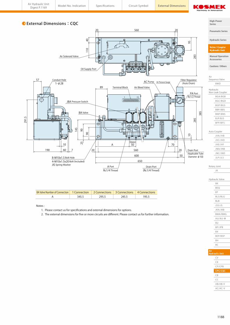
AirSequence Valve
BWD
HydraulicNon-Leak Coupler
BGA/BGB
BGC/BGD
BGP/BGS
BBP/BBS
BNP/BNS
BJP/BJS
BFP/BFS
Auto Coupler
JVC/JVD
JVA/JVB
JVE/JVF
JNA/JNB
JNC/JND
JLP/JLS
Hydraulic Valve
BK
BEQ
BT
BLS/BLG
BLB
JSS/JS
JKA/JKB
BMA/BMG
AU/AU-M
BU
AirHydraulic Unit
CV
Rotary Joint
JR
BP/JPB
BX
BEP/BSP
BH
BC
Pneumatic Series
Hydraulic Series
Valve / CouplerHydraulic Unit
Cautions / Others
High-PowerSeries
Manual OperationAccessories
AirHydraulic Unit
CV
CK
CP/CPB
CPC/CQC
CB
CC
AB/AB-V
AC/AC-V
Pneumatic Series
Hydraulic Series
Valve / CouplerHydraulic Unit
Cautions / Others
High-PowerSeries
Manual OperationAccessories
Air Hydraulic Unit Hydraulic Unit (For Double/Single Action) AC Pump Model model CPC/CQCAir Hydraulic UnitDigest P.1169 Circuit Symbol External DimensionsModel No. Indication Specifications
External Dimensions:CQCExternal Dimensions:CPC
BA Valve Number of ConnectionA
1 Connection 2 Connections 3 Connections 4 Connections 259 209 159 109
A1 A2 A□
1 15
H5.0
L1.3
AB
OIL
7
36
205
241.5
71
238
545
65480
460 10
110
10
25
50A10
145
15.5
285
385
115
70
BA Valve Number of ConnectionA
1 Connection 2 Connections 3 Connections 4 Connections 345.5 295.5 245.5 195.5
A1 A2 A□
1 15
OIL
AB
650
50600
560 20
70
20
89
50A25
145
10
285
385
90
90
10
60
57
190
291.5
7
95
40110
283
2056020
Conduit Hole1-φ28
Air Solenoid Valve
Oil Supply Port
4-M10x1.5 Bolt HoleM10x1.5x20 Bolt (Included)JIS Spring Washer
JBA Pressure Switch
AC Pump
Filter Regulator(Auto Drain)
PA PortRc1/2 Thread
Air Pressure Gauge
Terminal Block
Air Bleed Valve
BA Valve
A PortRc1/4 Thread
Drain Port
(M12x1.5 Thread)
Drain Port
(Applicable Tube Diameter φ10)
8-M10x1.5 Bolt Hole4-M10x1.5x20 Bolt (Included)JIS Spring Washer
JBA Pressure Switch
AC PumpFilter Regulator(Auto Drain)
PA PortRc1/2 Thread
Air Pressure Gauge
Terminal Block Air Bleed Valve
BA Valve
A PortRc1/4 Thread
Drain Port(Rc1/4 Thread)
Drain Port(Applicable Tube Diameter φ10)
Conduit Hole1-φ28
Air Solenoid Valve
Oil Supply Port
Notes : 1. Please contact us for specifications and external dimensions for options. 2. The external dimensions for five or more circuits are different. Please contact us for further information.
Notes : 1. Please contact us for specifications and external dimensions for options. 2. The external dimensions for five or more circuits are different. Please contact us for further information.
DistanceDistance
1188

AirSequence Valve
BWD
HydraulicNon-Leak Coupler
BGA/BGB
BGC/BGD
BGP/BGS
BBP/BBS
BNP/BNS
BJP/BJS
BFP/BFS
Auto Coupler
JVC/JVD
JVA/JVB
JVE/JVF
JNA/JNB
JNC/JND
JLP/JLS
Hydraulic Valve
BK
BEQ
BT
BLS/BLG
BLB
JSS/JS
JKA/JKB
AU/AU-M
BU
AirHydraulic Unit
CV
Rotary Joint
JR
BP/JPB
BX
BEP/BSP
BH
BC
Pneumatic Series
Hydraulic Series
Valve / CouplerHydraulic Unit
Cautions / Others
High-PowerSeries
Manual OperationAccessories
AirSequence Valve
BWD
HydraulicNon-Leak Coupler
BGA/BGB
BGC/BGD
BGP/BGS
BBP/BBS
BNP/BNS
BJP/BJS
BFP/BFS
Auto Coupler
JVC/JVD
JVA/JVB
JVE/JVF
JNA/JNB
JNC/JND
JLP/JLS
Hydraulic Valve
BK
BEQ
BT
BLS/BLG
BLB
JSS/JS
JKA/JKB
BMA/BMG
AU/AU-M
BU
AirHydraulic Unit
CV
CK
CP/CPB
CPC/CQC
CB
CC
AB/AB-V
AC/AC-V
Rotary Joint
JR
BP/JPB
BX
BEP/BSP
BH
BC
Pneumatic Series
Hydraulic Series
Valve / CouplerHydraulic Unit
Cautions / Others
High-PowerSeries
Manual OperationAccessories
Air Hydraulic Unit Pump Unit BC/BH Combination Model (AB Pump) model CBAir Hydraulic UnitDigest P.1169 Circuit Symbol External DimensionsModel No. Indication Specifications
Model CB
・Pump Unit to use in conjunction with BC / BH Unit
・Compact with AB Pump Installed※Please refer to P.1165, P.1167 for BC/BH non-leak valve unit.
Features
Specifications
Circuit Symbol
External Dimensions
Application Example
MPaNm3/min
ℓ℃
Model No.Pump Part NumberDischarge Hydraulic Pressure ※1 ※2
Air ConsumptionTank CapacityOperating TemperatureUsable FluidOperation Frequency
CB□030 CB□040 CB□050 CB□060 CB□070 CB□080 AB3000-□ AB4000-□ AB5000-□ AB6000-□ AB7000-□ AB8000-□ 2.4~4.3 3.9~7.0 6.0~11.0 10.0~17.5 15.5~27.0 25.0~43.5 0.4 2:2ℓ (Actual Amount for Use 1.1ℓ) / 5:5ℓ (Actual Amount for Use 3.1ℓ) 0 ~ 70 Model No. : Fluid Code Pump Operation Time : less than 500 hours/year (2 hrs/day) ※Actual Discharge Time
Model No. Indication
1
21 54 63
Tank Capacity
2 : 2ℓ (Actual Amount for Use 1.1ℓ)
5 : 5ℓ (Actual Amount for Use 3.1ℓ)
CB 2 04 0 - 0 -
3 Design No.
0 : Revision Number
2 Pump Part Number (Pump Pressure Code)
03 : AB3000-□
04 : AB4000-□
05 : AB5000-□
06 : AB6000-□
07 : AB7000-□
08 : AB8000-□
5 Option
Blank : Standard (Air Regulator)
D : With Filter Regulator (Automatic Drain Option)
Q : With Level Switch
4 Fluid Code
0 : General Hydraulic Oil (See Hydraulic Fluid List P. 1237)
S : Silicon Oil
G : Water-Glycol (except AB8000) (Tank is made of steel.)
6 Unit of Pressure Gauge
Blank : MPa (Standard)
P : PSI
Notes : ※1. Discharge hydraulic pressure indicates when air pressure range is between 0.3 ~ 0.5MPa. ※2. Please be careful of the operating pressure range of BH / BC unit to be used in combination. Example : In case of using CB□080 and BH0071 together, actual operating pressure range is 25 to 30MPa. (CB□080 range = 25 to 43.5MPa, BH0071 range = 6 to 30MPa) . 1. Please refer to the AB pump performance curve for the calculation formula and the volume of discharge hydraulic pressure (P.1195).
※ For fluids other than those described in the fluid code, please contact us.
A manual operation of double action cylinder in combination with BH (NN circuit).
CB Pump UnitBH Non-Leak Valve Unit
Pump Unit(For Double/Single Action)
PH Port
R Port PA Port
OIL
H 1.4
L 0.3
230
44.5 48 65
AB Pump
Air Bleed Valve
Air PressureGauge Air Regulator
Oil Supply Port
55
75
151
10
4.5161
166
155175
2ℓ Tank
10
8050
287
239.5
130
42
147
R PortRc1/4 Thread
PA PortRc1/4 Thread
4-M8 Bolt hole4-M8×1.25×16 BoltWith Spring Washer (Included)
PH PortRc1/4 Thread
Note : 1. Please contact us for the specification (5.0ℓ tank, water-glycol, with filter regulator, level switch etc.) other than the drawing above.
※This drawing is for 2 liter tank.
1189

AirSequence Valve
BWD
HydraulicNon-Leak Coupler
BGA/BGB
BGC/BGD
BGP/BGS
BBP/BBS
BNP/BNS
BJP/BJS
BFP/BFS
Auto Coupler
JVC/JVD
JVA/JVB
JVE/JVF
JNA/JNB
JNC/JND
JLP/JLS
Hydraulic Valve
BK
BEQ
BT
BLS/BLG
BLB
JSS/JS
JKA/JKB
AU/AU-M
BU
AirHydraulic Unit
CV
Rotary Joint
JR
BP/JPB
BX
BEP/BSP
BH
BC
Pneumatic Series
Hydraulic Series
Valve / CouplerHydraulic Unit
Cautions / Others
High-PowerSeries
Manual OperationAccessories
AirSequence Valve
BWD
HydraulicNon-Leak Coupler
BGA/BGB
BGC/BGD
BGP/BGS
BBP/BBS
BNP/BNS
BJP/BJS
BFP/BFS
Auto Coupler
JVC/JVD
JVA/JVB
JVE/JVF
JNA/JNB
JNC/JND
JLP/JLS
Hydraulic Valve
BK
BEQ
BT
BLS/BLG
BLB
JSS/JS
JKA/JKB
BMA/BMG
AU/AU-M
BU
AirHydraulic Unit
CV
CK
CP/CPB
CPC/CQC
CB
CC
AB/AB-V
AC/AC-V
Rotary Joint
JR
BP/JPB
BX
BEP/BSP
BH
BC
Pneumatic Series
Hydraulic Series
Valve / CouplerHydraulic Unit
Cautions / Others
High-PowerSeries
Manual OperationAccessories
Air Hydraulic Unit Pump Unit BC/BH Combination Model (AB Pump) model CBAir Hydraulic UnitDigest P.1169 Circuit Symbol External DimensionsModel No. Indication Specifications
Model CB
・Pump Unit to use in conjunction with BC / BH Unit
・Compact with AB Pump Installed※Please refer to P.1165, P.1167 for BC/BH non-leak valve unit.
Features
Specifications
Circuit Symbol
External Dimensions
Application Example
MPaNm3/min
ℓ℃
Model No.Pump Part NumberDischarge Hydraulic Pressure ※1 ※2
Air ConsumptionTank CapacityOperating TemperatureUsable FluidOperation Frequency
CB□030 CB□040 CB□050 CB□060 CB□070 CB□080 AB3000-□ AB4000-□ AB5000-□ AB6000-□ AB7000-□ AB8000-□ 2.4~4.3 3.9~7.0 6.0~11.0 10.0~17.5 15.5~27.0 25.0~43.5 0.4 2:2ℓ (Actual Amount for Use 1.1ℓ) / 5:5ℓ (Actual Amount for Use 3.1ℓ) 0 ~ 70 Model No. : Fluid Code Pump Operation Time : less than 500 hours/year (2 hrs/day) ※Actual Discharge Time
Model No. Indication
1
21 54 63
Tank Capacity
2 : 2ℓ (Actual Amount for Use 1.1ℓ)
5 : 5ℓ (Actual Amount for Use 3.1ℓ)
CB 2 04 0 - 0 -
3 Design No.
0 : Revision Number
2 Pump Part Number (Pump Pressure Code)
03 : AB3000-□
04 : AB4000-□
05 : AB5000-□
06 : AB6000-□
07 : AB7000-□
08 : AB8000-□
5 Option
Blank : Standard (Air Regulator)
D : With Filter Regulator (Automatic Drain Option)
Q : With Level Switch
4 Fluid Code
0 : General Hydraulic Oil (See Hydraulic Fluid List P. 1237)
S : Silicon Oil
G : Water-Glycol (except AB8000) (Tank is made of steel.)
6 Unit of Pressure Gauge
Blank : MPa (Standard)
P : PSI
Notes : ※1. Discharge hydraulic pressure indicates when air pressure range is between 0.3 ~ 0.5MPa. ※2. Please be careful of the operating pressure range of BH / BC unit to be used in combination. Example : In case of using CB□080 and BH0071 together, actual operating pressure range is 25 to 30MPa. (CB□080 range = 25 to 43.5MPa, BH0071 range = 6 to 30MPa) . 1. Please refer to the AB pump performance curve for the calculation formula and the volume of discharge hydraulic pressure (P.1195).
※ For fluids other than those described in the fluid code, please contact us.
A manual operation of double action cylinder in combination with BH (NN circuit).
CB Pump UnitBH Non-Leak Valve Unit
Pump Unit(For Double/Single Action)
PH Port
R Port PA Port
OIL
H 1.4
L 0.3
230
44.5 48 65
AB Pump
Air Bleed Valve
Air PressureGauge Air Regulator
Oil Supply Port
5575
151
10
4.5
161
166
155175
2ℓ Tank
10
8050
287
239.5
130
42
147
R PortRc1/4 Thread
PA PortRc1/4 Thread
4-M8 Bolt hole4-M8×1.25×16 BoltWith Spring Washer (Included)
PH PortRc1/4 Thread
Note : 1. Please contact us for the specification (5.0ℓ tank, water-glycol, with filter regulator, level switch etc.) other than the drawing above.
※This drawing is for 2 liter tank.
1190
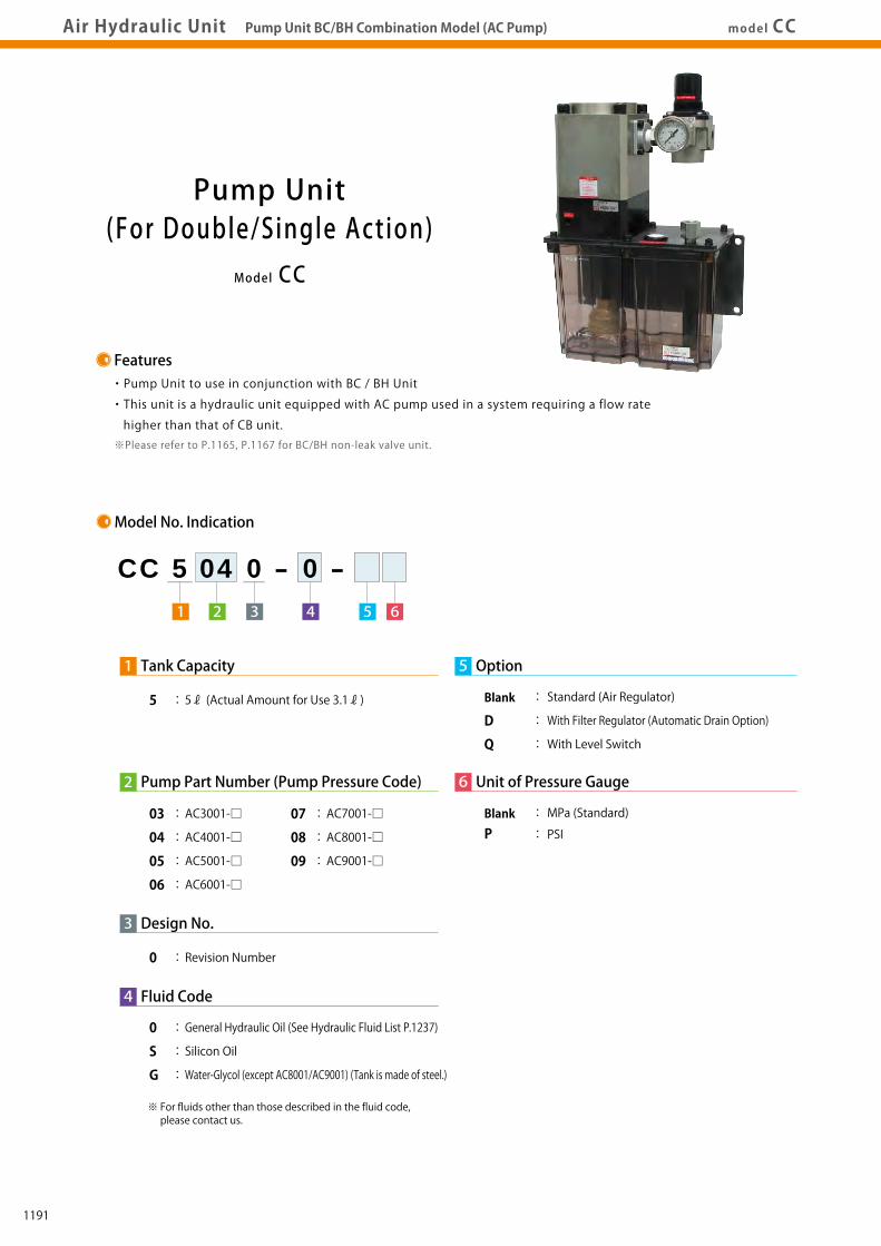
AirSequence Valve
BWD
HydraulicNon-Leak Coupler
BGA/BGB
BGC/BGD
BGP/BGS
BBP/BBS
BNP/BNS
BJP/BJS
BFP/BFS
Auto Coupler
JVC/JVD
JVA/JVB
JVE/JVF
JNA/JNB
JNC/JND
JLP/JLS
Hydraulic Valve
BK
BEQ
BT
BLS/BLG
BLB
JSS/JS
JKA/JKB
AU/AU-M
BU
AirHydraulic Unit
CV
Rotary Joint
JR
BP/JPB
BX
BEP/BSP
BH
BC
Pneumatic Series
Hydraulic Series
Valve / CouplerHydraulic Unit
Cautions / Others
High-PowerSeries
Manual OperationAccessories
AirSequence Valve
BWD
HydraulicNon-Leak Coupler
BGA/BGB
BGC/BGD
BGP/BGS
BBP/BBS
BNP/BNS
BJP/BJS
BFP/BFS
Auto Coupler
JVC/JVD
JVA/JVB
JVE/JVF
JNA/JNB
JNC/JND
JLP/JLS
Hydraulic Valve
BK
BEQ
BT
BLS/BLG
BLB
JSS/JS
JKA/JKB
BMA/BMG
AU/AU-M
BU
AirHydraulic Unit
CV
CK
CP/CPB
CPC/CQC
CB
CC
AB/AB-V
AC/AC-V
Rotary Joint
JR
BP/JPB
BX
BEP/BSP
BH
BC
Pneumatic Series
Hydraulic Series
Valve / CouplerHydraulic Unit
Cautions / Others
High-PowerSeries
Manual OperationAccessories
Air Hydraulic Unit Pump Unit BC/BH Combination Model (AC Pump) model CCAir Hydraulic UnitDigest P.1169 Circuit Symbol External DimensionsModel No. Indication Specifications
Model CC
・Pump Unit to use in conjunction with BC / BH Unit
・This unit is a hydraulic unit equipped with AC pump used in a system requiring a flow rate
higher than that of CB unit.※Please refer to P.1165, P.1167 for BC/BH non-leak valve unit.
Features
Specifications
Circuit Symbol
External Dimensions
Application Example
MPaNm3/min
ℓ℃
Model No.Pump Part NumberDischarge Hydraulic Pressure ※1 ※2
Air ConsumptionTank CapacityOperating TemperatureUsable FluidOperation Frequency
CC5030 CC5040 CC5050 CC5060 CC5070 CC5080 CC5090 AC3001-□ AC4001-□ AC5001-□ AC6001-□ AC7001-□ AC8001-□ AC9001-□ 2.3~4.2 3.6~6.6 5.8~10.6 8.9~16.3 14.4~26.4 22.6~41.4 35.3~64.7 1.0 5ℓ (Actual Amount for Use 3.1ℓ) 0 ~ 70 Model No. : Fluid Code Pump Operation Time : less than 500 hours/year (2 hrs/day) ※Actual Discharge Time
Model No. Indication
1
21 54 63
Tank Capacity
5 : 5ℓ (Actual Amount for Use 3.1ℓ)
CC 5 04 0 - 0 -
3 Design No.
0 : Revision Number
2 Pump Part Number (Pump Pressure Code)
03 : AC3001-□
04 : AC4001-□
05 : AC5001-□
06 : AC6001-□
07 : AC7001-□
08 : AC8001-□
09 : AC9001-□
5 Option
Blank : Standard (Air Regulator)
D : With Filter Regulator (Automatic Drain Option)
Q : With Level Switch
4 Fluid Code
0 : General Hydraulic Oil (See Hydraulic Fluid List P.1237)
S : Silicon Oil
G : Water-Glycol (except AC8001/AC9001) (Tank is made of steel.)
6 Unit of Pressure Gauge
Blank : MPa (Standard)
P : PSI
Notes : ※1. Discharge hydraulic pressure indicates when air pressure range is between 0.3 ~ 0.5MPa. ※2. Please be careful of the operating pressure range of BH / BC unit to be used in combination. Example : In case of using CC5080 and BH0071 together, actual operating pressure range is 22.6 to 30MPa. (CC5080 range = 22.6 to 41.4MPa, BH0071 range = 6 to 30MPa) . 1. Please refer to the AB pump performance curve for the calculation formula and the volume of discharge hydraulic pressure (P.1195).
A manual operation of double action cylinder in combination with BH (NN circuit).
CC Pump UnitBH Non-Leak Valve Unit
Pump CodeS
AC3001/AC4001 AC5001~AC9001 Rc3/8 Rc1/4
※ For fluids other than those described in the fluid code, please contact us.
Pump Unit(For Double/Single Action)
PH Port
R Port PA Port
H 3.8
L 0.7
OIL
84 163 33
AC Pump
Air Bleed Valve
Air Pressure Gauge
134
203
10
6
260280
5ℓ Tank
10
110
50
421
321
159
88
167
PA PortRc1/2 Thread
4-M8 Bolt Hole4-M8×1.25×20 BoltWith Spring Washer (Included)
PH PortS Screw
Note :
1. Please contact us for the specification (water-glycol, with filter regulator, level switch etc.) other than the drawing above.
181 213
Air Regulator
R PortRc3/8 Thread
Oil Supply Port5612
1191

AirSequence Valve
BWD
HydraulicNon-Leak Coupler
BGA/BGB
BGC/BGD
BGP/BGS
BBP/BBS
BNP/BNS
BJP/BJS
BFP/BFS
Auto Coupler
JVC/JVD
JVA/JVB
JVE/JVF
JNA/JNB
JNC/JND
JLP/JLS
Hydraulic Valve
BK
BEQ
BT
BLS/BLG
BLB
JSS/JS
JKA/JKB
AU/AU-M
BU
AirHydraulic Unit
CV
Rotary Joint
JR
BP/JPB
BX
BEP/BSP
BH
BC
Pneumatic Series
Hydraulic Series
Valve / CouplerHydraulic Unit
Cautions / Others
High-PowerSeries
Manual OperationAccessories
AirSequence Valve
BWD
HydraulicNon-Leak Coupler
BGA/BGB
BGC/BGD
BGP/BGS
BBP/BBS
BNP/BNS
BJP/BJS
BFP/BFS
Auto Coupler
JVC/JVD
JVA/JVB
JVE/JVF
JNA/JNB
JNC/JND
JLP/JLS
Hydraulic Valve
BK
BEQ
BT
BLS/BLG
BLB
JSS/JS
JKA/JKB
BMA/BMG
AU/AU-M
BU
AirHydraulic Unit
CV
CK
CP/CPB
CPC/CQC
CB
CC
AB/AB-V
AC/AC-V
Rotary Joint
JR
BP/JPB
BX
BEP/BSP
BH
BC
Pneumatic Series
Hydraulic Series
Valve / CouplerHydraulic Unit
Cautions / Others
High-PowerSeries
Manual OperationAccessories
Air Hydraulic Unit Pump Unit BC/BH Combination Model (AC Pump) model CCAir Hydraulic UnitDigest P.1169 Circuit Symbol External DimensionsModel No. Indication Specifications
Model CC
・Pump Unit to use in conjunction with BC / BH Unit
・This unit is a hydraulic unit equipped with AC pump used in a system requiring a flow rate
higher than that of CB unit.※Please refer to P.1165, P.1167 for BC/BH non-leak valve unit.
Features
Specifications
Circuit Symbol
External Dimensions
Application Example
MPaNm3/min
ℓ℃
Model No.Pump Part NumberDischarge Hydraulic Pressure ※1 ※2
Air ConsumptionTank CapacityOperating TemperatureUsable FluidOperation Frequency
CC5030 CC5040 CC5050 CC5060 CC5070 CC5080 CC5090 AC3001-□ AC4001-□ AC5001-□ AC6001-□ AC7001-□ AC8001-□ AC9001-□ 2.3~4.2 3.6~6.6 5.8~10.6 8.9~16.3 14.4~26.4 22.6~41.4 35.3~64.7 1.0 5ℓ (Actual Amount for Use 3.1ℓ) 0 ~ 70 Model No. : Fluid Code Pump Operation Time : less than 500 hours/year (2 hrs/day) ※Actual Discharge Time
Model No. Indication
1
21 54 63
Tank Capacity
5 : 5ℓ (Actual Amount for Use 3.1ℓ)
CC 5 04 0 - 0 -
3 Design No.
0 : Revision Number
2 Pump Part Number (Pump Pressure Code)
03 : AC3001-□
04 : AC4001-□
05 : AC5001-□
06 : AC6001-□
07 : AC7001-□
08 : AC8001-□
09 : AC9001-□
5 Option
Blank : Standard (Air Regulator)
D : With Filter Regulator (Automatic Drain Option)
Q : With Level Switch
4 Fluid Code
0 : General Hydraulic Oil (See Hydraulic Fluid List P.1237)
S : Silicon Oil
G : Water-Glycol (except AC8001/AC9001) (Tank is made of steel.)
6 Unit of Pressure Gauge
Blank : MPa (Standard)
P : PSI
Notes : ※1. Discharge hydraulic pressure indicates when air pressure range is between 0.3 ~ 0.5MPa. ※2. Please be careful of the operating pressure range of BH / BC unit to be used in combination. Example : In case of using CC5080 and BH0071 together, actual operating pressure range is 22.6 to 30MPa. (CC5080 range = 22.6 to 41.4MPa, BH0071 range = 6 to 30MPa) . 1. Please refer to the AB pump performance curve for the calculation formula and the volume of discharge hydraulic pressure (P.1195).
A manual operation of double action cylinder in combination with BH (NN circuit).
CC Pump UnitBH Non-Leak Valve Unit
Pump CodeS
AC3001/AC4001 AC5001~AC9001 Rc3/8 Rc1/4
※ For fluids other than those described in the fluid code, please contact us.
Pump Unit(For Double/Single Action)
PH Port
R Port PA Port
H 3.8
L 0.7
OIL
84 163 33
AC Pump
Air Bleed Valve
Air Pressure Gauge
134
203
10
6
260280
5ℓ Tank
10
110
50
421
321
159
88
167
PA PortRc1/2 Thread
4-M8 Bolt Hole4-M8×1.25×20 BoltWith Spring Washer (Included)
PH PortS Screw
Note :
1. Please contact us for the specification (water-glycol, with filter regulator, level switch etc.) other than the drawing above.
181 213
Air Regulator
R PortRc3/8 Thread
Oil Supply Port5612
1192
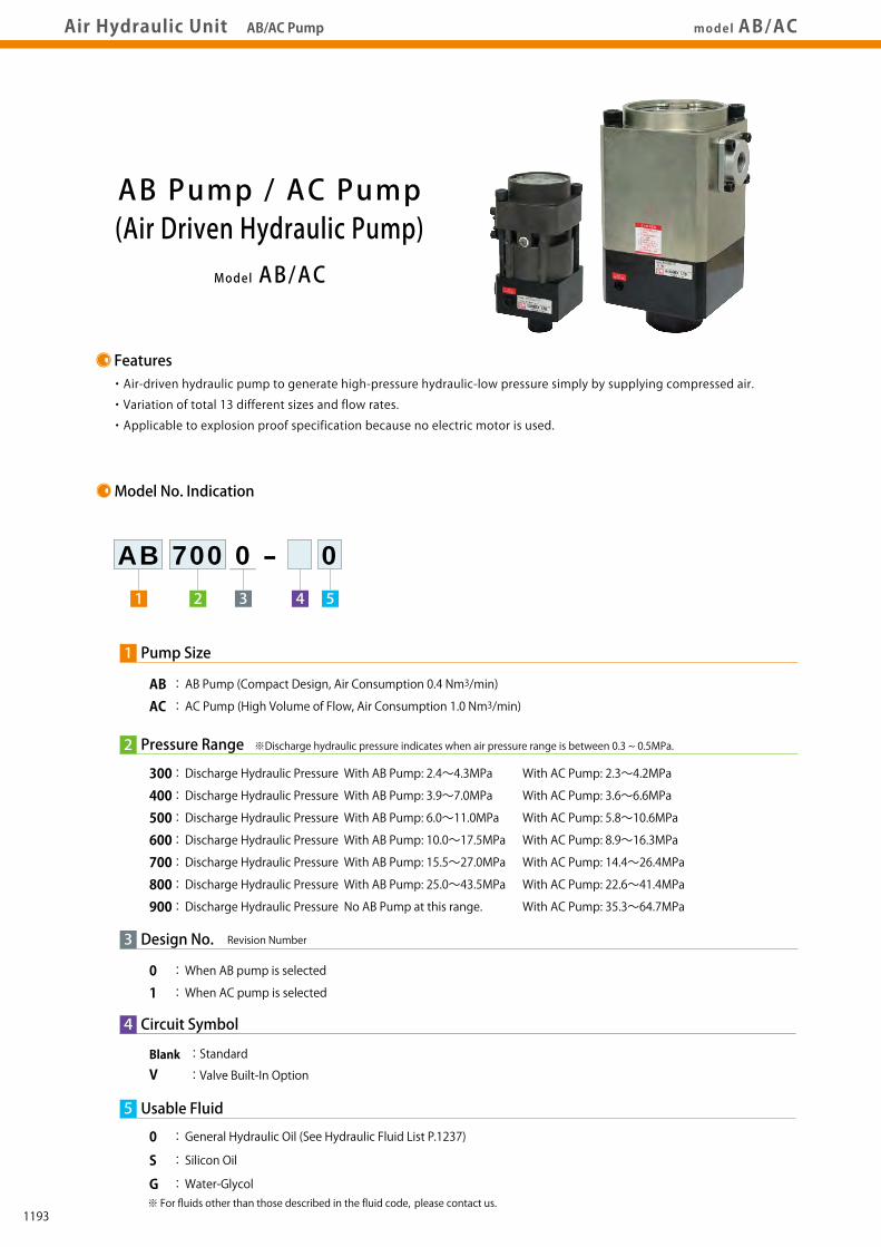
AirSequence Valve
BWD
HydraulicNon-Leak Coupler
BGA/BGB
BGC/BGD
BGP/BGS
BBP/BBS
BNP/BNS
BJP/BJS
BFP/BFS
Auto Coupler
JVC/JVD
JVA/JVB
JVE/JVF
JNA/JNB
JNC/JND
JLP/JLS
Hydraulic Valve
BK
BEQ
BT
BLS/BLG
BLB
JSS/JS
JKA/JKB
AU/AU-M
BU
AirHydraulic Unit
CV
Rotary Joint
JR
BP/JPB
BX
BEP/BSP
BH
BC
Pneumatic Series
Hydraulic Series
Valve / CouplerHydraulic Unit
Cautions / Others
High-PowerSeries
Manual OperationAccessories
AirSequence Valve
BWD
HydraulicNon-Leak Coupler
BGA/BGB
BGC/BGD
BGP/BGS
BBP/BBS
BNP/BNS
BJP/BJS
BFP/BFS
Auto Coupler
JVC/JVD
JVA/JVB
JVE/JVF
JNA/JNB
JNC/JND
JLP/JLS
Hydraulic Valve
BK
BEQ
BT
BLS/BLG
BLB
JSS/JS
JKA/JKB
BMA/BMG
AU/AU-M
BU
AirHydraulic Unit
CV
CK
CP/CPB
CPC/CQC
CB
CC
AB/AB-V
AC/AC-V
Rotary Joint
JR
BP/JPB
BX
BEP/BSP
BH
BC
Pneumatic Series
Hydraulic Series
Valve / CouplerHydraulic Unit
Cautions / Others
High-PowerSeries
Manual OperationAccessories
Air Hydraulic UnitDigest P.1169
PerformanceCurve
ActionDescription AccessoriesExternal
Dimensions CautionsModel No.Indication Specifications Circuit
SymbolAir Hydraulic Unit AB/AC Pump model AB/AC
Model AB/AC
AB Pump / AC Pump(Air Driven Hydraulic Pump)
・Air-driven hydraulic pump to generate high-pressure hydraulic-low pressure simply by supplying compressed air.
・Variation of total 13 different sizes and flow rates.
・Applicable to explosion proof specification because no electric motor is used.
Features
Model No. Indication
1
2 4 51 3
Pump Size
AB : AB Pump (Compact Design, Air Consumption 0.4 Nm3/min)AC : AC Pump (High Volume of Flow, Air Consumption 1.0 Nm3/min)
AB 700 0 - 0
3 Design No.
0 : When AB pump is selected1 : When AC pump is selected
Revision Number
2 Pressure Range
300 : Discharge Hydraulic Pressure With AB Pump: 2.4~4.3MPa With AC Pump: 2.3~4.2MPa
400 : Discharge Hydraulic Pressure With AB Pump: 3.9~7.0MPa With AC Pump: 3.6~6.6MPa
500 : Discharge Hydraulic Pressure With AB Pump: 6.0~11.0MPa With AC Pump: 5.8~10.6MPa
600 : Discharge Hydraulic Pressure With AB Pump: 10.0~17.5MPa With AC Pump: 8.9~16.3MPa700 : Discharge Hydraulic Pressure With AB Pump: 15.5~27.0MPa With AC Pump: 14.4~26.4MPa800 : Discharge Hydraulic Pressure With AB Pump: 25.0~43.5MPa With AC Pump: 22.6~41.4MPa900 : Discharge Hydraulic Pressure No AB Pump at this range. With AC Pump: 35.3~64.7MPa
5 Usable Fluid
0 : General Hydraulic Oil (See Hydraulic Fluid List P.1237)
S : Silicon Oil
G : Water-Glycol
4 Circuit Symbol
Blank : Standard
V : Valve Built-In Option
Specifications
Circuit Symbol
Action Description
MPaNm3/min
MPamdB
kg
Model No.Discharge Hydraulic Pressure ※1
Air ConsumptionOperating Air Pressure RangeLiftNoiseUsable Fluid ※2
Applicable Suction Filter ※3
Mass
AC3001-□□ AC4001-□□ AC5001-□□ AC6001-□□ AC7001-□□ AC8001-□□ AC9001-□□ 2.3~4.2 3.6~6.6 5.8~10.6 8.9~16.3 14.4~26.4 22.6~41.4 35.3~64.7 1.0 0.15 ~ 0.7 below 1.0 82~85 Model No. : Fluid Code JF1040 JF1030 8.8
MPaNm3/min
MPamdB
kg
Model No.Discharge Hydraulic Pressure ※1
Air ConsumptionOperating Air Pressure RangeLiftNoiseUsable Fluid ※2
Applicable Suction Filter ※3
Mass
AB3000-□□ AB4000-□□ AB5000-□□ AB6000-□□ AB7000-□□ AB8000-□□ 2.4~4.3 3.9~7.0 6.0~11.0 10.0~17.5 15.5~27.0 25.0~43.5 0.4 0.15 ~ 0.7 below 0.6 82~85 Model No. : Fluid Code JF1030 2.4
Notes : ※1. Discharge hydraulic pressure indicates when air pressure range is between 0.3 ~ 0.5MPa. ※2. For fluids other than those described in the fluid code, please contact us. ※3. Suction filter and suction pipe is not attached. If it is needed, please prepare separately.
※Discharge hydraulic pressure indicates when air pressure range is between 0.3 ~ 0.5MPa.
Actions ① through ④ are repeated to discharge oil. When "Air Pressure × Piston Area" balances with "Hydraulic Pressure × Plunger Area", the piston stops automatically.
①Initial Position ②Discharge Process ③Air Supply Switching ④Suction Process (Air Vent)
PA Port
PA Port
PH Port
PH Port
Tank
4 Circuit Symbol V : Valve Built-In OptionBlank : Standard 4 Circuit Symbol
※ For fluids other than those described in the fluid code, please contact us.
PA Port
PH Port
1193
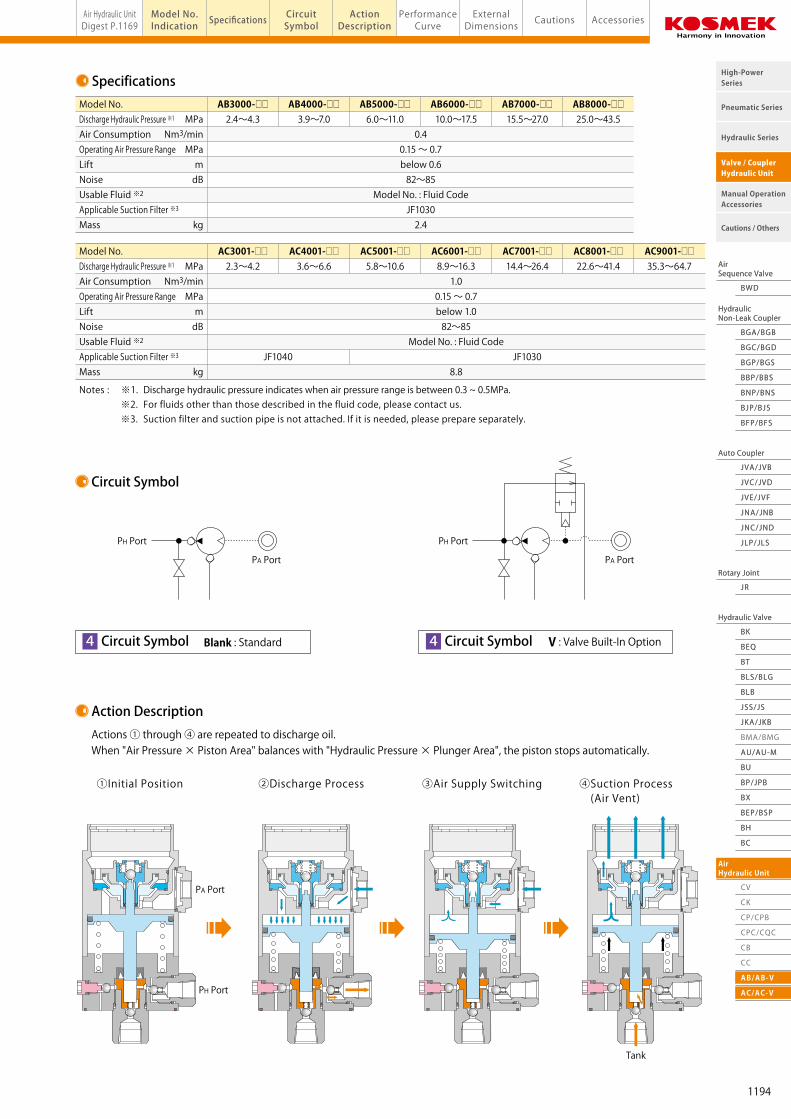
AirSequence Valve
BWD
HydraulicNon-Leak Coupler
BGA/BGB
BGC/BGD
BGP/BGS
BBP/BBS
BNP/BNS
BJP/BJS
BFP/BFS
Auto Coupler
JVC/JVD
JVA/JVB
JVE/JVF
JNA/JNB
JNC/JND
JLP/JLS
Hydraulic Valve
BK
BEQ
BT
BLS/BLG
BLB
JSS/JS
JKA/JKB
AU/AU-M
BU
AirHydraulic Unit
CV
Rotary Joint
JR
BP/JPB
BX
BEP/BSP
BH
BC
Pneumatic Series
Hydraulic Series
Valve / CouplerHydraulic Unit
Cautions / Others
High-PowerSeries
Manual OperationAccessories
AirSequence Valve
BWD
HydraulicNon-Leak Coupler
BGA/BGB
BGC/BGD
BGP/BGS
BBP/BBS
BNP/BNS
BJP/BJS
BFP/BFS
Auto Coupler
JVC/JVD
JVA/JVB
JVE/JVF
JNA/JNB
JNC/JND
JLP/JLS
Hydraulic Valve
BK
BEQ
BT
BLS/BLG
BLB
JSS/JS
JKA/JKB
BMA/BMG
AU/AU-M
BU
AirHydraulic Unit
CV
CK
CP/CPB
CPC/CQC
CB
CC
AB/AB-V
AC/AC-V
Rotary Joint
JR
BP/JPB
BX
BEP/BSP
BH
BC
Pneumatic Series
Hydraulic Series
Valve / CouplerHydraulic Unit
Cautions / Others
High-PowerSeries
Manual OperationAccessories
Air Hydraulic UnitDigest P.1169
PerformanceCurve
ActionDescription AccessoriesExternal
Dimensions CautionsModel No.Indication Specifications Circuit
SymbolAir Hydraulic Unit AB/AC Pump model AB/AC
Model AB/AC
AB Pump / AC Pump(Air Driven Hydraulic Pump)
・Air-driven hydraulic pump to generate high-pressure hydraulic-low pressure simply by supplying compressed air.
・Variation of total 13 different sizes and flow rates.
・Applicable to explosion proof specification because no electric motor is used.
Features
Model No. Indication
1
2 4 51 3
Pump Size
AB : AB Pump (Compact Design, Air Consumption 0.4 Nm3/min)AC : AC Pump (High Volume of Flow, Air Consumption 1.0 Nm3/min)
AB 700 0 - 0
3 Design No.
0 : When AB pump is selected1 : When AC pump is selected
Revision Number
2 Pressure Range
300 : Discharge Hydraulic Pressure With AB Pump: 2.4~4.3MPa With AC Pump: 2.3~4.2MPa
400 : Discharge Hydraulic Pressure With AB Pump: 3.9~7.0MPa With AC Pump: 3.6~6.6MPa
500 : Discharge Hydraulic Pressure With AB Pump: 6.0~11.0MPa With AC Pump: 5.8~10.6MPa
600 : Discharge Hydraulic Pressure With AB Pump: 10.0~17.5MPa With AC Pump: 8.9~16.3MPa700 : Discharge Hydraulic Pressure With AB Pump: 15.5~27.0MPa With AC Pump: 14.4~26.4MPa800 : Discharge Hydraulic Pressure With AB Pump: 25.0~43.5MPa With AC Pump: 22.6~41.4MPa900 : Discharge Hydraulic Pressure No AB Pump at this range. With AC Pump: 35.3~64.7MPa
5 Usable Fluid
0 : General Hydraulic Oil (See Hydraulic Fluid List P.1237)
S : Silicon Oil
G : Water-Glycol
4 Circuit Symbol
Blank : Standard
V : Valve Built-In Option
Specifications
Circuit Symbol
Action Description
MPaNm3/min
MPamdB
kg
Model No.Discharge Hydraulic Pressure ※1
Air ConsumptionOperating Air Pressure RangeLiftNoiseUsable Fluid ※2
Applicable Suction Filter ※3
Mass
AC3001-□□ AC4001-□□ AC5001-□□ AC6001-□□ AC7001-□□ AC8001-□□ AC9001-□□ 2.3~4.2 3.6~6.6 5.8~10.6 8.9~16.3 14.4~26.4 22.6~41.4 35.3~64.7 1.0 0.15 ~ 0.7 below 1.0 82~85 Model No. : Fluid Code JF1040 JF1030 8.8
MPaNm3/min
MPamdB
kg
Model No.Discharge Hydraulic Pressure ※1
Air ConsumptionOperating Air Pressure RangeLiftNoiseUsable Fluid ※2
Applicable Suction Filter ※3
Mass
AB3000-□□ AB4000-□□ AB5000-□□ AB6000-□□ AB7000-□□ AB8000-□□ 2.4~4.3 3.9~7.0 6.0~11.0 10.0~17.5 15.5~27.0 25.0~43.5 0.4 0.15 ~ 0.7 below 0.6 82~85 Model No. : Fluid Code JF1030 2.4
Notes : ※1. Discharge hydraulic pressure indicates when air pressure range is between 0.3 ~ 0.5MPa. ※2. For fluids other than those described in the fluid code, please contact us. ※3. Suction filter and suction pipe is not attached. If it is needed, please prepare separately.
※Discharge hydraulic pressure indicates when air pressure range is between 0.3 ~ 0.5MPa.
Actions ① through ④ are repeated to discharge oil. When "Air Pressure × Piston Area" balances with "Hydraulic Pressure × Plunger Area", the piston stops automatically.
①Initial Position ②Discharge Process ③Air Supply Switching ④Suction Process (Air Vent)
PA Port
PA Port
PH Port
PH Port
Tank
4 Circuit Symbol V : Valve Built-In OptionBlank : Standard 4 Circuit Symbol
※ For fluids other than those described in the fluid code, please contact us.
PA Port
PH Port
1194
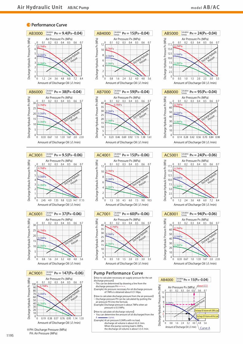
AirSequence Valve
BWD
HydraulicNon-Leak Coupler
BGA/BGB
BGC/BGD
BGP/BGS
BBP/BBS
BNP/BNS
BJP/BJS
BFP/BFS
Auto Coupler
JVC/JVD
JVA/JVB
JVE/JVF
JNA/JNB
JNC/JND
JLP/JLS
Hydraulic Valve
BK
BEQ
BT
BLS/BLG
BLB
JSS/JS
JKA/JKB
AU/AU-M
BU
AirHydraulic Unit
CV
Rotary Joint
JR
BP/JPB
BX
BEP/BSP
BH
BC
Pneumatic Series
Hydraulic Series
Valve / CouplerHydraulic Unit
Cautions / Others
High-PowerSeries
Manual OperationAccessories
AirSequence Valve
BWD
HydraulicNon-Leak Coupler
BGA/BGB
BGC/BGD
BGP/BGS
BBP/BBS
BNP/BNS
BJP/BJS
BFP/BFS
Auto Coupler
JVC/JVD
JVA/JVB
JVE/JVF
JNA/JNB
JNC/JND
JLP/JLS
Hydraulic Valve
BK
BEQ
BT
BLS/BLG
BLB
JSS/JS
JKA/JKB
BMA/BMG
AU/AU-M
BU
AirHydraulic Unit
CV
CK
CP/CPB
CPC/CQC
CB
CC
AB/AB-V
AC/AC-V
Rotary Joint
JR
BP/JPB
BX
BEP/BSP
BH
BC
Pneumatic Series
Hydraulic Series
Valve / CouplerHydraulic Unit
Cautions / Others
High-PowerSeries
Manual OperationAccessories
Air Hydraulic UnitDigest P.1169
PerformanceCurve
ActionDescription AccessoriesExternal
Dimensions CautionsModel No.Indication Specifications Circuit
SymbolAir Hydraulic Unit AB/AC Pump model AB/AC
External Dimensions
DA E
R
φL
K
N Screw
BC
F
J
Model No.ABCDEFGHJKLMNPQRSTUV
AB□0160136247088.515101355.5116460
M8×1.2513Rc1/4Rc3/8Rc1/42025Rc1/8
AC3001/4001220.5
32
Rc1/2Rc3/8
188.5
110140221317871599.595
M12×1.7518Rc1/2
3040Rc1/4
AC5001~9001213.5
25
Rc3/8Rc1/4
F
Caution (AB/AC)
Accessories (Suction Filter)
1. When using an air circuit on the incoming side of the pump, please make sure to install the air filter and regulator.
It can cause a malfunction due to dust in the piping.
2. Always use a suction filter at the pump suction side.
If you are not using Kosmek filter, we recommended using 100 or more mesh.
3. Use a pipe having no rust or scale internally as a suction pipe. Remove burrs from thread part sufficiently.
When installing apply a seal material such as seal tape to prevent air from entering.
4. AB/AC pump is not suitable for continuous operation (circulation or open circuit). Always use in a closed circuit.
Continuous operation results in packing wear, adversely affecting the pump life.
5. When installing a purchased hydraulic valve in the hydraulic circuit, the pump may not balance to stop due to internal leakage of the valve.
Continuous operation reduces the pump life. Use a non-leak valve and control valve made by Kosmek.
6. The pump discharges oil in pulses. An accumulator can be installed to reduce pulsations.
JF1030 JF1040
AC-V (Valve Built-In Option)AB-V (Valve Built-In Option)AB/AC
Machining Dimensions ofMounting Hole (Common)
Size(Refer to left drawing)
Model No. Indication
Design No.(Revision Number)
JF 103 0Rc3/8 Thread Rc1/2 Thread
D
S
H GExhaust Port
Oil Suction Port
Air Supply Port (PA Port)
Oil DischargePort(PH Port)
Air Bleed Valve
Air Bleed Port
Q
J
EK
DT
A E
φL
K
N Screw
BC
F
J
D
S
H GExhaust PortExhaust Port
Air Supply Port (PA Port)
Oil DischargePort(PH Port)
S
Oil DischargePort(PH Port)
Air Bleed Valve
Air Bleed Port
Q
JDGJ
AB
C
DT
J
Air Bleed Valve
U
V
φLAir Bleed Port
Oil Return Port
U
N Screw
Air Supply Port (PA Port)Q
3.5H
J
J
φM
30 50 30 50
φ58
φ58
Model No.
Applicable PumpPart Number
AC8001AC9001
JF1040JF1030
AC3001AC4001
2-N Thread Depth P or more
Hydraulic OilDischarge Direction
ROil Suction Port
ROil Suction Port
AB 0AC5001AC6001AC7001
VOil Return Port
Performance Curve
【How to calculate necessary air supply pressure for the set discharge pressure】・ This can be determined by drawing a line from the discharge pressure PH .(Example) Air pressure necessary for oil discharge pressure of 7MPa is obtained about 0.51 Mpa.
【How to calculate discharge pressure from the air pressure】・ Discharge pressure PH can be calculated by putting the air pressure PA into the formula.(Example) Discharge pressure is about 7MPa when air pressure is 0.51MPa.
【How to calculate oil discharge volume】・ You can determine the amount of oil discharged from the A curve.(Example) At air pressure 0.5MPa with no load, discharge oil volume is about 4.6ℓ/min. When the pump running load is 3MPa, the discharge oil volume is about 3.3ℓ/min.※PH: Discharge Pressure (MPa)
PA: Air Pressure (MPa)
※Some parts of AC pump appearance is different from this drawing.
Pump Performance Curve
PH = 24(PA-0.04)AB5000PH = 15(PA-0.04)AB4000
0
0
2.5
5.0
7.5
10.0
12.5
15.0
17.50.1 0.2 0.3 0.4 0.5 0.6 0.7
0 0.5 1.0 1.5 2.0 2.5 3.0 3.5
Air Pressure PA (MPa)
Calculation Formula
Calculation Formula
Calculation Formula
Amount of Discharge Oil (ℓ/min)
Discharge Hydraulic Pressure PH (MPa)
0
0
2
4
6
8
10
120.1 0.2 0.3 0.4 0.5 0.6 0.7
0 0.8 1.6 2.4 3.2 4.0 4.8 5.6
Air Pressure PA (MPa)
Amount of Discharge Oil (ℓ/min)
Discharge Hydraulic Pressure PH (MPa)
PH = 9.4(PA-0.04)AB3000
0
0
2
1
3
4
5
6
70.1 0.2 0.3 0.4 0.5 0.6 0.7
0 1.2 2.4 3.6 4.8 6.0 7.2 8.4
Air Pressure PA (MPa)
Amount of Discharge Oil (ℓ/min)
Discharge Hydraulic Pressure PH (MPa)
Discharge Hydraulic
Pressure
0.7MPa
0.5MPa
0.3MPaDischarge Hydraulic
Pressure
0.7MPa
0.5MPa
0.3MPa
0.7MPa
0.5MPa
0.3MPa Discharge Hydraulic
Pressure
PH = 95(PA-0.04)AB8000PH = 59(PA-0.04)AB7000
0
0
10
20
30
40
50
60
700.1 0.2 0.3 0.4 0.5 0.6 0.7
0 0.14 0.28 0.42 0.56 0.70 0.84 0.98
Air Pressure PA (MPa)
Amount of Discharge Oil (ℓ/min)
Discharge Hydraulic Pressure PH (MPa)
0
05
1510
2025
3530
400.1 0.2 0.3 0.4 0.5 0.6 0.7
0 0.23 0.46 0.69 0.92 1.15 1.38 1.61
Air Pressure PA (MPa)
Amount of Discharge Oil (ℓ/min)
Discharge Hydraulic Pressure PH (MPa)
PH = 38(PA-0.04)AB6000
0
0
5
10
15
20
25
300.1 0.2 0.3 0.4 0.5 0.6 0.7
0 0.33 0.67 1.0 1.33 1.67 2.0 2.33
Air Pressure PA (MPa)
Amount of Discharge Oil (ℓ/min)
Discharge Hydraulic Pressure PH (MPa)
Discharge Hydraulic
Pressure
0.7MPa
0.5MPa
0.3MPaDischarge Hydraulic
Pressure
0.7MPa
0.5MPa
0.3MPa
0.7MPa
0.5MPa
0.3MPa Discharge Hydraulic
Pressure
PH = 24(PA-0.06)AC5001PH = 15(PA-0.06)AC4001
0
0
2.5
5.0
7.5
10.0
12.5
15.0
17.50.1 0.2 0.3 0.4 0.5 0.6 0.7
0 1.2 2.4 3.6 4.8 6.0 7.2 8.4
Air Pressure PA (MPa)
Amount of Discharge Oil (ℓ/min)
Discharge Hydraulic Pressure PH (MPa)
0
0
2
4
6
8
10
120.1 0.2 0.3 0.4 0.5 0.6 0.7
0 1.5 3.0 4.5 6.0 7.5 9.0 10.5
Air Pressure PA (MPa)
Amount of Discharge Oil (ℓ/min)
Discharge Hydraulic Pressure PH (MPa)
PH = 9.5(PA-0.06)AC3001
0
0
2
1
3
4
5
6
70.1 0.2 0.3 0.4 0.5 0.6 0.7
0 2.45 4.9 7.35 9.8 12.25 14.7 17.15
Air Pressure PA (MPa)
Amount of Discharge Oil (ℓ/min)
Discharge Hydraulic Pressure PH (MPa)
Discharge Hydraulic
Pressure
0.7MPa
0.5MPa
0.3MPaDischarge Hydraulic
Pressure
0.7MPa
0.5MPa
0.3MPa
0.7MPa
0.5MPa
0.3MPa Discharge Hydraulic
Pressure
PH = 94(PA-0.06)AC8001PH = 60(PA-0.06)AC7001
0
0
10
20
30
40
50
60
700.1 0.2 0.3 0.4 0.5 0.6 0.7
0 0.33 0.67 1.0 1.33 1.67 2.0 2.33
Air Pressure PA (MPa)
Amount of Discharge Oil (ℓ/min)
Discharge Hydraulic Pressure PH (MPa)
0
05
1510
2025
3530
400.1 0.2 0.3 0.4 0.5 0.6 0.7
0 0.5 1.0 1.5 2.0 2.5 3.0 3.5
Air Pressure PA (MPa)
Amount of Discharge Oil (ℓ/min)
Discharge Hydraulic Pressure PH (MPa)
PH = 37(PA-0.06)AC6001
0
0
5
10
15
20
25
300.1 0.2 0.3 0.4 0.5 0.6 0.7
0 0.8 1.6 2.4 3.2 4.0 4.8 5.6
Air Pressure PA (MPa)
Amount of Discharge Oil (ℓ/min)
Discharge Hydraulic Pressure PH (MPa)
Discharge Hydraulic
Pressure
0.7MPa
0.5MPa
0.3MPaDischarge Hydraulic
Pressure
0.7MPa
0.5MPa
0.3MPa
0.7MPa
0.5MPa
0.3MPaDischarge Hydraulic
Pressure
PH = 147(PA-0.06)AC9001
0
0
5040302010
60708090100
0.1 0.2 0.3 0.4 0.5 0.6 0.7
0 0.19 0.38 0.57 0.76 0.95 1.14 1.33
Air Pressure PA (MPa)
Amount of Discharge Oil (ℓ/min)
Discharge Hydraulic Pressure PH (MPa)
0.7MPa
0.5MPa
0.3MPaDischarge Hydraulic
Pressure
PH = 15(PA-0.04)AB4000
0
0
2
4
6
87
3
10
120.1 0.2 0.3 0.4 0.5
about 0.51
Curve A
0.6 0.7
0 0.8 1.6 2.4 3.2 4.0 4.8 5.6
Air Pressure PA (MPa)
Amount of Discharge Oil (ℓ/min)
Discharge Hydraulic Pressure PH (MPa)
0.5MPa
Discharge Oil Volume with No Load
Discharge Oil Volume with 3MPa Load
Calculation Formula
Calculation Formula
Calculation Formula
Calculation Formula
Calculation Formula
Calculation Formula
Calculation Formula
Calculation Formula
Calculation Formula
Calculation Formula
Calculation Formula
Discharge Hydraulic Pressure
1195
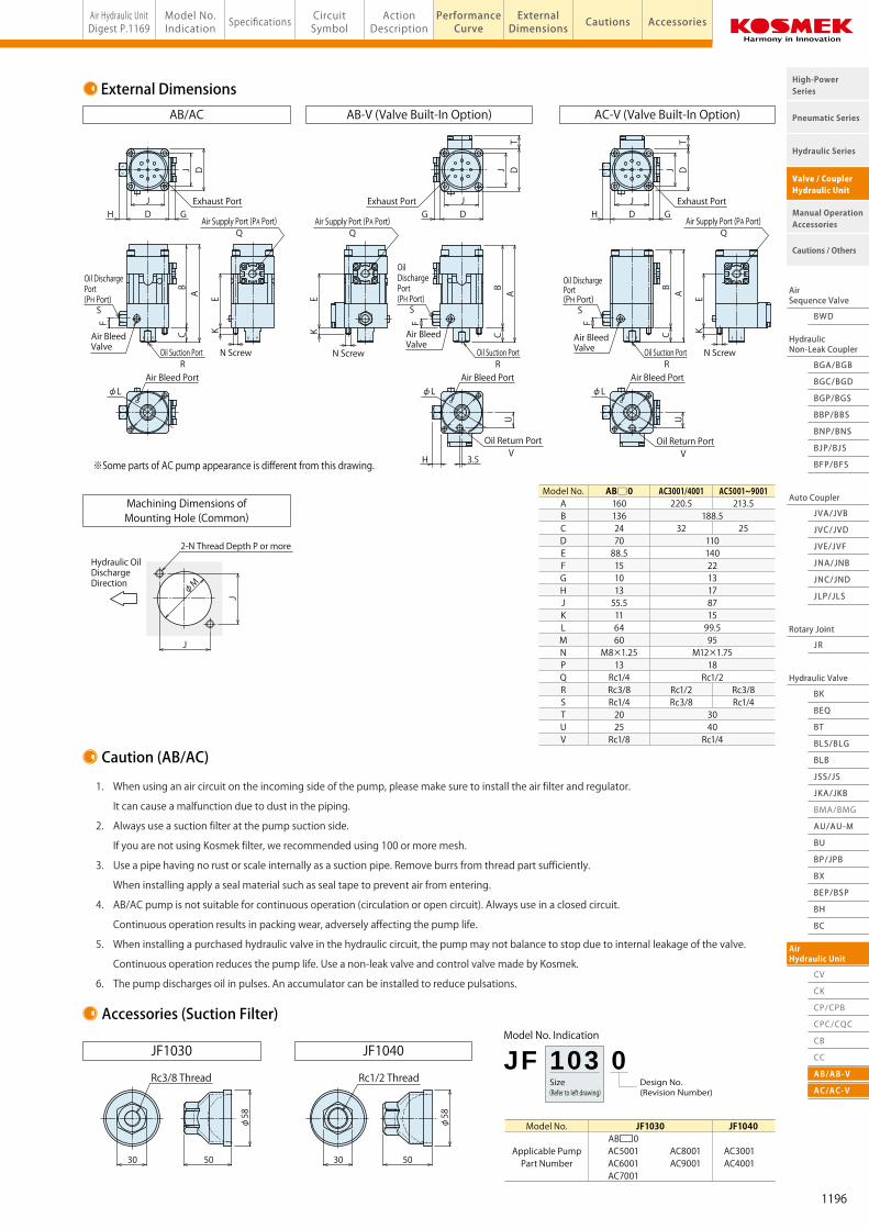
AirSequence Valve
BWD
HydraulicNon-Leak Coupler
BGA/BGB
BGC/BGD
BGP/BGS
BBP/BBS
BNP/BNS
BJP/BJS
BFP/BFS
Auto Coupler
JVC/JVD
JVA/JVB
JVE/JVF
JNA/JNB
JNC/JND
JLP/JLS
Hydraulic Valve
BK
BEQ
BT
BLS/BLG
BLB
JSS/JS
JKA/JKB
AU/AU-M
BU
AirHydraulic Unit
CV
Rotary Joint
JR
BP/JPB
BX
BEP/BSP
BH
BC
Pneumatic Series
Hydraulic Series
Valve / CouplerHydraulic Unit
Cautions / Others
High-PowerSeries
Manual OperationAccessories
AirSequence Valve
BWD
HydraulicNon-Leak Coupler
BGA/BGB
BGC/BGD
BGP/BGS
BBP/BBS
BNP/BNS
BJP/BJS
BFP/BFS
Auto Coupler
JVC/JVD
JVA/JVB
JVE/JVF
JNA/JNB
JNC/JND
JLP/JLS
Hydraulic Valve
BK
BEQ
BT
BLS/BLG
BLB
JSS/JS
JKA/JKB
BMA/BMG
AU/AU-M
BU
AirHydraulic Unit
CV
CK
CP/CPB
CPC/CQC
CB
CC
AB/AB-V
AC/AC-V
Rotary Joint
JR
BP/JPB
BX
BEP/BSP
BH
BC
Pneumatic Series
Hydraulic Series
Valve / CouplerHydraulic Unit
Cautions / Others
High-PowerSeries
Manual OperationAccessories
Air Hydraulic UnitDigest P.1169
PerformanceCurve
ActionDescription AccessoriesExternal
Dimensions CautionsModel No.Indication Specifications Circuit
SymbolAir Hydraulic Unit AB/AC Pump model AB/AC
External Dimensions
DA E
R
φL
K
N Screw
BC
F
J
Model No.ABCDEFGHJKLMNPQRSTUV
AB□0160136247088.515101355.5116460
M8×1.2513Rc1/4Rc3/8Rc1/42025Rc1/8
AC3001/4001220.5
32
Rc1/2Rc3/8
188.5
110140221317871599.595
M12×1.7518Rc1/2
3040Rc1/4
AC5001~9001213.5
25
Rc3/8Rc1/4
F
Caution (AB/AC)
Accessories (Suction Filter)
1. When using an air circuit on the incoming side of the pump, please make sure to install the air filter and regulator.
It can cause a malfunction due to dust in the piping.
2. Always use a suction filter at the pump suction side.
If you are not using Kosmek filter, we recommended using 100 or more mesh.
3. Use a pipe having no rust or scale internally as a suction pipe. Remove burrs from thread part sufficiently.
When installing apply a seal material such as seal tape to prevent air from entering.
4. AB/AC pump is not suitable for continuous operation (circulation or open circuit). Always use in a closed circuit.
Continuous operation results in packing wear, adversely affecting the pump life.
5. When installing a purchased hydraulic valve in the hydraulic circuit, the pump may not balance to stop due to internal leakage of the valve.
Continuous operation reduces the pump life. Use a non-leak valve and control valve made by Kosmek.
6. The pump discharges oil in pulses. An accumulator can be installed to reduce pulsations.
JF1030 JF1040
AC-V (Valve Built-In Option)AB-V (Valve Built-In Option)AB/AC
Machining Dimensions ofMounting Hole (Common)
Size(Refer to left drawing)
Model No. Indication
Design No.(Revision Number)
JF 103 0Rc3/8 Thread Rc1/2 Thread
D
S
H GExhaust Port
Oil Suction Port
Air Supply Port (PA Port)
Oil DischargePort(PH Port)
Air Bleed Valve
Air Bleed Port
Q
J
EK
DT
A E
φL
K
N Screw
BC
F
J
D
S
H GExhaust PortExhaust Port
Air Supply Port (PA Port)
Oil DischargePort(PH Port)
S
Oil DischargePort(PH Port)
Air Bleed Valve
Air Bleed Port
Q
JDGJ
AB
C
DT
J
Air Bleed Valve
U
V
φLAir Bleed Port
Oil Return Port
U
N Screw
Air Supply Port (PA Port)Q
3.5H
J
J
φM
30 50 30 50
φ58
φ58
Model No.
Applicable PumpPart Number
AC8001AC9001
JF1040JF1030
AC3001AC4001
2-N Thread Depth P or more
Hydraulic OilDischarge Direction
ROil Suction Port
ROil Suction Port
AB 0AC5001AC6001AC7001
VOil Return Port
Performance Curve
【How to calculate necessary air supply pressure for the set discharge pressure】・ This can be determined by drawing a line from the discharge pressure PH .(Example) Air pressure necessary for oil discharge pressure of 7MPa is obtained about 0.51 Mpa.
【How to calculate discharge pressure from the air pressure】・ Discharge pressure PH can be calculated by putting the air pressure PA into the formula.(Example) Discharge pressure is about 7MPa when air pressure is 0.51MPa.
【How to calculate oil discharge volume】・ You can determine the amount of oil discharged from the A curve.(Example) At air pressure 0.5MPa with no load, discharge oil volume is about 4.6ℓ/min. When the pump running load is 3MPa, the discharge oil volume is about 3.3ℓ/min.※PH: Discharge Pressure (MPa)
PA: Air Pressure (MPa)
※Some parts of AC pump appearance is different from this drawing.
Pump Performance Curve
PH = 24(PA-0.04)AB5000PH = 15(PA-0.04)AB4000
0
0
2.5
5.0
7.5
10.0
12.5
15.0
17.50.1 0.2 0.3 0.4 0.5 0.6 0.7
0 0.5 1.0 1.5 2.0 2.5 3.0 3.5
Air Pressure PA (MPa)
Calculation Formula
Calculation Formula
Calculation Formula
Amount of Discharge Oil (ℓ/min)
Discharge Hydraulic Pressure PH (MPa)
0
0
2
4
6
8
10
120.1 0.2 0.3 0.4 0.5 0.6 0.7
0 0.8 1.6 2.4 3.2 4.0 4.8 5.6
Air Pressure PA (MPa)
Amount of Discharge Oil (ℓ/min)
Discharge Hydraulic Pressure PH (MPa)
PH = 9.4(PA-0.04)AB3000
0
0
2
1
3
4
5
6
70.1 0.2 0.3 0.4 0.5 0.6 0.7
0 1.2 2.4 3.6 4.8 6.0 7.2 8.4
Air Pressure PA (MPa)
Amount of Discharge Oil (ℓ/min)
Discharge Hydraulic Pressure PH (MPa)
Discharge Hydraulic
Pressure
0.7MPa
0.5MPa
0.3MPaDischarge Hydraulic
Pressure
0.7MPa
0.5MPa
0.3MPa
0.7MPa
0.5MPa
0.3MPa Discharge Hydraulic
Pressure
PH = 95(PA-0.04)AB8000PH = 59(PA-0.04)AB7000
0
0
10
20
30
40
50
60
700.1 0.2 0.3 0.4 0.5 0.6 0.7
0 0.14 0.28 0.42 0.56 0.70 0.84 0.98
Air Pressure PA (MPa)
Amount of Discharge Oil (ℓ/min)
Discharge Hydraulic Pressure PH (MPa)
0
05
1510
2025
3530
400.1 0.2 0.3 0.4 0.5 0.6 0.7
0 0.23 0.46 0.69 0.92 1.15 1.38 1.61
Air Pressure PA (MPa)
Amount of Discharge Oil (ℓ/min)
Discharge Hydraulic Pressure PH (MPa)
PH = 38(PA-0.04)AB6000
0
0
5
10
15
20
25
300.1 0.2 0.3 0.4 0.5 0.6 0.7
0 0.33 0.67 1.0 1.33 1.67 2.0 2.33
Air Pressure PA (MPa)
Amount of Discharge Oil (ℓ/min)
Discharge Hydraulic Pressure PH (MPa)
Discharge Hydraulic
Pressure
0.7MPa
0.5MPa
0.3MPaDischarge Hydraulic
Pressure
0.7MPa
0.5MPa
0.3MPa
0.7MPa
0.5MPa
0.3MPa Discharge Hydraulic
Pressure
PH = 24(PA-0.06)AC5001PH = 15(PA-0.06)AC4001
0
0
2.5
5.0
7.5
10.0
12.5
15.0
17.50.1 0.2 0.3 0.4 0.5 0.6 0.7
0 1.2 2.4 3.6 4.8 6.0 7.2 8.4
Air Pressure PA (MPa)
Amount of Discharge Oil (ℓ/min)
Discharge Hydraulic Pressure PH (MPa)
0
0
2
4
6
8
10
120.1 0.2 0.3 0.4 0.5 0.6 0.7
0 1.5 3.0 4.5 6.0 7.5 9.0 10.5
Air Pressure PA (MPa)
Amount of Discharge Oil (ℓ/min)
Discharge Hydraulic Pressure PH (MPa)
PH = 9.5(PA-0.06)AC3001
0
0
2
1
3
4
5
6
70.1 0.2 0.3 0.4 0.5 0.6 0.7
0 2.45 4.9 7.35 9.8 12.25 14.7 17.15
Air Pressure PA (MPa)
Amount of Discharge Oil (ℓ/min)
Discharge Hydraulic Pressure PH (MPa)
Discharge Hydraulic
Pressure
0.7MPa
0.5MPa
0.3MPaDischarge Hydraulic
Pressure
0.7MPa
0.5MPa
0.3MPa
0.7MPa
0.5MPa
0.3MPa Discharge Hydraulic
Pressure
PH = 94(PA-0.06)AC8001PH = 60(PA-0.06)AC7001
0
0
10
20
30
40
50
60
700.1 0.2 0.3 0.4 0.5 0.6 0.7
0 0.33 0.67 1.0 1.33 1.67 2.0 2.33
Air Pressure PA (MPa)
Amount of Discharge Oil (ℓ/min)
Discharge Hydraulic Pressure PH (MPa)
0
05
1510
2025
3530
400.1 0.2 0.3 0.4 0.5 0.6 0.7
0 0.5 1.0 1.5 2.0 2.5 3.0 3.5
Air Pressure PA (MPa)
Amount of Discharge Oil (ℓ/min)
Discharge Hydraulic Pressure PH (MPa)
PH = 37(PA-0.06)AC6001
0
0
5
10
15
20
25
300.1 0.2 0.3 0.4 0.5 0.6 0.7
0 0.8 1.6 2.4 3.2 4.0 4.8 5.6
Air Pressure PA (MPa)
Amount of Discharge Oil (ℓ/min)
Discharge Hydraulic Pressure PH (MPa)
Discharge Hydraulic
Pressure
0.7MPa
0.5MPa
0.3MPaDischarge Hydraulic
Pressure
0.7MPa
0.5MPa
0.3MPa
0.7MPa
0.5MPa
0.3MPaDischarge Hydraulic
Pressure
PH = 147(PA-0.06)AC9001
0
0
5040302010
60708090100
0.1 0.2 0.3 0.4 0.5 0.6 0.7
0 0.19 0.38 0.57 0.76 0.95 1.14 1.33
Air Pressure PA (MPa)
Amount of Discharge Oil (ℓ/min)
Discharge Hydraulic Pressure PH (MPa)
0.7MPa
0.5MPa
0.3MPaDischarge Hydraulic
Pressure
PH = 15(PA-0.04)AB4000
0
0
2
4
6
87
3
10
120.1 0.2 0.3 0.4 0.5
about 0.51
Curve A
0.6 0.7
0 0.8 1.6 2.4 3.2 4.0 4.8 5.6
Air Pressure PA (MPa)
Amount of Discharge Oil (ℓ/min)
Discharge Hydraulic Pressure PH (MPa)
0.5MPa
Discharge Oil Volume with No Load
Discharge Oil Volume with 3MPa Load
Calculation Formula
Calculation Formula
Calculation Formula
Calculation Formula
Calculation Formula
Calculation Formula
Calculation Formula
Calculation Formula
Calculation Formula
Calculation Formula
Calculation Formula
Discharge Hydraulic Pressure
1196
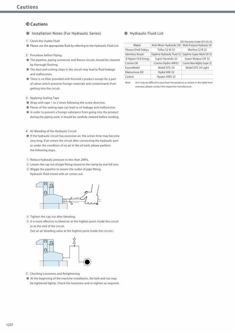
Notes on Hydraulic Cylinder Speed Control Circuit
Cautions
Installation Notes(For Hydraulic Series)
Hydraulic Fluid List
Notes on Handling
Maintenance/ Inspection
Warranty
Index
Search byAlphabetical Order
Company Profile
Sales Offices
Company Profile
Our Products
History
Pneumatic Series
Hydraulic Series
Valve / CouplerHydraulic Unit
Cautions / Others
High-PowerSeries
Manual OperationAccessories
Installation Notes(For Hydraulic Series)Installation Notes(For Hydraulic Series)
Notes on Hydraulic CylinderSpeed Control Circuit
Notes on Hydraulic CylinderSpeed Control Circuit Maintenance/Inspection WarrantyNotes on HandlingHydraulic Fluid ListHydraulic Fluid ListCautions
Cautions
● Installation Notes (For Hydraulic Series) ● Hydraulic Fluid List
1)Check the Usable Fluid
● Please use the appropriate fluid by referring to the Hydraulic Fluid List.
2)Procedure before Piping
● The pipeline, piping connector and fixture circuits should be cleaned
by thorough flushing.
● The dust and cutting chips in the circuit may lead to fluid leakage
and malfunction.
● There is no filter provided with Kosmek’s product except for a part
of valves which prevents foreign materials and contaminants from
getting into the circuit.
3)Applying Sealing Tape
● Wrap with tape 1 to 2 times following the screw direction.
● Pieces of the sealing tape can lead to oil leakage and malfunction.
● In order to prevent a foreign substance from going into the product
during the piping work, it should be carefully cleaned before working.
4)Air Bleeding of the Hydraulic Circuit
● If the hydraulic circuit has excessive air, the action time may become
very long. If air enters the circuit after connecting the hydraulic port
or under the condition of no air in the oil tank, please perform
the following steps.
① Reduce hydraulic pressure to less than 2MPa.
② Loosen the cap nut of pipe fitting closest to the clamp by one full turn.
③ Wiggle the pipeline to loosen the outlet of pipe fitting.
Hydraulic fluid mixed with air comes out.
④ Tighten the cap nut after bleeding.
⑤ It is more effective to bleed air at the highest point inside the circuit
or at the end of the circuit.
(Set an air bleeding valve at the highest point inside the circuit.)
5)Checking Looseness and Retightening
● At the beginning of the machine installation, the bolt and nut may
be tightened lightly. Check the looseness and re-tighten as required.
Showa Shell SekiyuIdemitsu KosanJX Nippon Oil & EnergyCosmo OilExxonMobilMatsumura OilCastrol
Maker Anti-Wear Hydraulic OilTellus S2 M 32
Daphne Hydraulic Fluid 32Super Hyrando 32Cosmo Hydro AW32Mobil DTE 24Hydol AW-32Hyspin AWS 32
Multi-Purpose Hydraulic OilMorlina S2 B 32
Daphne Super Multi Oil 32Super Mulpus DX 32Cosmo New Mighty Super 32Mobil DTE 24 Light
Note As it may be difficult to purchase the products as shown in the table from overseas, please contact the respective manufacturer.
ISO Viscosity Grade ISO-VG-32
Flow Control at the Release Side
W
Flow Control Valve(Any location is OK)
Sequence Valve
● Notes on Hydraulic Cylinder Speed Control Unit
Please pay attention to the cautions below. Design the hydraulic circuit for controlling the action speed of hydraulic cylinder.
Improper circuit design may lead to malfunctions and damages. Please review the circuit design in advance.! ● Flow Control Circuit for Single Acting Cylinder For spring return single acting cylinders, restricting flow during release can extremely slow down or disrupt release action. The preferred method is to control the flow during the lock action using a valve that has free-flow in the release direction. It is also preferred to provide a flow control valve at each actuator.
Accelerated clamping speed by excessive hydraulic flow to the cylinder may sustain damage. In this case add flow control to regulate flow. (Please add flow control to release flow if the lever weight is put on at the time of release action when using swing clamps.)
● Flow Control Circuit for Double Acting Cylinder Flow control circuit for double acting cylinder should have meter-out circuits for both the lock and release sides. Meter-in control can have adverse effect by presence of air in the system. However, in the case of controlling LKE, TMA, TLA, both lock side
and release side should be meter-in circuit.
Refer to P.75 for speed adjustment of LKE.
For TMA and TLA, if meter-out circuit is used, abnormal high
pressure is created, which causes oil leakage and damage.
【Meter-out Circuit】 (Except LKE/TMA/TLA)
【Meter-in Circuit】 (LKE/TMA/TLA must be controlled with meter-in.)
In the case of meter-out circuit, the hydraulic circuit should be designed with the following points. ① Single acting components should not be used in the same flow control circuit as the double acting components. The release action of the single acting cylinders may become erratic or very slow.
Refer to the following circuit when both the single acting cylinder and double acting cylinder are used together. ○ Separate the control circuit.
○ Reduce the influence of double acting cylinder control unit. However, due to the back pressure in tank line, single action cylinder is activated after double action cylinder works.
② In the case of meter-out circuit, the inner circuit pressure may increase during the cylinder action because of the fluid supply. The increase of the inner circuit pressure can be prevented by reducing the supplied fluid beforehand via the flow control valve. Especially when using sequence valve or pressure switches for clamping detection. If the back pressure is more than the set pressure then the system will not work as it is designed to.
1237

Notes on Hydraulic Cylinder Speed Control Circuit
Cautions
Installation Notes(For Hydraulic Series)
Hydraulic Fluid List
Notes on Handling
Maintenance/ Inspection
Warranty
Index
Search byAlphabetical Order
Company Profile
Sales Offices
Company Profile
Our Products
History
Pneumatic Series
Hydraulic Series
Valve / CouplerHydraulic Unit
Cautions / Others
High-PowerSeries
Manual OperationAccessories
Installation Notes(For Hydraulic Series)Installation Notes(For Hydraulic Series)
Notes on Hydraulic CylinderSpeed Control Circuit
Notes on Hydraulic CylinderSpeed Control Circuit Maintenance/Inspection WarrantyNotes on HandlingHydraulic Fluid ListHydraulic Fluid ListCautions
Cautions
● Installation Notes (For Hydraulic Series) ● Hydraulic Fluid List
1)Check the Usable Fluid
● Please use the appropriate fluid by referring to the Hydraulic Fluid List.
2)Procedure before Piping
● The pipeline, piping connector and fixture circuits should be cleaned
by thorough flushing.
● The dust and cutting chips in the circuit may lead to fluid leakage
and malfunction.
● There is no filter provided with Kosmek’s product except for a part
of valves which prevents foreign materials and contaminants from
getting into the circuit.
3)Applying Sealing Tape
● Wrap with tape 1 to 2 times following the screw direction.
● Pieces of the sealing tape can lead to oil leakage and malfunction.
● In order to prevent a foreign substance from going into the product
during the piping work, it should be carefully cleaned before working.
4)Air Bleeding of the Hydraulic Circuit
● If the hydraulic circuit has excessive air, the action time may become
very long. If air enters the circuit after connecting the hydraulic port
or under the condition of no air in the oil tank, please perform
the following steps.
① Reduce hydraulic pressure to less than 2MPa.
② Loosen the cap nut of pipe fitting closest to the clamp by one full turn.
③ Wiggle the pipeline to loosen the outlet of pipe fitting.
Hydraulic fluid mixed with air comes out.
④ Tighten the cap nut after bleeding.
⑤ It is more effective to bleed air at the highest point inside the circuit
or at the end of the circuit.
(Set an air bleeding valve at the highest point inside the circuit.)
5)Checking Looseness and Retightening
● At the beginning of the machine installation, the bolt and nut may
be tightened lightly. Check the looseness and re-tighten as required.
Showa Shell SekiyuIdemitsu KosanJX Nippon Oil & EnergyCosmo OilExxonMobilMatsumura OilCastrol
Maker Anti-Wear Hydraulic OilTellus S2 M 32
Daphne Hydraulic Fluid 32Super Hyrando 32Cosmo Hydro AW32Mobil DTE 24Hydol AW-32Hyspin AWS 32
Multi-Purpose Hydraulic OilMorlina S2 B 32
Daphne Super Multi Oil 32Super Mulpus DX 32Cosmo New Mighty Super 32Mobil DTE 24 Light
Note As it may be difficult to purchase the products as shown in the table from overseas, please contact the respective manufacturer.
ISO Viscosity Grade ISO-VG-32
Flow Control at the Release Side
W
Flow Control Valve(Any location is OK)
Sequence Valve
● Notes on Hydraulic Cylinder Speed Control Unit
Please pay attention to the cautions below. Design the hydraulic circuit for controlling the action speed of hydraulic cylinder.
Improper circuit design may lead to malfunctions and damages. Please review the circuit design in advance.! ● Flow Control Circuit for Single Acting Cylinder For spring return single acting cylinders, restricting flow during release can extremely slow down or disrupt release action. The preferred method is to control the flow during the lock action using a valve that has free-flow in the release direction. It is also preferred to provide a flow control valve at each actuator.
Accelerated clamping speed by excessive hydraulic flow to the cylinder may sustain damage. In this case add flow control to regulate flow. (Please add flow control to release flow if the lever weight is put on at the time of release action when using swing clamps.)
● Flow Control Circuit for Double Acting Cylinder Flow control circuit for double acting cylinder should have meter-out circuits for both the lock and release sides. Meter-in control can have adverse effect by presence of air in the system. However, in the case of controlling LKE, TMA, TLA, both lock side
and release side should be meter-in circuit.
Refer to P.75 for speed adjustment of LKE.
For TMA and TLA, if meter-out circuit is used, abnormal high
pressure is created, which causes oil leakage and damage.
【Meter-out Circuit】 (Except LKE/TMA/TLA)
【Meter-in Circuit】 (LKE/TMA/TLA must be controlled with meter-in.)
In the case of meter-out circuit, the hydraulic circuit should be designed with the following points. ① Single acting components should not be used in the same flow control circuit as the double acting components. The release action of the single acting cylinders may become erratic or very slow.
Refer to the following circuit when both the single acting cylinder and double acting cylinder are used together. ○ Separate the control circuit.
○ Reduce the influence of double acting cylinder control unit. However, due to the back pressure in tank line, single action cylinder is activated after double action cylinder works.
② In the case of meter-out circuit, the inner circuit pressure may increase during the cylinder action because of the fluid supply. The increase of the inner circuit pressure can be prevented by reducing the supplied fluid beforehand via the flow control valve. Especially when using sequence valve or pressure switches for clamping detection. If the back pressure is more than the set pressure then the system will not work as it is designed to.
1238
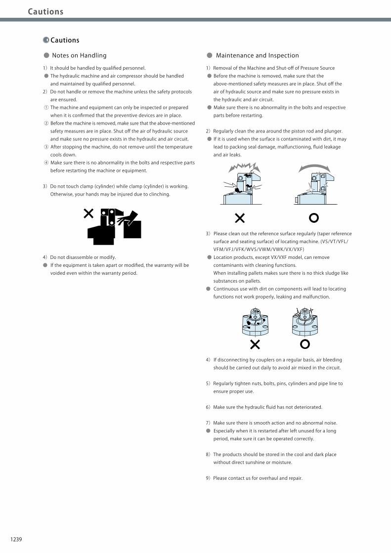
Notes on Hydraulic Cylinder Speed Control Circuit
Cautions
Installation Notes(For Hydraulic Series)
Hydraulic Fluid List
Notes on Handling
Maintenance/ Inspection
Warranty
Index
Search byAlphabetical Order
Company Profile
Sales Offices
Company Profile
Our Products
History
Pneumatic Series
Hydraulic Series
Valve / CouplerHydraulic Unit
Cautions / Others
High-PowerSeries
Manual OperationAccessories
Installation Notes(For Hydraulic Series)
Notes on Hydraulic CylinderSpeed Control Circuit Maintenance/InspectionMaintenance/Inspection WarrantyWarrantyNotes on HandlingNotes on HandlingHydraulic Fluid ListCautions
1)Warranty Period
● The product warranty period is 18 months from shipment from
our factory or 12 months from initial use, whichever is earlier.
2)Warranty Scope
● If the product is damaged or malfunctions during the warranty
period due to faulty design, materials or workmanship, we will
replace or repair the defective part at our expense.
Defects or failures caused by the following are not covered.
① If the stipulated maintenance and inspection are not carried out.
② If the product is used while it is not suitable for use based on
the operator’s judgment, resulting in defect.
③ If it is used or handled in inappropriate way by the operator.
(Including damage caused by the misconduct of the third party.)
④ If the defect is caused by reasons other than our responsibility.
⑤ If repair or modifications are carried out by anyone other than Kosmek,
or without our approval and confirmation, it will void warranty.
⑥ Other caused by natural disasters or calamities not attributable to
our company.
⑦ Parts or replacement expenses due to parts consumption and
deterioration.
(Such as rubber, plastic, seal material and some electric components.)
Damages excluding from direct result of a product defect shall be
excluded from the warranty.
● Warranty
Cautions
1)It should be handled by qualified personnel.
● The hydraulic machine and air compressor should be handled
and maintained by qualified personnel.
2)Do not handle or remove the machine unless the safety protocols
are ensured.
① The machine and equipment can only be inspected or prepared
when it is confirmed that the preventive devices are in place.
② Before the machine is removed, make sure that the above-mentioned
safety measures are in place. Shut off the air of hydraulic source
and make sure no pressure exists in the hydraulic and air circuit.
③ After stopping the machine, do not remove until the temperature
cools down.
④ Make sure there is no abnormality in the bolts and respective parts
before restarting the machine or equipment.
3)Do not touch clamp (cylinder) while clamp (cylinder) is working.
Otherwise, your hands may be injured due to clinching.
4)Do not disassemble or modify.
● If the equipment is taken apart or modified, the warranty will be
voided even within the warranty period.
1)Removal of the Machine and Shut-off of Pressure Source
● Before the machine is removed, make sure that the
above-mentioned safety measures are in place. Shut off the
air of hydraulic source and make sure no pressure exists in
the hydraulic and air circuit.
● Make sure there is no abnormality in the bolts and respective
parts before restarting.
2)Regularly clean the area around the piston rod and plunger.
● If it is used when the surface is contaminated with dirt, it may
lead to packing seal damage, malfunctioning, fluid leakage
and air leaks.
3) Please clean out the reference surface regularly (taper reference
surface and seating surface) of locating machine. (VS/VT/VFL/
VFM/VFJ/VFK/WVS/VWM/VWK/VX/VXF)
● Location products, except VX/VXF model, can remove
contaminants with cleaning functions.
When installing pallets makes sure there is no thick sludge like
substances on pallets.
● Continuous use with dirt on components will lead to locating
functions not work properly, leaking and malfunction.
4) If disconnecting by couplers on a regular basis, air bleeding
should be carried out daily to avoid air mixed in the circuit.
5)Regularly tighten nuts, bolts, pins, cylinders and pipe line to
ensure proper use.
6)Make sure the hydraulic fluid has not deteriorated.
7)Make sure there is smooth action and no abnormal noise.
● Especially when it is restarted after left unused for a long
period, make sure it can be operated correctly.
8)The products should be stored in the cool and dark place
without direct sunshine or moisture.
9)Please contact us for overhaul and repair.
● Notes on Handling ● Maintenance and Inspection
1239

Notes on Hydraulic Cylinder Speed Control Circuit
Cautions
Installation Notes(For Hydraulic Series)
Hydraulic Fluid List
Notes on Handling
Maintenance/ Inspection
Warranty
Index
Search byAlphabetical Order
Company Profile
Sales Offices
Company Profile
Our Products
History
Pneumatic Series
Hydraulic Series
Valve / CouplerHydraulic Unit
Cautions / Others
High-PowerSeries
Manual OperationAccessories
Installation Notes(For Hydraulic Series)
Notes on Hydraulic CylinderSpeed Control Circuit Maintenance/InspectionMaintenance/Inspection WarrantyWarrantyNotes on HandlingNotes on HandlingHydraulic Fluid ListCautions
1)Warranty Period
● The product warranty period is 18 months from shipment from
our factory or 12 months from initial use, whichever is earlier.
2)Warranty Scope
● If the product is damaged or malfunctions during the warranty
period due to faulty design, materials or workmanship, we will
replace or repair the defective part at our expense.
Defects or failures caused by the following are not covered.
① If the stipulated maintenance and inspection are not carried out.
② If the product is used while it is not suitable for use based on
the operator’s judgment, resulting in defect.
③ If it is used or handled in inappropriate way by the operator.
(Including damage caused by the misconduct of the third party.)
④ If the defect is caused by reasons other than our responsibility.
⑤ If repair or modifications are carried out by anyone other than Kosmek,
or without our approval and confirmation, it will void warranty.
⑥ Other caused by natural disasters or calamities not attributable to
our company.
⑦ Parts or replacement expenses due to parts consumption and
deterioration.
(Such as rubber, plastic, seal material and some electric components.)
Damages excluding from direct result of a product defect shall be
excluded from the warranty.
● Warranty
Cautions
1)It should be handled by qualified personnel.
● The hydraulic machine and air compressor should be handled
and maintained by qualified personnel.
2)Do not handle or remove the machine unless the safety protocols
are ensured.
① The machine and equipment can only be inspected or prepared
when it is confirmed that the preventive devices are in place.
② Before the machine is removed, make sure that the above-mentioned
safety measures are in place. Shut off the air of hydraulic source
and make sure no pressure exists in the hydraulic and air circuit.
③ After stopping the machine, do not remove until the temperature
cools down.
④ Make sure there is no abnormality in the bolts and respective parts
before restarting the machine or equipment.
3)Do not touch clamp (cylinder) while clamp (cylinder) is working.
Otherwise, your hands may be injured due to clinching.
4)Do not disassemble or modify.
● If the equipment is taken apart or modified, the warranty will be
voided even within the warranty period.
1)Removal of the Machine and Shut-off of Pressure Source
● Before the machine is removed, make sure that the
above-mentioned safety measures are in place. Shut off the
air of hydraulic source and make sure no pressure exists in
the hydraulic and air circuit.
● Make sure there is no abnormality in the bolts and respective
parts before restarting.
2)Regularly clean the area around the piston rod and plunger.
● If it is used when the surface is contaminated with dirt, it may
lead to packing seal damage, malfunctioning, fluid leakage
and air leaks.
3) Please clean out the reference surface regularly (taper reference
surface and seating surface) of locating machine. (VS/VT/VFL/
VFM/VFJ/VFK/WVS/VWM/VWK/VX/VXF)
● Location products, except VX/VXF model, can remove
contaminants with cleaning functions.
When installing pallets makes sure there is no thick sludge like
substances on pallets.
● Continuous use with dirt on components will lead to locating
functions not work properly, leaking and malfunction.
4) If disconnecting by couplers on a regular basis, air bleeding
should be carried out daily to avoid air mixed in the circuit.
5)Regularly tighten nuts, bolts, pins, cylinders and pipe line to
ensure proper use.
6)Make sure the hydraulic fluid has not deteriorated.
7)Make sure there is smooth action and no abnormal noise.
● Especially when it is restarted after left unused for a long
period, make sure it can be operated correctly.
8)The products should be stored in the cool and dark place
without direct sunshine or moisture.
9)Please contact us for overhaul and repair.
● Notes on Handling ● Maintenance and Inspection
1240

Company Profile
Overseas Affiliates and Sales OfficesDistributors
CanadaU.S.A.CanadaU.S.A.
EuropeEurope
Asia
BrazilBrazil
Asia
Australia
MexicoMexico
JapanChina
Taiwan
PhilippinesThailand
Japan
Korea
China
Taiwan
PhilippinesThailand
IndiaIndia
Korea
SingaporeSingaporeMalaysiaMalaysia
IndonesiaIndonesia
Global Network
Asia Detailed Map
● FOR FURTHER INFORMATION ON UNLISTED SPECIFICATIONS AND SIZES, PLEASE CALL US.● SPECIFICATIONS IN THIS CATALOG ARE SUBJECT TO CHANGE WITHOUT NOTICE.
JQA-QMA10823KOSMEK HEAD OFFICE
Sales Offices
TEL.078-991-5115 FAX.078-991-8787
Sales Offices in Japan
〒651-2241 兵庫県神戸市西区室谷2丁目1番5号
Tokyo Sales OfficeTEL.048-652-8839 FAX.048-652-8828
〒331-0815 埼玉県さいたま市北区大成町4丁目81番地
Nagoya Sales OfficeTEL.0566-74-8778 FAX.0566-74-8808
〒446-0076 愛知県安城市美園町2丁目10番地1
Fukuoka Sales OfficeTEL.092-433-0424 FAX.092-433-0426
〒812-0006 福岡県福岡市博多区上牟田1丁目8-10-101
Head OfficeOsaka Sales OfficeOverseas Sales
Japan
Overseas Sales
TEL. +81-78-991-5162 FAX. +81-78-991-8787
Sales Offices across the World
〒651-2241 兵庫県神戸市西区室谷2丁目1番5号
USA
KOSMEK(USA)LTD.
G.E.T. Inc, Phil.
TEL. +1-630-620-7650 FAX. +1-630-620-9015650 Springer Drive, Lombard, IL 60148 USA
EUROPE
KOSMEK EUROPE GmbH
TEL. +43-463-287587 FAX. +43-463-287587-20Schleppeplatz 2 9020 Klagenfurt am Wörthersee Austria
Thailand TEL. +66-2-300-5132 FAX. +66-2-300-5133 67 Soi 58, RAMA 9 Rd., Suanluang, Suanluang, Bangkok 10250, Thailand
Victoria Wave Special Economic Zone Mt. Apo Building, Brgy. 186, North Caloocan City, Metro Manila, Philippines 1427
China
考世美(上海)貿易有限公司
TEL.+86-21-54253000 FAX.+86-21-54253709
中国上海市浦东新区浦三路21弄55号银亿滨江中心601室200125
Taiwan
盈生貿易有限公司
Thailand Representative Office
Mexico TEL. +52-442-161-2347Blvd Jurica la Campana 1040, B Colonia Punta Juriquilla Queretaro, QRO 76230 MexicoKOSMEK USA Mexico Office
TEL. +886-2-82261860 FAX. +886-2-82261890
台湾新北市中和區建八路2號 16F-4(遠東世紀廣場)
Philippines TEL.+63-2-310-7286 FAX. +63-2-310-7286
P.T PANDU HYDRO PNEUMATICS Ruko Green Garden Blok Z-Ⅱ No.51 Rt.005 Rw.008 Kedoya Utara-Kebon Jeruk Jakarta Barat 11520 Indonesia
Indonesia TEL. +62-21-5818632 FAX. +62-21-5814857
16F-4, No.2, Jian Ba Rd., Zhonghe District, New Taipei City Taiwan 23511
Room601, RIVERSIDE PYRAMID No.55, Lane21, Pusan Rd, Pudong Shanghai 200125, China
KOSMEK LTD. 1-5, 2-chome, Murotani, Nishi-ku, Kobe-city, Hyogo, Japan 651-2241
KOSMEK(CHINA)LTD.
Full Life Trading Co., Ltd.
(Indonesia Exclusive Distributor)
(Philippines Exclusive Distributor)
(Taiwan Exclusive Distributor)
India
KOSMEK LTD. - INDIA
TEL.+91-9880561695F 203, Level-2, First Floor, Prestige Center Point, Cunningham Road, Bangalore -560052 India
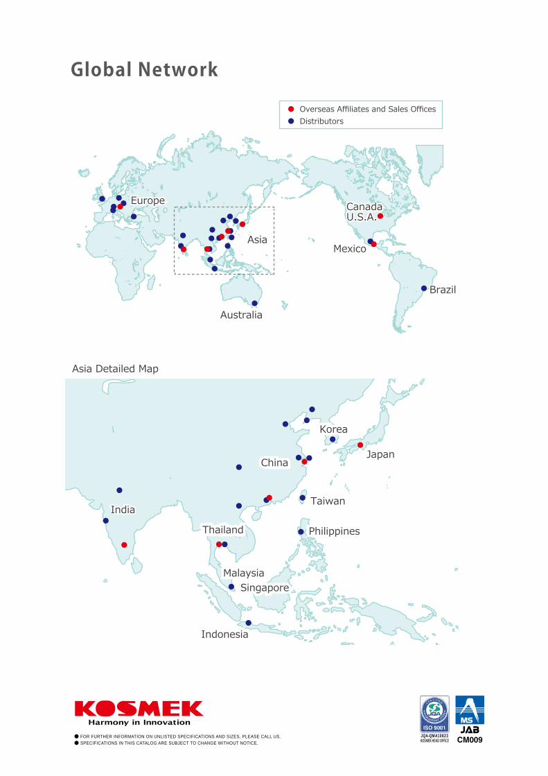