high-performance pmsm servo-drive with constrained state
TRANSCRIPT

49Bull. Pol. Ac.: Tech. 66(1) 2018
BULLETIN OF THE POLISH ACADEMY OF SCIENCES TECHNICAL SCIENCES, Vol. 66, No. 1, 2018DOI: 10.24425/119058
Abstract. This paper describes high-performance permanent magnet synchronous motor (PMSM) servo-drive with constrained state feedback (SFC) position controller. Superior behavior of the control system has been achieved by applying SFC with constraints handling method based on a posteriori model predictive approach (MPAC). The concept utilizes predictive equations obtained from discrete-time model of the PMSM to compute control signals which generate admissible values of the future state variables. The novelty of the proposed solution lies in the limitation of several state-space variables in servo-drive control system. Since MPAC has firstly been applied to limit more than one state-space variable of the plant, necessary conditions for introducing constraints into multivariable control system with SFC are depicted. Due to the low complexity of proposed algorithm, a low cost microprocessor, STM32F4, is employed to execute the state feedback position control with model predictive approach to constraints handling. Experimental results show that the proposed control method provides superior performance of PMSM servo-drive with modern SiC based voltage source inverter (VSI).
Key words: constrained control, model predictive approach, permanent magnet synchronous motor, position control, state feedback control.
High-performance PMSM servo-drive with constrained state feedback position controller
T. TARCZEWSKI1*, M. SKIWSKI1, L.J. NIEWIARA1, and L.M. GRZESIAK2
1Department of Automatics and Measurement Systems, Nicolaus Copernicus Unversity, 5 Grudziadzka St., 87-100 Toruń, Poland 2Institute of Control and Industrial Electronics, Warsaw University of Technology, 75 Koszykowa St., 00-662 Warsaw, Poland
tion algorithms such as particle swarm optimization (PSO) [11] or genetic algorithm (GA) [12] were also employed to obtain coefficients of SFC.
The task of imposing constraints into state feedback control algorithm is not easy because of relatively short time available for execution of control scheme, especially for control systems with fast dynamic response. In such a case, complex control algorithms (e.g. linear matrix inequalities) cannot be applied to solve aforementioned problem. Since the mathematical model of considered plant (i.e. PMSM fed by VSI) is well-known, methods based on model predictive approach can be employed [13]. It should be emphasized that there are two approaches to introduce constraints [14]: in the first method, boundaries are taken into account directly during designing process of con-troller, and in the second approach these are introduced a poste-riori, after designing of linear control scheme. Model predictive control (MPC) is usually applied to directly obtain constrained control in the first approach [13, 15, 16]. Despite of well-known advantages of MPC such as: robustness and elimination of mod-ulator, the main drawback of considered method is high compu-tational effort. In such a case fast processing units are required to find the solution of an optimization problem at each sampling interval [17]. For example, in [18], the finite control set model predictive control is employed for torque control of PMSM. The depicted algorithm is implemented in control system consists of a TMS320F28335 digital signal processor (DSP) and an EP1C6 FPGA. High computational effort of described control scheme causes that the sampling period is relatively long (200 µs). In [19], a TMS320LF2407 DSP is employed to execute the pre-dictive current control and the adaptive speed control of an IPMSM drive. The depicted solution consists of cascade control structure. The sampling interval of the current control loop is
1. Introduction
The permanent magnet synchronous motor (PMSM) ser-vo-drives play an essential role in high-performance applica-tions such as industrial robots and machine tools. It is caused by excellent dynamic properties, compact size and high-torque to inertia ratio [1]. Position control of PMSM servo-drive is mainly accomplished by applying series connected PI con-trollers (i.e. cascade structure) [2]. In this structure, the other control approaches, such as nonlinear control based on neural networks [1], fuzzy logic [3] or reference model [4] may also be used to obtain additional advantages of the servo-drive (e.g. ro-bustness). Since the different control loops are decoupled in the considered control scheme, the bandwidth is limited [5] and superior disturbance compensation cannot be achieved [6, 7].
An alternative method to position control of PMSM ser-vo-drive is state feedback controller (SFC). In this structure, one controller for all state-space variables is designed. The primary advantages of depicted structure are: superior distur-bance compensation [7], guaranteed robustness [8], non-lin-earity tolerance [9]. On the other hand, the main difficulties related to designing process of SFC are: determination of gain coefficients, imposing constraints for state-space variables. The first drawback is usually overcome by using trial-and-error procedure. If SFC is calculated by means of LQR approach, elements of weighting matrices may be initially chosen by ap-plying Bryson’s rule [10]. Recently, computer-aided optimiza-
*e-mail: [email protected]
Manuscript submitted 2017-10-14, revised 2018-01-07, initially accepted for publication 2018-02-03, published in February 2018.

50
T. Tarczewski, M. Skiwski, L.J. Niewiara, and L.M. Grzesiak
Bull. Pol. Ac.: Tech. 66(1) 2018
introduction of constraints into control system. Sections 5 and 6 show the experimental results and conclusion, respectively.
2. Mathematical model of the plant
In this section, a mathematical model of the plant will be de-scribed. It is necessary to perform the synthesis process of ser-vo-drive position controller. Considered electrical servo-drive consists of PMSM fed by modern VSI equipped with SiC MOSFET power devices. The following simplifying assump-tions were made during construction of the model: dynamics and nolinearities of VSI have been neglected, and dq induc-tances were assumed to be equal (Ls = Ld = Lq). Since VSI with SiC MOSFET power devices is employed, the first as-sumption is valid for a sufficiently short dead time. The second assumption is valid for non-salient PMSM.
A state equation of PMSM servo-drive non-linear model in dq rotating coordinates takes the following form [22]:
dx(t)dt
= A(ω)x(t) + Bu(t) + Ed(t), (1)
with:
A(ω) =
– Rs
Ls pω 0 0
–pω – RsLs
– pψfLs
0
0 KtJm
– BmJm
0
0 0 1 0
, x(t) =
id(t)
iq(t)
ω(t)
θ(t)
,
B =
Kp
Ls 0
0 KpLs
0 0
0 0
, E =
0
0
– 1Jm
0
, u(t) =
ud(t)
uq(t) , d(t) = Tl(t),
where: id, iq – current space vector components, Rs, Ls – resis-tance and inductance of stator, p – the number of pole pairs, ω, θ – angular speed and position of the motor shaft, Jm – moment of inertia, Kt – torque constant, Bm – viscous friction, Tl – load torque, ud, uq – space vector components of VSI control volt-ages, Kp – gain coefficient of VSI.
It should be noted that cross-coupled and non-linear terms exist in state matrix A(ωm) (1). In order to design control system with linear and stationary controller for servo-drive, lineariza-tion procedure should be performed at first. In this approach, a simple feedback linearization method previously described in [23] has been applied. Firstly, additional variables were defined:
umd(t) = pω(t)Lsiq(t)
Kp, (2)
umq(t) = pω(t)(Lsid(t) + ψf)
Kp. (3)
200 µs while the sampling interval of the speed control loop is 2 ms. In [20], the cascade control structure with predictive current control loop and predictive speed control loop with an external load estimator are designed. Due to the combination of predictive controllers with estimator, the behavior of control system is improved. The authors use a TMS320F2812 DSP for implementation of control algorithm. Similar to approaches dis-cussed above, the sampling interval is 100 µs. In the references cited above, MPC was applied for control of PMSM current (torque) or speed and current respectively. To the best of our knowledge, the only example of applying MPC in industrial PMSM servo-drive for reference position tracking is presented in [21]. In this approach, a TMS320VC33 DSP has been em-ployed, but the sampling interval equal to 100 µs seems to be insufficient for high-performance servo-drive. The demand for efficiency improvement and noise-free operation of modern servo-drives requests an application of SiC power devices in VSI. In such a case, for high switching frequency, the time available for execution of control algorithm decreases and, as a result, the low complexity, cascade-free constrained control algorithms are needed.
As it was claimed in [7], constrained state feedback control algorithm may be developed by using a two-stage design proce-dure with a posteriori introduction of constraints. Initially, the linear controller without constraints is constructed and tuned. Next, restrictions that keep control and state variables in a de-sired ranges are introduced. This guarantees low computational effort and possibility of application in control systems with sampling times below 100 µs. It should be noted that considered approach was so far applied to limit only one state variable of relatively simple control system and it cannot be directly used to impose constraints into PMSM servo-drive, where several state-space variables should be limited. Due to this, an extended solution that guarantees limitation of several state-space vari-ables in control system with state feedback controller will be introduced.
In this paper, constrained state feedback controller for high-performance PMSM servo-drive is presented. It overcomes limitations of a non-constrained SFC such as poor dynamic properties of servo-drive. The novelty of the proposed approach lies in applying a posteriori introduction of constraints into complex control system that requires limitation of several state variables. This is realized by using the discrete-time predictive model of the servo-drive to calculate boundary values of control signals that ensure admissible values of the future state-space variables. Necessary conditions for introducing constraints into multivariable control system with state feedback controller are depicted. The implementation of designed control scheme is quite easy, and is realized by a low cost STM32F407VGT6 microprocessor. Experimental results at the sampling rate of 22 kHz will demonstrate effectiveness and advantages of the proposed control method in comparison to the non-constrained SFC as well as a classical cascade control structure (CCS).
This paper is organised as follows. Section 2 develops a mathematical model of the plant and its linearization. In sec-tion 3, SFC with feedforward path for linearized and augmented model of the plant is designed. Section 4 describes a posteriori
51
High-performance PMSM servo-drive with constrained state feedback position controller
Bull. Pol. Ac.: Tech. 66(1) 2018
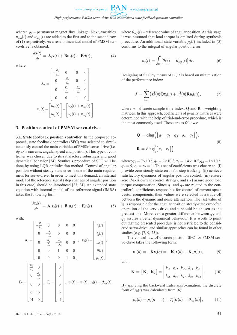
where: ψf – permanent magnet flux linkage. Next, variables umd(t) and umq(t) are added to the first and to the second row of (1) respectively. As a result, linearized model of PMSM ser-vo-drive is obtained:
dx(t)dt
= Alx(t) + Bul(t) + Ed(t), (4)
where:
Al =
– Rs
Ls 0 0 0
0 – RsLs
0 0
0 KtJm
– BmJm
0
0 0 1 0
,
ul(t) =
uld(t)
ulq(t) =
ud(t) + umd(t)
uq(t) + umq(t) .
3. Position control of PMSM servo-drive
3.1. State feedback position controller. In the proposed ap-proach, state feedback controller (SFC) was selected to simul-taneously control the main variables of PMSM servo-drive (i.e. dq axis currents, angular speed and position). This type of con-troller was chosen due to its satisfactory robustness and good dynamical behavior [24]. Synthesis procedure of SFC will be done by using LQR optimization method. Control of angular position without steady-state error is one of the main require-ment for servo-drive. In order to meet this demand, an internal model of the reference signal (step changes of angular position in this case) should be introduced [23, 24]. An extended state equation with internal model of the reference signal (IMRS) takes the following form:
dxi(t)dt
= Aixi(t) + Biui(t) + Firi(t), (5)
with:
Ai =
– Rs
Ls 0 0 0 0
0 – RsLs
0 0 0
0 KtJm
– BmJm
0 0
0 0 1 0 0
0 0 0 1 0
, xi(t) =
id(t)
iq(t)
ω(t)
θ(t)
pθ(t)
,
Bi =
Kp
Ls 0
0 KpLs
0 0
0 0
01 0
, Fi =
0
0
0
0
–1
, ui(t) = ul(t), ri(t) = θref (t).
where θref (t) – reference value of angular position. At this stage it was assumed that load torque is omitted during synthesis procedure. An additional state variable pθ(t) included in (5) conforms to the integral of angular position error:
pθ(t) = ∫0t[θ(τ) ¡ θref (τ)]dτ . (6)
Designing of SFC by means of LQR is based on minimization of the performance index:
J = t
n=0∑(xi
T(n)Qxi(n) + uiT(n)Rui(n)), (7)
where n – discrete sample time index, Q and R – weighting matrices. In this approach, coefficients of penalty matrices were determined with the help of trial-and-error procedure, which is the most commonly used. Those are as follows:
Q = diag([ q1 q2 q3 q4 q5 ]),
R = diag([ r1 r2 ]). (8)
where: q1 = 7£10–3, q2 = 9£10–4, q3 = 1.4£10–5, q4 = 1£10–2, q5 = 9, r1 = r2 = 1. This set of coefficients was chosen to: (i) provide zero steady-state error for step tracking, (ii) achieve satisfactory dynamics of angular position control, (iii) ensure zero d-axis current control strategy, and (iv) assure good load torque compensation. Since q1 and q2 are related to the con-troller’s coefficients responsible for control of current space vector components, their values were selected as a trade-off between the dynamic and noise attenuation. The last value of Q is responsible for the angular position steady-state error-free operation of the servo-drive and it should be chosen as the greatest one. Moreover, a greater difference between q5 and q4 assures a better dynamical behaviour. It is worth to point out that the presented procedure is not restricted to the consid-ered servo-drive, and similar approaches can be found in other studies (e.g. [7, 9, 25]).
The control law of discrete position SFC for PMSM ser-vo-drive takes the following form:
ui(n) = –Kxi(n) = –Kxx(n) ¡ Ke pθ(t), (9)
with:
K = [Kx Ke ] = kx1 kx2 kx3 kx4 ke1
kx5 kx6 kx7 kx8 ke2 . (10)
By applying the backward Euler approximation, the discrete form of pθ(t) was calculated from (6):
pθ(n) = pθ(n ¡ 1) + Ts [θ(n) ¡ θref (n)] , (11)

52
T. Tarczewski, M. Skiwski, L.J. Niewiara, and L.M. Grzesiak
Bull. Pol. Ac.: Tech. 66(1) 2018
where Ts – the sampling period. In order to obtain coefficients (10) of SFC, the Riccati equation should be solved [26, 27]. Its solution requires information about the state and the input matrices of the plant (5) as well as determination of penalty matrices (8). As it was stated in [27], for the solution of the linear optimal control problem with a quadratic performance index (7), the Matlab՚s lqrd command can be used. If the sufficient conditions (i.e. matrices Ai, Bi must be controllable, Q must be symmetric and positive semi-definite, R must be symmetric and positive definite) are fulfilled, a gain matrix K of optimal regulator may be obtained. Its coefficients for system described by (5) with parameters summarized in Table 1 and for penalty matrices (8) are: kx1 = 0.073, kx6 = 0.027, kx7 = 0.013, kx8 = 0.3, ke2 = 2.99, kx2 = kx3 = kx4 = ke1 = kx5 = 0.
Table 1 Selected parameters of a PMSM servo-drive
Symbol Value Unit Symbol Value Unit
PN 1.73 kW Jm 8.62£10–3 kgm2
IN 5.8 A Bm 1.4£10–2 Nms/rad
p 3 Udc 200 V
Rs 1.05 Ω Kp 100
Ls 12.68 mH fPWM 22 kHz
Kt 1.14 Nm/A Ts 45.(45) µs
3.2. Feedforward path. One of the advantages of state feed-back control is the ability to analytical calculate of feedforward path (FFP) [23]. Moreover, the inversion process does not lead to inappropriate form, what takes place in the transfer function approach [28]. Since control performance of PMSM servo-drive is influenced by an external load torque, it can be improved with the help of FFP [29]. On the basis of the residual model described in [23, 30], FFP was calculated and the modified con-trol law takes the following form:
ui(n) = –Kxx(n) ¡ K f d(n) ¡ Ke pθ(n) , (12)
where:
K f = [Kx In]G–1E =
kf 1
kf 2 ,
with: G = [A B], In – the identity matrix of appropriate di-mension. The coefficients obtained for control system (5) with parameters summarized in Table 1 and gain matrix Kx are: kf 1 = 0, kf 2 = –0.033. It should be noted that FFP acts only on the q-axis.
Since information about non-measurable load torque is required for the feedforward path, Luenberger observer will be employed to estimate its actual value. The observer was designed according to the information depicted in [23], respec-tively. Its gain matrix was calculated by using a pole placement technique. A trade-off between bandwidth and noise rejection has been taken into account during poles selection.
4. Introducing constraints
In this section, constraints will be derived on the basis of math-ematical model of the plant. This problem may be solved with MPC (e.g. [15, 16]). However, real time minimization of the objective function is quite complex and cannot be employed for a system with fast dynamics. The switching frequency for considered servo-drive with SiC power devices is relatively high and the time available for execution of control algorithm is short (i.e. Ts/2 = 22.(72) µs in this case). Because of this, complex control schemes such as MPC cannot be employed to cope with constraints in considered control system. In such a case, a posteriori introduction of constraints into system with previously designed controller seems to be an alternative solu-tion. In this framework, constraints of control and state vari-ables are initially omitted during synthesis process of the linear controller. Boundaries are calculated from predictive equations and added a posteriori to keep selected variables in a desired ranges. Aforementioned approach was firstly described in [7] and employed to limit only one state variable of relatively simple control system. In a case of position control of PMSM servo-drive, it is crucial to impose constraints on the q-axis current and on the angular velocity to keep these in accept-able ranges. Moreover, control signal in q-axis should also be restricted to ensure the linear range of the modulator. In this paper we extend solution proposed in [7] to limit more than one state variable and one output variable. Necessary conditions for introducing constraints into multivariable control system with state feedback controller will be depicted.
In order to impose constraints into considered control system, the following voltage equation will be employed:
uq(t) = Ls
diq(t)dt
+ Rsiq(t) + eq(t)/Kp , (13)
where: eq(t) = pω(t)(Lsid(t) + ψf) – the back-EMF space vector component. Next, by employing zero-order hold discretization method to (13) with a sampling period τi, the following dis-crete-time predictive formula can be obtained [31]:
uq(n) = iq(n + 1)βKp
¡ αiq(n)βKp
+ eq(n)Kp
, (14)
where: α = e–τiRs/Ls, β = 1Rs
(1 ¡ α). On the basis of (14), the upper and the lower values of the q-axis voltage that will limit the q-axis current iq(n + 1) to admissible level are calculated:
uqup(n) = sat[iqup(n + 1)]
βKp ¡
αiq(n)βKp
+ eq(n)Kp
, (15)
uqdown(n) = sat[iqdown(n + 1)]
βKp ¡
αiq(n)βKp
+ eq(n)Kp
, (16)
where: uqup(n), uqdown(n) – the upper and the lower value of q-axis voltage, sat[iqup(n + 1)], sat[iqdown(n + 1)] – saturation

53
High-performance PMSM servo-drive with constrained state feedback position controller
Bull. Pol. Ac.: Tech. 66(1) 2018
that ranges the upper and the lower values of the predicted q-axis current between §In, respectively. Values of iqup(n + 1) and iqdown(n + 1) used in saturation function in (15), and in (16) are calculated from the mechanical equation:
iq(t) = Jm
dω(t)dt
+ Bmω(t) + Tl(t)/Kt , (17)
Next, by applying zero-order hold discretization method with a sampling period τω, the following discrete-time predictive formula can be achieved [31]:
iq(n) = ω(n + 1)δKt
¡ γω(n)δKt
+ Tl(n)
Kt, (18)
where: γ = e–τωBm/Jm, δ = 1Bm
(1 ¡ γ). On the basis of (18), the upper and the lower values of the q-axis current needed for: (i) limitation of the angular velocity, (ii) saturation function in (15) and in (16) are calculated as follows:
iqup(n) = ω(n + 1)δKt
¡ γω(n)δKt
+ T l(n)Kt
, (19)
iqdown(n) = –ω(n + 1)δKt
¡ γω(n)δKt
+ T l(n)
Kt, (20)
where: iqup(n) and iqdown(n) – the upper and the lower value of q-axis current, ω(n + 1) = ωN – the boundary value of an-gular velocity, T l(n) – estimated value of the load torque. In this approach it is assumed that the boundary value of angular velocity is a priori known and it remains constant. Value of the load torque may be obtained by using Luenberger observer [23]. Although the actual values (i.e. for n) of the q-axis current constraints are calculated from (19) and (20), these may be used in (15) and (16) instead of predicted ones (i.e. for n + 1), if ω(n) and T l(n) vary slowly, what, in practice, occurs for a sufficiently high sampling rate.
The proper limitation of selected state variables requires se-lection the appropriate sampling periods (i.e. τi and τω ) needed for discretization of predictive formulas (15), (16) and (19), (20), respectively. Considered periods, in general, larger than the sampling period Ts applied for discretization of (11), may be treated as an equivalent of prediction horizon used in MPC. These values should be selected empirically, to provide optimal trajectory (i.e. compromise between overshoot and undershoot) of limited state-space variable. Selection process of the τi sam-pling period is shown in Fig. 1a while the sampling period τω is chosen on the basis of Fig. 1b. From Fig. 1 it can be seen that if value of the sampling period is too small, the overshoot of considered state variable will occur. On the other hand, a large value of the sampling period will result in the deterioration of dynamic behavior.
In the proposed method, the control signal uq(n) (i.e. sum of decoupling umq(n) and controller ulq(n)) signals is restricted by uqup(n) and uqdown(n) values obtained from (15) and (16) equations in each sampling period. In order to achieve the linear
range of the modulator operation, the q-axis control signal is further limited to §1. Values of iqup(n) and iqdown(n) are com-puted from (19) and (20) in order to maintain the angular speed of PMSM servo-drive in a range of h–ωN; ωNi. Next, on the basis of saturated values of iqup(n) and iqdown(n), constraints of control signal are calculated. This guarantees that all important state-space variables of servo-drive (i.e. the angular speed and the q-axis current) as well as the q-axis control signal will be limited. On the basis of four predictive equations with two em-pirically selected sampling periods, two state-space variables and one control variable of multivariable control system with state feedback controller will be restricted.
The proposed solution can be easily extended to limit the next state-space variables. In such a case, the predictive equa-tions that will keep considered variable between the lower and the upper value should be constructed from the model of the plant. An additional sampling period that assures the desired trajectory of a state-space variable in neighbourhood of a con-straint should also be chosen. Further requirements, such as the controllability and the possibility of estimation external disturbances (the back-EMF and the load torque in this par-ticular case) should also be satisfied to a posteriori introduce constraints into control system.
Considered constrained control system consists of SFC with IMRS (an integral path in this case). In such a case the well-known windup phenomenon may occur. In order to avoid perfor-mance deterioration (e.g. long settling time and overshoot), the anti-windup method has been employed [32]. In this approach, input signal of integrator is modified by the difference between saturated and unsaturated control signals. A modified expression of IMRS that includes anti-windup path is as follows:
pθ(n) = pθ(n ¡ 1) + Ts [θ(n) ¡ θref (n) ¡ kawuaw(n)], (21)
where: kaw – empirically selected anti-windup coefficient, uaw(n) – difference between unconstrained and constrained control signal. In a case of d-axis control signal ud(n), linear range of modulator operation is only taken into account. Since zero d-axis current is maintained, there is no need to apply
Fig. 1. Selection process of sampling periods: a) simulation responses of the q-axis current for different values of τi, b) simulation responses
of the angular velocity for different values of τω
a)
b)

54
T. Tarczewski, M. Skiwski, L.J. Niewiara, and L.M. Grzesiak
Bull. Pol. Ac.: Tech. 66(1) 2018
MPAC as well as anti-windup path. Block diagram of proposed control scheme with SFC, FFP, MPAC, and with anti-windup path is given in Fig. 2. It should be noted that only non-zero co-efficients has been shown. The flowchart of the proposed control
algorithm based on SFC with MPAC is illustrated in Fig. 3 while the block scheme of developed control system is shown in Fig. 4.
5. Experimental validation
The proposed control scheme was experimentally validated on a prototype PMSM servo-drive. Shown in Fig. 5 laboratory setup consists of two PMSM servo-drives. As a main motor, 1.73 kW PMSM (LTi Drives LST-127‒2‒30‒560) equipped with single-turn absolute encoder (Sick Stegmann SRS 50) is used. This PMSM is supplied by a prototype VSI with SiC power devices (Cree CCS020M12CM2) and with dedicated six channel gate driver (Cree CGD15FB45P1). The designed control algorithm along with SVM has been implemented in
Fig. 5. Block scheme of laboratory setupFig. 3. Flowchart of proposed control algorithm with MPAC
Fig. 4. Block diagram of PMSM servo-drive with SFC-MPAC
Fig. 2. Block diagram of proposed control scheme with SFC, FFP, MPAC, and anti-windup
55
High-performance PMSM servo-drive with constrained state feedback position controller
Bull. Pol. Ac.: Tech. 66(1) 2018
microcontroller with ARM Cortex-M4 core (STMicroelec-tronic STM32F407VGT6). The switching frequency of PWM was set at 22 kHz. As a current and voltage sensors LTS15NP and LV25P manufactured by LEM were employed. The con-ditioning and control interface consists of: encoder interface, measurement chains for phase currents and DC-link voltage, and SiC driver. The second PMSM servo-drive (commercial 3.3 kW PMSM fed by Unidrive SP1405 from Control Tech-niques) runs in a torque control mode and it is used to produce load torque. A photos of laboratory setup are presented in Fig. 6.
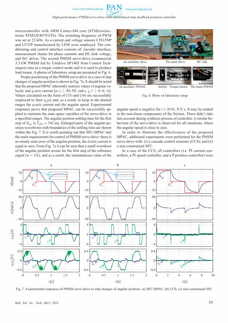
Proper positioning of the PMSM servo-drive in a case of step changes of angular position is shown in Fig. 7a. It should be noted that the proposed MPAC inherently restricts values of angular ve-locity and q-axis current (ω 2 h–50; 50i rad/s, iq 2 h–4; 4i A). Values calculated on the basis of (15) and (16) are successfully employed to limit uq(n) and, as a result, to keep in the desired ranges the q-axis current and the angular speed. Experimental responses prove that proposed MPAC can be successfully ap-plied to maintain the state-space variables of the servo-drive in a specified ranges. The angular position settling time for the first step of θref is Ts2% = 342 ms. Enlarged parts of the angular po-sition waveforms with boundaries of the settling time are shown within the Fig. 7. It is worth pointing out that SFC-MPAC met the main requirements for control of PMSM servo-drive: there is no steady-state error of the angular position, the d-axis current is equal to zero. From Fig. 7a it can be seen that a small overshoot of the angular position occurs for the first step of the reference signal (κ = 1%), and as a result, the instantaneous value of the
angular speed is negative for t 2 (0.41, 0.5) s. It may be related to the non-linear components of the friction. These didn’t take into account during synthesis process of controller. A similar be-haviour of the servo-drive is observed for all situations, where the angular speed is close to zero.
In order to illustrate the effectiveness of the proposed MPAC, additional experiments were performed for the PMSM servo-drive with: (i) a cascade control structure (CCS), and (ii) a non-constrained SFC.
In a case of the CCS, all controllers (i.e. PI current con-trollers, a PI speed controller, and a P position controller) were
Fig. 7. Experimental responses of PMSM servo-drive to step changes of angular position: (a) SFC-MPAC, (b) CCS, (c) non-constrained SFC
Fig. 6. Photo of laboratory setup
t [s] t [s] t [s]
θ[ ra
d]ω
[ rad/
s]i d
i q[ A
]u d
u q[ V
]
0 0.5 1 1.5 2
10
50
0
0
–10
–504
0.4
0
0
–4
–0.40 0.5 1 1.5 2
10
50
0
0
–10
–504
0.4
0
0
–4
–0.40 2 4 6 8 10
10
50
0
0
–10
–504
0.4
0
0
–4
–0.4
a b c
56
T. Tarczewski, M. Skiwski, L.J. Niewiara, and L.M. Grzesiak
Bull. Pol. Ac.: Tech. 66(1) 2018
tuned to achieve suitable trade-offs between bandwidth and noise of respective control loops. It was also assumed that the q-axis current component and the angular speed shouldn’t ex-ceed rated values. From Fig. 7b it can be seen that the CCS has similar behaviour to SFC-MPAC. The angular position settling time for the first step of θref is about 5% smaller in comparison to SFC-MPAC (Ts2% = 324 ms). As in a case of SFC-MPAC, a small negative value of the angular speed is observed for the angular position almost equal to its reference value. In such a case, little overshoot of θ exists (κ = 0.1%). Since the speed control loop is equipped with an integral path, aforementioned speed fluctuation is quickly compensated. It is worth to point out that, the more rapid changes of the angular speed in the neighbourhood of 0 rad/s are observed for CCS than for SFC-MPAC. In such a case, it is expected that by using SFC-MPAC, the negative impact of rapid ω changes on mechanical parts of a driven machine may be decreased.
In a case of non-constrained SFC, gain matrices (8) were modified to keep the angular speed and the q-axis current in desired ranges (i.e. ω 2 h–50; 50i rad/s, iq 2 h–4; 4i A) without MPAC. These are as follows:
Qn = diag([ qn1 qn2 qn3 qn4 qn5 ]), Rn = R , (22)
where: qn1 = 7£10–3, qn2 = 7£10–4, qn3 = 1.4£10–5, qn4 = = 1.9£10–1, qn5 = 6.5£10–1. A new gain coefficients of re-tuned SFC with FFP obtained for weighting matrices (22) are:
Knx =
0.073 0 0 0
0 0.026 0.016 0.46 ,
KTne = [ 0 0.8 ], KT
nf = [ 0 –0.032 ].
(23)
Experimental results for the servo-drive with re-tuned non-con-strained controller are presented in Fig. 7c. Note that depicted experiment has been conducted in a different time scale (5 times longer) in comparison to SFC-MPAC and to CCS due to a much longer settling time obtained for non-constrained SFC. The an-gular position settling time for the first step of θref is 6 times longer (Ts2% = 2.15 s) in comparison to SFC-MPAC. Although the angular speed and the q-axis current are in desired ranges, dynamic properties of servo-drive are poor in comparison to SFC-MPAC and to CCS.
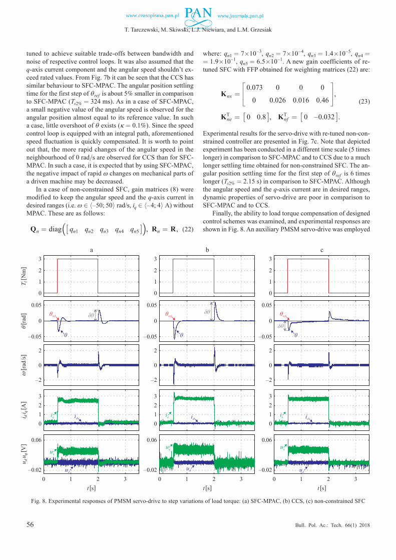
Finally, the ability to load torque compensation of designed control schemes was examined, and experimental responses are shown in Fig. 8. An auxiliary PMSM servo-drive was employed
Fig. 8. Experimental responses of PMSM servo-drive to step variations of load torque: (a) SFC-MPAC, (b) CCS, (c) non-constrained SFC
T l[ N
m]
θ[ ra
d]ω
[ rad/
s]i d
i q[ A
]u d
u q[ V
]
0
3
3
0.06
0.05
2
2
2
0
0
1
1
0
0
–0.02
–0.05
–2
1 2 3
a
t [s]
3
3
0.06
0.05
2
2
2
0
0
1
1
0
0
–0.02
–0.05
–2
0 1 2 3
b
t [s]
3
3
0.06
0.05
2
2
2
0
0
1
1
0
0
–0.02
–0.05
–2
0 1 2 3
c
t [s]
57
High-performance PMSM servo-drive with constrained state feedback position controller
Bull. Pol. Ac.: Tech. 66(1) 2018
to impose load torque on the primary PMSM shaft (Tl = 3 Nm for t 2 (0.5; 2) s and Tl = 0 Nm for the rest time of experiment). From Fig. 8a it can be seen that a better disturbance compensa-tion is obtained for SFC-MPAC in comparison CCS (Fig. 8b). Maximum values of the angular position error caused by the load torque variations are: δθ = 0.035 rad for SFC-MPAC, and δθ = 0.058 rad for CCS, respectively. It is caused by a cas-cade-free structure of SFC-MPAC as well as the application of FFP. In such a case, a very rapid compensation of Tl is observed. In a case of non-constrained SFC, the maximum value of the angular position error (δθ = 0.03 rad) is similar to SFC-MPAC, but the time needed for the disturbance compensation is longer than in other cases. It is related to application of re-tuned coef-ficients (23) for non-constrained SFC. Although similar distur-bance compensation is observed for the SFC-MPAC and for the non-constrained SFC, the latter one has very poor dynamical behaviour for step changes of angular position (Fig. 7c) and its application in a high-performance servo-drive seems to be pointless. Depicted results confirm that by using SFC-MPAC a high-performance operation of the PMSM servo-drive may be obtained.
Since 4 predictive equations described in section 4 have to be implemented (i.e. (15, 16, 19, 20)), proposed MPAC is more complex in comparison to non-constrained SFC. The time re-quired for execution of analysed control algorithms was also investigated. For 168 MHz frequency of microprocessor core, an execution time (ET) for SFC-MPAC is 9.76 µs, while for non-constrained SFC is 9.05 µs, and for CCS is 9.33 µs. De-picted execution times take into account an overall code re-quired for proper operation of servo-drive (e.g. A/D conver-sions, SVM calculation, communication with host PC, evalua-tion of control law with decoupling and load torque estimation). The obtained value of ET for SFC-MPAC clearly indicates that the proposed approach can be applied in control systems with short time allowed for execution of algorithm.
6. Conclusion
In this paper, constrained state feedback controller for high-per-formance PMSM servo-drive has been presented. The devel-oped control algorithm is based on 4 predictive equations ob-tained from discrete-time model of the PMSM. The major con-tributions of this paper are twofold. First, MPAC is presented to cope with the constraints of complex multivariable control system that requires limitation of several state-space variables. Selection of sampling intervals which assure the desired trajec-tory of state-space variables in neighbourhood of constraints is shown. Further requirements, such as the controllability and the possibility of estimation external disturbances (the back-EMF and the load torque in this particular case) to a posteriori intro-duce constraints into control system are also depicted. Secondly, a constrained state feedback position controller improves the transient and the load disturbance responses, and guarantees high-perfomance operation of the PMSM servo-drive.
The computational effort of constrained state feedback con-troller is relatively low, so it can be successfully implemented
in a low cost microprocessors. The measured execution time of an overall code is less than 10 µs. As a result, the proposed con-strained control scheme overcomes the limitation of complex algorithms and it can be employed in modern VSIs with SiC MOSFET power devices that allow high switching frequencies and low switching losses. It provides noise-free and high-per-formance operation of servo-drive.
The potential of proposed control scheme was confirmed in experimental tests and compared with CCS and non-con-strained SFC. A similar dynamical behaviour and a better dis-turbance compensation of the SFC-MPAC in comparison to the CCS causes that the proposed solution seems to a promising approach for applications where: (i) rapid disturbance compen-sation is required, (ii) sharp changes of the angular speed are not allowed, (iii) CCS cannot be employed.
References [1] F.F.M. El-Sousy, “Intelligent optimal recurrent wavelet Elman
neural network control system for permanent-magnet synchro-nous motor servo drive”, IEEE Trans. Ind. Informat. 9 (4), 1986–2003, (2013).
[2] S.M. Yang and K.W. Lin, “Automatic control loop tuning for permanent-magnet AC servo motor drives”, IEEE Trans. Ind. Electron. 63 (3), 1499–1506, (2016).
[3] H. Chaoui, M. Khayamy, and A.A. Aljarboua, “Adaptive interval type-2 fuzzy logic control for pmsm drives with a modified ref-erence frame”, IEEE Trans. Ind. Electron. 64 (5), 3786–3797, (2017).
[4] K. Urbanski, “A new sensorless speed control structure for PMSM using reference model”, Bull. Pol. Ac.: Tech. 65 (4), 489–496, (2017).
[5] M. Preindl and S. Bolognani, “Model predictive direct speed control with finite control set of PMSM drive systems”, IEEE Trans. Power Electron. 28 (2), 1007–1015, (2013).
[6] M. Bouheraoua, J. Wang, and K. Atallah, “Design and implemen-tation of an observer-based state feedback controller for a pseudo direct drive”, IET Electr. Power Appl. 7 (8), 643–653, (2013).
[7] T. Tarczewski and L.M. Grzesiak, “Constrained state feedback speed control of PMSM based on model predictive approach”, IEEE Trans. Ind. Electron. 63 (6), 3867–3875, (2016).
[8] A. Królikowski and D. Horla, “Robustness of adaptive discrete-time LQG control for first-order systems”, Bull. Pol. Ac.: Tech. 58 (1), 89–97, (2010).
[9] M. Brasel, “A gain-scheduled multivariable LQR controller for permanent magnet synchronous motor”, in Proc. IEEE MMAR Conf., 722–725, (2014).
[10] G.F. Franklin, J.D. Powell, and M.L. Workman, Digital Control of Dynamic Systems, Addison-Wesley, (1998).
[11] B. Ufnalski, A. Kaszewski, and L.M. Grzesiak, “Particle swarm optimization of the multioscillatory LQR for a three-phase four-wire voltage-source inverter with an LC output filter”, IEEE Trans. Ind. Electron. 62 (1), pp. 484–493, (2015).
[12] I. Robandi, K. Nishimori, and R. Nishimura, “Optimal feedback control design using genetic algorithm in multimachine power system”, Int. J. Elec. Power & En. Sys. 23 (4), 263–271, (2001).
[13] F. Morel, X.F. Lin-Shi, and J.M. Retif, “A comparative study of predictive current control schemes for a permanent-magnet synchronous machine drive”, IEEE Trans. Ind. Electron. 56 (7), 2715–2728, (2009).

58
T. Tarczewski, M. Skiwski, L.J. Niewiara, and L.M. Grzesiak
Bull. Pol. Ac.: Tech. 66(1) 2018
[14] F. Blanchini and S. Miani, Set-Theoretic Methods in Control, Springer Science, (2007).
[15] P.J. Serkies, “Predictive speed control in PMSM servo drive with elastic coupling at different blocking controls technique”, Prze-glad Elektrotechniczny 91 (11), 271‒274, (2015) in Polish.
[16] A. Damiano, G. Gatto, and I. Marongiu, “Operating constraints management of a surface-mounted pm synchronous machine by means of an FPGA-based model predictive control algorithm”, IEEE Trans. Ind. Informat. 10 (1), 243–255, (2014).
[17] H. Liu and S. Li, “Speed control for PMSM servo system using predictive functional control and extended state observer”, IEEE Trans. Ind. Electron. 59 (2), 1171–1183, (2012).
[18] C. Xia, X. Qiu, Z. Wang, and T. Shi, “Predictive torque con-trol for voltage source inverter-permanent magnet synchronous motor based on equal torque effect”, IET Electr. Power Appl. 10 (3), 208–216, (2016).
[19] Y. Chen, T.H. Liu, and C.F. Hsiao, “Implementation of adaptive inverse controller for an interior permanent magnet synchronous motor adjustable speed drive system based on predictive current control”, IET Electr. Power Appl. 9 (1), 60–70, (2015).
[20] J.L. Chen and T.H. Liu, “Implementation of a predictive con-troller for a sensorless interior permanent-magnet synchronous motor drive system”, IET Electr. Power Appl. 6 (8), 513–525, (2012).
[21] M.A. Stephens, C. Manzie, and M.C. Good, “Model predictive control for reference tracking on an industrial machine tool servo drive”, IEEE Trans. Ind. Informat. 9 (2), 808–816, (2013).
[22] K.Y. Chen, “Sliding mode minimum-energy control for a mecha-tronic motor-table system”, IEEE/ASME Trans. on Mechatronics 21 (3), 1487–1495, (2016).
[23] L.M. Grzesiak and T. Tarczewski, “PMSM servo-drive control system with a state feedback and a load torque feedforward com-pensation”, COMPEL 32 (1), 364–382, (2013).
[24] T. Baumgartner and J.W. Kolar, “Multivariable state feedback control of a 500 000-r/min self-bearing permanent-magnet motor”, IEEE/ASME Trans. Mechatronics 20 (3), 1149–1159, (2015).
[25] T. Tarczewski, L. Niewiara, M. Skiwski, and L. Grzesiak, “Gain-scheduled constrained state feedback control of DCDC buck power converter”, IET Power Electron., accepted manu-script, 1–9, DOI: 10.1049/iet-pel.2017.0370, (2017).
[26] F. Borrelli and T. Keviczky, “Distributed LQR design for iden-tical dynamically decoupled systems”, IEEE Trans. Autom. Con-trol 53 (8), 1901–1912, (2008).
[27] A. Tewari, Modern Control Design with Matlab and Simulink, John Wiley and Sons, (2002).
[28] H.S. Lee and M. Tomizuka, “Robust motion controller design for high-accuracy positioning systems”, IEEE Trans. Ind. Electron. 43 (1), 48–55, (1996).
[29] K. Jezernik and M. Rodic, “High precision motion control of servo drives”, IEEE Trans. Ind. Electron. 56 (10), 3810–3816, (2009).
[30] D.C. Lee, S.K. Sul., and M.H. Park, “High performance current regulator for a field-oriented controlled induction motor drive”, IEEE Trans. Ind. Appl. 30 (5), 1247–1257, (1994).
[31] P. Cortes, M.P. Kazmierkowski, and R. Kennel, “Predictive con-trol in power electronics and drives”, IEEE Trans. Ind. Electron. 55 (12), 4312–4324, (2008).
[32] H.-B. Shin and J.-G. Park, “Anti-windup PID controller with integral state predictor for variable-speed motor drives”, IEEE Trans. Ind. Electron. 59 (3), 1509–1516, (2012).