high-performance dsp hearing aid amplifier -...
TRANSCRIPT

High-Performance DSP Hearing Aid Amplifier
THe lATeST innovATion from
High-Performance DSP Hearing Aid Amplifier
Moving the open ITC marketplace forward.
Introducing IntriCon’s latest innovation — the Overtus™ high performance
8-channel digital amplifier. The Overtus™ features our new Reliant™ CLEAR
feedback manager and the all-new Acous-TAP™ acoustic push button.
These unique features make the Overtus™ the perfect choice to address
the emerging open ITC marketplace.
The Reliant™ CLEAR feedback manager is the 5th generation of Adaptive
Feedback Cancellers from IntriCon and is optimized to handle the challenges
of a short feedback path associated with open ITC devices.
The modern Acous-TAP™ acoustic push button switch allows for added user
comfort. Activated by a tap on the ear, the user can quickly and efficiently
switch user programs. The Acous-TAP™ improves the user’s experience and
reduces the need for a traditional push button.
Product featUreSreliant™ CleAr Adaptive feedback Canceller • Our 5th generation of industry-leading AFC technology • Specialized design for open ITC and CIC applications — more added stable gain and faster
reaction time for these applications • If feedback oscillation does occur, the oscillation amplitude is limited
new ACoUS-TAP™ Acoustic Push Button• Switch changes programs when user pats his ear and not the hearing aid• Eliminates the physical push button, saving size and cost • Patent pending design
improved layered noise reduction™ • Our Layered Noise Reduction technology continues to be a state-of-the-art solution to
reduction of environmental noise • Twelve noise reduction bands • A more aggressive 17dB attenuation setting available for extreme noise situations • Extended frequency range of action to 7750 Hz. — more useful for open fittings
eight-channel Wide-Dynamic-range Compression with Dynamic Contrast Detection™ • Three adaptive time-constant modes to optimize WDRC performance in critical environments • Compression ratio and threshold adjustable independently in each channel • MPO output compression limiting is also adjustable independently in each channel
event Data logging • Elapsed-time clock will record the time the amplifier has been operating since it was made • Events are recorded and ‘time stamped’ • User events: Power-on events, VC change, Program change, Low Battery events • All events will be logged in a buffer available to the fitting system• Fitting system can present the data to help the dispenser understand usage patterns
Digital random noise Generator for Tinnitus Therapy • Digital generation of random noise gives a clean noise sound for masking use • Noise is injected at the input, so it can be shaped by the existing
EQ gain adjusters • Can be used in mixed-mode applications: one program for masking, and another
program for hearing aid use
improved Audiometric Tone Generator• For in-situ fitting validation
Contact information:inTriCon CorPorATion1260 Red Fox RoadSaint Paul, MN 55112FAX: 651.636.9503Tel: 651.636.9770Website: intricon.comEmail: [email protected]
In Europe:inTriCon GmBHKesselschmiedstrasse 10D-85354 Freising, GermanyTelefon: 049-8161-4804-0Telefax: 049-8161-4804-18Email: [email protected]
High-Performance DSP Hearing Aid Amplifier
Feature deScription
reliant™ CleAr Adaptive feedback Canceller (AfC) Our fourth-generation adaptive feedback canceller in this amplifier is optimized for open ITC and CIC applications. These applications have very large but short feedback paths. This canceller is designed to adapt to the large feedback levels and to use the short path characteristics to speed the adaptation time. This AFC also has an added feature to improve on the rare situations where feedback squealing does occur. An example is when an object is quickly moved very close to the ear. In these situations, the feedback oscillations that do occur have a reduced amplitude and duration. The anti-entrainment performance follows that of its well performing Ethos predecessor. The AFC is effective for feedback problems occurring in the frequency range of 750 Hz to 6750 Hz. The AFC can be enabled or disabled separately in each user memory by programming. Additional information on this feature can be found in the IntriCon technology paper available on the IntriCon web site, or from your IntriCon sales representative.
WDrC Compression with Dynamic Contrast Detection The Ethos amplifier uses unique IntriCon technology called Dynamic Contrast Detection in an 8-channel WDRC compression configuration. The transient response of the channel compressors has three modes of operation: A) BASIC mode (single time constraints), B) BASIC/FAST mode (dual time constants), and C) BASIC/FAST/REACH (three sets of time constraints). The technology is described in detail in the technology white paper titled Two-Channel WDRC Compression with Dynamic Contrast Detection (available on the IntriCon web site, or from your IntriCon sales representative). Compression thresholds settings for both channels together are 40, 45, 50, 55, 60, 65, 70 dB SPL input-referred. Compression ratios settings of each channel are 1:1, 1.05:1, 1.11:1, 1.18:1, 1.25:1, 1.33:1, 1.43:1, 1.54:1, 1.67:1, 1.82:1, 2:1, 2.22:1, 2.5:1, 2.86:1, 3.33:1, 4:1. Time constants settings are described in the technology white paper mentioned above. Compression thresholds can also be trimmer controlled. Channel crossover frequencies are at 250, 750, 1250, 1750, 2750, 3750 and 5500 Hz.
output limiting The maximum power output (MPO) of the amplifier can be limited using the compression limiter. This method of output control does not create harmonic distortion like peak clipping. In each of 8 compression channels, the MPO can be programmed to settings of Off, 0, -2, -4, -6, - 8, -10, -12, -14, -16, -18, and -20dB (relative to no limiting). The output level will not be affected by the volume control setting, since the limiter is placed right before the output stage and after the VC block.
Band Gain equalizers Twelve band gain adjusters -equalizers -are available to precisely match fitting targets. Band 1 covers the frequency 250 Hz and below. Bands 2- 8 are 500 Hz wide. Bands 9-12 are 1000 Hz wide. Center frequencies of bands are: ~100, 500, 1000, 1500, 2000, 2500, 3000, 3500, 4250, 5250, 6250, 7250 Hz. Each band has adjustable gain in 2 dB increments from 0dB to -40 dB.
input modes There are four single input modes: MIC1, MIC2, TC+, and DAI. When one of these modes is activated, the input pad by that name is active, and all other inputs are turned off. Inputs MIC1, MIC2 and TC+ have internal AC couling capacitors. Input DAI is DC coupled and usually requires an external AC coupling capacitor. One input mode is for the Digital Noise Generator source. There are three summing modes available: ‘MIC1 + DAI’, ‘MIC1 + TC+’, and ‘MIC1 + Noise Generator’. There are 3 fixed directional pattern modes that use the signals from microphones connected to inputs MIC1 and MIC2: Fixed Directional - Cardioid, Fixed Directional - Supercardioid, Fixed Directional - Hypercardioid.
Preamplifiers There are two adjustable preamplifiers to handle the four input pads. Preamplifier 0 handles the inputs MIC1 and MIC2. Preamp 1 handles inputs DAI and TC+. Each preamp gain is programmable to the settings 0, 12, 15, 18, 21, 24, 27, and 30dB. When input MIC2 is used for directional applications its preamp gain is set automatically. Overall Gain The parameter for overall gain of the amplifier is also called Matrix Gain. It is adjustable in 1dB steps from 0 to -47dB. Use this parameter to set to set the overall gain of an application, and then use the band gain adjusters to handle frequency shaping. The user VC adjustment will reduce the gain downward starting at the setting of matrix gain. It important to remember that some values of matrix gain will be too high for a particular application, and the fitting system should insure that these high values are not available at fitting time.
volume Control function A user volume control can be connected to this amplifier, and the function can be configured to match the application. By programming, the VC can be set to analog mode or disabled. The range of the VC is programmable to the settings 50dB, 40dB, 30dB, 20dB, 10dB. To create a analog volume control, a 100kohm linear-taper VC (such as IntriCon models 11, 12, 14, 25, 26, and 35) is wired with the center terminal to the VC pad, and the ends of the VC are wired to M+ and GND respectively. The VC mode should be set to analog.
low Battery Warning When the battery voltage nears the end of life, the amplifier will detect this condition and provide a low battery warning signal. The first warnings begin when the average battery voltage falls below 1.05V. At this time, the amplifier emits three sets of double beeps every 10 minutes. When the average battery voltage falls lower than 0.95V, the amplifier issues six sets of double beeps, and then shuts down the audio output of the hearing aid. The frequency and loudness of the beep tones are programmed as set forth in the section ‘Tone Adjustments.’ Low battery warning can be disabled by programming.
Feature deScription (cont’d)
User Program memory As many as five user memories are available to an application. Up to four memories are available by selecting the value of the parameter “number_of_programs” by programming to 1-4. A fifth user memory can be added by activating the auto-tcoil function, and defining the auto-tcoil memory to be 5. Each of the user memories is a unique set of audio parameters. All of these parameters change when the user changes memory. The program change is accomplished by grounding the SW pad of the amplifier. There are two modes for this switch function. The static mode allows changes from program 1 to program 2 only. When the SW pad is grounded, the user program 1 is active. When the SW pad is open, user program 2 is active. In the momentary mode, every time the SW pad is grounded, the user program is incremented, until the top program is active. The next SW grounding event causes the user program to return to program 1. Program switch tones will sound if this feature is enabled (see section ‘Program Switch Tones’).
Program Switch Tones When this feature is enabled by programming, the amplifier will emit beeps every time the SW pad is connected to ground. The number of beeps duplicates the program number being switched into, i.e. when moving into program 2, two beeps will be heard. When moving into program 4, four beeps will be heard. The frequency and loudness of the beep tones are programmed as set forth in the section ‘Tone Adjustments.’
Tone Adjustments The tones used for program switching and low battery warning are created in a tone generator. The tones can be injected either at the input end of the amplifier or at the output end, depending on programming of the ‘tone_reference’ parameter. The value 0 indicates input-injected tones, and the value 1 indicates output-injected tones. Available frequency settings are 500, 1000, 1500, and 2000 Hz. Available loudness settings are 60, 66, 72, and 78 dBSPL (input referred) when injected at the input, and 85, 90, 95, and 100dB SPL (output referred) when injected at the output.
Automatic Telecoil and mTo Switching A dedicated switching pad is available for applications of automatic telecoil switching or M-T-O switching. This mode is used by attaching a magnetic switch or mechanical switch from the TSW pad to GND. By programming, the ‘auto-tcoil’ mode is activated and the auto-tcoil program is designated by setting the parameter coilPGM. In the designated auto- tcoil program, the parameters are set to activate the telecoil and adjust other parameters to the desired telecoil performance. When the TSW pad is pulled to GND, the amplifier switches to the program set by coilPGM (typically program 5) and stays there until the TSW pad is open. Then the amplifier reverts to the user memory that was active just before TSW was grounded.
random noise Generator The Ethos amplifier has an internal random noise generator that creates a flat spectrum psuedo-random digital noise sequence. The noise signal is injected at the front end of the amplifier before any of the signal processing. The amplitude of the noise is programmable to values of 30 - 65 dB SPL (input referred) in 5 dB increments. Using the Input Selector parameter, one can set up the noise generator to operate optionally in any of the user programs. For example, Program 1 could be set up with MIC1 active as a hearing aid program. Program 2 could be set to activate the noise generator as a tinnitus masking program.
in-situ Tone Generator The Ethos amplifier comes with a programmable tone generator that can be used for in-situ validation of the hearing aid fitting. The programmable parameters are frequency, level and duration of the generated tone signal. The eight frequencies options available are: 250Hz, 500Hz, 1kHz, 1.5kHz, 2kHz, 3kHz, 4kHz, 6kHz. The input referred level of the generated tone can be adjusted between 20db SPL and 90dB SPL in 5dB increments . The duration of the tone being generated is set by providing a count which sets the signal duration as follows: duration (sec) = .5ms x count. Count is an integer between 1 -32767. Example: Count needed to get 500ms beep is 500ms / .5ms = 1000
ACoUS-TAP™ Acoustic Push ButtonThe Overtus amplifier has a unique “push button” for memory selection*. It is designed for ITE, ITC and CIC applications. In these applications, the hearing aid wearer pats his or her ear with their hand to change programs. The pat generates a pressure wave and a feedback path change. These changes are detected by the amplifier and used to change the program memories. The switch functions in the same manner as a physical push button in regard to how it changes programs and the switch tones that are generated. The acoustic switch works for microphone inputs only. For telecoil and DAI applications, a mechanical switch is required.
there are four mode settings for the switch: 1) Off — The acoustic switch is disabled. This should be
selected if a normal physical push button is used. 2) Single pat — This is the simplest mode, requiring only
one hand pat to activate the switch. This mode may, however, have some unwanted switches from wind, car door slamming or other loud low frequency inputs
3) Cover and pat — This mode requires the user to cover his ear with his hand briefly and then pat the ear. This mode monitors for both a significant feedback path change and the signature hand pat pressure wave. This mode is more resistant to false switches.
4) Two pats — This mode requires the user to pat his ear twice to activate the switch. This mode is more resistant to false switches than the single pat.
There is also a sensitivity setting for the acoustic switch that compensates for the low frequency response of the microphone. The normal setting is for flat response mics, which is the preferred mic. The other setting is for mics with LF roll-off.
Feature deScription (cont’d)
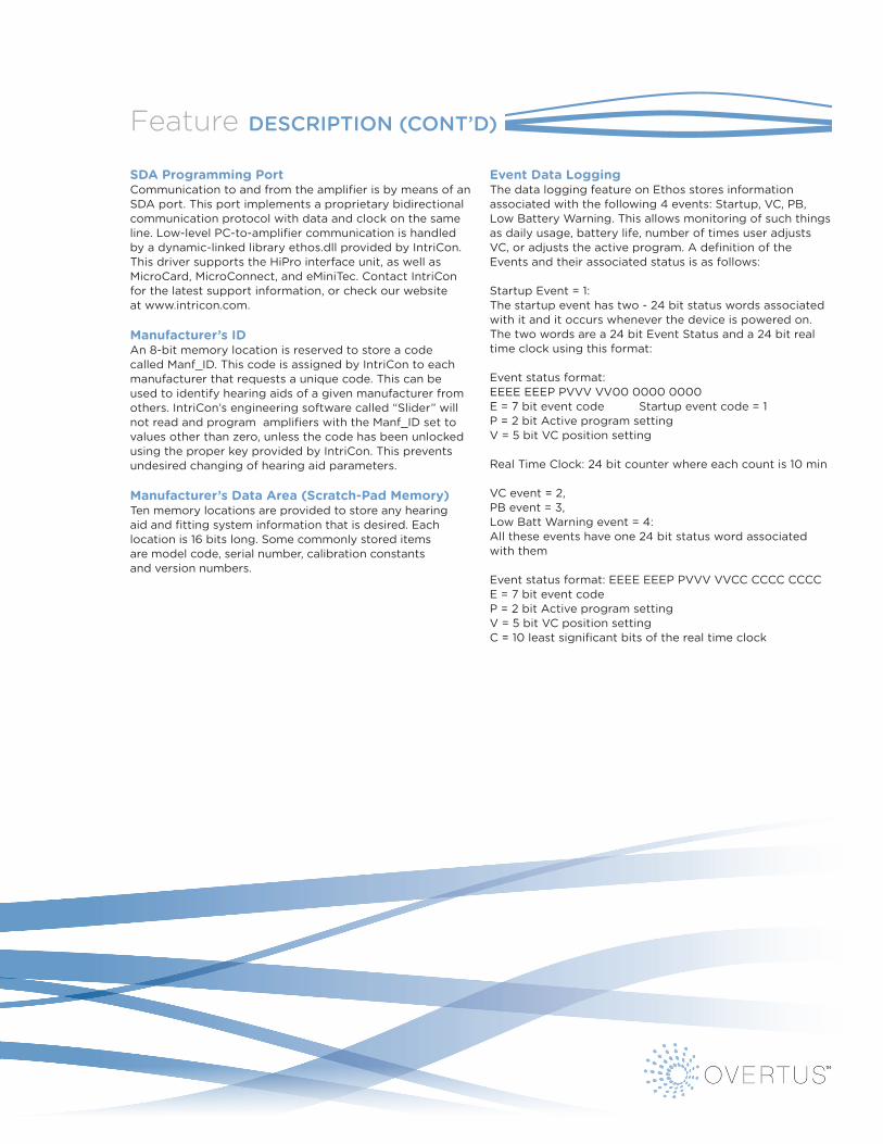
SDA Programming Port Communication to and from the amplifier is by means of an SDA port. This port implements a proprietary bidirectional communication protocol with data and clock on the same line. Low-level PC-to-amplifier communication is handled by a dynamic-linked library ethos.dll provided by IntriCon. This driver supports the HiPro interface unit, as well as MicroCard, MicroConnect, and eMiniTec. Contact IntriCon for the latest support information, or check our website at www.intricon.com.
manufacturer’s iD An 8-bit memory location is reserved to store a code called Manf_ID. This code is assigned by IntriCon to each manufacturer that requests a unique code. This can be used to identify hearing aids of a given manufacturer from others. IntriCon’s engineering software called “Slider” will not read and program amplifiers with the Manf_ID set to values other than zero, unless the code has been unlocked using the proper key provided by IntriCon. This prevents undesired changing of hearing aid parameters.
manufacturer’s Data Area (Scratch-Pad memory) Ten memory locations are provided to store any hearing aid and fitting system information that is desired. Each location is 16 bits long. Some commonly stored items are model code, serial number, calibration constants and version numbers.
event Data logging The data logging feature on Ethos stores information associated with the following 4 events: Startup, VC, PB, Low Battery Warning. This allows monitoring of such things as daily usage, battery life, number of times user adjusts VC, or adjusts the active program. A definition of the Events and their associated status is as follows:
Startup Event = 1: The startup event has two - 24 bit status words associated with it and it occurs whenever the device is powered on. The two words are a 24 bit Event Status and a 24 bit real time clock using this format:
Event status format: EEEE EEEP PVVV VV00 0000 0000 E = 7 bit event code Startup event code = 1 P = 2 bit Active program setting V = 5 bit VC position setting
Real Time Clock: 24 bit counter where each count is 10 min
VC event = 2, PB event = 3, Low Batt Warning event = 4: All these events have one 24 bit status word associated with them
Event status format: EEEE EEEP PVVV VVCC CCCC CCCC E = 7 bit event code P = 2 bit Active program setting V = 5 bit VC position setting C = 10 least significant bits of the real time clock

PCB Hybrid Package information
overtus™ Standard Hybrid PackagePart number 92333-0009
overtus™ mini Hybrid PackagePart number 92232-0009
pad detailhybrid mechsreflow info
OB
GN
D
SW VC2
TSW
VC TC+
TC-
DAI
OA
VBAT
SDA
nc nc M-
M+
MIC
1
MIC
2
RBAT CLK DAT
0.13
4"[3
.40m
m]
0.226" [5.74mm] 0.065"[1.65mm]
typical pad size:0.017 x 0.043"
[0.43 x 1.09mm]
typical spacebetween pads:
0.007" [0.18mm]
nc = no connection
33309WWYY
AbbreviatedPart Number
Date Code:WW = week numberYY = year
part number 92333-0009 - RoHS compliant
PCB Hybrid Package Information
pad detailhybrid mechsreflow info
OB
0.11
5"[2
.92m
m]
0.206" [5.23mm]0.060"
[1.52mm]
typical pad size:0.021 x 0.028"[0.53 x .71mm]
typical spacebetween pads:
0.007" [0.18mm]
23209WWYY
inches [millimeters]
AbbreviatedPart Number
Date Code:WW = week numberYY = year
OAGNDSDAM+
M-
MIC1
MIC2 SW TSW VC2 VCVBAT
CLKDAT
2V
part number 92232-0009 - RoHS compliant
pad detailhybrid mechsreflow info
OB
GN
D
SW VC2
TSW
VC TC+
TC-
DAI
OA
VBAT
SDA
nc nc M-
M+
MIC
1
MIC
2
RBAT CLK DAT
0.13
4"[3
.40m
m]
0.226" [5.74mm] 0.065"[1.65mm]
typical pad size:0.017 x 0.043"
[0.43 x 1.09mm]
typical spacebetween pads:
0.007" [0.18mm]
nc = no connection
33309WWYY
AbbreviatedPart Number
Date Code:WW = week numberYY = year
part number 92333-0009 - RoHS compliant
PCB Hybrid Package Information
pad detailhybrid mechsreflow info
OB
0.11
5"[2
.92m
m]
0.206" [5.23mm]0.060"
[1.52mm]
typical pad size:0.021 x 0.028"[0.53 x .71mm]
typical spacebetween pads:
0.007" [0.18mm]
23209WWYY
inches [millimeters]
AbbreviatedPart Number
Date Code:WW = week numberYY = year
OAGNDSDAM+
M-
MIC1
MIC2 SW TSW VC2 VCVBAT
CLKDAT
2V
part number 92232-0009 - RoHS compliant
VC2
Applications
M-
M+
MIC1
DAI
TC-
TC+
VBAT
SDA
GND
OA
OB
to p
rogr
amm
er
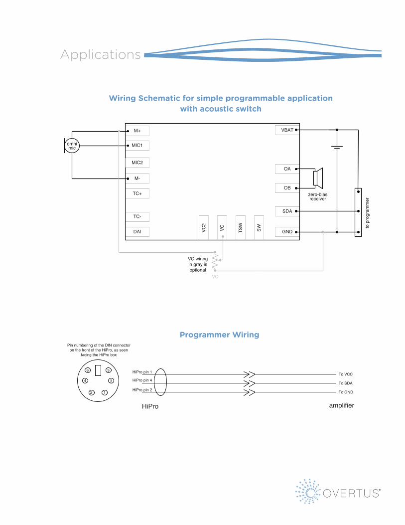
Wiring Schematic for simple programmable applicationwith acoustic switch
VC TSW
SW
omnimic
MIC2
zero-biasreceiver
VC wiring in gray is optional
VC
HiPro pin 1
HiPro pin 2
HiPro pin 4To VCC
To GND
To SDA
1
3
5
2
4
6
Pin numbering of the DIN connector on the front of the HiPro, as seen
facing the HiPro box
amplifierHiPro
Programmer Wiring
Applications
Wiring Schematic for simple programmable application with acoustic switch
VC2
Applications
M-
M+
MIC1
DAI
TC-
TC+
VBAT
SDA
GND
OA
OB
to p
rogr
amm
er
Wiring Schematic for simple programmable applicationwith acoustic switch
VC TSW
SW
omnimic
MIC2
zero-biasreceiver
VC wiring in gray is optional
VC
HiPro pin 1
HiPro pin 2
HiPro pin 4To VCC
To GND
To SDA
1
3
5
2
4
6
Pin numbering of the DIN connector on the front of the HiPro, as seen
facing the HiPro box
amplifierHiPro
Programmer WiringProgrammer Wiring
IntriCon Hybrid part
number
Customer Attach
process Process Parameters
Max Hybrid Temp
Recommended materials to attach hybrid
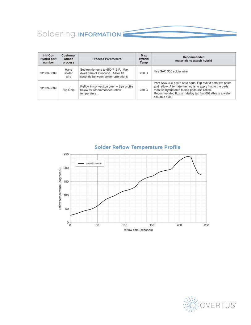
92333-0009 Hand solder wire
Set iron tip temp to 650-715 F. Max dwell time of 2 second. Allow 10 seconds between solder operations
250 C Use SAC 305 solder wire
92333-0009 Flip Chip Reflow in convection oven – See profile below for recommended reflow temperature.
250 C
Print SAC 305 paste onto pads. Flip hybrid onto wet paste and reflow. Alternate method is to apply flux to the pads then flip hybrid onto fluxed pads and reflow. Recommended flux is Indalloy tac flux 009 (this is a water soluable flux.)
0
50
100
150
200
250
reflo
w te
mpe
ratu
re (d
egre
es C
)
500 100 150 200 250reflow time (seconds)
pn 91839-0009
Soldering Information
Solder Reflow Temperature Profile
92333-0009
Solder reflow Temperature Profile
IntriCon Hybrid part
number
Customer Attach
process Process Parameters
Max Hybrid Temp
Recommended materials to attach hybrid
92333-0009 Hand solder wire
Set iron tip temp to 650-715 F. Max dwell time of 2 second. Allow 10 seconds between solder operations
250 C Use SAC 305 solder wire
92333-0009 Flip Chip Reflow in convection oven – See profile below for recommended reflow temperature.
250 C
Print SAC 305 paste onto pads. Flip hybrid onto wet paste and reflow. Alternate method is to apply flux to the pads then flip hybrid onto fluxed pads and reflow. Recommended flux is Indalloy tac flux 009 (this is a water soluable flux.)
0
50
100
150
200
250
reflo
w te
mpe
ratu
re (d
egre
es C
)
500 100 150 200 250reflow time (seconds)
pn 91839-0009
Soldering Information
Solder Reflow Temperature Profile
92333-0009
Soldering information