high-level views in object-oriented systems using formal...
TRANSCRIPT

High-Level Viewsin Object-Oriented Systems
using Formal Concept Analysis
Inauguraldissertationder Philosophisch-naturwissenschaftlichen Fakultat
der Universitat Bern
vorgelegt von
Gabriela Beatriz Ar evalo
von Argentinien
Leiter der Arbeit:Prof. Dr. Stephane DucasseProf. Dr. Oscar Nierstrasz
Institut fur Informatik und angewandte Mathematik
Von der Philosophisch-naturwissenschaftlichen Fakultat angenommen.
Bern, 14.12.2004 Der Dekan:
Prof. Paul Messerli


This work is dedicatedto Mom and Dad


Abstract
Within object-oriented systems there are different meaningful dependencies between different objects.These dependencies revealcontracts, collaborationsand relationshipsbetween classes, methods, pack-ages and any development unit in the systems. In most of the cases, these dependencies are not explicitin the code. This problem is due to inadequate or out-of-date documentation and mechanisms such asdynamic binding, inheritance and polymorphism that obscure the presence of existing dependencies.
These dependencies play an important part in implicit contracts between the various software artifacts ofthe system. It is therefore essential that a developer, who has to make changes or extensions to an object-oriented system, understands the dependencies among the classes. Lack of understanding increases the riskthat seemingly innocuous changes break the implicit existing contracts in the system. In short, implicit,undocumented dependencies lead tofragile systemsthat are difficult to extend or modify correctly.
In this thesis we develop an approach – based on a methodology and a tool support – to recover thisimplicit information and generatehigh-level views of a system at different abstraction levels, using aformal clustering technique called Formal Concept Analysis (FCA). With theseviews, we help to build thefirst mental model of a system. Thus the implicit or lost information is made explicit and we are able to finduses of coding styles, possible bottlenecks and weakpoints of a system, identify eventual contracts betweenthe entities,patternsbased on the dependencies and – if possible – propose possible solutions to correctproblems in the code. With this approach we also evaluate which are the advantages and disadvantages ofusing a clustering technique in software reverse engineering.


Acknowledgements
This adventure started in October 2000 when I arrived in Bern to work in the Software Composition Group.And the 4 years I have spent since this date, I must confess has been an interesting experience.
After all these four years, I have got a list of people who contributed in different ways to my Ph.D. thesis,for which I would like to express thanks.
I thank Prof. Oscar Nierstrasz. He believed in my ability to do the Ph.D. thesis in the Software CompositionGroup, he gave me guidance and support throughout these four years, and he offered me useful professionaladvice.
I thank Prof. Stephane Ducasse. He is the “motivation machine” of the Software Composition Group anda friend that I met in SCG. He helped me from the beginning of the thesis with his useful discussions,guidance and encouragement in the university and all the trips (to conferences) we have made together.From the personal viewpoint, I thank him and all his family: Florence, Quentin and Thibaut that were likemy family, especially in the first years of my stay in Switzerland. I enjoyed every moment I spent withthem.
I thank Prof. Marianne Huchard and Prof. Giuliano Antoniol. They accepted to be my external reviewersof this thesis, and offered useful comments on my thesis. They also accepted to come to my PhD defensein spite of their busy agendas, and I appreciate that a lot.
I thank Prof. Horst Bunke. for accepting to chair my Ph.D. defense.
I thank Tamar Richner, Juan Carlos Cruz and Sander Tichelaar. Their friendship and their friendly advicehave been very important and have encouraged me a lot during these 4 years.
I thank Michele Lanza and Orla Greevy. They were my office colleagues and shared with me the room 106every day of these 4 years. I appreciate them a lot because they were the proof-readers of the first drafts ofmy thesis with Tudor Gırba. We laughed a lot, we had crazy discussions and supported ourselves in goodand bad moments.
I thank Franch Buchli. He was my master student and helped me to improve my methodology and my tool.I appreciate all the work and effort he made forConAn.
I thank all the rest of people in the SCG: Franz Achermann, Alexandre Bergel, Calogero Butera, MarkusDenker, Markus Gaelli, Tudor Gırba, Nathanael Schaerli, Laura Ponisio, Daniele Talerico, David Vogel,Roel Wuyts. We shared nice barbecues, tea-times, coffee-times and interesting discussions in the Univer-sity.
I thank Therese Schmid. She was my main support in all the administrative papers in the University, butalso one of my providers of chocolates and cookies in the SCG.
I thank all people I met in the conferences. I have had nice moments with them and also useful discussionsto help me to improve my work.
I thank all people I met in “Cruz del Sur” and Mision Catolica in Bern. They represent my “other life”during my stay in Switzerland, especially during weekends
I thank my friends Ana Maria Hintermann, Silvana Nicolini, Marcelo and Silvia Morard, Trudi Crego andAlejandro Strickler, Karina Mayocchi and Alejandro Juroczko. We spent crazy moments together and were

the supporters of this thesis too.
I thank my brothers and sisters Dario, Cynthia, Patricia and Cristian. Myfor everfan club and the support-ers that any team in the world would like to have.
I thank Jorge, who encouraged me during last year with his love and his advice.
I thank Papa and Mama. They supported me with all their strengths and love in this project, although I wasso far from home. If God gave me the opportunity to choose another parents, I would choose them again.I love them !
Thank you everybody from the depth of my heart !!

Contents
1 Introduction 1
1.1 The Problem . . . . . . . . . . . . . . . . . . . . . . . . . . . . . . . . . . . . . . . . . . 2
1.2 Our Approach . . . . . . . . . . . . . . . . . . . . . . . . . . . . . . . . . . . . . . . . . 3
1.3 Contributions . . . . . . . . . . . . . . . . . . . . . . . . . . . . . . . . . . . . . . . . . 4
1.4 Thesis Outline . . . . . . . . . . . . . . . . . . . . . . . . . . . . . . . . . . . . . . . . . 6
2 Dependencies in Object-Oriented Systems 7
2.1 Introduction . . . . . . . . . . . . . . . . . . . . . . . . . . . . . . . . . . . . . . . . . . 7
2.2 Problems in Object-Oriented Systems . . . . . . . . . . . . . . . . . . . . . . . . . . . . 8
2.2.1 Terminology . . . . . . . . . . . . . . . . . . . . . . . . . . . . . . . . . . . . . 8
2.2.2 Common Problems in Object-Oriented Code . . . . . . . . . . . . . . . . . . . . 8
2.3 Goals of our Approach . . . . . . . . . . . . . . . . . . . . . . . . . . . . . . . . . . . . 10
2.4 Reverse Engineering: State of the Art . . . . . . . . . . . . . . . . . . . . . . . . . . . . 11
2.5 Software Clustering . . . . . . . . . . . . . . . . . . . . . . . . . . . . . . . . . . . . . . 12
2.5.1 Common Problems for Clustering Techniques . . . . . . . . . . . . . . . . . . . . 12
2.5.2 Requirements for Clustering Techniques . . . . . . . . . . . . . . . . . . . . . . . 12
2.5.3 State of the Art . . . . . . . . . . . . . . . . . . . . . . . . . . . . . . . . . . . . 13
2.6 Conclusions . . . . . . . . . . . . . . . . . . . . . . . . . . . . . . . . . . . . . . . . . . 15
3 Formal Concept Analysis in High-Level Views 17
3.1 Introduction . . . . . . . . . . . . . . . . . . . . . . . . . . . . . . . . . . . . . . . . . . 17
3.2 Overview of the Approach . . . . . . . . . . . . . . . . . . . . . . . . . . . . . . . . . . 17
3.3 FCA Applied in Software Engineering . . . . . . . . . . . . . . . . . . . . . . . . . . . . 19
3.4 Our Approach in Depth . . . . . . . . . . . . . . . . . . . . . . . . . . . . . . . . . . . . 20
3.5 Conclusions . . . . . . . . . . . . . . . . . . . . . . . . . . . . . . . . . . . . . . . . . . 23
3.5.1 Research Questions . . . . . . . . . . . . . . . . . . . . . . . . . . . . . . . . . . 23
3.5.2 Summary . . . . . . . . . . . . . . . . . . . . . . . . . . . . . . . . . . . . . . . 24
4 XRay Views 25
4.1 Problems in Understanding Classes . . . . . . . . . . . . . . . . . . . . . . . . . . . . . . 25
4.2 Goals ofXRay Views . . . . . . . . . . . . . . . . . . . . . . . . . . . . . . . . . . . . . 26
vii

CONTENTS
4.3 Formal Concept Analysis in Class Understanding . . . . . . . . . . . . . . . . . . . . . . 26
4.3.1 Elements and Properties of Classes . . . . . . . . . . . . . . . . . . . . . . . . . 27
4.3.2 Properties among Groups . . . . . . . . . . . . . . . . . . . . . . . . . . . . . . . 28
4.3.3 Interpretation . . . . . . . . . . . . . . . . . . . . . . . . . . . . . . . . . . . . . 28
4.4 XRay Views . . . . . . . . . . . . . . . . . . . . . . . . . . . . . . . . . . . . . . . . . . 30
4.4.1 XRay View: STATE USAGE . . . . . . . . . . . . . . . . . . . . . . . . . . . . . 31
4.4.2 XRay View: EXTERNAL /INTERNAL CALLS . . . . . . . . . . . . . . . . . . . . 33
4.4.3 XRay View: BEHAVIOURAL SKELETON . . . . . . . . . . . . . . . . . . . . . . 34
4.5 Application of the Approach: Analysis . . . . . . . . . . . . . . . . . . . . . . . . . . . . 35
4.6 Discussion . . . . . . . . . . . . . . . . . . . . . . . . . . . . . . . . . . . . . . . . . . . 36
4.7 Related Work . . . . . . . . . . . . . . . . . . . . . . . . . . . . . . . . . . . . . . . . . 37
4.8 Conclusions . . . . . . . . . . . . . . . . . . . . . . . . . . . . . . . . . . . . . . . . . . 37
4.8.1 Summary . . . . . . . . . . . . . . . . . . . . . . . . . . . . . . . . . . . . . . . 37
4.8.2 Research Questions . . . . . . . . . . . . . . . . . . . . . . . . . . . . . . . . . . 38
4.8.3 Future Work . . . . . . . . . . . . . . . . . . . . . . . . . . . . . . . . . . . . . 38
5 Hierarchy Schemas 39
5.1 Problems in Understanding Class Hierarchies . . . . . . . . . . . . . . . . . . . . . . . . 39
5.2 Goals of Hierarchy Schemas . . . . . . . . . . . . . . . . . . . . . . . . . . . . . . . . . 40
5.3 Formal Concept Analysis in Analyzing Class Hierarchies . . . . . . . . . . . . . . . . . . 40
5.3.1 Elements and Properties of Classes . . . . . . . . . . . . . . . . . . . . . . . . . 40
5.3.2 Interpretation of the Properties in Concepts . . . . . . . . . . . . . . . . . . . . . 41
5.4 Detected Dependency Schemas . . . . . . . . . . . . . . . . . . . . . . . . . . . . . . . . 42
5.4.1 Global View onCollection Hierarchy . . . . . . . . . . . . . . . . . . . . . . . . . 42
5.4.2 “Class-Based” View onSortedCollection . . . . . . . . . . . . . . . . . . . . . . 44
5.5 Application of the Approach: Analysis . . . . . . . . . . . . . . . . . . . . . . . . . . . . 48
5.6 Discussion . . . . . . . . . . . . . . . . . . . . . . . . . . . . . . . . . . . . . . . . . . . 49
5.7 Related Work . . . . . . . . . . . . . . . . . . . . . . . . . . . . . . . . . . . . . . . . . 50
5.8 Conclusions . . . . . . . . . . . . . . . . . . . . . . . . . . . . . . . . . . . . . . . . . . 50
5.8.1 Summary . . . . . . . . . . . . . . . . . . . . . . . . . . . . . . . . . . . . . . . 50
5.8.2 Research Questions . . . . . . . . . . . . . . . . . . . . . . . . . . . . . . . . . . 51
5.8.3 Future Work . . . . . . . . . . . . . . . . . . . . . . . . . . . . . . . . . . . . . 51
6 Collaboration Patterns 53
6.1 Goals of Collaboration Patterns . . . . . . . . . . . . . . . . . . . . . . . . . . . . . . . . 53
6.2 Formal Concept Analysis in Analyzing an Application . . . . . . . . . . . . . . . . . . . 54
6.2.1 FCA Mapping: Setup of the Formal Context . . . . . . . . . . . . . . . . . . . . 54
6.2.2 ConAn Engine: Calculation of the Concepts . . . . . . . . . . . . . . . . . . . . . 56
6.2.3 Concept Lattice: Post Filtering . . . . . . . . . . . . . . . . . . . . . . . . . . . . 56
6.2.4 Pattern Neighborhood . . . . . . . . . . . . . . . . . . . . . . . . . . . . . . . . 58
viii

CONTENTS
6.3 Validation: Case Studies . . . . . . . . . . . . . . . . . . . . . . . . . . . . . . . . . . . 61
6.4 Application of the Approach: Analysis . . . . . . . . . . . . . . . . . . . . . . . . . . . . 62
6.5 Discussion . . . . . . . . . . . . . . . . . . . . . . . . . . . . . . . . . . . . . . . . . . . 65
6.6 Related Work . . . . . . . . . . . . . . . . . . . . . . . . . . . . . . . . . . . . . . . . . 66
6.7 Conclusions . . . . . . . . . . . . . . . . . . . . . . . . . . . . . . . . . . . . . . . . . . 67
6.7.1 Summary . . . . . . . . . . . . . . . . . . . . . . . . . . . . . . . . . . . . . . . 67
6.7.2 Research Questions . . . . . . . . . . . . . . . . . . . . . . . . . . . . . . . . . . 68
6.7.3 Future Work . . . . . . . . . . . . . . . . . . . . . . . . . . . . . . . . . . . . . 68
7 Conclusions 71
7.1 Summary . . . . . . . . . . . . . . . . . . . . . . . . . . . . . . . . . . . . . . . . . . . 71
7.2 Research Questions . . . . . . . . . . . . . . . . . . . . . . . . . . . . . . . . . . . . . . 71
7.3 Lessons Learned . . . . . . . . . . . . . . . . . . . . . . . . . . . . . . . . . . . . . . . 73
7.4 Future Work . . . . . . . . . . . . . . . . . . . . . . . . . . . . . . . . . . . . . . . . . . 74
A ConAn Framework 75
A.1 Introduction . . . . . . . . . . . . . . . . . . . . . . . . . . . . . . . . . . . . . . . . . . 75
A.2 The Meta-Model: Moose . . . . . . . . . . . . . . . . . . . . . . . . . . . . . . . . . . . 75
A.3 ConAn: a Framework for FCA . . . . . . . . . . . . . . . . . . . . . . . . . . . . . . . . 76
A.3.1 Features ofConAn . . . . . . . . . . . . . . . . . . . . . . . . . . . . . . . . . . 76
A.3.2 Components ofConAn . . . . . . . . . . . . . . . . . . . . . . . . . . . . . . . . 76
A.4 Fish Eye View . . . . . . . . . . . . . . . . . . . . . . . . . . . . . . . . . . . . . . . . . 78
A.5 User Interface . . . . . . . . . . . . . . . . . . . . . . . . . . . . . . . . . . . . . . . . . 79
A.5.1 User Interface ofXRay Views . . . . . . . . . . . . . . . . . . . . . . . . . . . . 79
A.5.2 User Interface of Hierarchy Schemas . . . . . . . . . . . . . . . . . . . . . . . . 81
A.5.3 User Interface of Collaboration Patterns . . . . . . . . . . . . . . . . . . . . . . . 83
B Introduction to Formal Concept Analysis 87
B.1 Introduction . . . . . . . . . . . . . . . . . . . . . . . . . . . . . . . . . . . . . . . . . . 87
B.2 Context and Concepts . . . . . . . . . . . . . . . . . . . . . . . . . . . . . . . . . . . . . 88
B.3 Concept Lattice . . . . . . . . . . . . . . . . . . . . . . . . . . . . . . . . . . . . . . . . 89
B.4 Concepts Labels in the Concept Lattice . . . . . . . . . . . . . . . . . . . . . . . . . . . 91
B.5 Concepts Builder Algorithms . . . . . . . . . . . . . . . . . . . . . . . . . . . . . . . . . 91
B.5.1 Bottom-up Algorithm . . . . . . . . . . . . . . . . . . . . . . . . . . . . . . . . 91
B.5.2 Ganter Algorithm . . . . . . . . . . . . . . . . . . . . . . . . . . . . . . . . . . . 93
B.6 Lattice Builder Algorithm . . . . . . . . . . . . . . . . . . . . . . . . . . . . . . . . . . . 94
B.7 Concept Partitions . . . . . . . . . . . . . . . . . . . . . . . . . . . . . . . . . . . . . . . 94
B.8 Finding Partitions in a Concept Lattice . . . . . . . . . . . . . . . . . . . . . . . . . . . . 98
ix


List of Figures
1.1 XRay views applied on a class . . . . . . . . . . . . . . . . . . . . . . . . . . . . . . . . 4
1.2 Hierarchy Schemas on a Class Hierarchy . . . . . . . . . . . . . . . . . . . . . . . . . . 5
1.3 Collaboration Pattern identified in the application . . . . . . . . . . . . . . . . . . . . . . 5
3.1 The overall approach . . . . . . . . . . . . . . . . . . . . . . . . . . . . . . . . . . . . . 18
4.1 Attribute accesses and method invocations and the identified groups. . . . . . . . . . . . . 27
4.2 GroupCollaborating Attributesof theXRay view STATE USAGE in OrderedCollection . . 31
5.1 Ancestor Direct State Access. . . . . . . . . . . . . . . . . . . . . . . . . . . . . . . . . 44
5.2 Cancelled Inherited Behavior. . . . . . . . . . . . . . . . . . . . . . . . . . . . . . . . . 44
5.3 Inherited and Local Invocations - Case 1 . . . . . . . . . . . . . . . . . . . . . . . . . . . 45
5.4 Inherited and Local Invocations - Case 2 . . . . . . . . . . . . . . . . . . . . . . . . . . . 45
5.5 Reuse of Superclass Behavior. . . . . . . . . . . . . . . . . . . . . . . . . . . . . . . . . 45
5.6 Dependency Schemas inSortedCollection . . . . . . . . . . . . . . . . . . . . . . . . . . 46
5.7 Cancelled Local Behavior and Behavior Reuse of Superclasses . . . . . . . . . . . . . . . 47
5.8 Brokensupersend Chain . . . . . . . . . . . . . . . . . . . . . . . . . . . . . . . . . . . 47
5.9 Inherited and Local Invocations. . . . . . . . . . . . . . . . . . . . . . . . . . . . . . . . 48
6.1 Example class diagram . . . . . . . . . . . . . . . . . . . . . . . . . . . . . . . . . . . . 55
6.2 Structural relationships of the Composite Pattern . . . . . . . . . . . . . . . . . . . . . . 56
6.3 The intent graph of concepts 2, 4 and 8 of Table 6.2 . . . . . . . . . . . . . . . . . . . . . 57
6.4 Adapter Pattern with two sets of classes . . . . . . . . . . . . . . . . . . . . . . . . . . . 57
6.5 Almost and overloaded patterns of a Composite Pattern . . . . . . . . . . . . . . . . . . . 59
6.6 Resulting lattice of Incidence Table 6.1 . . . . . . . . . . . . . . . . . . . . . . . . . . . . 59
6.7 Sub and cover patterns of the Composite Pattern (p2) . . . . . . . . . . . . . . . . . . . . 60
6.8 ThreeSubclass Starsof CodeCrawler . . . . . . . . . . . . . . . . . . . . . . . . . . . . 66
6.9 Unproblematic orders for calculation . . . . . . . . . . . . . . . . . . . . . . . . . . . . . 69
A.1 Moosearchitecture. . . . . . . . . . . . . . . . . . . . . . . . . . . . . . . . . . . . . . . 76
A.2 The overall approach . . . . . . . . . . . . . . . . . . . . . . . . . . . . . . . . . . . . . 77
A.3 Example class diagram . . . . . . . . . . . . . . . . . . . . . . . . . . . . . . . . . . . . 78
xi

LIST OF FIGURES
A.4 Resulting lattice of Incidence Table A.1 . . . . . . . . . . . . . . . . . . . . . . . . . . . 79
A.5 Implementation of theFish Eye Viewin ConAn . . . . . . . . . . . . . . . . . . . . . . . 80
A.6 ConAn PaDiwith the result from the classes of Figure A.3 . . . . . . . . . . . . . . . . . 80
A.7 Importer of classes inXRay Views . . . . . . . . . . . . . . . . . . . . . . . . . . . . . . 81
A.8 Visualizer ofXRay Views . . . . . . . . . . . . . . . . . . . . . . . . . . . . . . . . . . 82
A.9 Importer of Class Hierarchies in Hierarchy Schemas . . . . . . . . . . . . . . . . . . . . . 82
A.10 Visualizer of Hierarchy Schemas . . . . . . . . . . . . . . . . . . . . . . . . . . . . . . . 83
A.11 Importer of classes of Collaboration Patterns . . . . . . . . . . . . . . . . . . . . . . . . . 84
B.1 The lattice of the mammals example with classical notation. . . . . . . . . . . . . . . . . 89
B.2 The lattice of the mammals example with complete notation. . . . . . . . . . . . . . . . . 90
B.3 The lattice for the mammals example with unique properties. . . . . . . . . . . . . . . . . 95
B.4 The lattice of the complemented mammals example. . . . . . . . . . . . . . . . . . . . . 97
xii

List of Tables
4.1 Data about the classes (HNL indicates the level of inheritance) . . . . . . . . . . . . . . . 30
5.1 Commonly Identified Schemas. . . . . . . . . . . . . . . . . . . . . . . . . . . . . . . . . 43
6.1 Order 3 context for the example in Figure 6.1 . . . . . . . . . . . . . . . . . . . . . . . . 55
6.2 Concepts of the example in Figure 6.1 . . . . . . . . . . . . . . . . . . . . . . . . . . . . 56
6.3 Concepts of the example in Figure 6.4 . . . . . . . . . . . . . . . . . . . . . . . . . . . . 57
6.4 Resulting Patterns after the merging of equivalent patterns from the concepts of Table 6.2 . 58
6.5 Final Patterns after applying the post filters to the concepts from Table 6.2 . . . . . . . . . 60
6.6 Statistical overview of the cases . . . . . . . . . . . . . . . . . . . . . . . . . . . . . . . 61
6.7 Used Classifiers . . . . . . . . . . . . . . . . . . . . . . . . . . . . . . . . . . . . . . . . 61
6.8 Classifier statistics . . . . . . . . . . . . . . . . . . . . . . . . . . . . . . . . . . . . . . 62
6.9 Patterns of higher order of a set of core classes from CodeCrawler . . . . . . . . . . . . . 62
6.10 Structure of investigated patterns . . . . . . . . . . . . . . . . . . . . . . . . . . . . . . . 63
6.11 Investigated Patterns . . . . . . . . . . . . . . . . . . . . . . . . . . . . . . . . . . . . . 64
6.12 Comparison between our inductive approach and the inductive approach from Tonella . . . 67
A.1 Order 3 context for the example in Figure A.3 . . . . . . . . . . . . . . . . . . . . . . . . 79
B.1 Mammal example: TableT represents the binary relations . . . . . . . . . . . . . . . . . 87
B.2 Concepts of the mammal example . . . . . . . . . . . . . . . . . . . . . . . . . . . . . . 89
B.3 Calculation of the extents of the mammal example using Ganter algorithm . . . . . . . . . 94
B.4 The extension with unique properties of mammal context . . . . . . . . . . . . . . . . . . 95
B.5 Concepts of the mammal example . . . . . . . . . . . . . . . . . . . . . . . . . . . . . . 96
B.6 Concept partitions of the mammal concept extended with unique properties . . . . . . . . 96
B.7 The extension with complemented extension mammal context . . . . . . . . . . . . . . . 97
B.8 Concepts of the mammal example . . . . . . . . . . . . . . . . . . . . . . . . . . . . . . 97
B.9 Concept partitions of the mammal concept extended with complemented properties . . . . 98
xiii


List of Algorithms
B.1 Algorithm to build the lattice. . . . . . . . . . . . . . . . . . . . . . . . . . . . . . . . . . 94B.2 Algorithm to calculate the complemented extension of a context . . . . . . . . . . . . . . 96B.3 Algorithm to find the partitions of a well-formed concept lattice. . . . . . . . . . . . . . . 98
xv


Chapter 1
Introduction
Today large organizations are not only faced with the problem of replacing their information systemswith completely new ones, but they have to maintain or gain control over their legacy systems [DDN02].During the maintenance phase of the software lifecycle, developers must constantly cope with evolvingrequirements, such as new platforms, new technologies, new users’ needs or new functionalities. Thesechanges are inevitable in the software lifecycle [Par94].
When the developer must face with these changes, the first step is reverse engineering the system. Ac-cording to Chikofsky’s definition [CC92]“reverse engineering is the process of analyzing a subject systemto (1) identify the system’s components and their interrelationships and (2) create representations of thesystem in another form or at a higher level of abstraction”.The main goal in this step of a reengineeringprocess of a software is to generate a mental model of the system [SFM99]. This mental model must bethe first step in analyzing a software. In any software this mental model is the first fingerprints of the sys-tem identifying components and relationships between them at different abstraction levels. Specifically, inobject-oriented systems, the components can be methods, variables, classes, or a set of classes, the interre-lationships can be inheritance, methods calls, etc, and the abstraction levels identified then are class-, classhierarchy- or application-levels.
Unfortunately building this mental model is not a trivial task because not all the relationships are explicitat the source code level. Besides that if we want to detect them using any kind of documentation – suchas manuals about design in case of industrial projects or simple code comments –, most of the cases it isout-of-date or insufficient. These relationships are important because they reveal meaningful dependenciesbetween different components of the system. When this knowledge is not explicit or is lost, any change inthe system is complex and can break the current functionalities or introduce new unexpected relationshipsincreasing the complexity of the system to be understood.
Summarizing from these issues, we state that the main problem is:
Without precise and updated documentation, a system is like apuzzle, where the pieceshave no order at all. Thus, the software engineer is not able to infer what is implemented,what are the imposed constraints and how the system is working. The software engineerneeds an approach to cope with this problem to be able to analyze a system.
In this thesis we develop an approach where we recover thisimplicit information and generatehigh-levelviews of a system using a formal clustering technique called Formal Concept Analysis (FCA) [GW99].With theseviews, we help to build the first mental model of a system. Thus the implicit or lost informationis made explicit and we are able to find uses of coding styles, possible bottlenecks and weakpoints of asystem, identify eventual contracts [SLMD96] between the entities,patternsbased on the dependenciesand – if possible – propose possible solutions to correct problems in the code.
1

Introduction Chapter 1
1.1 The Problem
In Introduction we state that the main problem in building a mental model is that the system has hiddeninformation that must be explicit to understand how the system is working.
To cope with this problem, this thesis is focused on two research directions based on the following ques-tions:
• How we can identify and detect implicit dependencies between the objects in a system?
• What is the adequate tool support to provide an infrastructure to the dependencies detection ?
Let’s analyze in detail which are the different problems in these two research directions.
Identification of Dependencies: In object-oriented systems there are different meaningful dependenciesbetween different objects. These dependencies reveal contracts, collaborations and relationships betweenclasses, methods, packages and any development unit in the system. These dependencies are determinedby different building mechanisms of object-oriented systems:reuse, delegation, data encapsulation, dy-namic binding, inheritanceandpolymorphism. Although these mechanisms represent advantages of object-oriented systems, the maintainers of object-oriented systems must cope with several problems. The mostimportant is that not all these dependencies are explicit in the system. Some examples are following:
• Example 1:In Smalltalk, there exists theCollection class hierarchy that defines all the classesresponsible for managing any kind of collections. Let’s take only the subhierarchy whose root is theOrderedCollection class. We also consider in this subhierarchy theSequeanceableCollection classwhich is the superclass ofOrderedCollection.OrderedCollection has six subclasses defined in two inheritance levels. This class defines the methodsize that calculates the amount of elements contained in the collection, and the method is inherited(and not overriden) by six subclasses. If we modify the behavior of the methodsize , or if weremove it from the class, we are breaking the functionalities of the subclasses [MS98]. In case ofremoval, a bug appears because the methodsize in SequenceableCollection is abstract.
• Example 2:A design pattern (such as Composite Pattern [GHJV95]) is implemented in a system, andthe developer did not use the right names to identify the components. Then we add a new method thatdetermine a new collaboration between the three classes of the pattern. By adding this new methodwe are hiding the existence of the pattern in the code, and we are breaking the current functionalitiesof the pattern.
• Example 3:One of the salient features ofSmalltalk is the fully reified compilation process. The devel-oper may extendSmalltalk semantics providing new compile-time features by extending the classeshierarchies whose roots areParser, ProgramNodeBuilder, ProgramNode, CodeStream, Compiled-Method, NameScope, Compiler, CompilerErrorHandler andDecompiler [Riv96]. If the developer isnot aware of the relationships between all these class hierarchies, he can break the existing languagesemantics or create a wrong one.
The existence of these implicit dependencies is followed by undesirable characteristics such as a poorlystructured source code, missing or incomplete design specifications, non-existing or out of date documen-tation, high level of redundancy or extremely complex modules. Several examples, like ones mentionedbefore, are enough to see that discovering these dependencies is important if we want to perform anychange in the code. These dependencies have three main features:
• The dependencies are not constrained to a specific development unit. They appear at the class-, classhierarchy- or application-level of a system.Example 1is a case of dependencies introduced at theclass hierarchy-level.Examples 2and3 are cases of dependencies at the application-level
• The dependencies do not appear isolated in the system.Example 1shows us the use of inheritanceand behavior reuse between classes.
2

Section 1.2 Our Approach
• The dependencies appear as recurring situations in the system. For example, the case of hook meth-ods [WBWW90] can appear several times in a class hierarchy.
We see that when a developer must reengineer a system, these problems make the task complex to managebecause any kind of unstructured changes in the system can either break existing dependencies or duplicateinformation including existing dependencies among several objects.
Tool Support: Within the context of software tools, approaches such as Godin et. al. [GMM+95] andDekel [Dek03] cope partially with these problems using also Formal Concept Analysis. But their maindrawbacks are that they use explicit dependencies (such as inheritance or method calls), and they do notdiscover implicit dependencies. Besides that, the interpretation of the results is based on some knowledgeabout the mathematical background of FCA.
In this thesis we propose an approach composed of a methodology and a tool support todetect implicit dependencies. Using FCA as a base tool, we build three different tools to an-alyze an object-oriented system at different abstraction levels: class-level, class-hierarchylevel and application level. In each level, we providehigh-level viewsthat allow to discoverwhich are the implicit information at each level, and analyze the application.
Our research is driven by the following questions:
• Do we understand how the system is implemented? What are the constraints or limits imposed in thesystem?
• How can we detect implicit unanticipated dependencies?
• How are the mechanisms such as polymorphism and inheritance used in the system?
• How can we discover defects introduced in the systems?
• How can we discover recurring situations (patterns-like) of dependencies in the systems?
• Is the mental model generated byhigh-level viewsmeaningful enough (in terms of information) tounderstand the system?
• Which are the advantages and disadvantages of using a clustering technique such FCA as a metatool?
1.2 Our Approach: Formal Concept Analysis in Object-OrientedSystems
Formal Concept Analysis provides a formal framework for recognizing groups of elements sharing com-mon properties. Based on FCA, our approach consists of a methodology and atool to support the depen-dencies detection. In the methodology, we characterize the software relationships as FCA properties andthe software artifacts as FCA elements. The group of elements and properties (named asconcepts) revealsexisting implicit and explicit dependencies in the system. With these concepts we buildhigh-level viewsonthe code to get the first mental model of the system. Thesehigh-level viewshelp the maintainer to discoverthe internal workings of a system, possible constraints and defects introduced in the system. Thesehigh-level viewsare defined in three different abstraction levels:XRay viewsat class level,hierarchy schemasat class hierarchy level andcollaboration patternsat application level.
• XRay Views on Classes:Analyzing the state and behavior of a class, we generateXRay views toshow us which are the different dependencies between methods and variables in a class.
3

Introduction Chapter 1
• Hierarchy Schemas:Analyzing the state and behavior of all the classes in a hierarchy, we identifythe different recurrent dependencies between the classes. They help the developer to understandwhich are the common and irregular design decisions when the hierarchy was built, and eventualrefactoring cases (if any) that can be applied.
• Collaboration Patterns: Analyzing structural relationships between classes in a system, we dis-coverpossible patternsthat appear in the system. With them, we analyze how the system was builtand which were the main constraints imposed in it.
Based on a generic system, Figures 1.1, 1.2 and 1.3 show the ideas of grouping software artifacts to gen-erateXRay Viewsat class level,Hierarchy Schemasat class hierarchy level andCollaboration Patternsatapplication level.
Class A
Class B Class C
Class D
Class E
Class F Class G Class H
Class IClass J
Class JAttributes: a,b,c,dMethodsm1 { ... a, b, c ... }
m2 {.... a, b ... }
m3 { ... a, b ....}
m4 { .......... self m1, self m3 ...}
m5 { self m4, self m1, self m3....}
Collaborating Attributes
Collaborating Methods
1
View 1
SYSTEM
Figure 1.1:XRay views applied on a class
The three different high-level views are complementary. If we discover a collaboration pattern that involvessub-hierarchy, and we are interested in analyzing it, we generate the hierarchical schemas on that sub-hierarchy. Or if we discover a hierarchical schema that involves aGod class, and we are interested inanalyzing it, we generate theXRay views on the class. But this does not mean that a high-level view isincluded in another high-level view of a different abstraction level. For example, aXRay view will notappear in a hierarchy schema, and this is because the different high-level views are defined with differentinformation in each abstraction level.
The tool support consists of a tool namedConAn implemented in VisualWorks [Vis03]. It is composed of4 components: abase frameworkis the implementation of FCA basics (definition of elements, propertiesand incidence table, algorithms, and visualization and navigation capabilities of the lattice). The other 3components are implemented on top of the base framework that allows the application of FCA and analysisof a system at three different abstraction levels.
1.3 Contributions
The main contributions of this thesis comprise:
• Introduction of three different high-level views based on FCA:XRay Viewson classes,HierarchySchemason class hierarchies andCollaboration Patternson applications.
4

Section 1.3 Contributions
Class A
Class B Class C
Class D
Class E
Class F Class G Class H
Class IClass J
Class EAttributes: x, y, zMethodsm1 { ........}m2 { ....... }m3 { ....... }
Class G
Methods
m4 {self m2, self m3 }
m6 { .. self m1, self m2 }
Class H
Methods
m7 { .... }
m5 { .. self m1, self m2 }
Reuse of superclass behavior
2
View 2
SYSTEM
Figure 1.2: Hierarchy Schemas on a Class Hierarchy
Class A
Class B Class C
Class D
Class E
Class F Class G Class H
Class IClass J
Class A
Methodsoperation { ... }
Class B
Methodsoperation { .... }
Class C
Methods operation { }addChild: { }removeChild: { }getChildAt: { }Group of Classes
A, B and C Candidate of a
Composite Pattern
3
View 3
SYSTEM
Figure 1.3: Collaboration Pattern identified in the application
5

Introduction Chapter 1
• Development of a methodology to analyze object-oriented system usingFormal Concept Analysis.
• Development of a tool framework calledConAnthat allows us to define three different tools wherewe apply the methodology mentioned previously at class-, class hierarchy-, and application level.
• Analysis of the advantages and constraints of using Formal Concept Analysis in building high-levelviews to reverse engineer a system, and in building support tools to generate and analyze the high-level views.
• Interpretation of results of the high-level views without having any knowledge of mathematical back-ground of FCA.
1.4 Thesis Outline
This thesis is outlined as follows:
• Chapter 2 introduces the concept ofimplicit dependencies and we identify the different problemswe find in object-oriented code, and we explain why we need three different high-level views. Wealso show how the classical reverse engineering and clustering techniques cope with the differentproblems.
• Chapter 3 introduces in detail the approach based on Formal Concept Analysis identifying the dif-ferent issues to take into account when using this approach at three different abstraction levels. Wealso summarize how Formal Concept Analysis is used in different reverse engineering problems.
• Chapter 4, 5 and 6 introduce the different high-level views we have developed:XRay Viewsappliedon classes,Hierarchy Schemasapplied on class hierarchies andCollaboration Patternson applica-tions. In the three cases, we explain in detail how FCA is applied in classes, class hierarchies andapplication respectively. Then we explain how the high-level views are generated based on the resultsprovided by FCA, and how we interpret the information we have in the high-level views. All casesare validated with case studies and we also show those results. Finally, we analyze how the issuesof the methodology –mentioned in general in the Chapter 3– affect the generation of the high-levelviews.
• Chapter 7 presents the lessons learned developing a FCA-based approach, conclusions and futurework.
• Appendix A presents details about the tool framework namedConAn
• Appendix B is a complement to the thesis and explains in detail the mathematical background andalgorithms of Formal Concept Analysis.
6

Chapter 2
Dependencies in Object-OrientedSystems
This thesis is about the application of a conceptual clustering technique called Formal Concept Analysis togeneratehigh-level viewsto detect implicit contracts determined by different dependencies between objectsin object-oriented systems. In this chapter, we explain the main context of our approach and which are thedifferent problems that object-oriented systems present. We also show how existing reverse engineeringand clustering approaches cope with these problems.
2.1 Introduction
All software systems1 are exposed to changes during their lifecycle [Par94]. Any change in the systemsimplies an evolution at large or small scale. Manny Lehman and Les Belady [LB85] have identified twomain laws of software evolution:
• Law of continuing change:A program that is used in a real-world environmentmustchange, orbecome progressively less useful in that environment.
• Law of increasing complexity:As a program evolves, it becomes morecomplex, and extra resourcesare needed to preserve and simplify its structure.
From these two laws we conclude that the changes are inevitable [Par94] and are not free, the maintainerhas to pay a price in terms ofcomplexity.
When a system must be changed, it must follow areengineeringprocess. According to Chikofsky et. al.[CC92],
Reengineeringis the examination and the alteration of a subject system to reconstitute it in anew form and the subsequent implementation of a new form.
As stated by the definition,Reengineeringconsists of two main activities, namely theexaminationand thealterationof a subject system. More formal terms for these activities areReverse EngineeringandForwardEngineering. Chikofsky et. al. [CC92] define these terms as follows,
Reverse Engineeringis the process of analysing a subject system to (i) identify the system’scomponents and their relationships and (ii) create representations of the system in anotherform or at a higher level of abstraction.
1When we use the termsystemswe refer to industrial projects and development tools implemented in any language.
7

Dependencies in Object-Oriented Systems Chapter 2
Forward Engineeringis the traditional process of moving from high-level abstractions andlogical, implementation-independent designs to the physical implementation of a system.
This thesis is within the context of the reverse engineering of object-oriented systems. Our goal is togeneratehigh-level viewson object-oriented systems at different abstraction levels. We state that,
A developer making changes or extensions to an object-oriented system must thereforeunderstand the relationships among the classes or risk that seemingly innocuous changesbreak the implicit dependencies they play a part in.
In short, any unstructured change leads tofragile systems[MS98] that are difficult to extend or modifycorrectly.
2.2 Problems in Object-Oriented Systems
The goal of our approach is to identify and understand different dependencies among classes with the staticanalysis of object-oriented code. This is not a trivial task because in most of the cases either documentationis outdated or insufficient or the code presents implicit information or the code is implemented using badstyles of code programming. Before diving into these different problems that we find in the source code,we need to define the main terms used in our approach. It is important to remark that these definitions areconstrained to the context of our work.
2.2.1 Terminology
The main terms we define aredependencyandexplicit andimplicit dependency.
Dependency. An object A depends upon another object B, if it is possible that a change to B implies thatA is affected or also needs to be changed,i.e., dependency between a client and a server.
Explicit Dependency. A dependencybetween two or more objects isexplicit when it is precisely andclearly expressed without ambiguity in the source code,i.e., definition of a direct subclass (in Smalltalk weuse the keywordsuperclass or in Java we use the keywordextends ).
Implicit Dependency. A dependencybetween two or more objects isimplicit when it can be impliedfrom the source code though is not directly expressed,i.e., chain of superclasses of a new defined class.
2.2.2 Common Problems in Object-Oriented Code
When reverse-engineering an object-oriented system, the first step a developer must perform is to get amental model of the source code [SFM99]. With this first contact, he should be able to understand whichare the different objects and different collaborations and relationships that determine the dependenciesbetween them. The dependencies play a part in implicit contracts imposed in the system [SLMD96]. Thusany change in the source code should not break any of these contracts or add new unexpected ones.
Unfortunately building this mental model is not a trivial task because in most of the cases not all the de-pendencies between the objects are explicit in the system. These meaningful dependencies are determinedby different building mechanisms, such asreuse, delegation, data encapsulation, dynamic binding, inher-itanceandpolymorphism. Let’s see briefly how these building mechanisms work and —when possible—identify some examples when they represent anexplicit or implicit dependency between objects.
8

Section 2.2 Problems in Object-Oriented Systems
• Class inheritanceis the mechanism to define a new class in terms of one or more parent classes.It means that the behavior and data associated with child classes are always an extension of theproperties associated with parent classes. A subclass has all the properties of the parent class, andothers as well.
Example:The definition of a class in terms of one or more superclasses is anexplicit dependencymeanwhile all the chain of superclasses and inherited behavior and state of a class is animplicitdependency.
• Delegationis the mechanism that lets an object delegate to another object whatever behavior the firstcan not handle.
Example: The delegation of a behavior in a method is anexplicit dependency meanwhile all thechain of delegates is aimplicit dependency.
• Dynamic binding is the mechanism to select lately the method until execution time. It has two mainaspects: determine the object (and the type), and look up in the chain of superclass for the method.
Example:The method lookup made by a chain of superclasses is animplicit dependency.
• Data encapsulation,sometimes referred to as data hiding, is the mechanism whereby the imple-mentation details of a class are kept hidden from the user. The user can only perform a restricted setof operations on the hidden members of the class by executing special functions commonly calledmethods.
• Polymorphism is used to describe a variable that may refer to objects whose class is not known atcompile time and which respond at run time according to the actual class of the object to which theyrefer. The polymorphism is shown as: (1) a variable holding a value drawn from a group of types, (2)a name associated with several different method bodies, and (3) a single method with polymorphicvariables2 as parameters
As we see each of these building mechanisms defines different kinds of dependencies. Even when thesemechanisms are used correctly, several problems can appear [WH92]:
• Although dynamic binding is one of the most flexible mechanisms in object-oriented systems, thetracing of dependencies is difficult to grasp.
• The code for any given task is usually dispersed in several methods [NR89]. When using delegation,understanding a single line of code requires tracing a chain of method invocations through severaldifferent object classes and up and down the object hierarchy.
• When using inheritance, it has been observed that it may be difficult to find, for example, the rightclass to use for a group of objects out of Smalltalk’s different classes of Collection [NR89]. Thusthe developer may have some problems in finding where different functions are carried out, either toreuse them or to modify them.
Apart from these problems, other ones are identified and are due to misuse or overuse of the differentmechanisms [Bud91]. In these cases, either unnecessary or complex dependencies are created or the de-pendencies do not exist at all.
• Classes that make direct modifications to other classes:Behavior that leads to the modification ofdata contained in another class are a violation of the encapsulation. This violation leads to unneces-sary hidden dependencies between classes.
• Classes with too much responsibility:Classes with too much responsibility need to learn to delegatesome of their responsibility to subordinate or helper Classes. Often a portion of the class behaviorcan be abstracted out and assigned to a helper class [BMMM98].
• Classes with no responsibility:A class with no responsibility serves no function, and usually can beeliminated in a manner that improves the design [FBB+99].
2A polymorphic variableis a variable declared as one class that can hold values from subclasses
9

Dependencies in Object-Oriented Systems Chapter 2
• Classes with unused responsibility:A class with responsibilities that are not used serves no functioneither.
• Misleading names:This problem can be provoked by the wrong use of polymorphism. If a systemcontains several implementation of the same message with significantly different effects, a developercan be misled in interpreting the code, and eventually introduce errors when changes are made.
• Unconnected responsibilities:This problem occurs when a class has a collection of responsibilitiesthat are not connected by data, functionality, or any other obvious binding.
• Inappropriate use of inheritance:This problem occurs when the relationships between class andsuperclass is not “is-a”, or when the class can not inherit useful behavior from the superclass.
• Repeated functionality:This problem occurs when code is duplicated in two or more classes, insteadof being abstracted into a common superclass.
From our experience in analyzing the source code [Are03, ADN03, ABN04], we have identified five mainfeatures of these problems:
1. The presence of dependencies is obscure when we have overuse or misuse of the building mecha-nisms in object-oriented systems.
2. The problems occur several times in a system,i.e., repeated functionality can appear in differentparts of software in a system.
3. The problems do not occur isolated in a system,i.e., a class can have too much responsibilities anddoes not inherit useful behavior from the superclass.
4. The problems can appear at different levels in the code,i.e., repeated functionality is a problem atthe application level, inappropriate use of inheritance is a problem at the class hierarchy level andunconnected responsibilities is a problem at the class level.
5. No tool is able to detect the recurring occurrences of these dependencies.
These features define which are the different constraints that we must solve to be able to build a mentalmodel of the source code.
2.3 Goals of our Approach
Based on the characteristics of the problems in source code, the goals of our approach are the followingones:
• Identify dependencies that are implicit and make them explicit to analyze the source code.
• Show that the dependencies are not isolated in the system, and there are dependencies occurring withother ones.
• Show that the groups of dependencies occur several times in a system, and they can be identified aspatternsin the system.
• Show that the dependencies occur at different abstraction levels. In the specific context of our work,we analyze applications at class-level, class hierarchy-level and complete application level.
• Generatehigh-level viewsat different abstraction levels that help the software engineers cope withthe complexity of software development.
• Show that thehigh-level viewsare interconnected views between the abstraction levels
• Develop three analysis tools based on a conceptual clustering technique calledFormal Concept Anal-ysisto generate and analyze the high-level views.
The evaluation of this approach is driven by the following questions:
10

Section 2.4 Reverse Engineering: State of the Art
General Goals - Considering the use of FCA
• Is FCA an easy-to-use clustering technique in software reengineering?
• Is FCA scalable considering the amount of information we could have in big systems?
• What is the complexity time of the FCA?
• Is any limit in the use of the technique?
• Is the interpretation of the results an automatic process ?
• Does FCA identify known and unknown dependencies?
Specific Goals depending on Abstraction level of Analysis
• Class-Based Approach
– How does the technique help in understanding the inner workings of a class?
– Is there a limited number of X-Ray Views in a class?
– Does FCA discover new dependencies in the class?
• Hierarchy-Based Approach
– How does the technique help in discovering schemas introduced in a class hierarchy?
– Do the schemas show new dependencies in the class hierarchy?
– Can FCA help to identify situations where the developer could apply reverse engineering tasks?
• Application-Based Approach
– How does the technique help in discovering patterns introduced in a complete system?
– Does the technique discover know and unknown patterns?
– How do the patterns help to understand a system ?
2.4 Reverse Engineering: State of the Art
Some reverse engineering approaches cope with the problem of buildinghigh-level viewsto generate theinitial mental model of the system. Following we describe some of them, and we identify some limitationsappearing in each case.
• Reading existing documentation and source code[Dek03][HCIM02][DDN02]. This task is fea-sible when the systems are small or for small pieces of software. In large applications, this task isimpossible because only code reading can take weeks considering we have a well-designed system.Regarding existing documentation, in most of the cases it is out-of-date or obsolete.
• Analyzing Execution Traces[Ric02], [JR97]. The use of dynamic analysis in a system can revealwhich is the behavior of a system when it is running. However, it has some important drawbacksin terms of scalability and interpretation. Regarding the scalability, it is impossible to generate allthe execution traces produced by a system. Regarding the interpretation, if the developer does notchoose the right execution traces to analyze, he can lose important information about the system.
• Interviewing users and developers.This task can be important to reveal domain knowledge im-plemented and not explicit in the system. But the information can be subjective and difficult toformalize. Additionally, a system is implemented during several years and in a group of developers.It is difficult to find a developer that participated in all the project development. And thus, someknowledge is lost when the developers leave the organizations.
11
Dependencies in Object-Oriented Systems Chapter 2
• Tool support. The tool support is basically the most important issue in reverse engineering. Anytool that can abstract the developer from the source code helps. Depending on the information hewants to obtain, the support used can be visual one such as Rigi [Mul86], ShrimpViews [SM95] andCodeCrawler [Lan03], or just code analyzers such as query engines or slicers.
• Analysis of Version History [GDL04] [JGR99]. This is still a young research field, where thedevelopers analyze the changes made in the software to predict future changes and avoid bad-designpractices in the future versions.
• Use of metrics[FP96]. In most of the cases, metrics are used to assess the quality of source code bycomputing various metrics to detect specific characteristics, such as cohesive classes, coupling withother parts of the system.
We see that all the approaches are useful in identifying the initial fingerprints (mental model) of a system.But they introduce some limitations. Some of them aread-hocapproaches, such as interviewing users anddevelopers or reading documentation and source code. In both cases, some knowledge about the system islost. In all the approaches, the maintainers work with already known dependencies in the system. They donot identify new or implicit dependencies, or grouping of them. The clustering techniques are an alternativeto cope with the grouping of characteristics of a system and buildinghigh-level views. We describe themin detail in the next section.
2.5 Software Clustering
Clustering techniques have been used in many disciplines to support grouping of similar objects of a sys-tem. The definition given in Sharma [Sha96] is:Clustering analysis is a technique used for combiningobservations into groups or clusters such that:
• Each group or cluster is homogeneous or compact with respect to certain characteristics. That is,observations in each group are similar to each other
• Each group should be different from other groups with respect to the same characteristics; that isobservations of one group should be different from the observations of other groups
Therefore the primary objective is to take a set of objects and characteristics with no apparent structure andimpose a structure upon them with respect to a characteristic.
2.5.1 Common Problems for Clustering Techniques
To apply any clustering techniques, we need to address the following problems:
• Data Representation Extraction: This is a process to extract the most important properties fromthe data that we are analyzing. This process may need to transform some existing data to a newcalculated data and feed it as input to a particular clustering technique.
• Calculate the data similarities: This is a process to calculate which attributes are fulfilled or not bythe data.
• Grouping: Depending on a chosen technique, data will be grouped to create clusters.
2.5.2 Requirements for Clustering Techniques
A good clustering technique need to satisfy [HK00]:
12

Section 2.5 Software Clustering
• Scalability: The algorithm should be able to deal with big sets of data. A good clustering techniquewill allow new data be inserted and it will dynamically allocate that new data into an appropriatecluster.
• Minimum input from user: Partitioning algorithms require different input from the user (i.e., num-ber of clusters). A good clustering technique may need to eliminate some inputs from users
• Handling noise data:A good clustering technique can eliminate most noise data or outliners duringclustering processing.
• Acceptable computation time: If a technique takes too much time to finish on a large data set, itmay make no sense to apply the clustering result anymore.
• Sensitivity to the order of data objects:Some techniques require the data must be in order.
• Interpretability: Users must be able to understand the clustering result and be able to use it. Thatis, the clusters should have semantical meaning.
2.5.3 State of the Art
Clustering techniques can be applied to software during various life-cycles phases. Most of the approachesattempt to provide solutions in restructuring legacy systems. The existing literature can be divided in(1) applications of a specific clustering algorithm in a system, and (2) comparison of different clusteringapproaches and evaluate them based on specific characteristics. In spite that FCA is a clustering technique,in this state of the art we do not consider it in our analysis. We have made a detailed state of the art aboutapplications of FCA in software engineering in Chapter 3, because this technique is one of thecornerstonesof our approach.
Within the first category“Application of a specific clustering algorithm”we have found that:
• Belady et al. [BE81] present an approach that automatically clusters a software system in order toreduce its complexity. In addition, they provided a measure for the complexity of a a system after ithas been clustered. All the information is extracted from the system’s documentation.
• Hutchens et al. [HB85] perform clustering based ondata bindings. A data binding was defined asan interaction between two procedures based on the location of variables that are within the staticscope of both procedures. Based on the data bindings, a hierarchy is constructed from which apartition could be derived. Another additional features are (1) they compared their structures withthe developer’s mental model with satisfactory results; and (2) they evaluated thestability of thesystem, focusing on what happened with the clustering when changes are done.
• Schwanke et al. [SAP89][SP89][Sch91] work on the “classic” low-coupling and high-cohesionheuristics by introducing the “shared neighbors” technique, in order to capture patterns that appearcommonly in software systems. His “maverick analysis” enabled him to refine a partition by identi-fying components that happened to belong to the wrong subsystem, and placing them in the correctone. However, his approach was never tested against a large software system.
• Choi et al. [CS90] present an approach to finding subsystem hierarchies based on resources ex-changes between modules. The approach ability to scale up was questionable because of complexityof their algorithm.
• Muller [MU90] [Mul93] introduces a semi-automatic approach to help a designer perform clusteringon a software system. He introduces the important principles ofsmall interfaces(the number ofelements of a subsystem that interface with other subsystems should be small compared to the totalnumber of elements in the subsystem) and offew interfaces(a given subsystem should interface onlywith a small number of the other subsystems).
• Neighbors [Nei96] attempts to identify subsystems with the ultimate goal of manual extraction ofreusable components. He looked at compile-time and link-time interconnections between compo-nents and tried different approaches. The approaches were based on naming and on reference con-text.
13

Dependencies in Object-Oriented Systems Chapter 2
• Anquetil et al. [AL97] look at the names of the resources of the system to produce a clustered system.But this approach has a drawback relying on the developers’ consistency with the naming of theirresources.
• Mancoridis et al. [MM98] treat clustering as an opitmization problem and use genetic algorithmsto overcome the local optima problem of “hill-climbing” algorithms, which are commonly used inclustering problems. They implemented a tool called Bunch [MMCG99] that can generate betterresults faster when users are able to integrate their knowledge into the clustering problems. Theyalso show how the subsystem structure of a system can be maintained incrementally after the originalstructure has been produced.
• Lung [Lun98] shows two examples of how the clustering technique is used to support softwarearchitecture restructuring to minimize coupling. The first example is an empirical study of a legacysystem where the restructuring is based on use cases. The second example is an initiative idea ofidentifying possible addition of design patterns in the system.
• Xu et al. [XLZS04] present an approach to program restructuring at the functional level based onthe clustering technique with cohesion as the main concern. The approach focuses on automatedsupport for identifying ill-structured or low cohesive functions and providing heuristic advice inboth development and evolution phases. The empirical observations show that the heuristic adviceprovided by the approach can help software designers make better decision of why and how torestructure a program.
Within the second category“Comparison of existing clustering techniques”we have found that:
• Wiggerts [Wig97] presents a general overview of how clustering algorithms are a good starting pointfor the remodularization of software. In his work, he evaluates two main issues that imposes a struc-ture which will satisfy the constraints of a good modularization: the choice of an algorithm and thecriteria of classifying for good clusterings (known assimilarity). From the categorization of the al-gorithms in: graph theoretical algorithms([Gor81], [vR79], [Rog71], [Ros69], [vL93], [BS91]),construction algorithms([vL93], [Wis69], [GL70]), optimization algorithms([And73], [Eve74],[AB84], [Mac67], [KR90], [BH65]) andhierarchical algorithms([KR90], [Ste92]), he chooses themost suitable characteristics from the different categories to build algorithms which are suited forthe remodularization of legacy systems and the classification of their components. Within the classi-fication criteria, he introduces the idea offeaturesthat characterize an object and evaluates differentsimilarity measures which compute the similarity between objects based on the scores on selectedfeatures:distance measures[Eve74],association coefficients[SS73], [And73], [KR90],correlationcoefficients[AB84], [KR90] andprobabilistic similarity measures[AB84],[SS73].
• Tzerpos et al. [TH98] propose a survey of approaches to the clustering problem from researchersin the software engineering community. They present clustering techniques in other disciplines, andargue that their usage in a software context [JD88] could lead to better solutions to the softwareclustering problems.
• Anquetil et al. [AL99] present a comparative study of different hierarchical clustering algorithmsand analyze their properties with regard to software remodularization: how the entities aredescribed,how couplingbetween the entities is computed and whatalgorithm is used. From their experimentsin file clustering, they found that these kinds of algorithms can be used to get different partitioningof the system at different level of abstraction.
• Koschke [Kos00] presents a framework to evaluate different clustering techniques for componentrecovery in systems to analyze their strengths and weaknesses in comparison with other techniques.The main goal is to establish an accepted benchmark suite and standard evaluation method of com-paring different techniques.
• Mitchell et al. [MM01] propose a comparison of different clustering approaches applied on a samesystem. He measures the differences between the results using two similarity measurements. Theyalso provide some suggestions on how to identify and deal with source code components that tend tocontribute to poor similarity results.
14

Section 2.6 Conclusions
Most of these techniques search for identifyinghighly cohesiveandloosely coupledgroups based on piecesof software. Although the grouping of objects is a feature fulfilled by these approaches, they only showhow grouping can be done, but any semantical meaning for the groups is inferred with the results of theclusters. With Formal Concept Analysis, we cope with this drawback, and we show how to perform it ineach application of our approach in the following chapters.
2.6 Conclusions
In this chapter, we have cited which are the different problems that source code presents when severalobject-oriented building mechanisms are used. We have identified the main features of these problems. Inmost of the cases,
1. The dependencies are implicit,
2. The dependencies do not appear isolated in the system,
3. The dependencies appear several times in the system,
4. The dependencies appear at different abstraction levels of a system, and
5. No tool exists to detect these dependencies.
We have also show how reverse engineering and clustering approaches solve partially the problem of gen-eratinghigh-level viewsto have the first contact with a system. We have seen that,
1. In the case of reverse engineering approaches some of them aread-hocand all of them work withalready known dependencies in the system. They do not identify new or implicit ones, or groupingthem.
2. Software clustering is an alternative to get groups of dependencies, but in all the cases the approachesshow how grouping can be done, but a semantical meaning for the groups is missing.
15


Chapter 3
Formal Concept Analysis in High-LevelViews
This thesis is about development of an approach to analyze object-oriented source code based on identifyingimplicit dependencies and generatehigh-level viewsat different abstraction levels. This approach is sup-ported by a methodology and a framework tool over which we have built three tools to analyze the sourcecode at class-, class hierarchy- and application levels. In this chapter we introduce in detail the basics ofour approach based on Formal Concept Analysis, and what are the different issues that the developer musttake into account when using the approach to generate thehigh-level views. We also summarize whichare the existing FCA approaches developed to cope different problems at lifecycle process of a system.The mathematical background of FCA is not included in this chapter. The reader interested in knowing theformal features of FCA should consult Appendix B.
3.1 Introduction
Formal Concept Analysis is a clustering technique for discovering conceptual structures in data. Thesestructures allow the discovery and analysis of (complex) dependencies within the data. We have developedour approach and the tool support based on FCA.
3.2 Overview of the Approach
In this section we describe the methodology of a general approach to use FCA to build tools that identifyrecurring sets of dependencies in the context of object-oriented software reengineering. Our approach con-forms to a pipeline architecture [BMR+96] in which the analysis is carried out by a sequence of processingsteps. The output of each step provides the input to the next step. We have implemented the approach asan extension of theMoosereengineering environment [DGLD04].
This methodology is supported byConAn framework, a tool implemented in VisualWorks [Vis03]. Thereader interested in details about this tool should consult the Appendix A.
The processing steps are illustrated in Figure A.2. We can briefly summarize the goal of each step asfollows:
• Model Import:A model of the software is constructed from the source code.
• FCA Mapping: A FCA Context (Elements, Properties, Incidence Table) is built, mapping frommetamodel entities to FCA elements (referred asobjectsin FCA literature) and properties (referred
17

Formal Concept Analysis in High-Level Views Chapter 3
Source code
Source code model
Elements and Properties
Magnitude Set
Inheritance
Magnitude isAbstract< self send =...
High Level Views
Magnitude<=
= = =
Concept lattice
Model import
FCA Mapping
ConAn Engine
Post-Filtering
Modelling
InterpretationAnalysis
Meaningful Concepts
Figure 3.1: The overall approach
asattributesin FCA literature)1.
• ConAn Engine:The concepts and the lattice are generated by theConAn tool.
• Post-Filtering: Concepts that are not useful for the analysis are filtered out.
• Analysis:The concepts are used to build the high-level views
A key aspect of our approach is that one must iterate over the modeling and the interpretation phases (seeFigure 3.1). Themodelingphase entails a process of experimentation with smaller case studies to find asuitable mapping from the source code model to FCA elements and properties. A particular challenge is tofind a mapping that is efficient in terms of identifying meaningful concepts while minimizing the quantityof data that must be processed.
Theinterpretationphase is the other iterative process in which the output of the modeling phase is analyzedin order to interpret the resulting concepts in the context of the application domain. The useful concepts canthen be flagged so that future occurrences can be automatically detected. As more case studies are analyzed,the set of identifiably useful concepts typically increases up to a certain point, and then stabilizes.
From our experiences, there are two main participants in the approach: thetool builder andthe softwareengineer. The tool builder builds the FCA-based tool to generate the high-level views, and thesoftwareengineeruses the results provided by the tool to analyze a piece of software. Both of them work togetherin themodelingandinterpretationphase of the approach, becausesoftware engineerhas the knowledge ofanalyzing a system and thetool buildercan represent this knowledge in the tool.
1We prefer to use the termselementandpropertyinstead of the termsobjectandattribute in this thesis because the termsobjectandattributehave a very specific meaning in the object oriented programming paradigm.
18

Section 3.3 FCA Applied in Software Engineering
3.3 FCA Applied in Software Engineering
FCA has been used in different phases of the process of software engineering. In Tilley et al. [TCBE03]the authors present a broad overview by describing and classifying different approaches in this field. Theclassification comprises two main categories: approaches used inEarly Phase Activitiesand inSoftwareMaintenance. In this section we complement the approaches mentioned in Tilley et al. [TCBE03] with newpublications appeared in 2004. We give more details about approaches introduced in the second categorybecause they are closer to the work developed in this thesis.
Early Phase Activitiesare all the activities that occur before the system is implemented
• Requirement AnalysisFCA approaches in this category support the user by gathering and organize (semi) automaticallythe requirements. Duwel et al. [DH98][Duw99][DH00] and Bottger et. al. [BSR+01] developan FCA-approach to reconcile differences in viewpoints of same use cases described in differentways by stakeholders requirements. Lattices allow to compute the closeness between viewpointsand to test when they are moving towards a shared viewpoint. Similarly, Richards et. al. [RB02a][RB02b][RBF02a][RB02c][RBF02b] develop an approach to identify objects and classes based onuse cases. They consider that FCA is an useful tool to structure and formalise conceptual thinking. Inall the cases they consider that the approach is semi-automatic and help the communication betweendevelopers and customers of the system.
• Component Retrieval SoftwareLindig describes a retrieval system that could be used for retrieving software components from alibrary indexed by keywords [Lin95].
• Formal SpecificationFischer builds on the component retrieval work of Lindig, however, instead of using keywords, aformal specification that captures the behavior of a software component is used [Fis98].
• Visualizing Z Specification via FCAZ is a state based formal method that exploits the theory and first order predicate logic [Spi89]. InTilley et. al. [Til03] they use ToscanaJ to conceptually navigate and explore a Z specification usingFCA and retrieve relevant parts.
• Generalization Level in UML ModelsDao et. al. [DHHaV04] propose aniterative cross generalization(a FCA-based methodology) whichprocesses several mutually related formal contexts and sketches its application to UML class diagramrestructuring.
All the publications aroundSoftware Maintenancehave a common thread – extracting understandablestructures that organize the artifacts of software systems. The found categories are:
• Dynamic analysisBall [Bal99] examines test coverage while Bojic et al. [BV00] and Eisenbarth et. al. [EKS01a][EKS01b] [EKS03] recover software architectures related to use cases identifying features scatteredin different parts of the code. In Tonella et. al. [TC04] they identify possible candidates aspectsrelating execution traces and computational units (procedures, class methods) in a system.
• Application to legacy systemsSnelting et al. [Sne96][KS94][FLS95] used FCA to analyze the preprocessor commands in legacy Cprograms in order to examine the configuration structure. van Deursen et. al. [vDK99] and Kuiperset. al. [KM00] compare the use of FCA for grouping fields within a large legacy COBOL programto that of hierarchical clustering. In both approaches they combine the use of type inference withFCA. Canfora et. al. [CCLL99] follow a similar approach but are interested in organizing a legacyCOBOL system into components suitable for distribution via CORBA. Linding et al. [LY97] developalso the idea of identifying candidates modules in Modula-2, Fortran and COBOL. The task derivingobject-oriented models from legacy systems written in C has been considered by Sahraoui et. al.
19

Formal Concept Analysis in High-Level Views Chapter 3
[SMLD97], Siff et. al. [SR97] and Tonella et. al. [Ton01]. The general approach is to consider Cfunctions as formal elements and the properties as either commonly accessed data structures or fieldswithin commonly used structures.
• Reengineering class hierarchiesIn reengineering class hierarchies, Godin et al. [GHRV02] categorize the existing works accordingto the structure of the output hierarchy of the approaches. Missikoff et. al. [MS89], Rundensteiner[Run92], Yahia et. al. [AYLCB96] and Snelting et. al. [ST97][ST98][Sne98] useGalois (concept)lattice as a final result of their analysis. Godin et. al. [GM93] [GMM+98], Dicky et. al. [DDHL95][DDHL96], Huchard et. al. [HDL00], Cook [Coo92], Moore [Moo96] and Chen et. al. [CL96] useGalois sub-hierarchy2 as a final results of their hierarchy.The result of all these approaches is again a class hierarchy built from the concept lattice in the for-mer cases, and directly inferred from Galois sub-hierarchy in the last cases. This new class hierarchyis guaranteed to be behaviorally equivalent to the original hierarchy, but in which each object onlycontains the members that are required. In all the approaches, the algorithm to build the output hier-archy can be proved correct as it is done for CERES in Leblanc [Leb00]. They aim at improving thefactorization while preserving the specialization relationships. They converge toward a normalizedmodel of a class hierarchy. The methods are primarily intended as a tool for finding imperfectionsin the design of class hierarchies, and can be used as the basis for tools that largely automate theprocess of reengineering such hierarchies.
• Analysis of classesAnalyzing how the fields are used by the methods in a JAVA class, Dekel et al. [Dek03] uses a latticeto reason about the interface and structure of the class and find errors in the absence of source code.They claim that their technique serves as a heuristic for automatic feature categorization, enabling itto assist efforts of re-documentation.
• Conceptual analysis of software structureTonella et. al. [TA99] attempt to recover the structure of design patterns in source code using acontext in which the formal elements are tuples of classes and the properties are relations amongthose classes.
• Software TestingSampath et. al. [SMSP04] cluster user sessions and maintain and update a reduced test suite foruser session based testing of web applications. With these clusters, they avoid collecting large usersessions data and provide some scability for the approach.
3.4 Our Approach in Depth
In Section 3.2 we have introduced briefly the different steps of the architecture of our approach. We willnow describe each processing step in detail and outline the key issues that must be addressed in order toapply the approach.
2By analogy with normalization for database design, the concept lattice can be considered as a kind of normal form for thedesign of class hierarchies. The lattice shows all potentially useful generalizations. Some of the generalizations of the conceptlattice are empty in that they do not possess their own attributes or objects: all their attributes appear in at least one super-concept(inheritance) and dually, all their objects appear in a sub-concept (extension inclusion). These concepts could be eliminated withoutloss of information thus leading to a structure called a Galois sub-hierarchy which corresponds to the union of what is called the setsof attribute concepts and object concepts of the concept lattice. This structure is not necessarily a lattice but, when interpreting itsnodes as classes, it is maximally factored, consistent with specialization, while defining a minimal number of classes. It could alsobe considered as another kind of normal form. As for normalization, in practice, there might be reasons to introduce deviations fromthese ideal structures but the decision process should be made in a controlled manner by using the normal forms as a conceptualframework [GHRV02].
20

Section 3.4 Our Approach in Depth
Model Import
Description: Our first step is to build amodelof the application from the source code. For this purposewe use theMoosereengineering platform, a research vehicle for reverse and reengineering object-orientedsoftware [DGLD04]. Software models inMooseconform to the FAMIX metamodel [TDDN00], a language-independent metamodel for reengineering.Moosefunctions both as a software repository for these models,and as a platform for implementing language-independent tools that query and manipulate the models.
Issues: In this step the most important issue is how to map the source code to metamodel entities. Themain goal of this step is to have a language-independent representation of the software. In our specificcase, we use the FAMIX metamodel, which includes critical information such as method invocations andattributes accesses. The tool builder can, however, choose any suitable metamodel.
FCA Mapping
Description: In the second step, we need to map the model entities toelementsand properties, andwe need to produce anincidence tablethat records which elements fullfil which property. The choice ofelements and properties depends on the view we want to obtain.
Issues:This is a critical step because several issues must be considered. Each of these issues is part of theiterativemodelingprocess.
• Choice of Elements:First we must decide which metamodel entities are mapped to FCA elements.This is normally straightforward. In most cases there are some particular metamodel entities thatare directly adopted as FCA elements (e.g., classes, methods in case ofXRay Views(Chapter 4) andHierarchy Schemas(Chapter 5)). Alternatively, a FCA element may correspond to a set of entities(e.g., a set of collaborating classes in case ofCollaboration Patterns(Chapter 6)).
• Compact Representation of Data:In some cases, a naıve mapping from metamodel entities to FCAelements may result in the generation of massive amounts of data. In such cases, it may well bethat many elements are in fact redundant. For example, if method invocations are chosen as FCAelements, it may be that multiple invocations of the same method do not add any new informationfor the purpose of applying FCA. By taking care in how FCA elements are generated from themetamodel, we can not only reduce noise, but we can also reduce the cost of computing the concepts.
• Choice of Properties:Once the issue of modeling FCA elements is decided, the next step is to choosesuitable properties. Well-chosen properties achieve the goal of distinguishing groups of similar ele-ments. This means that they should neither be too general (so that most elements fulfill them) nor betoo specific (so only few elements fulfill them).
• Use of negative properties:Nevertheless, in some cases the developer needs still more properties todistinguish the elements. But simply adding more properties may only increase the complexity ofthe approach. The use of “negative” information (built by negating existing properties) may help.
• Single or Multiple FCA Contexts:In some cases, multiple FCA contexts may be required to analyzethe same set of software artifacts from different viewpoints.
• Computation of properties or elements:When building the FCA context of a system to analyze,there are two alternatives of FCA mapping. In anone-to-onemapping, the developer directly adoptsmetamodel entities and metamodel relationships as FCA elements and properties respectively. In amany-to-onemapping the developer builds more complex FCA elements and properties by comput-ing them from the metamodel entities and relationships, meaning for example that a FCA elementcan be composed of several metamodel entities, or a FCA property must be calculated based onmetamodel relationships between different entities. This issue is one of the bottlenecks in the totalcomputation time of the approach, because the incidence table must be computed in this step and ifthe FCA property must be calculated, this time can also compromise the total computation time.
21

Formal Concept Analysis in High-Level Views Chapter 3
ConAn Engine
Description: Once the elements and properties are defined, we run theConAn engine. TheConAnengine is a black-box component implemented in VisualWorks 7 which runs the FCA algorithms to buildthe concepts and the lattice.ConAn applies the Ganter algorithm [GW99] to build the concepts and ourown algorithm to build the lattice. Both algorithms are specified in the Appendix B.
Issues:In this step, there are three main issues to consider
• Performance of Ganter algorithm:Given an FCA ContextC = (E,P, I), the Ganter algorithm hasa time complexity ofO(|E|2|P |). This is the second bottleneck of the approach because in our casestudies the number of FCA elements is large due to the size of the applications. We consider that|P|is not a critical factor because in our case studies the maximum number of properties is 15.
• Performance of Lattice Building Algorithm:Our algorithm is the simplest algorithm to build thelattice but the time complexity isO(n3) wheren is the number of concepts calculated by Ganteralgorithm. This is the last bottleneck of the approach.
• Unnecessary properties:It may happen that certain properties are not held by any element. Suchproperties just increase noise, since they will percolate to the bottom concept of the lattice, where wehave no elements and all properties of the context.
Post-Filtering
Description: Once the concepts and the lattice are built, each concept constitutes a potentialcandidatefor analysis. But not all the concepts are relevant. Thus we have apost-filteringprocess, which is the laststep performed by the tool. In this way we filter out meaningless concepts.
Issues:In this step, there are two main issues to consider:
• Removal of Top and Bottom Concepts:The first step inpost-filteringis to remove thetopandbottomconcepts. Neither provides useful information for our analysis when each contains an empty set.(The intent is empty in the top concept and the extent is empty in the bottom concept).
• Removal of meaningless concepts:This step depends on the interpretation we give to the concepts.Usually concepts with only a single element or property are candidates for removal because theinteresting characteristic of the approach is to findgroupsof elements sharingcommoncharacteris-tics. Concepts with only a single element occur typically in nodes next to the bottom of the lattice,whereas concepts with only one property are usually next to the top of the lattice.
Analysis
Description: In this step, the software engineer examines the candidate concepts resulting from theprevious steps and uses them to explore the differentimplicit dependencies between the software entitiesand how they determine or affect the behavior of the system
Issues:In this step, there are several issues to consider. All of them are related to how the software engineerinterprets the concepts to get meaningful or useful results.
• Concept Interpretation based on Elements or Properties:Once the lattice is calculated, we caninterpret each conceptC = ({E1 . . . En}, {P1 . . . Pm}) using either its elements or its properties.If we use the properties, we try to associate a meaning to the conjunction of the properties. On theother hand, if we focus on the elements, we essentially discard the properties and instead search for adomain specific association between the elements (for example, classes being related by inheritance).
• Equivalent Concepts:When we interpret the concepts based on their properties, we can find that themeaning of several concepts can be the same. This means that for our analysis, the same meaningcan be associated to different sets of properties and different concepts.
22
Section 3.5 Conclusions
• Supporting End-users:If the results must be read by end-users (rather than by software engineers)then it may be necessary to introduce an additional abstraction level over that of the concept latticein order to present the results in a form more appropriate to the user domain.
• Automated Concept Interpretation:The interpretation of concepts can be transformed into an auto-matic process. Once the software engineer establishes a meaning for a given concept, this correspon-dence can be stored in a database. The next time the analysis is performed on another case study,the established interpretations can be retrieved and automatically applied to the concepts identified.Once this process is finished, the software engineer must still check those concepts whose meaninghas not been identified automatically.
• Using Partial Order in the Lattice:The concepts in the lattice are related by a partial order. Duringanalysis, the software engineer should evaluate if it is possible to interpret the partial order of thelattice in terms of software relationships. This means that the software engineer should only notinterpret the concepts but also the relationships between them.
• Limit of using FCA as a grouping technique:When additional case studies fail to reveal new mean-ingful concepts, then the application of FCA has reached its limit. At this point, the set of recognizedconcepts and their interpretations can be encoded in a fixed way, for example, as logical predicatesover the model entities, thus fully automating the recognition process and bypassing the use of FCA.
3.5 Conclusions
3.5.1 Research Questions
Based on the approach, we are able to answer some of the research questions proposed in Chapter 2:
• Is FCA an easy-to-use clustering technique in software reengineering ?
As we have seen in this chapter, FCA is an useful technique but it is not trivial to use. In each step,there arecritical issuesthat determine how meaningful results will be in the final step:Analysis. Theissues about building the FCA context(s) inFCA Mappingaffect the performances of the algorithms(in the stepConAn Engine), filters and interpretation of the results (issues in the stepsPost-Filteringand Analysis). According to our experience, when the choice of elements and properties is notthe adequate one, the results are meaningless. It is the main reason that we have in our approachtwo iterative processes:ModellingandInterpretation. These two iterative processes help in findinga suitable mapping to reducenoisein the results and obtainmeaningfulconcepts that are used inbuilding thehigh-level viewsof a system.
• Is FCA scalable considering the amount of information we could have in big systems ?
Based on our 3 abstraction levels of analysis (introduced in Chapters 4, 5 and 6) we believe that FCAis scalable and can be used with big amount of information (when we have acceptable computationtimes). We confirm this answer in the different analysis shown in the following chapters.
• What is the time complexity of the FCA ?
In the stepConAn Enginewe have indicated the complexity time of Ganter andlattice-buildingalgorithms. We see that they represent two bottlenecks of our approach. If we do not restrict ouranalysis about complexity to the algorithms, we also consider that the total complexity time can becompromised when the FCA elements and properties must be calculated in terms of informationprovided by software artifacts (issue named asComputation of Properties and Elementsin the stepFCA Mapping).
• Is there any limit in the use of the technique ?
So far, we do not believe that we have reached the limit in using the technique. We consider itas an issue in the stepAnalysis. When additional case studies in each approach fail to reveal newmeaningful concepts, then the application of FCA has reached its limit.
23

Formal Concept Analysis in High-Level Views Chapter 3
• Is the interpretation of the results an automatic process ?
The interpretation of the results is not automatic. We consider it as an issue in the stepAnalysis. Thetransformation can be transformed into an automatic process. Once the software engineer establishesa meaning for a given concept, this correspondence can be stored in a database. This process isfollowed in each application of case studies with all concepts that are not identified automaticallyby the database. The database increments its number of correspondences until no new meaningfulconcepts are identified. This is also an indication of the limit in using the approach.
• Does FCA identify known and unknown dependencies ?
The answer to this question is detailed in the Chapters 4, 5 and 6.
3.5.2 Summary
In this chapter we have explained the details of our methodology and which are the different key issuesthe developer must take into when applying the approach. The methodology (supported by a tool namedConAn) can be considered as a general one because it can reproduced in any other tool that has FCA as abase tool. This methodology is the result of our experiments applied in three different abstraction levels.But it is applicable in other abstraction levels.
We have also summarized how existing FCA-based approaches are applied in different lifecycle of a sys-tem. The approaches show that FCA is a promising technique used in different lifecycles of a system. In allthe cases, the main drawback is a lack of a methodology about how to build the context of the case studiesto apply FCA. As we have seen in this chapter, it is not a trivial task.
24

Chapter 4
XRay Views: Supporting ClassUnderstanding
Supporting classes understanding is a key task in software reverse engineering as classes are the cornerstoneof the object-oriented paradigm and the primary abstraction from which applications are built. In thischapter we focus on the first abstraction level of a system: a class. We develop a methodology focused onunderstanding a class as an isolated development unit. Our analysis is based on the internal structure of aclass and focus on how the methods call each other and access attributes. Instead of requiring the engineerto read code line-by-line, we provide three logically connected “XRay views” of classes: STATE USAGE,EXTERNAL /INTERNAL CALLS and BEHAVIOURAL SKELETON. Each of theseXRay views is composedout of elementary dependencies between a set of methods and a set of attributes. Thus, these relationshipsshow us theinternal contractsof the state and the behavior of a class. In this way we supportopportunisticunderstanding [LPLS96] in which the engineer understands a class iteratively by exploring the views andreading code.
4.1 Problems in Understanding Classes
Classes are the cornerstone of the object-oriented paradigm. They act as factories of objects and define thebehavior of their instances. However, they are harder to understand due to several reasons [Dek03, LD01]:
1. Contrary to procedural languages, the method definition order in a file is not important [Dek03].There is no simple and apparent top-down call decomposition, even if some languages propose thevisibility notion (private, protected, and public). This drawback makes code understanding a difficulttask because there is no predefined order to follow the method call graph.
2. The presence of late-binding leads to “yoyo effects” when walking through a hierarchy and trying tofollow the call-flow [WH92].
3. Dynamic binding and polymorphism increase the number of potential dependencies within a pro-gram. Thus, the associations created through the use of polymorphism and dynamic binding usuallymean that more than one class needs to be looked at (especially in the case of a class which is partof a deep inheritance hierarchy) to fully understand how the code works [DRW00]. Soloway et al.[SLL+88] has termed this phenomena asdelocalizationof the code.
4. Classes define state and the methods that act on this state. It is important to understand how the stateis accessed, presented, if at all, to the class’s clients, and how subclasses access this state.
25

XRay Views Chapter 4
4.2 Goals ofXRay Views
Different features are important to understand the inner workings of a class. Some of this kind of informa-tion that an engineer would typically like to know about a class is:
• Which methods access any attribute, directly or indirectly
• Which groups of methods access directly or indirectly all the attributes or some subset of the at-tributes,
• Which methods are only called internally,
• Which methods/attributes are heavily used and accessed,
• How the methods and attributes collaborate.
Unfortunately all this information is implicit in the source code, and therefore cannot easily be teased outby a straightforward reading of the source. Our goal is to analyze groups of methods and attributes thatcollaborate together. But if we consider the number of attributes and methods we can find in a class,miningthese elements –without clear criteria— can lead to an exponential number of groups that only makes theanalysis more difficult. For this reason we generate a dedicated graph representation of the source codewith the attributes’ accesses and methods’ calls of a class. With this graph, we analyze the class using FCAto detect different dependencies between sets of methods and attributes and we run our toolConAn. Thus,conceptsgenerated by FCA algorithm, are composed to build theXRay Views. We limit our approachto understanding a single class, without taking into account relationships to subclasses, superclasses, orpeer classes. The reason to impose this limitation is that we want to explore the idea in small scenarios(before using it in complete applications) and analyze the impact of the methodology in the analysis. Tohelp in the visualization and analysis of the results, we useClass Blueprints[LD01] as a complement toConAn. A Class Blueprintis a semantically augmented visualization of the internal structure of a class,which displays an enriched call-graph with a semantics-based layouti.e., methods are categorized based onsimple heuristics and form layers grouping methods in the context of a call-graph starting from the publicinterface of a class.
Structure of the Chapter. This chapter is structured as follows: Section 4.3 provides a brief example ofhow FCA is applied in a class defining elements and properties based on attributes and methods of a class.We also show how we interpret the concepts of the lattice. Section 4.4 introduces the different case studiesused to validate theXRay views and we present the 3XRay views: STATE USAGE, EXTERNAL /INTER-NAL CALLS and BEHAVIOURAL SKELETON in a pattern-likeformat. Section 4.5 analyzes several issues(introduced in Chapter 3) related to the application of the approach in class understanding. Section 4.6provides some discussion points based on the experiments of generatingXRay Views. Section 4.7 presentssome related work to class understanding using other techniques. And final Section 4.8 we conclude thechapter and outline some future work.
4.3 Formal Concept Analysis in Class Understanding
At the class level, we apply FCA to identify concepts that correspond to the dependencies between the stateand the behavior within a single class. We therefore build 4 CA contexts where we have:
• 2 FCA contexts withmethodsas elements andattributesas properties and the binary relation is thedirect and indirectaccessesrelationships respectively.
• 2 FCA contexts withmethodsas elements and properties and the binary relation is the direct andindirect invocationsrelationships respectively
26

Section 4.3 Formal Concept Analysis in Class Understanding
a db
s
p
t
nm
q
attributesmethods
c
o
direct invocation direct access
r
indirect accessindirect invocation
a db
s
p
t
nm
q
attributesmethods
c
o
r
DirectIndirect
Figure 4.1: Attribute accesses and method invocations and the identified groups.
Let us see then which are the different properties between attributes and methods in a class we extract fromthe source code. These properties help us to identify the groups that we use to build the differentXRayviews.
4.3.1 Elements and Properties of Classes
Suppose a class has a set of methodsM and a set of attributesA. The basic properties we use are extractedfrom the source code as follows:
• m accessesx means that the methodm ∈ M either directly reads/updates the value of attributesx ∈ A or uses a “getter/setter” method to access/modify the value ofx.
• m callsn means that the methodm calls the methodn explicitly via aself-call1.
In Figure 4.1 we see a graphical representation of a class with methodsM = {m,n, o, p, q, r, s, t} andattributesA = {a, b, c, d}. Here we have, for example,m calls q, r calls p, o accessesc, and they arerepresented withm → q ando → c respectively.
These properties express direct dependencies between entities. We are also interested inindirect depen-dencies, for example,m accessesd indirectly (which we write “m accesses∗ d”). Indirect dependenciesare important in revealing dependencies between methods and attributes, and are helpful in assessing theimpact of changes in the class. We therefore define as well the following derived properties:
• m calls∗ n if m callsm′ and eitherm′ callsn or m′ calls∗ n (i.e., calls∗ = ∪i≥2 calls i)
• m accesses∗ x if m callsm′ orm calls∗ m′, andm′ accessesx (i.e., accesses∗ = ∪i≥1 callsi· accesses)
In the example, we see thatp callss ands accessesa, and consequentlyp accesses∗ a.
Finally, we are sometimes interested to know when elements donot exhibit a certain property, so weintroduce the following notation to express the negation of a relation:
1We do not focus on pointer analysis
27

XRay Views Chapter 4
• e ¬R p if it is not true thate R p.
For example,m ¬ accessesc.
4.3.2 Properties among Groups
Since we are interested in dependencies occurring betweensetsof methods and attributes, we extend ourproperties to sets in the obvious way. Suppose thatF andG are arbitrary subsets of the set of elementsE.We define:
• F R G means that each entity inF is related with each one inG, i.e., ∀e ∈ F, e′ ∈ G, e R e′.
• F R G means that the entities inF are related exclusivelywith those inG, i.e., ∀e ∈ E, e′ ∈G, e R e′, =⇒ e ∈ F and conversely,∀e ∈ E, e′ ∈ F, e′ R e =⇒ e ∈ G.
4.3.3 Interpretation
We introduce now the elementary groups based on whichXRay views are built. Note that in each casewe are interested inall of the participants of a given group. For example, below we defineCollaboratingAttributes, but we are interested not only in the attributes themselves, but also in the set of methods thataccess them. This holds for each example group listed below. We must remark that each group is a mappingof the concepts resulting from the 4 FCA contexts described previously. We illustrate each case with theexample shown in Figure 4.1.
Direct Accessors : Direct accessors, readers or writersM ⊆ M of an attributea are defined by non-exclusive relationships:
• M accesses{a}
This group provides us with a simple classification of the methods according to which attributes they use.In our example,{s, t} accesses{a}.
Exclusive Direct Accessors : A methodm is an exclusive direct accessorof a when m is the onlymethod to accessa directly. We are interested in the sets of exclusive direct accessors of an attribute:
• M accesses{a}
In our example, we see that{q} accesses{d}.
Exclusive Indirect Accessors : We consider a methodm as anexclusive indirect accessorwhen it isthe only method that accesses an instance variable using adirect accessormethod of a specific attributeor calling a method that calls adirect accessorof an instance variable. It is represented as an exclusiverelationship:
• M accesses∗ {a}
This group distinguishes those methods that define the behaviour of a class without using at all the statefrom those that use the state of the class. In our example, we have{m,n} accesses∗ {d}.
28

Section 4.3 Formal Concept Analysis in Class Understanding
Collaborating Attributes : This group expresses which attributes are used exclusively by a set of meth-ods:
• M accesses∗ A
This group identifies groups of attributes working together in the class, and also which are the methods thatwork together using part of the state of the class.
In the example, we have only one set of collaborating attributes{t} accesses{a, b}.
Stateful Core Methods : This group is a special case ofcollaborating attributesand expresses whichmethods accessall the state of a class:
• M accessesA
This group is interesting because it provides a guideline if all the attributes are being used in the core ofthe class, and providing a functionality to the class through a set of methods. In the example, there are nomethods accessing the entire state of the class.
Collaborating Methods : This group expresses which methods uses the behaviour defined in the class. Itis represented by anexclusive dependency:
• M calls M ′
• M calls∗ M ′
This group helps us to identify the direct and indirect collaborations between groups of methods inside theclass. In the example,{r} calls {p}, {p} calls {s, t}, {r} calls∗ {s, t} and{m,n} calls {q}.
Interface Methods : This group expresses which methods are not used at all inside the class. They arepure Interface Methods 2. It is represented with anexclusive dependencyas:
• M¬ calls M
M is the complete set of interface methods since there is no method inM that calls them, and there existno other such methods.M ¬ calls {r, o, m, n} identifies the interface methods of our example class inFigure 4.1.
Externally Used State : This dependency expresses which interface methods aredirect accessors:
• M¬ calls M andM accesses{a}
This group helps us to determine which methods are used as interface to the class and access directlythe state of the class. In the example, onlyo provides externally used state, sinceM ¬ calls {o} and{o} accesses{c}.
2In Smalltalk, there is no concept ofinterfacecompared to C++ or Java. All the methods are public and can be interface. It ispossible to group the methods that behave aspublic interfacein a method protocol. But the class clients can still call thenon-interfacemethods. In typed object-oriented languages such as C++ or Java, it is possible to define a “pure interface” artifact consisting onlyof abstract method declarations — enabling a variable, typed to the pure interface, to reference objects belonging to any conformingclasses — not restricted to any one part of the class hierarchy. In C++ such a pure interface is aspecification classcomposed onlyof pure virtual functions, theclassconstruct still being used as if it were a normal class. Multiple inheritance in C++ allows aspecification class to act as a pure interface for a class anywhere in the class hierarchy. In Java a special language constructinterfaceis provided consisting only of abstract methods. Although a class in Java can inherit from only one other class, it can additionallyimplement multiple interfaces [RHM00].
29

XRay Views Chapter 4
Stateless Methods : This group expresses which methods complement thecollaboratingones,i.e., whichmethods provides a service without calling any other methods or accessing the state of the class:
• M = M1 ∩M2, whereM1 ¬ calls M andM2 ¬ accessesA
There are no stateless methods in the example, since every method either calls another method or accessessome state.
4.4 XRay Views
An XRay view is acombinationof groups that exposes specific aspects of a class. Based on the groupsspecified above, we now define three complementaryXRay views: STATE USAGE, EXTERNAL /INTERNAL
CALLS, and BEHAVIOURAL SKELETON. These three views address different, but logically related aspectsof the behaviour of a class. STATE USAGE focuses on the way in which the state of a class is accessed by themethods, and exposes, for example, how cohesive the class is. EXTERNAL /INTERNAL CALLS categorizesmethods according to whether they are internally or externally used, while BEHAVIOURAL SKELETON
focuses on the way methods invoke each other internally.
To illustrate our approach, we present three Smalltalk classes —OrderedCollection, Scanner andUIBuilder— from the VisualWorks Smalltalk distribution [Vis03]. We chose these particular three classes becausethey are different enough in terms of size (shown in Table 4.1 and functionality, they address a well-known domain that the reader is certainly familiar with, and they show characteristic results ofXRay viewapplication. Here follows a brief description of these classes:
OrderedCollection represents a collection of elements explicitly ordered by the sequence in which objectsare added and removed. The elements are accessible by external keys that serve as indices. Thisclass has attributesfirstIndex and lastIndex that index the first and last elements in the collection.MoreoverOrderedCollection has an anonymous array-like attribute. Its behaviour is defined by 56methods from which 24 redefine methods inherited from the superclass.
UIBuilder implements the Builder design pattern [GHJV95]. It is a complex class that is used to build userinterfaces (windows and their subcomponents) according to declarative specifications provided by itsclients. AUIBuilder is created and used at interface opening time by the client’s interface openingmethod. UIBuilders use a special library of user interface components tailored for automatic userinterface generation such as radio buttons, action buttons, and check boxes.UIBuilders can build andinstall composites of these components to any desired level of nesting. This class has 18 attributesand its behaviour is defined in 122 methods.
Scanner represents a traditional language scanner for the Smalltalk language. It scans a stream ofSmalltalk tokens with a single look ahead. This class has ten attributes which refer to the source, tothe current character, current token, current token type, a type table, and comments. Its behaviour isdefined with just 24 methods which are procedurally-coded.
Class HNL Attributes MethodsOrderedCollection 3 3 56
UIBuilder 1 19 122Scanner 1 10 24
Table 4.1: Data about the classes (HNL indicates the level of inheritance)
We describe the threeXRay views according to a common pattern: first we provide adescription, then thegroupsused to build the view, and finally arationale indicating the key aspects that the view can reveal.
30

Section 4.4 XRay Views
For each view, we ran our analysis toolConAn on the three classes. Then, we examined the resultingviews by looking at and combining the groups presented in the “Used and Shown Groups” section of theview definition. We validated our findings by reading the source code opportunistically, and usingClassBlueprints[LD01] as a complementary tool to visualize and annotate information about the found groups.As we said previously, aClass Blueprintvisualizes the internal structure of a class with an enriched callgraph. In the right pane of the Figure 4.2, we see theClass Blueprintof OrderedCollection. The nodesrepresent methods except the two rightmost ones representing attributes. The edges represent methodinvocations except the edges pointing to the rightmost nodes that represent accesses to the attributes.
Figure 4.2: GroupCollaborating Attributesof theXRay view STATE USAGE in OrderedCollection
4.4.1 XRay View: STATE USAGE
Description: Clusters attributes and methods according to the way methods access the attributes.
Used and Shown Groups: Exclusive Direct Accessors, Exclusive Indirect Accessors, Collaborating At-tributes, andStateful Core Methods.
Rationale: Objects bundle behaviour and state. To understand the design of a class, it is important to gaininsight into how the behaviour accesses the state, and what dependencies exist between groups of methodsand attributes. This view helps us to measure the cohesion of the class [BDW98] revealing if there aremethods using the state partially or totally and if there are attributes working together providing differentfunctionalities of the class.
Validation with OrderedCollection : Some of the groups used in STATE USAGEare the following ones:.
31

XRay Views Chapter 4
• {before, removeAtIndex:, add:beforeIndex:, first, removeFirst, removeFirst:, addFirst} accesses{firstIndex} represents theExclusive Direct Accessors of firstIndex.
• {addLast:, copyWithout:, select:, trim, add:, representBinaryOn:, add:before:, increaseCapacity, col-lect:, grow, after:, add:after:, addAllLast:, addAll:, addAllFirst:, removeLast: } accesses∗ {firstIndex }represents theExclusive Indirect Accessors of firstIndex
• {makeRoomAtFirst, changeSizeTo:, removeAllSuchThat:, makeRoomAtLast, do:, notEmpty:, keysAnd-ValuesDo:, detect:ifNone:, changeCapacityTo:, isEmpty, size, remove:ifAbsent:, includes:, reverseDo:,find:, setIndices, insert: before:, at:, at:put:, includes: } accesses {firstIndex, lastIndex } representstheCollaborating Attributes
• Stateful Core Methods = the same set asCollaborating Attributes
Similarly to the first two groups, we have groups ofExclusive Direct Accessors and Exclusive IndirectAccessors of lastIndex. In the Figure 4.2 we see the group ofCollaborating Attributesas a concept andusing Class Blueprintsapplied inOrderedCollection. In grey, we highlight the elements of the groupCollaborating Attributeslisted in the left part of the figure. The nodes in white are those accessing eitherfirstIndex or lastIndex, but not both of them. As we can see each group determines asubgraphof theClassBlueprintof the class.
Before analysing the groups identified by this view, we posed the hypothesis that the two attributes maintainan invariant representing a memory zone in the third anonymous attribute. From the analysis we obtain thefollowing points:
• We note that the attributesfirstIndex andlastIndex have no getters or setters, so the state of the classis not exposed to clients.
• By browsingExclusive Direct Accessors methods, we confirm that the naming conventions used helpthe maintainer to understand how the methods work with the instance variables, because we see thatthe methodremoveFirst accessesfirstIndex andremoveLast: accesseslastIndex respectively.
• The numbers of methods that exclusively access each attribute are very similar, however, we discover(by inspecting the code) thatfirstIndex is mostly accessed by readers, whereaslastIndex, is mostlyaccessed by writers.
• It is worth noting thatCollaborating Attributes are accessed by the same methods that are identifiedasStateful Core Methods. This situation is not common even for classes with a small number ofattributes, and reveals a cohesive collaboration between the attributes when the class is well-designedand gives a specific functionality, in this specific case, dealing with collections.
• We identified 20 over 56 methods in total that access systematicallyall the state of the class. Byfurther inspection, we learned that most of the accessors are readers. There are only five methods,makeRoomAtFirst, makeRoomAtLast, setIndices, insert:before:, andsetIndicesFrom:, that read andwrite the state at the same time. More than half of the methods (33 over 56) directly and indirectlyaccess both attributes. This confirms the hypothesis that the class maintains a strong correlationbetween the two attributes and the anonymous attribute of the class.
Validation with UIBuilder : The results are quite different compared to those obtained forOrderedCol-lection.
• We find getters and setters for each attribute.
• If we consider only the methods that access directly the attributes, we can classify the attributesinto two groups: (a) attributes that are accessed by their getter and setter, and one or two additionalmethods (converterClass, windowSpec, spec, decorator, cacheWhileEditing); and (b) attributes thatare accessed by several methods. Note that the view EXTERNAL /INTERNAL CALLS helps us torefine our understanding of these differences.
32

Section 4.4 XRay Views
• We also learned that most accessors are readers, and there are only very few writers. Most of thewriter methods are setters. This means that most of the attributes either are initialized when instancesare created or are initialized and modified outside the class scope.
• If we consider the group ofcollaborating attributestaking into account only the direct accessors,we find that there are groups of two and three attributes, such as(wrapper, component), (bindings,window), (stack, composite), (policy, window), (source, bindings), (component, decorator, wrapper),(isEditing, labels, source). In the most of the cases, only 1 or 2 methods are accessing the groupsof attributes by reading them. There are 3 attributes that are used alone in different methods. Thesefacts reveal that the class is grouping several functionalities and could be split using the set of non-collaborating and collaborating attributes. This kind of hypothesis can be refined using the BE-HAVIOURAL SKELETON view.
• In this specific case, we do not have any stateful core methods, which is not surprising as the classhas a lot of attributes.
Validation with Scanner : The results forScanner are completely different from those obtained for theother two classes. We find that we cannot partition the attributes into groups that are exclusively usedby certain sets of methods. Instead, each method typically uses some subset of attributes that overlapsin arbitrary ways with those used by other methods. This means that every attribute offers some specificfunctionality that is complemented by the functionality offered by other attributes. None of the attributeshave setters and getters,i.e., the state is internal and it is not exported outside the scope of the class.
4.4.2 XRay View: EXTERNAL /I NTERNAL CALLS
Description: Clusters methods according to their participation in internal or external invocations.
Used and Shown Groups: Interface Methods andExternally Used State.
Rationale: This view reveals the overall shape of the class in terms of its internal reuse of functionality.This is especially important for understanding framework classes that subclasses will extend. Interfacemethods, for example, are often generic template methods, and internal methods are often hook methodsthat should be overridden or extended by subclasses.
Validation with OrderedCollection : From the analysis ofOrderedCollection, we obtain the followingresults:
• The interfaceis composed of 37 external methods. There are 22 methods (of those 37) that directlyaccess attributes. Therefore the classOrderedCollection has a flat call-flow which means that there islittle internal reuse of its own behaviour.
• The groups also reveal that on one hand we have methods such asadd:, remove: that are part of thepublic class interface but are also used internally but they are not calledvia a self-call, and on theother hand we have pure, public methods such aschangeSizeTo: andrepresentBinaryOn:, meaningthat they are not used at all in the class.
In VisualWorks [Vis03], the classOrderedCollection has 6 subclasses. However, each of these subclassesonly addsextra behaviour and does not change the internal behaviour of the class. This confirms ourexpectations, since the absence of internal reuse of methods inOrderedCollection is also a sign that there islittle behaviour to be reused or extended by subclasses.
33

XRay Views Chapter 4
Validation with UIBuilder : From the analysis of the classUIBuilder, the results show that:
• 89 of 124UIBuilder methods are not invoked by the class itself.
• 35 methods define the internal behaviour of the class. This fact fits well with the intent of the Builderdesign pattern and the fact thatUIBuilder offers not only a lot of functionality to build complex userinterface but also offers several ways to query its internal state via methods such ascomponentAt:,listAt:, andmenuAt:.
• We checked how the accessor methods identified by the STATE USAGE are classified as externaland internal methods. For example,policy anddecorator are external, as they allow the client of thebuilder to specify the look and feel policy used for the window.cacheWhileEditing is purely internal,as its name suggests. Note that this is a typical example how different views like STATE USAGE andEXTERNAL /INTERNAL CALLS complement each other in the process of understanding a class.
4.4.3 XRay View: BEHAVIOURAL SKELETON
Description: Clusters methods according to whether or not they work together with other methods de-fined in the class or whether or not they access the state of the class.
Used and Shown Groups: Collaborating Methods andStateless Methods.
Rationale: Ideally an object should be cohesive. In reality, this is not always the case. For example userinterface classes usually act as a glue between the domain objects and the widgets. The way methods formclusters of methods that work together indicates whether a class is cohesive or not [BDW98].
Validation with OrderedCollection : From our analysis we observe that we do not have much groups ofcollaborating methods. Let’s see which are the characteristics we find in this class:
• If we have a look at the directcollaborating methods, i.e. methods that call directly other methodsvia self we find only groups of methods of no more than 4 methods that calls at most 2 methods.This means that there is no communication between groups of methods.
• There are severalcalls∗ meaning that we have different groups of methods that call indirectly othermethods. But in this specific case, we discover that theindirect called methodsare subsets of the{lastIndex, changeCapacityTo:, increaseCapacity, size, firstIndex, makeRoomAtFirst }. In most ofcases, these methods areaccessorsof the state of the class. We conclude then that most of themethods finally calls thiscore of methods, and as we said before, we confirmed that there is nocommunication between groups of methods.
• The two facts mentioned previously allow us to confirm what we saw in the STATE USAGEview thatmost of the methods access the attributes of the class, and what we saw in EXTERNAL /INTERNAL
CALLS views that we have a flat method call-flow pattern for this class.
• One interesting feature of the groupsCollaborating Methodsis that the groups we found have anamingrelationship, for example, in one group we have{add:, addAll:, addAllLast: } (a subset of themethods using in theaddinginterface of the class that have a common group ofcalledmethods).
• In the stateless methods, we identify two main groups:
– methodsinspectorClass and inspectorClasses that access three system global variables:Or-deredCollectionInspector, BasicInspector andSequenceInspector 3.
– methods that invoke methods, such aserror:, inherited from the superclass.
3These global variables are used to identify the right class that can inspect an instance ofOrderedCollection when debuggingcode
34

Section 4.5 Application of the Approach: Analysis
Validation with UIBuilder : In the EXTERNAL /INTERNAL CALLS view we see thatUIBuilder has 35methods that constitute the internal behaviour. We see that the call-flow is a complicated structure but theinternal behavioral structure reveal the following issues:
• Each group of directcollaborating methodsis reduced to, at most, 7calledmethods callingvia self1 or 2accessorsmethods of an attribute of the class;
• Groups of indirectcollaborating methodsare larger than the groups of direct ones, but finally in themost of the casescalledmethods are alsoaccessorsmethods of an attribute of the class.
• From the two facts mentioned previously, we conclude that this confirms that most of the methodsdefined in the class are used as interface of the class and the state is exposed through the interface(as we saw in the EXTERNAL /INTERNAL CALLS view).
• Not as often as in the classOrderedCollection but in this case, we have also found that some methodsin the groups were related by their names,i.e., methods of theopeninginterface of a class.
• We have also identified 6 stateless methods. By inspecting the code, we see that these methods arenot providing any specific functionality of the class and could be removed. By inspecting their code,we saw that one is catching an exception, one is returning a global variable, one does nothing, oneis returning nil, one is returning the variableself and the last one is returning a boolean variable.By inspecting the code, we see that these methods are not so often used in the class so they arecandidates to be removed.
Validation with Scanner : In this class, we identify a situation similar to that withOrderedCollection.The collaboration between the methods occurs in pairs, and there are no groups of methods collaboratingwith other groups. SinceScanner is a small class, it is not surprising that the internal collaborations aresimple.
4.5 Application of the Approach: Analysis
In Chapter 3, we have discussed the approach in general terms. We have also mentioned different issues thatthe user must take into account when applying the approach. Here following we list the issues concerningXRay views on classes.
• Choice of elements and properties.Elements and properties are mapped directly from the meta-model: elements are attributes and methods, and properties are accesses to attributes and calls tomethods.
• Compact representation of data.Supposing you have two methodsm andn and one attributea, ifwe have several calls to the methodn or accesses to the attributea in the method body ofm, we justkeep one representative ofn anda related to the methodm. So far, the number of calls and accessesappearing in the methodm is not an analysis factor.
• Limits of theXRay views.In this high level view, we consider that all the possibleXRay views aregenerated without considering inheritance relationships with other classes. We think that the limitwith this specific set of properties is reached in this specifichigh-level views, and that more analysisin new classes will not generate newXRay Views.
• Multiple FCA contexts.In this case, we have used four lattices grouped in two. The first two ones areto analyze the state of the class directly and indirectly. The second ones are to analyze the invocationsof the class directly and indirectly. We did not combine this information in a single lattice becausewe consider them to be completely different aspects of the class.
• Unnecessary properties.In some classes, the following propertiesis Abstract, isStateless, isInterfaceare discarded. This is normal because in any given class, it commonly occurs that all methods areconcrete, or that all the method access the state, or that most methods are called inside the class .
35
XRay Views Chapter 4
• Meaningless concepts.We discarded concepts with a single method in the set of elements, becausewe were more focused on groups of methods (represented in the elements) collaborating with anothergroup of methods (represented in the properties).
• Mapping Partial Order of the Lattice.We did not find a relationship that could be mapped to thepartial order of the lattice.
4.6 Discussion
Use of FCA.The main advantage of using FCA is the possibility of specifying simple properties betweenthe elements we need to analyze. Based on these simple properties, the FCA algorithm implementedin ConAn provides us with all the possible combinations of the elements with a set of properties thatthey have in common. Thismining forms the groups we used to build theXRay views. The key issueis that we find groups of related entities that show us known andunpredictablerelationships betweenthe different elements. For example, we could detect (without using FCA)all the methods accessingone specific instance variablebut FCA offers more than this information. We are able to identify all thepossible groups of methods using groups of attributes and these groups are generated automatically by theFCA algorithm. However, not all the groups are meaningful for us. We need to perform post-processing tofilter those groups that provide useful information about the class.
Overlap of Information. The results provided by different views will often overlap, as the views providedifferent perspectives of the same class using the same elements. For example, in the classUIBuilder themethodspolicy anddecorator areDirect Accessors andExternally Used State. This means that these twomethods appear in twoXRay views: STATE USAGEand EXTERNAL /INTERNAL CALLS. This informationredundancy is useful because we see that theXRay views are complementary ones, and reinforce eachother.
Partial Information of the Concepts. Firstly when looking at the results of the groups to generate theXRay views, we see only partial information about the class. For example, when we analyze the group ofCollaborating Attributeswe see the group of methods that are accessing groups of attributes, but you canalso have methods that are accessing each attribute, but not together. This means that in fact each group isdetermining a subgraph of the supergraph of all the calls/accesses of the class represented with theClassBlueprint of the analyzed class. This fact confirms that an analysis of each group in isolation providesincomplete results. We need to analyse the impact of the group in all the chosen class. To circumvent thisproblem we display the group under analysis in aClass Blueprintas shown in Figure 4.2, in this way weuse the visualization of the complete call graph to provide a context to the group.
Opportunistic Code Reading. Using onlyXRay views, we are not able to analyze all the informationabout the class. To understand the class, the developer has to go iteratively between the views and readingthe code. TheXRay views show only the main skeleton of the class, but the opportunistic code reading isneeded for an analysis.
Class functionality. We have seen that the results withstatelessmethods are not so interesting in the threeanalyzed classes. This does not mean that in all the classes we find the same situation, because it dependson the functionalities provided by the class. For example, in EJB [MH00] there is the idea ofstatelessandstatefulsession bean. An instance of astatefulbean is associated with one client. There is a one:one corre-spondence between session objects and the (stateful) instances of the session bean class. The EJB containeralways delegates requests from a given client to the same session bean instance. However, the stateless ses-sion objects do not retain any client-specific state between invocations. The EJB container maintains poolof instances of the session bean class and delegates clients’ requests to any available instance. Then, wesee that with other classes we can discover other system features based on the use (or not) of the state.
36

Section 4.8 Related Work
4.7 Related Work
Among the applications for understanding object-oriented systems at the class level using FCA, we onlyfound Dekel work [Dek03]. Dekel uses FCA to visualize the structure of the class in Java and to selectan effective order for reading the methods. He calculates all the accesseses to fields that each methodmakes. In our approach, we also calculate the access to the instance variables of a class, but in contrastto our approach, he does not provide information about the interaction between the methods, nor does itreveal whether a method accesses a combination of fields directly, by accessing their values, or indirectly,by invoking methods that access them directly. To detect all the mentioned features, he superimposes themethod call-graphonto the concept lattice and obtains aembedded call-graph.
There is also some relevant work to support the understanding of object-oriented systems at the classlevel that is not based on FCA. GraphTrace [KG88] visualizes concurrent animated views to understandthe way a system behaves. Program Explorer [LN95] uses both dynamic and static information that thereengineer can query and visualize function invocation, object instantiation, and attribute access via simplegraphs. The views show class and instance relationships (usually focused on a particular instance or class),and short method-invocation histories. Using basic graph visualizations to represent various relationships,Mendelzon and Sametinger [MS95] show that they can express metrics, verify constraints, and identifydesign patterns. Crosset al., in the context of procedural languages, have proposed and investigated newcontrol structure diagrams to support the reading of the applications’ control flow [CIMH98]. Lanza andDucasse have proposedClass Blueprints, which are structured call flows enriched with semantical infor-mation and metrics [LD01]. Finally, program slicing [GL91] is also used to support the understanding ofprograms. Based on slices, CodeSurfer [AT01] supports understanding by using hypertext facilities. In allthese approaches, the visualization of call graph of a class is the main source of the analysis, they combinestatic and dynamic information of a system, and they focus partially on a class. In our approach, the visual-ization is used as a secondary tool to analyze the class based on the generatedXRay Views, and we restrictourselves to static information of a system and we analyze the complete class.
4.8 Conclusions
This section summarizes theviewson understanding a class, a discussion about the approach, the answersto the research questions proposed in Chapter 2 and future work.
4.8.1 Summary
In this chapter we have introduced one approach based on FCA to help in the understanding of object-oriented classes. The identified concepts show dependencies between groups of methods and attributesof a single class. Using them, we have defined a number of usefulXRay views which correspond torelated groups that expose specific aspects of a class, and they are particularly useful for understanding thebehaviour of a class. We have validated the technique by applying it to a number of Smalltalk classes usingConAn, a tool we have developed to automatically generate the groups that compose theXRay views.
In our first experiences we can observe the following:
• eachXRay view has a clear focus, and identifies a group of methods exhibiting some key properties,
• the views do not stand on their own, but complement and reinforce each other, because they analyzethe class from different viewpoints but with the same elements,
• although the generation of groups and the views is fully automatic, their interpretation entails itera-tive application of views and opportunistic code reading,
• the user has to know the semantics of the groups he is using so a learning phase is necessary, and
• the current approach does not take inheritance into account, which can be an impediment to under-standing.
37

XRay Views Chapter 4
4.8.2 Research Questions
Based on the approach, we are able to answer some of the research questions proposed in Chapter 2:
• How does the technique help in understanding the inner workings of a class ?
In this approach, we have seen that FCA is an useful technique in understanding a class. Usingthe attributes and methods as FCA elements and mapping the accesses and invocations as FCAproperties, we have built three differentXRay views that help us to focus on different characteristicsimplemented in a class. The threeXRay views do not stand on their own, but complement andreinforce each other. The interesting characteristic of the approach is the possibility to discoverknown and unknown groups of attributes and methods revealingimplicit contracts. These contractsare shown in the differentXRay views.
• Is there a limited number ofXRay views in a class ?
We consider that the number ofXRay views is not limited. We have defined only threeXRay viewsanalyzing the class as a sole development unit. If we consider the inheritance relationships withits subclasses and superclasses, and how the clients classes use the class, the class will reveal newimplicit contracts and also newXRay views will appear.
• Does FCA discover new dependencies in the class ?
Our FCA-based methodology applied in understanding a class discovered new dependencies in theclass. Two concrete examples are groups of methods using groups of attributes, and also indirectaccesses and invocations in the class. These two cases are not trivial to detect in the classic code-reading technique.
4.8.3 Future Work
Our next steps consists of:
• Use of repeated information (we would not apply the issue ofCompact representation of data) andmeasurement the frequency of accesses of attributes and calls to methods in the concepts of thelattice.
• Extraction of new kinds of views considering possible relationships in a context of a class hierarchyand also the possible relationships with other class -not necessarily presented in the class hierarchies.
• Controlled experiment with developers to evaluate the advantages and drawbacks of the applicationof XRay Views.
• Refinement of the used properties and definition of new complex ones.
• Definition of filters to remove more non-meaningful information from the lattice.
38

Chapter 5
Hierarchy Schemas: DiscoveringUnanticipated Dependencies in ClassHierarchies
Inheritance is the cornerstone of object-oriented development, enabling conceptual modeling, subtype poly-morphism and software reuse. But inheritance can be used in subtle ways that make complex systems hardto understand and extend [DDN02]. In particular, a developer making changes or extensions to an object-oriented system must understand the implicit contracts and dependencies between a class and its subclasses,or risk that seemingly innocuous changes break these contracts [SLMD96]. In this chapter we focus on thesecond abstraction level of a system: a class hierarchy. We develop a methodology focused on identifyingundocumented hierarchical dependencies in a hierarchy only taking into account the existing collaborationsbetween classes and subclasses. Our analysis is based on the internal structure of each class, and focus onhow the class define and use local behavior and state, and define and use superclass behavior and state.We provide a catalog ofHierarchy Schemas, each composed of a set of dependencies over methods andattributes in a class hierarchy. Each of these schemas shows thehidden contractsof the classes in the classhierarchy. These schemas identify different design features of the class hierarchy:Classical Schemasrep-resent common styles that are used to build and extend a class hierarchy,“Bad Smell” Schemasrepresentdoutbul design decisions that should be completely changed, andIrregularities Schemasrepresent oftenimplementation that could be improved using minimal changes.
5.1 Problems in Understanding Class Hierarchies
Class hierarchies are another cornerstone of the object-oriented development, enabling conceptual mod-elling, subtype polymorphism and software reuse [DDN02]. However, several building mechanisms makethem difficult to understand. Let’s mention some of them:
• One programming practice is the use of subtyping or subclassing. The semantics associated withinheritance may be inconsistent within a single hierarchy. Thesubclassingpushes reuse to its limitsand makes understanding more difficult as the concepts are not related and understanding a subclassrequires to understand how theimplementationof the superclass is reused. It forces the developerto cancel inherited methods or to invoke hidden methods with different names to literally jump overmethods implemented in the class [KST96].
• The presence of late-binding leads to “yoyo effects” when walking through a hierarchy and trying tofollow the call-flow [WH92].
• Classes define state and the methods that act on this state. It is important to understand how the state
39

Hierarchy Schemas Chapter 5
is accessed, presented, if at all, to the class’s clients, and how subclasses access this state.
5.2 Goals of Hierarchy Schemas
The identified dependency schemas on class hierarchies help us to answer such questions as:
• Which classes define and use (or not) their own state and behavior
• Which classes use the state defined in their superclasses
• Which classes usetemplate and hook methodsand define behavior for their subclasses
• Which classes reuse or extend (or not) the behavior of their superclasses
• Which classes cancel the behavior of their superclasses
Furthermore, the approach is entirely neutral. Uncovered dependency schemas may correspond either towell-known best practice in object-oriented design, or they may be signs of degenerated design. Oncedependency schemas are classified, they are a good basis for identifying which parts of a system are inneed of repair. The approach thus provides us not only with aglobal view of the system and which kindsof dependencies and practices occur, but it also providesdetailedinformation about how specific classesare related to others in their hierarchy, and how that hierarchy can be modified and extended.
Structure of the Chapter. This chapter is structured as follows: In Section 5.3 we present our mappingof object-oriented dependencies to the framework of FCA. In Section 5.4 we provide an overview of theresults obtained by applying our approach to theSmalltalk Collectionhierarchy and by showing howSort-edCollection fits into this hierarchy. Section 5.5 analyzes several issues (introduced in Chapter 3) relatedto the application of the approach in class hierarchies.Section 5.6 provides a brief discussion of varioustechnical issues. Section 5.7 presents some related work. Finally, we conclude and outline about the futurework.
5.3 Formal Concept Analysis in Analyzing Class Hierarchies
In order to apply FCA to detect dependencies schemas, we must cast models of OO software systems interms of an FCA context, that is, we must define the elements and properties of interest. We will firstdescribe this context, and then show how recurring combinations of properties lead to the dependencyschemas of interest.
5.3.1 Elements and Properties of Classes
We choose as elements theinvocationsof methods via aself or asupersend andaccessesto the attributesof a class. We choose as properties of invocations whether the call is aself or a supersend and therelationships between the class thatdefinesand the one thatinvokesthe methods. In case of accesses, weare interested in the relationships between the class that defines the attribute and the one that accesses it.
To this end, we define the following predicates with the obvious meanings, wherem is a method,a anattribute,i is an invoked method or accessed attribute, andC, C1, C2 are classes:
• i is an invoked method inC
• i is an accessed attribute inC
• C invokesi via self
• C invokesi via super
40

Section 5.4 Formal Concept Analysis in Analyzing Class Hierarchies
• C definesi
• C1 is ancestor ofC2
• C1 is descendant ofC2
• m is abstractin C
• m is concretein C
• m is cancelledin C
We now combine these predicates in the obvious way to obtain the following list of 15 properties:
• i accesses{ local state, state in AncestorC1, state in DescendantC1 } (3 properties)
• i is defined{ locally, in ancestorC1 of C , in descendantC1 of C } (3 properties)
• i { is abstract, is concrete, is cancelled} { locally, in ancestorC1 of xC, in descendantC1 of C }(3× 3 = 9 properties)
For example, the propertyi accesses local stateis trivially obtained by combiningi is an accessed attributein C andC definesi.
We also directly adopt the following 2 predicates as properties, leading to 17 properties considered in total:
• C invokesi via self
• C invokesi via super
5.3.2 Interpretation of the Properties in Concepts
By applying FCA to this context, we obtain certain recurring sets of properties as “concepts”. Certain ofthese concepts correspond to interesting dependency schemas, as reported in Section 5.4. Let us brieflyconsider two examples.
The schemaReuse of Superclass Behavioris composed of the following properties:
• C invokesi via self: {copyEmpty, insert:before:, reverseDo:, asArray, isEmpty, notFoundError} areself-calledin SortedCollection
• i is concrete in ancestorC1 of C : {copyEmpty, insert:before:, isEmpty} hasconcrete behavior inancestorOrderedCollection; and{reverseDo:, asArray} hasconcrete behavior in ancestorSequence-ableCollection; and{notFoundError} hasconcrete behavior in ancestorCollection
Within the“Bad Smell” category, we have the schemaBrokensupersend Chainand it is composed of thefollowing groups:
• C invokesi via super: {representBinaryOn:, =} aresuper-calledin SortedCollection
• i is concrete locally: {representBinaryOn:, =} hasconcrete behavior in ancestorSortedCollection
• i is concrete in ancestorC1 of C : {representBinaryOn:, =} hasconcrete behavior in ancestorSe-quenceableCollection
• i is concrete in descendantC1 of C : {representBinaryOn:, =} hasconcrete behavior in descendantSortedCollectionWithPolicy
41

Hierarchy Schemas Chapter 5
5.4 Detected Dependency Schemas
We present here the results of our analysis of the SmalltalkCollection hierarchy. This hierarchy is espe-cially interesting because (i) it is an essential part of the Smalltalk system, and (ii) it makes heavy use ofsubclassing for a variety of purposes. It is an industrial quality class hierarchy that has evolved over 15years, and has been studied by other researchers [GMM+98] [Coo92]. It has also influenced the design ofcurrent C++ and Java collection hierarchies. The SmalltalkCollection hierarchy is composed of 104 classesdistributed over 8 levels of inheritance. There are 2162 defined methods in all the classes, with 3117 invo-cations of these methods within the hierarchy and 1146 accesses to the state of the classes defined in thehierarchy.
We will first provide aglobal overview of the schemas discovered, and then we will focus on the role ofthe classSortedCollection within the collection.
5.4.1 Global View onCollection Hierarchy
By applying FCA to theCollection hierarchy, we discovered 451 instances of 16 different dependencyschemas. We were then able to manually categorize these into three groups:Classical, “Bad Smell” andIrregularities.
• ClassicalSchemas representcommonidioms/styles that are used to build and extend a class hierar-chy, i.e., best practices.
• “Bad Smell” Schemas represent doubtful designs decisions used to build the hierarchy. They arefrequently a sign that some parts should be completely changed or even rewritten from scratch.
• Irregularities Schemas representirregular situations used to build the hierarchy. Often the imple-mentation can be improved using minimal changes. They are less serious than“Bad Smell” schemas.
Table 5.1 provides an overview of the three groups, together with the total number of detected instances ofeach schema.
Classical: Local Direct State Access. This schema identifies classes that define and use their own statedirectly (using or not the accessors). InCollection hierarchy, there are 55 classes contained in this schema.Most of the classes are leaves in the class hierarchy represented as a tree, and it shows that this hier-archy is built based onsubclassingprinciple, because each class is extending behavior inherited fromthe superclasses and providing specific functionality. Only in the subhierarchies starting fromString andWeakDictionary have no leaves classes that fullfil this form, meaning that eventually these classes eitheruse state of the superclasses or only extend the behavior of the superclasses without extending the state ofthe superclasses.
“Bad Smell”: Ancestor Direct State Access. This schema identifies classes that access (read or modifythe values of) the state of an ancestor class without using the accessors defined in the ancestor classes.We identified 19 classes that are part of the subhierarchies determined byGeneralNameSpace, Dictionary,OrderedCollection, LinkedList. In most of the cases, the classes are accessing state of the immediate super-class, but in the subhierarchy ofOrderedCollection we detected several classes that access state of ancestorshigher up in the chain of their superclasses. This is a not good coding practice since it introduces an unnec-essary dependency on the internal representation of ancestor classes, and thereby violates encapsulation.Figure 5.1 illustrates this schema.
“Bad Smell”: Cancelled Local or Inherited Behavior. This schema identifies concrete or local in-herited methods that are invoked via aself send in a class or its superclasses but are then cancelled insubclasses. Method cancellation is a sign that inheritance is being applied purely for purposes of code
42

Section 5.4 Detected Dependency Schemas
Name Description Nr.
ClassicalLocal Direct State Access Identifies methods that directly access the class state.Variations: using
or not using accessors.72
Local Behavior Identifies methods defined and used in the class and that are not over-ridden in the subclasses. Often represent internal class behavior.
69
Template And Hook Identifies methods that define template and hook methods.Variations:default hooks are abstract or represent a default behavior.
17
Redefined Concrete Behav-ior
Identifies concrete inherited methods that are redefined in the class orin the subclasses.
43
Extended Concrete Behav-ior
Identifies concrete inherited methods that are extended in the class (onlysupersend).
37
Reuse of Superclass Behav-ior
Identifies concrete methods that invoke superclass methods byself orsupersends.Variation: method that invokes super method of the samename.
111
Local Behavior overriddenin Subclasses
Identifies methods that are overridden in subclasses 29
Abstract and ConcreteChain
Identifies an abstract method, and a chain of subclasses that override itwith a concrete implementation.
10
Bad SmellsAncestor Direct State Ac-cess
Identifies methods that directly access the state of an ancestor, bypass-ing any accessors.
19
Cancelled Local Behaviorbut Superclass Reuse
Identifies concrete inherited methods whose behavior iscancelledin theclass but whose corresponding superclass behavior is invokedi.e., viaa supersend from a different method. This workaround is a commonsign of difficulty improperly factoring out common behaviour.
1
Abstracting Concrete Meth-ods
Identifies abstract methods overriding concrete ones. 8
Cancelled Local or InheritedBehavior
Identifies concrete or local inherited methods that are invokedi.e., viaself send in a class or its superclasses, but are cancelled in subclasses.Method cancellation is a sign of inheritance for code reuse without re-gard for subtyping.
6
Brokensupersend Chain Identifies methods that are extended (i.e., via a supersend) at somepoint in the hierarchy, but are then simply overridden lower in the hier-archy. This can be the sign of a broken subclassing contract.
7
IrregularitiesInherited and Local Invoca-tions
Identifies methods that are invoked by bothself andsupersends withinthe same class. This may be a problem if the super sends are invokedfrom a method with a different name.
15
Unused Local Behavior butSuperclass Reuse
Identifies concrete inherited methods whose behavior isoverriddenbutunused in the class, and whose corresponding superclass behavior isinvokedi.e., via asupersend from a different method.
3
Accessor Redefinition Identifies methods that are accessors in a class but are redefined in thesubclass as non-accessor methods.
4
Table 5.1: Commonly Identified Schemas.
43

Hierarchy Schemas Chapter 5
Settally: Integer
WeakDictionarynoCheckAt:put: { ... tally ... }
Figure 5.1: Ancestor Direct State Access.
reuse, without regard for subtyping. Since methods of the superclass calling the cancelled methods canstill be called on the cancelling class, this may lead to runtime errors. In the Collection hierarchy it occursin the subhierarchies ofSequenceableCollection andOrderedCollection. Figure 5.2 illustrates this schema.
OrderedCollectionadd: { ... self addLast: ... }
addLast: { <concrete> }
FontDescriptionBundle
addLast: { <concrete> }
SortedCollection
addLast: { <cancelled> }
Figure 5.2: Cancelled Inherited Behavior.
Irregularities: Inherited and Local Invocations. This schema shows methods that are invoked by bothself andsupersends within the same class. Initially this schema is agood practicecoding (as shown inFigure 5.3), but a problem occurs when thesupersends are invoked from a method with a different name.This special case of the schema occurs in the classesLinkedOrderedCollection, LinkedWeakAssociationDic-tionary andXMainChangeSet. All these classes have a special form: the class overrides a methodm andminvokes a method namedown-m via self send, and this last method callsm via asupersend implemented inthe superclass. Figure 5.4 illustrates this schema. This is anirregular case of the schema Redefined Con-crete Behavior because the class is overriding the superclass behavior but is indirectly using the superclassbehavior.
5.4.2 “Class-Based” View onSortedCollection
With theglobal viewwe analyze a class hierarchy, but our approach helps also us to analyze how a class isbuilt in the context of its superclasses and subclasses.
We chose to analyze the classSortedCollection (a subclass ofOrderedCollection). A SortedCollection isan ordered collection of elements, using a sorting function for the elements. The class has one attributesortBlock which holds the sorting function; has one class variable (static variable in Java)DefaultSortBlockthat holds the default sorting function. As a subclass ofOrderedCollection, it inherits two instance variablesfirstIndex andlastIndex and an indexed variableobjects. Regarding its methods, it defines 10 methods andoverrides 19 methods from the 403 inherited.
44

Section 5.4 Detected Dependency Schemas
ColorPreferencesCollection
matchAt:ifAbsent: { <concrete> }
ColorPreferencesDictionary
bindConstantCodeArray { ... self matchAt:ifAbsent: ... }
matchAt:ifAbsent: { ... super matchAt:ifAbsent: ... }
Figure 5.3: Inherited and LocalInvocations - Case 1
OrderedCollection
isEmpty { <concrete> }
LinkedOrderedCollection
ownIsEmpty { ... super isEmpty ... }
isEmpty { ... self ownIsEmpty ... }
notEmpty { self isEmpty not }
Figure 5.4: Inherited and LocalInvocations - Case 2
In this class we identify 12 different schemas that involves this class.
Within theClassicalcategory we report 1 case.
• Reuse of Superclass Behavior:This schema shows us that the classSortedCollection calls viaselfthe methodscopyEmpty, insert:before:, reverseDo:, asArray, isEmpty, notFoundError and they arenot defined in the class but different superclasses define their behavior. Specifically, we see thatthe methodscopyEmpty, insert:before: and isEmpty are defined in the classOrderedCollection, re-verseDo: andasArray are defined in the classSequenceableCollection; andnotFoundError is capturedin the classCollection. Thus, we see which are the superclasses that determine the behavior of theclass. Figure 5.5 illustrates this schema. In Figure 5.6 we see how our visual tool shows this schema.
CollectionnotFoundError { <concrete> }
SequenceableCollection
reverseDo: { <concrete> }
OrderedCollection
isEmpty { <concrete> }
SortedCollection
add: { ... self isEmpty ... }
reverse { ... self reverseDo: ... }
copyFrom: to: { ... self notFoundError ... }
Figure 5.5: Reuse of Superclass Behavior.
Within “Bad Smell”, we report 2 cases:
45

Hierarchy Schemas Chapter 5
Figure 5.6: Dependency Schemas identified inSortedCollection. All the classes are listed in the left pane.The schema Reuse of Superclass Behavior is visualized in the right pane identifying the classes related toSortedCollection in gray
46

Section 5.5 Detected Dependency Schemas
• Broken supersend Chain: This schema identifies methods that are extended (i.e., performing asu-per send) in a class but redefined in their subclasses without calling the overridden behavior, hencegiving the impression to break the original extension logic. InSortedCollection the methods= andrepresentBinaryOn: are invoking superclass hidden methods. But the definition of these methodsin the subclassSortedCollectionWithPolicy does not invoke the method defined inSortedCollection.Such a behavior can lead to unexpected results when the classes are extended without a deep know-ledge of them. Figure 5.8 illustrates this schema.
• Cancelled Local Behavior but Superclass Reuse:This schema shows that the methodaddLast: iscalledvia a super sendand this method is defined in the immediate superclassOrderedCollection,meaning that the class is reusing the behavior of the superclass. But this method is also implementedin the classSortedCollection but the behavior iscancelled. Although it is not a good practice, itseems a normal situation because the elements in asorted collectioncannot be added in the end ofthe collection, but in a predefined position defined by the sorting function of the class. As we saidpreviously, this is a case where the inheritance is used as code reuse without regardingsubtyping.Specifically, this means thatSortedCollection is a kind ofOrderedCollection but not all the inheritedmethods can be applied. Figure 5.7 illustrates this schema.
OrderedCollection
addAll: { <concrete> }
SortedCollection
addAllWithoutSorting { ... super addAll: ... }
addAll: { <cancelled> }
Figure 5.7: Cancelled Local Behavior and BehaviorReuse of Superclasses
SequenceableCollection
representBinaryOn: { <concrete> }
SortedCollection
representBinaryOn: { ... super representBinaryOn: ... }
SortedCollectionWithPolicy
representBinaryOn: { <concrete> }
Figure 5.8: Brokensupersend Chain
Within theIrregularities, we only found one case:
• Inherited and Local Invocations: This schema shows that the methodcopyEmpty is used withselfsends andsupersends in the classSortedCollection. It is implemented in the class itself, has animplementation in the superclassCollection and an implementation in the subclassSortedCollection-WithPolicy. When checking the code, we see that the most of the calls areself sends and in themethod calledcopyEmpty, we have asupersend to a method with the same name. This means that,in spite of a local implementation ofcopyEmpty, finally the behavior of this method is determinedby the superclasses, showing a heavy reuse of the superclass code. Figure 5.9 illustrates this schema.
The identified schemas in our approach provides another view on the class. They present some anticipateddependencies between the methods of the classes and their relationships in the hierarchy. Our experienceconfirms to us that the Collection hierarchy is a rich but difficult to extend hierarchy since it is based ona heavy use of subclassing and aggressive code sharing. It relies on some internal knowledge and oftencontains coding manner that leads to fragile design.
47

Hierarchy Schemas Chapter 5
SortedCollection
copyEmpty { ... super copyEmpty ... }
copyFrom: to: { ... self copyEmpty ... }
SortedCollectionWithPolicy
copyEmpty { ... super copyEmpty ... }
CollectioncopyEmpty { <concrete> }
Figure 5.9: Inherited and Local Invocations.
5.5 Application of the Approach: Analysis
In Chapter 3, we have discussed the approach in general terms. We have also mentioned different issues thatthe user must take into account when applying the approach. Here following we list the issues concerningHierarchy Schemason class hierarchies.
• Choice of Elements and Properties.We map the attributes accesses and methods calls directly fromthe metamodel. The choice of properties requires some analysis, because we need to cover thedifferent possible inheritance relationships of the elements. The propertiesC invokesi via self andC invokesi via superare mapped directly from the metamodel the rest of the properties are calculatedbased on the relationships expressed in the metamodel.
• Compact representation of data.Supposing you have one methodm and one attributea in a classC,if we have several calls to the methodn or accesses to the attributea in several methods of the classC, we just keep one representative ofn anda related to the classC.
• Use negative properties.We define three negative properties because they help us to complementthe information of the elements considering the three inheritance relationships used in the approach:local, ancestoranddescendantdefinitions.
• Single context.In this case, we just use only one lattice, because we analyze only one aspect ofclasses: inheritance relationships.
• Meaningless concepts.All the meaningful concepts must show either a positive or negative informa-tion about the 3 relationships:local, ancestoranddescendant, and have at least one property of theset{C invokesi via self, C invokesi via super}. The rest of the concepts are discarded.
• Mapping Partial Order of the Lattice.We did not find a relationship that could be mapped to thepartial order of the lattice.
• Equivalent Concepts.We have said before that each concept is a candidate to be a schema. In thiscase study, we found that several concepts could represent the same schema, meaning that a schemacan be expressed with different group of properties.
48

Section 5.6 Discussion
5.6 Discussion
Performance of the Algorithm: In Chapter 3, we saw that we need to map the model entities (in ourspecific case, the invocations and accesses) toFCA elementsand build different properties based on them.Due to a limitation imposed by FCA algorithm in performance measurements [KO01], we reduce theamount of FCA elements to compute the concepts and the lattice without losing information about theclass hierarchies. Thus, if we have several invocations of the same method or several accesses to attributesin the same class, we keep only one invocation or one access per class as a representative, and we reducedramatically the number of FCA elements used byConAn, and reduces the computing time from around1 hour to 10 min compared to the approach presented in a previous work [Are03].
Analysis of State and Behavior:There are two main differences with regard to our previous work [Are03].First, in the current approach we take dependencies to state into account, whereas our earlier work con-sidered only behaviour. This yields more concepts, and hence more schemas of interest than when onlybehaviour is considered. Secondly, we are able to categorize schemas into those that representgood, irreg-ular andbaddesign decisions in the class hierarchies.
Partial Usage of Lattice: We pointed out that once the concepts and the corresponding lattice are built,each concept represents a group of invocations and accesses that relate a group of classes. But not allthe concepts are relevant, and we keep only the meaningful concepts. There are main three points worthmentioning. Firstly, if we analyze the position of those concepts in the lattice, we see that most of them arelocated in the lower part in the lattice, and we filter out the concepts located in the middle and upper part ofthe lattice. This is because the concepts in the lower part of the lattice contain more properties (inversely,few elements with those commonalities) than concepts higher up in the lattice (inversely, more elementswith less commonalities). Thus, the lower concepts provides more “interesting” information (based onthe combination of properties) and allow us to map them to non-trivial schemas of classes in a hierarchy.Secondly, we only use 64 of 174 concepts in total, meaning that the 1/3 of the lattice is used. Finally, wemust note that, in this particular application of FCA, we do not use thepartial order of the concepts in thelattice. This means that we do not exploit the possible relationships between the schemas (mapped fromthe concepts).
Mapping from Concepts to Schemas:Of the 64 concepts we identify as “interesting”, we derive 16dependency schemas. This means that in most of cases, a schema is represented in several concepts,meaning that a schema can be described by different combinations of properties. But the policy of mappingis arbitrary so far, meaning that when we interpret the contents of the concepts, we decide which areconcepts corresponding to the different schemas. For example, the schemaLocal Direct State Accessisrepresented in 5 concepts because each concept shows different ways that the state of the class is accessed.On the other hand, the schemaLocal Behavior is represented by just one concept. In other cases, oneschema could represent agoodor anirregular design practice. In this specific case, we see that the schemaInherited and Local Invocationsis irregular only when thesupersends are invoked from a method with adifferent name.
“Non-invoked” Methods: Our approach is limited to analyzing methods and attributes that are effectivelyused in the context of the class hierarchy. If there are methods that are defined in any class but are notinvoked in the class itself or in any subclasses or in any superclasses, those methods are not included in ouranalysis. Clearly, we lose some information about the classes in the hierarchy, because we only concentrateon usage of behavior and state of the class.
FCA vs. Logic Engine: One of the main results of this approach is acatalogof schemas to characterize aclass hierarchy. As we see in Section 5.3, each schema is the interpretation of aconjunctionof propertiesin the concepts. Then, each schema can be expressed as a logic predicate (mapped from the properties)and a logic engine can be run in a class hierarchy to identify the occurrences of the different schemas.Thus, the main difference between the use of FCA and a logic engine is that, in the former case, we donot know in advance which are the possible schemas occurring in the class hierarchies, and consequentlywe do not know the combination of properties that characterize them. FCA helps us mainly to discoverunpredictableschemas introduced in a class hierarchy. In the case of the use of a logic approach, we need
49

Hierarchy Schemas Chapter 5
to know which are the different properties that characterize a schema. We consider that both approachesare complementary ones, because the catalog of schemas can be complete after the analysis of several classhierarchies, and in that case, the application of logic engine is most suitable than FCA.
5.7 Related Work
Various researchers have explored techniques to support the understanding and evolution of class hierar-chies. We briefly survey a small selection.
Steyaert et al. introduce the concept ofreuse contractsto capture the specialization interface between aclass and its subclasses [SLMD96]. Reuse Contracts can be used to identify conflicts during the evolutionof a hierarchy.
Program Explorer[LN95] enables a software engineer to query and visualize both dynamic and static infor-mation via simple graphs to understand and verify hypotheses about function invocations, object instantia-tion and attribute accesses. Using basic graph visualizations to represent various relationships, Mendelzonand Sametinger [MS95] show that they can express metrics, constraints verification, and design schemaidentification.
However, few approaches have focused on understanding complete class hierarchies. Ducasse and Lanza[LD01] introduce the notion of aClass Blueprint, a semantically augmented visualization of the internalstructure of a class, which displays an enriched call-graph with a semantics-based layout. With this ap-proach the reader can perform the analysis and browse the code to validate his hypotheses. Keller et al.[SRMK99] focus on the identification of hook and template methods.
Several researchers have also applied FCA to the problem of understanding object-oriented software. Godinand Mili [GMM+98] uses FCA to maintain, understand and detect inconsistencies in the SmalltalkCollec-tion hierarchy. They show how Cook’s [Coo92] earlier manual attempt to build a better interface hierarchyfor this class hierarchy (based on interface conformance) could be automated. In C++, Snelting and Tip[ST98] analysed a class hierarchy making the relationship between class members and variables explicit.They were able to detect design anomalies such as class members that are redundant or that can be movedinto a derived class. As a result, they propose a new class hierarchy that is behaviorally equivalent to theoriginal one. Similarly, Huchard [HDL00] and Leblanc [Leb00] applied concept analysis to improve thegeneralization/specialization of classes in a hierarchy. Based on this approach, Roume [Rou02] and Daoet. al. [DHL+02] defined metrics to measure the impact of refactorings to the class hierarchies.
All the above approaches only take into account which selectors are implemented by which classes. Theydo not consider behavioral information (i.e., based onself andsupersends) or usage of the state definedin the classes. As shown in this thesis, this information in static analysis helps us to identify differentbehavioralandstate dependency schemas. With these schemas, we evaluate the reuse of the methods andstate defined in the classes, and we discover differentdesigndecisions used in building the class hierarchies.
5.8 Conclusions
This section summarizes this approach with a summary, a discussion, the answers to the research questionsproposed in Chapter 2 and future work.
5.8.1 Summary
In this chapter, we show how the automatic generation of schemas using FCA helps us to discover differentimplicit and undocumented dependencies in class hierarchies in terms of the behavior and state usage. Thecategorization of these schemas intogood, irregular andbaddesign decisions helps us to:
• Generate the first mental model of a hierarchy.
50

Section 5.8 Conclusions
• Localize where different irregularities or problems occur in the implementation of a class hierarchy.
• Identify which are the main constraints that a specific class has in the context of a hierarchy. When adeveloper wants to use or extend a class, he needs to understand which are the different dependenciesa class has regarding its subclasses and superclasses. These dependencies include if the class isoverriding or reusing the behavior inherited from the superclasses or if the class has template methodsand hooks that its subclasses should implement.
The large number of concepts to be mapped as schemas was the main drawback in the first application ofthis approach. In spite of that, we believe that the catalog of schemas shows us useful information aboutclass hierarchy specially in cases such asSmalltalk Collection that have evolved with different buildingprinciples and show different coding styles in the complete hierarchy.
5.8.2 Research Questions
Based on the approach, we are able to answer some of the research questions proposed in Chapter 2:
• How does the technique help in discovering schemas introduced in a class hierarchy ?
In this approach, we have seen that FCA can also be used in analyzing class hierarchies (our secondabstraction level in a system). In this case, we use accesses of attributes and method calls in a classhierarchy as FCA elements, and we define properties based on where the attributes and methods aredefined. With this information we build a catalog of recurring situations named asschemas. Eachschema is classified asgood, irregular or bad smellaccording to the kind of design decision theyrepresent. These schemas clearly help the developer to identify good coding situations, pieces ofcode that could be improved with minimal changes and cases where a design from scratch is needed.
• Do the schemas show new dependencies in the class hierarchy ?
The irregular andbad smellschemas reveal us that the class hierarchy presents new unexpected de-pendencies. In those situations, we think that FCA is an useful technique.Classicaldesign decisionsin a class hierarchy are expected because they show known and often used building mechanisms.Meanwhile,Irregularitiesand“Bad Smell” schemas show that the code was changed without takinginto account existing contracts between the classes. Thesehiddencontract are difficult to grasp whenthe developer is not aware of them. Any change break the existing collaborations in these situations.
• Can FCA help to identify situations where the developer could apply reverse engineering tasks ?
This question is related to the second one.Irregularities and“Bad Smell” schemas represent in allthe identified cases opportunities to apply refactorings in the code. We are only able to identify thosesituations. So far, we did not evaluate if the needed refactoring are costly in terms of changed code.
5.8.3 Future Work
Our next steps consist of:
• Application of the approach to other class hierarchies to check if the catalog of schemas identifiedthus far covers all the interesting possible cases or if we discover new cases of implicit contracts.
• Extended analysis comprising methods that are invoked and those that are not invoked but are de-clared in the classes. This kind of approach can measure how much information defined in the classhierarchy is used or not.
• Refinement of properties to get a mapping 1 to 1 from concept to schema, and thus, reduce thecomplexity of the lattice in terms of number of concepts.
• Analysis of relationships given by thepartial orderbetween the different schemas -mapped from theconcepts in the lattice- to find a possible mapping in terms of software reengineering.
51


Chapter 6
Collaboration Patterns: DetectingImplicit Dependencies in Applications
One of the key difficulties faced by developers who must maintain and extend complex software systems,is to identify what are theimplicit contractsin the system. Such contracts are typically manifested asrecurring patterns of software artifacts, which may represent design patterns, architectural constraints, orsimply idioms and conventions adopted for the project. We introduce the termCollaboration Patterntocover all these cases.
In most applications, the implicit contracts may be recovered by recognizing occurrences of collaborationpatterns in the source code [CC92] [NSW+02]. However this task is anything but trivial in medium-sizedto large applications. In most cases, the documentation of the systems is out-of-date, and the informationwe are looking for is not explicit in the code [DDN02], [SLMD96], [LRP95].
In this chapter, we explore an approach for detecting collaboration patterns that refines and extends thatproposed by Tonella and Antoniol [TA99] for detecting classical design patterns. We focus on the thirdabstraction level of a system: a complete application. We take the source code of an object-orientedapplication as our main information source and extract structural relationships between classes. We thenapply Formal Concept Analysis (FCA) to identify recurring “concepts” (i.e., patterns) in the software.
6.1 Goals of Collaboration Patterns
Our approach consists of:
• improvements to the pattern detection algorithm used by Tonella and Antoniol to avoid redundancyin the representation of structural relationships and improve the time performance of calculatingconcepts,
• generalization of the technique to a language-independent approach,
• the introduction of a filtering phase to narrow the scope of candidate patterns.
Based on the results from our experiments, the main contributions of this chapter are:
• the detection of both classical and non-classical patterns in various applications using simple struc-tural relationships between classes. We are not limited to known design patterns but can detectanyrecurring collaboration between classes in the analyzed applications.
• the possibility of establishing relationships, calledpattern neighborhoods, over detected patterns.With theneighborsof the patterns, we can detect either missing relationships between classes needed
53

Collaboration Patterns Chapter 6
to complete a pattern, or excess relationships between classes that extend apattern. We can alsoanalyze the connections of the identified patterns with the classes implemented in the analyzed ap-plication.
• the incremental construction of a pattern library to match candidates against known design patternsand detected patterns after each case study.
For the sake of conciseness, we use the termpattern to refer tocollaboration patternsin the rest of thechapter.
Structure of the Chapter. The chapter is structured as follows: We describe in detail the steps of thepattern detection approach in section 6.2. We describe and evaluate our experimental results in sections6.3. Section 6.4 analyzes several issues (introduced in Chapter 3) related to the application of the approachin analyzing an application. Section 6.5 we provide some discussion points based on the experiments ofgenerating collaboration patterns. Section 6.6 presents some related work to detection of patterns usingother techniques. And final Section 6.7 we conclude the chapter and outline some future work.
6.2 Formal Concept Analysis in Analyzing an Application
In this section we outline in detail the three processing steps we have to deal with to get the conceptsmeaningful enough that will interpreted asCollaboration Patterns.
6.2.1 FCA Mapping: Setup of the Formal Context
In order to use FCA, we need to define the elements and properties of a contextC. TheelementsEo aretuples of classes from the analyzed application. The length of these tuples is defined as theorder o. Theproperties Po are relations inside one class tuple. Whenever such a relationpi ∈ Po within the tupleej ∈ Eo is fulfilled we add the relation(pi, ej) to the incidence tableI.
We use a simple example to clarify the terms and the definitions. Figure 6.1 introduces an example con-sisting of seven classes.
The key information of interest to us is the relationships that hold among classes. We have two kinds ofclass relationships:
• Binary relationsRB . These relations can be represented by a labeled pair(Ci, Cj)Label, whereCi
andCj ∈ C, andC is the set of all the classes of the application. Considering the class diagram inFigure 6.1,e.g., (B,A)Sub ∈ RB is the relationisSubclassbetweenB andA, and(P,A)Acc is therelationaccessesbetweenP andA.
• Unary relationsRU . These relations can be represented by a labeled class(Ci)Label, e.g., isAbstract:(A)Abs, (X)Abs ∈ RU .
Incidence Table 6.1 shows all the existing relations of ordero = 3 in the example of Figure 6.1. Let’s seebriefly how the elements and properties are built.
Elements: Permutation of Classes.
We have said that the elements are tuples of classes. We build the elements as all the permutations of theclasses with the length of ordero:
Eo = {(x1, · · · , xo) | xi ∈ C, 1 ≤ i ≤ o}
54
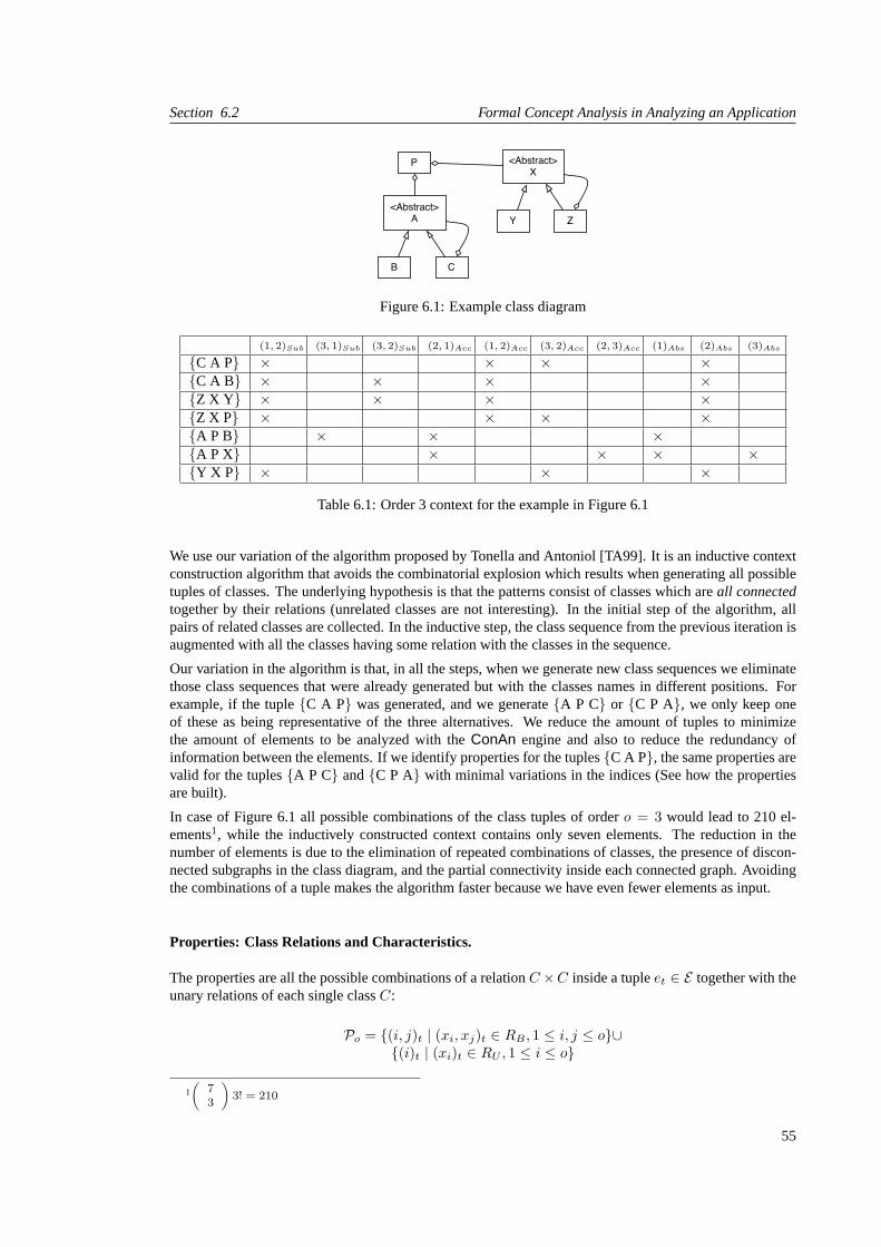
Section 6.2 Formal Concept Analysis in Analyzing an Application
<Abstract>X
Y Z<Abstract>
A
B C
P
Figure 6.1: Example class diagram
(1, 2)Sub (3, 1)Sub (3, 2)Sub (2, 1)Acc (1, 2)Acc (3, 2)Acc (2, 3)Acc (1)Abs (2)Abs (3)Abs
{C A P} × × × ×{C A B} × × × ×{Z X Y} × × × ×{Z X P} × × × ×{A P B} × × ×{A P X} × × × ×{Y X P} × × ×
Table 6.1: Order 3 context for the example in Figure 6.1
We use our variation of the algorithm proposed by Tonella and Antoniol [TA99]. It is an inductive contextconstruction algorithm that avoids the combinatorial explosion which results when generating all possibletuples of classes. The underlying hypothesis is that the patterns consist of classes which areall connectedtogether by their relations (unrelated classes are not interesting). In the initial step of the algorithm, allpairs of related classes are collected. In the inductive step, the class sequence from the previous iteration isaugmented with all the classes having some relation with the classes in the sequence.
Our variation in the algorithm is that, in all the steps, when we generate new class sequences we eliminatethose class sequences that were already generated but with the classes names in different positions. Forexample, if the tuple{C A P} was generated, and we generate{A P C} or {C P A}, we only keep oneof these as being representative of the three alternatives. We reduce the amount of tuples to minimizethe amount of elements to be analyzed with theConAn engine and also to reduce the redundancy ofinformation between the elements. If we identify properties for the tuples{C A P}, the same properties arevalid for the tuples{A P C} and{C P A} with minimal variations in the indices (See how the propertiesare built).
In case of Figure 6.1 all possible combinations of the class tuples of ordero = 3 would lead to 210 el-ements1, while the inductively constructed context contains only seven elements. The reduction in thenumber of elements is due to the elimination of repeated combinations of classes, the presence of discon-nected subgraphs in the class diagram, and the partial connectivity inside each connected graph. Avoidingthe combinations of a tuple makes the algorithm faster because we have even fewer elements as input.
Properties: Class Relations and Characteristics.
The properties are all the possible combinations of a relationC ×C inside a tupleet ∈ E together with theunary relations of each single classC:
Po = {(i, j)t | (xi, xj)t ∈ RB , 1 ≤ i, j ≤ o}∪{(i)t | (xi)t ∈ RU , 1 ≤ i ≤ o}
1
(73
)3! = 210
55

Collaboration Patterns Chapter 6
Each property has one or two indices that refer to the position of the class to be analyzed inside the tuple,and a subindext to indicate the name of the property. For example, the property(3, 2)Sub applied to theelement{C A B}means that the class B is a subclass of the class A. Using indices instead of names allowsdisjunct tuples to share common properties. In the example result (Table 6.2) the tuples{C A B} and{Z XY} have the common properties(1, 2)Sub, (2)Abs, (1, 2)Acc and(3, 2)Sub.
top ( all elementsG, ∅ )8 ( { {C A P}, {Z X P}, {C A B}, {Z X Y}, {Y X P} }, { (1, 2)Sub, (2)Abs })7 ( { {A P X}, {A P B} }, {(2, 1)Acc, (1)Abs } )6 ( { {C A P}, {Z X P}, {C A B}, {Z X Y} }, { (1, 2)Sub, (2)Abs, (1, 2)Acc } )5 ( { {C A P}, {Z X P}, {Y X P} }, { (1, 2)Sub, (2)Abs, (3, 2)Acc } )4 ( { {A P B} }, { (3, 1)Sub, (1)Abs, (2, 1)Acc } )3 ( { {A P X} }, { (2, 1)Acc, (1)Abs, (3)Abs, (2, 3)Acc} )2 ( { {C A B}, {Z X Y} }, { (1, 2)Sub, (2)Abs, (1, 2)Acc, (3, 2)Sub } )1 ({ {C A P}, {Z X P } }, { (1, 2)Sub, (2)Abs, (1, 2)Acc, (3, 2)Acc } )
bottom (∅, all propertiesM )
Table 6.2: Concepts of the example in Figure 6.1
6.2.2 ConAn Engine: Calculation of the Concepts
So far we specified all the prerequisites to start the calculation process of the concepts and lattice. There areseveral algorithms to calculate the concepts and its lattice [SR97]. We use the Ganter algorithm [GW99],because it is one of the most efficient in terms of time performance [KO01].
The example of Figure 6.1 yields ten concepts for the ordero = 3. They are listed in Table 6.2.
To make the explanation easier, let’s see the specific case of a known pattern, such asComposite Pattern[GHJV95]. We can reduce and generalize the structural information to the relationshipsisSubclass, isAb-stractandaccessesand see it as in Figure 6.2. This simplified Composite Pattern is detected twice in theexample of Figure 6.1:{C A B} and{Z X Y} as concept 2.
<Abstract>1
2 n3 . . . . . . .
Figure 6.2: Structural relationships of the Composite Pattern
6.2.3 Concept Lattice: Post Filtering
Once the concepts are calculated, each concept is acandidatefor a pattern. But not all concepts arerelevant. Therefore a post processing of the concepts collection is needed to filter out concepts that are notmeaningful. Let’s look at the different filters.
Graph Representation of the Concept Intent.
To clarify the definitions, we introduce the graph representation of the intent of a concept. This graph isspecific to our domain and cannot be applied to general FCA.
56

Section 6.2 Formal Concept Analysis in Analyzing an Application
Intent relation graph: An intent relation graphis a graph whose nodes are the indices of the propertiesof the binary relationRB and whose edges are binary relationsRB between the indices.
Nodes = {ni | 1 ≤ i ≤ o}
Edges = {(ni, nj) | (i, j) ∈ RB}
Considering Table 6.2, the binary relations of concept 2 are(1, 2)Sub, (1, 2)Acc and(3, 2)Sub, of concept4 are(3, 1)Sub and (2, 1)Acc; and of the concept 8 is(1, 2)Sub. Thus, the intent graphs of concepts 2,4 and 8 are shown in Figure 6.3. Considering the first diagramc2, the edge between node 1 and node2 represents the property(1, 2)Sub or (1, 2)Acc and the second edge between node 2 and 3 is from theproperty(3, 2)Sub. Similarly, we build the graph of concepts 4 and 8. The edges are unlabeled and haveno weights. As soon as at least one relation between two nodes holds, the edge exists. Note that the edgesfrom the intent relation graph are not related to the lattice edges.
1
2
3
1
2
3
1
2
3
c2 c4 c5
Figure 6.3: The intent graph of concepts 2, 4 and 8 of Table 6.2
Removing Disconnected Patterns.
A concept is meaningful when the intent (all properties which are true for this concept) is a set of struc-turally connected nodes.
Connected Pattern:A connected patternis a pattern whoseintent relation graphis connected.
Disconnected patterns are determined by a lower order context. A context of the ordero is computed, whenordero patterns are looked for, whileo − 1, o − 2, · · · order contexts suffice for lower order patterns. Inthe example result (Table 6.2) the following concepts are disconnected: 6, 7, 8 and the top concept.
Merging Equivalent Patterns.
Suppose we have a system with the classes as shown in Figure 6.4. It might then happen that during theconcepts and lattice calculation, we find the two concepts shown in Table 6.3.
D
E F
S
T U
Figure 6.4: Adapter Pattern with two sets of classes
c1 ({ {D E F} }, { (2, 1)Sub, (3, 2)Acc} )c2 ( { {T U S} }, {(1, 3)Sub, (2, 1)Acc } )
Table 6.3: Concepts of the example in Figure 6.4
57

Collaboration Patterns Chapter 6
Even though{D E F} and{T U S} are exactly the same pattern, the algorithm treats them separately. Thishappens because when generating the class sequences, we just keep one representative of each possiblecombination of classes. This means we just look at{D E F} which represents the class sequence{{D FE}, {E D F}, {E F D}, {F D E}, {F E D}}.Equivalent Patterns: Two concepts, representing collaboration patterns, areequivalentif a permutation ofthe indices of the intent properties exists such that each property from the first concept can be transformedinto a property of the second concept by that permutation, and vice versa [TA99].
In our example we find a permutationα = {3 7→ 1, 1 7→ 2, 2 7→ 3}, which transforms the tuple:{T U S}α7−→ {S T U}. Conceptc2 (from Table 6.3) can now be removed when the translated extent of this concept
is added on conceptc1. We call this process asmerging equivalent patterns.In the main example (Table 6.2) concepts 4 and 5 are equivalent: The permutationα = {3 7→ 1, 2 7→1, 3 7→ 2} translates the properties of concept 5 into those of concept 4.
Applying these two filters (removing disconnected patternsandmerging equivalent patterns) on the mainexample leads to the four patterns presented in Table 6.4. The first three patterns are directly taken from thefirst three concepts. Patternp4 is merged from concepts 4 and 5. The elements of concept 5 are translatedinto {P C A}, {P Z X} and{P Y X}, and are appended to{A P B}.
p4 ( { {A P B}, {P C A}, {P Z X}, {P Y X}}, { (3, 1)Sub, (1)Abstr, (2, 1)Acc } )p3 ( { {A P X} }, { (2, 1)Acc, (1)Abstr, (3)Abstr, (2, 3)Acc} )p2 ( { {C A B}, {Z X Y} }, { (1, 2)Sub, (2)Abstr, (1, 2)Acc, (3, 2)Sub } )p1 ({ {C A P}, {Z X P } }, { (1, 2)Sub, (2)Abstr, (1, 2)Acc, (3, 2)Acc } )
Table 6.4: Resulting Patterns after the merging of equivalent patterns from the concepts of Table 6.2
Guessing Names for Patterns.
Some of the detected patterns might structurally match known Design Patterns. To check this, we need alibrary of named reference patterns. In our approach, we provide this library by programming concreteinstances of patterns. For the Composite Pattern an instance with the properties(1, 2)Sub, (2)Abs, (3, 2)Acc
and(3, 2)Sub for the ordero = 3 is stored as a reference pattern (compare Figure 6.2). Thus patternp2
from our example is recognized as an instance of the Composite Pattern.
6.2.4 Pattern Neighborhood
One of the advantages of the FCA approach is that the generated concepts are related within acompletepartial order. Thus given a conceptc, we can identify thecover conceptandsubordinate conceptof c. Acover conceptin the lattice has less properties thanc; and asubordinate conceptin the lattice has moreproperties. Looking at the lattice, if a conceptc has a cover conceptsp, sp is higher up thanc. Similarly,if a conceptc has a subordinate conceptsb, sb is lower thanc in the lattice. With these two definitions, wedefine the idea ofneighborhood. We define two kinds of neighbours. Considering that each conceptc is apotential pattern, we define:
Almost pattern: An almost pattern Xof a patternY is a patternX which is contained in the cover conceptof the patternY in the lattice.
Overloaded pattern: An overloaded pattern Xof a patternY is a patternX which is contained in thesubordinate of a patternY in the lattice.
As a generic example, Figure 6.5 shows the structure ofalmostand overloadedpatterns of a conceptrepresenting the structure of aComposite Pattern.
In the lattice of the example (shown in Figure 6.6), we see that concept 5 is an almost pattern of concept 1.For example, tuple{Y X P} is missing the property(1, 2)Acc, so belongs to concept 5 instead of concept 1.
58

Section 6.2 Formal Concept Analysis in Analyzing an Application
3
<Abstract>2
1
{ C A B }
O = 3
3
<Abstract>2
1
3
2
1
Figure 6.5: Almost and overloaded patterns of a Composite Pattern
87
3 4 65
21
Bottom
Top
{C A B}{Z X Y}
{C A P}{Z X P}
{Y X P}
{A P B}
{A P X}
2 accesses 11 isAbstract
1 isSubclassOf 22 isAbstract
3 accesses 2
1 accesses 2
3 isSubclassOf 2
3 isSubclassOf 1
3 isAbstract2 accesses 3
Figure 6.6: Resulting lattice of Incidence Table 6.1
But the problem with our concrete approach is that the side-effect of havingequivalent patternshas to betaken into account here as well. As we have seen concept 4 is equivalent to concept 5. This new concept(from the union of concepts 4 and 5) has two main consequences:
• the union of concepts 4 and 5 is now an almost pattern of concept 1
• new connections with other concepts can appear. In this specific case, if we translate the propertiesof concept 2 with the permutationα = {1 7→ 3, 2 7→ 1, 3 7→ 2}, we see that this transforms theunionof the concepts 4 and 5 in an almost pattern of thenewconcept 2 considering the intents of theconcepts. But the union of the concepts 4 and 5 have to add thetransformedelements of the extentof concept 2. Thus the elements ofp2 have to be added inp4: {C A B} α7−→ {A C B} and{Z X Y}
α7−→ {X Z Y}.
After the post-filtering process, where we modify the extent of some concepts, findingequivalent patternsand removingdisconnected patterns, we no longer have a valid lattice, but simply apartial order [DP02].Now the patterns have reached their final state and are listed in Table 6.5.
59

Collaboration Patterns Chapter 6
p4 ( { {A P B}, {P C A}, {P Z X}, {P Y X}, {A C B}, {X Z Y}},{ (3, 1)Sub, (1)Abstr, (2, 1)Acc } )
p3 ( { {A P X} }, { (2, 1)Acc, (1)Abstr, (3)Abstr, (2, 3)Acc} )p2 ( { {C A B}, {Z X Y} }, { (1, 2)Sub, (2)Abstr, (1, 2)Acc, (3, 2)Sub } )p1 ({ {C A P}, {Z X P } }, { (1, 2)Sub, (2)Abstr, (1, 2)Acc, (3, 2)Acc } )
Table 6.5: Final Patterns after applying the post filters to the concepts from Table 6.2
Linking Different Orders.
Almost and overloaded patterns remain in the same ordero. There are as well related patterns when wecalculate the lattice for the ordero−1 and the ordero+1. Patterns in a higher order have subpatterns fromthe lower order. They can be detected by subgraph matching techniques.
Cover pattern: C2 is a cover patternof the patternc1, if the intent relation graphof the patternc1 is asubgraph of the intent relation graph ofc2.
Cover patterns are the connection links to the patterns in the ordero + 1.
Subpattern: C2 is asubpatternof the patternc1, if the intent relation graphof the patternc2 is a subgraphof the intent relation graph ofc1.
Subpatterns are the connection links to the patterns in the ordero − 1. Linking the different orders of thepatterns is madeafter applying the post processing filter.
3
<Abstract>2
1
<Abstract>2
3
<Abstract>2
1
4
{ C A B P }
3
<Abstract>2
1
{ C A B }
{ A B } { C A }
O = 4
O = 3
O = 2
Cover Pattern
Sub Patterns
Figure 6.7: Sub and cover patterns of the Composite Pattern (p2)
Figure 6.7 show the subpatterns of the Composite Patternp2 in the lower ordero = 2, and the cover patternin ordero = 4.
The pattern neighborhood is now the union of all the above mentioned sets:
Pattern Neighborhood: A pattern neighborhoodof a patternc is the union of the almost, overloaded,cover and subpatterns of the patternc.
60

Section 6.3 Validation: Case Studies
The approach of Antoniol and Tonella [TA99] deals with patterns as isolated entities. With our approach werelate the patterns within the same lattice and also with other patterns calculated in higher and lower orders.Thus, we are able to analyze not only the detected patterns but also the relationships to other patterns in theapplications.
6.3 Validation: Case Studies
We have validated our approach by applying the tool we have implemented calledConAn PaDito threemid-sized Smalltalk applications: ADvance, SmallWiki and CodeCrawler.
• ADvance2 is a system round-trip engineering tool from IC&C. It is a multidimensional OOAD-toolfor supporting object-oriented analysis and design, reverse engineering and documentation. AD-vance is as well integrated in our toolConAn PaDito show the structure of the found patterns visu-ally.
• SmallWiki 3 is a new and fully object-oriented wiki implementation in Smalltalk. It is highly cus-tomizable and easily extensible with new components, appearances, servers, storage, etc.
• CodeCrawler is a language independent software visualization tool4. CodeCrawler supports reverseengineering through the combination of metrics and software visualization [Lan03].
Table 6.6 gives an overview of the size and processing time for each case study. We have applied theapproach as outline in section 6.2 to each case study. After the concepts have been generated, we needa way to classify the patterns to analyze the applications. Thus we classify the patterns in terms of theproperties that are used to describe them. We have built twoClassifiers AandB. TheClassifier Acontainsthree properties:isSubclass , hasAsAttribute , isAbstract and theClassifier Bcontains twoproperties:isSubclass , hasAsAttribute (Table 6.7).
Thus, for example, we take theClassifier Band we get all the patterns that can be described with a setof properties that includeisSubclass or hasAsAttribute . In the specific case of CodeCrawler inorder= 3, we get 14 patterns which are distributed in 300 tuples of classes in total (Table 6.8). This meansthatClassifier Bgives us an average of 21 tuples per pattern (300 / 14).
ADvance SmallWiki CodeCrawlerClasses 167 100 81Methods 2719 1072 1077Lines of code 14466 4347 4868Computation time ∼2 days ∼2 hours ∼30 min
Table 6.6: Statistical overview of the cases
Classifier A Classifier BisSubclass isSubclass
hasAsAttribute hasAsAttributeisAbstract
Table 6.7: Used Classifiers
The complete analysis of the quantitative impact of the classifiers is shown in the Table 6.8. A classifierwith less properties gives a clearer image of the situation. ApplyingClassifier Bwith less propertiesheavily reduces the number of different patterns whereas the found patterns in total are much less reduced.
2http://www.io.com/∼icc/3http://c2.com/cgi/wiki?SmallWiki4http://www.iam.unibe.ch/∼scg
61

Collaboration Patterns Chapter 6
This leads to patterns which have more tuples as elements. The patterns ofClassifier Aare too “noisy”.Comparing again the case of CodeCrawler in order=3, we get that theClassifier Ahas an average of 13tuples per pattern (431 / 32) meanwhile theClassifier Bhas an average of 21 tuples per pattern (300 / 14).
ADvance SmallWiki CodeCrawlerClassifier Classifier Classifier
o A B A B A B
2 # different patterns 12 5 8 4 7 3# patterns in total 215 181 138 114 116 85
3 # different patterns 57 32 37 17 32 14# patterns in total 1103 907 471 402 431 300
4 # different patterns 329 218 190 93 110 58# patterns in total 7521 6093 2293 2039 1423 983
Table 6.8: Classifier statistics
With 34 core classes of CodeCrawler we analyzed patterns of higher ordero > 4. The statistics are inTable 6.9. Unfortunately this calculation takes one week on a PC.
ordero 2 3 4 5 6 7
# different patterns 6 24 64 157 335 650# patterns in total 45 94 209 461 954 1850
Table 6.9: Patterns of higher order of a set of core classes from CodeCrawler
To better compare the three cases we selected eight reference patterns which are introduced in Table 6.10.Subclass Staris a tuple where one class has all the others as subclass. In theSubclass Chainthe classesform an inheritance chain, whereas in theAttribute Chainthe classes form an access chain.Attribute Starisa pattern with a class which is used as attribute in all the other classes from the tuple. The next four patterns(Facade, Composite, AdapterandBridge) have all names from the collection of Gamma et. al.[GHJV95].It is important to see that they are simplified to the used structural definitions of inheritance, aggregationand abstractness of a class. If our tool identifies a found pattern with such a reference pattern it just meansthat itcouldbe a candidate for this pattern. The letter A in a box means that the class should be abstract.
Table 6.11 shows all the found patterns of those eight references for the ordero = 2, 3, 4. Most of thepatterns appear twice: Once in the first line (e.g.,, Composite) where the reference pattern lacks the propertyisAbstract; whereas in the second line theisAbstractproperty is taken into consideration. As Classifier Bhas no propertyisAbstractit is obvious that no patterns containing anisAbstractproperty can be found.
One interesting observation is the two zeros marked with a star:Subclass ChainandAttribute Chainofordero = 4 of the CodeCrawler application. Applying Classifier A noSubclass ChainnorAttribute Chainof ordero = 4 is found. Nevertheless Classifier B detects 12 instances ofSubclass Chainand 15 instancesof Attribute Chain. Classifier A does not detect those patterns because CodeCrawler has no chain with anabstract classexactlyat the beginning and the rest of the chain consisting of non abstract classes. Just onerepresentative with an abstract class on top would be enough that the FCA approach would detect the restof the 12 (resp. 15) patterns. This effect shows that having too many properties can be counterproductiveand the basic patterns cannot be detected because there is too much noise.
6.4 Application of the Approach: Analysis
In Chapter 3, we have discussed the approach in general terms. We have also mentioned different issues thatthe user must take into account when applying the approach. Here following we list the issues concerningCollaboration Patternson complete applications.
• Choice of Elements and Properties.Elements are tuples of classes built from the metamodel. As
62

Section 6.4 Application of the Approach: Analysis
o = 3 o = 4Subclass Star
A A
Subclass Chain
A A
Attribute Chain
A A
Attribute Star
AA
Facade
AA
Composite
A A
AdapterA
Bridge
A A
Table 6.10: Structure of investigated patterns
our case study refines the work of Tonella and Antoniol [TA99] we use the same idea to build theelements. The choice of properties is the set of the structural relationships to characterizeStructuralDesign Patterns[GHJV95]. Except the propertiesis subclass ofand is abstractthat are mappeddirectly from the metamodel, the rest of properties are computed from the metamodel.
• Compact Representation of Data.This issue is related to how the tuples of classes are generated. Weavoid generating all permutations of class sequences in the tuples. For example, if the tuple{C A P}is generated, and we subsequently generate{A P C} or {C P A}, we only keep one of these as beingrepresentative of all three alternatives.
63

Collaboration Patterns Chapter 6
ADvance SmallWiki CodeCrawlerClassifier Classifier Classifier
o Pattern A B A B A B
2 Subclasses 95 95 84 84 57 57Attributes 80 80 28 28 26 26
3 Subclass Star 271 271 118 118 140 140Abstract Subclass Star 46 - 12 - 22 -
Subclass Chain 44 44 62 62 28 28Abstract Subclass Chain 10 - 10 - 11 -
Attribute Chain 108 108 39 39 25 25Facade 214 214 23 23 42 42
Abstract Facade 0 - 0 - 15 -Attribute Star 44 44 24 24 9 9
Abstract Attribute Star 3 - 3 - 1 -Composite 6 6 0 0 0 0
Abstract Composite 2 - 0 - 0 -Adapter 32 32 13 13 4 4
Abstract Adapter 13 - 1 - 1 -Bridge 37 37 44 44 19 19
Abstract Bridge 6 - 5 - 12 -4 Subclass Star 1073 1073 135 135 313 313
Abstract Subclass Star 87 - 5 - 15 -Subclass Chain 12 12 31 31 0∗ 12
Abstract Subclass Chain 1 - 10 - 3 -Attribute Chain 137 137 46 46 0∗ 15
Facade 627 627 13 13 56 56Abstract Facade 0 - 0 - 20 -Attribute Star 15 15 22 22 0 0
Abstract Attribute Star 1 - 3 - 0 -Composite 3 3 0 0 0 0
Abstract Composite 1 - 0 - 0 -Bridge 20 20 43 43 6 6
Table 6.11: Investigated Patterns
• Multiple Contexts.In this case, we have used 3 lattices. Each lattice is for one order of the elements:2, 3 and 4. All of them use the same set of properties.
• Performance of the Algorithm.With the tuples of classes of order more than 4, we are not able tohave a reasonable computation time of the algorithm. With one of the applications using tuples ofclasses of order 4, the computation time took around 2 days and this is not acceptable time from ourviewpoint to software engineering.
• Meaningless Concepts.As we said previously, each concept is a candidate for a pattern. In this case,each concept represents a graph in which the set of the elements is the set of nodes, and the set ofproperties define the edges that should connect the nodes,e.g., if (A P C) has the propertiesA issubclass of PandP uses C, then we have a graph of 3 nodes with edges from A to P and from P toC. Thus we discarded all the concepts that represent graphs in which one or several nodes are notconnected at all with any node in the graph.
• Mapping Partial Order of the Lattice.In this case, we map the partial order of the lattice to thedefinition of neighborsof a pattern. We can detect either missing relationships between classesneeded to complete a pattern, or excess relationships between classes that extend a pattern.
• Limits of Collaboration Patterns. In this high level view, we consider that there are still possible newcollaboration patterns to detect when applying the approach in other applications.
64

Section 6.5 Discussion
6.5 Discussion
Based on the results, we are able to evaluate our approach from different viewpoints:
Locate and understand relations such as inheritance, accesses and invocations:The filtering possibil-ities ofConAn PaDiare useful to have a look at one single class or a set of classes. Our tool is adequate tofind out the relations of those filtered classes. For example we have a look at the CodeCrawler application:Just looking at the patterns containing the classCCNodePlugin we see that the following classes arerelated with this class:CCItemPlugin , CCCompositeNodePlugin , CCFAMIXNodePlugin areinheritance relations. There are no attribute relations.
Detect class dependencies:As all the different relations (inheritance, access, invocation) are shown, thedependencies derived from those relations are then available. Looking again at CodeCrawler, we see thate.g.,, the classCCTool cannot have a lot of dependencies because this class is in none of the patterns,whereasCCNodePlugin is in 47 patterns up to ordero = 4 and must therefore have several dependencies.
Identify the possible presence of classical design patterns:Candidates for classical design patterns arefound. Some of these turn out to befalse candidates, i.e., structural patterns which superficially resembledesign patterns, but are not in fact instances of those design patterns. The reasons for the misinterpretationare:
• Not all the properties are absolutely reliable. For example, the extraction of the type of an attributeis based on a heuristic [Aeb03], because we work with Smalltalk, which is a dynamically typedlanguage
• The collaborations of the detected structural patterns match that of the known design pattern, but notits intent. This happens mainly with theFacade, AdapterandBridge patterns in our case studies.Consider, for instance, theBridgepattern of ordero = 3 in Table 6.10. A class that has a subclassand accesses another class is acandidatefor a Bridge, but there is no guarantee that such a class isactually serving the purpose of aBridge.
To decide which are real classical design patterns, detailed knowledge about the application is needed. Itcannot be decided with the information provided byConAn PaDi. We were just able to detect structuralDesign Patterns such as:Adapter, Bridge, Composite, or Facade. We could just detect these patternsbecause we have primarilystructural information about the entities (classes, methods, attributes,etc).Extracting only structural information is not enough to infer behavioral patterns [TA99].
Identify the neighborhood of a pattern: The neighborhood can be analyzed by navigating through thealmost, overloaded, sub and cover pattern. This can be important to detect all candidates for a classical pat-tern. For example, we consider theAbstract Compositepattern of ordero = 3 of the ADvance application.Applying Filter A ConAn PaDidetects twoAbstract Compositepatterns, but in the neighborhood we findfour moreCompositepatterns without an abstract composite root.
Find candidate classes for restructuring:In our case studies we could not find a candidate for restructur-ing, because our analysis was made using only structural information. In general, control flow informationand detailed information about the method bodies is needed to detect candidates for restructuring [Tic01].Furthermore a lot of domain specific knowledge is needed. Nevertheless we believe that future investi-gation with our tool such a detection is possible, when the above mentioned information is available andtaken into consideration.
Mining patterns: As our approach with FCA detectsany kind of patterns we found plenty of “new”patterns, meaning that they are not referred to in the literature. Whether those patterns are useful and makesense as Design Patterns is another issue. If we see in Table 6.8 the case study ADvance for the ordero = 4,we detect 329 different patterns. The frequency of several patterns is shown in Table 6.11. We see that theFacadeis detected 627 times and theBridgeonly 20 times. The accumulated elements of the pattern areshown again in Table 6.8. All the elements of all the patterns for ordero = 4 of the ADvance applicationis 7521. A reason for this high amount of patterns is: if we consider that an application has a classC0 withfive subclassesC1..5. In the ordero = 5 aSubclass Starwill be detected once. But for example in the order
65

Collaboration Patterns Chapter 6
o = 3, our approach detects 10 subclass stars:{C0C1C2}, {C0C1C3}, {C0C1C4}, · · · , {C0C4C5}.
CCItem
CCNode CCEdge
CCItemPlugin
CCNodePlugin CCEdgePlugin
CCItemFigureModel
CCNodeFigureModel CCEdgeFigureModel
Figure 6.8: ThreeSubclass Starsof CodeCrawler
Understand the class roles:Using the information gained about the class relations it is possible to guessits role. In CodeCrawler we detect in the ordero = 3 threeSubclass Starsshown in Figure 6.8. Theassumption that these are three parallel structures cooperating together are proved by future investigation.
Identify coding styles: We have seen that frequency and the existence of a pattern in a system is besidesdomain specific issues, as well an issue of coding style. In our case studies we have seen that CodeCrawlerhas a lot ofSubclass StarandFacade, whereas SmallWiki has a lot ofAttribute ChainandAttribute Stars.ADvance is the only application with theCompositepattern.
6.6 Related Work
The starting point for our work was the approach of Tonella and Antoniol [TA99], and we have summarizedour improvements to their approach in Section 6.2. Other related work focuses on the detection of designpatternsa la Gammaas opposed to more generalsoftwarepatterns. We cite some of these approaches.
Brown [Bro96] presents in his Masters thesis a tool to detect design patterns in Smalltalk environments. Heexplains how to deal with the typeless language Smalltalk. The detection itself is then based on Corman’scycle-detection technique [CLR90]. There is no general abstraction proposed to encode patterns. In par-ticular, Brown does not demonstrate a clearly generalizable approach to detect patterns: for each pattern, aspecialized detection algorithm must be developed.
Seemann et. al. [SvG98] use a compiler to generate graphs from the source code. This graph acts as theinitial graph of a graph grammar that describes the design recovery process. The validation is made withrespect to well-known design patterns such asCompositeandStrategyin the Java AWT package.
Keller et al. [KSRP99] present an environment for the reverse engineering of design components based onthe structural descriptions of design patterns. Their validation is made with SPOOL on three large-scaleC++ software systems. They store the Meta-Model as UML/CDIF and query then this model for patterns.
Niere et al. [NSW+02] provide a method and a corresponding tool which assist in design recovery andprogram understanding by recognizing instances of design patterns semi-automatically. The algorithmworks incrementally and needs the domain and context knowledge given by a reverse engineer. To detectthe patterns they use a special form of annotated abstract syntax graph (ASG). Using a subgraph matchingalgorithm allows them as well to define a pattern neighborhood as we gain out of the lattice. An evaluationof the approach is made with the Java AWT and JGL libraries.
In Kramer and Prechtel’s approach[KP96], the patterns are stored as Prolog rules. Their Pat tool takes themeta-informa–tion directly from the C++ header files and queries them. The validation on the C++ libraries
66

Section 6.7 Conclusions
shows that the precision is around 40 percent.
Albin-Amiot et al. [AACGJ01] show how to automate the instantiation and detection of design patterns. Tocope with these objectives, they define aPattern Description Languageto describe design patterns as first-class entities. Thus they can manipulate and adapt design patterns models to generate source code. With thesame language, and a Constraint Satisfaction Problem formalism to detect complete and distorted versionsof design patterns, and with the toolJavaXL(their own tool) they are able to make the distorted versionscompliant with the design patterns models. With this approach, they help OO software practitioners design,understand, and re-engineer a piece of software, using design patterns.
6.7 Conclusions
This section summarizes this approach with a summary, a discussion, the answers to the research questionsproposed in Chapter 2 and future work.
6.7.1 Summary
The complete description of the approach including the analysis of the cases studies and the tool imple-mented to support it is described in [Buc03]. Although our work is based on that of Tonella and Antoniol,there are some notable differences:
• According to our measurements of Tonella and Antoniol’s algorithm, the performance with our datawas a critical issue. We propose an improvement to their algorithm to make it faster. We eliminate theredundancy in the sets of elements considered to reduce the calculation time for the formal contextgeneration. Using as example Figure 6.1 (Section 6.2.1) where there are 7 classes and running onthe same platform, we have made a comparison (shown in Table 6.12) in terms of time performance.
our approach [TA99]order Number
of Tuplestime [s] Number
of Tuplestime [s]
2 6 0.1 8 0.13 7 0.1 18 0.24 6 0.1 34 0.45 6 0.1 70 2.46 4 0.1 140 17.67 1 0.1 140 27.5
total 30 0.6 410 48.2
Table 6.12: Comparison between our inductive approach and the inductive approach from Tonella
In Table 6.12, we see that if we compare our approach to that of Tonella and Antoniol, the calcu-lation time in the different orders is uniform, whereas in their approach it increases for each order.The number of tuples also increase with each order in their approach, whereas it remains relativelyconstant in ours.
• With our improvement in the algorithm where we keep one representative of the set of possiblecombinations of a class sequence, we avoid repeated information and we avoid removingequivalentinstances[TA99] inside the concepts.
• With our approach, we are not constrained to the detection ofdesignpatterns. We are focused on thelarger scope of detecting recurring collaborations patterns implicit in the code, which we refer to ascollaboration patterns. These collaborations may represent design patterns, architectural constraints,or simply idioms and conventions adopted for the system.
67

Collaboration Patterns Chapter 6
• In contrast to Tonella and Antoniol’s approach, we relate the patterns to each other using the connec-tions between the concepts given by the partial order in the lattice, and the lattices calculated withthe differentorders. This is what we namedPattern Neigborhoods. For example, it is possible todetect patterns which arealmostlike another pattern.
• We propose to take the information from a language independent Meta-Model instead from thesource code itself. This makes the approach more general because it can be applied to applica-tions in different programming languages. In contrast, Tonella and Antoniol focus on experimentsdone with C++ applications.
• We separate the calculation of the patterns from the analysis process. This allows us to separatethe time-consuming calculation of the patterns from their analysis. The patterns are stored in arepository, and can be analyzed by applying different classifiers to the results.
• To gain an overview more quickly, as a starting point, we compare the detected patterns against areference library of well-known design patterns in the post-processing phase. This library is incre-mented with new detected patterns with each application we analyze.
6.7.2 Research Questions
Based on the approach, we are able to answer some of the research questions proposed in Chapter 2:
• How does the technique help in discovering patterns introduced in the system ?
In this last approach, we confirm again that the application of FCA is scalable because in this thirdabstraction level we analyze a complete application. Using classes as FCA elements and structuralrelationships as FCA properties, we have identified recurring situations (named asCollaborationPatterns) in a complete application. TheseCollaboration Patternsreveal existing design patterns,coding styles or architectural patterns implemented in the system. With this information, we have acomplete mental model (from the structural viewpoint) of a system, complemented with additionalissues such as classes that are used in all the system, presence of design patterns and classes roles.
• Does the technique discover known and unknown patterns ?
Both kinds of patterns are discovered. The detected design patterns are considered as known patternsand the architectural patterns and coding styles are considered as unknown patterns in our workcontext. The last ones are considered as unknown because in the most of the cases they are notdocumented, and the name of methods of involved classes do not provide useful information. In thecase of design patterns, in spite that it can be implemented without following naming convention,they can be characterized by a specific set of properties.
• How do the patterns help to understand a system ?
This question is related to the first one. As we have said previously, with the identified patterns we geta complete mental model (from the structural viewpoint) of a system complemented with additionalissues such as related patterns, classes that do not participate in any pattern and used coding styles.
6.7.3 Future Work
Enhance the model with information at a higher abstraction level.Instead of only using the structuralinformation, we could use properties of an higher abstraction level. Such higher-level information couldinclude properties like: isLeaf, isComponent, isFacade. Among the resulting patterns, behavioral patternsmight be inferred.
Solve the scalability problem. In an industrial environmentConAn PaDiwould be considered to be tooslow. Results should be available in real time or at least within seconds, otherwise the developer will notuse this tool. One idea to improve the speed is not to take all orders into consideration. Figure 6.9 showsapproximately the expected found patterns in correlation with the order. We suppose that we just calculate
68

Section 6.7 Conclusions
Figure 6.9: Unproblematic orders for calculation
the patterns before and after the peak of the curve. We expect that the patterns for the lower orders areinteresting to analyze the dependencies and those for bigger orders are interesting to understand the rolesand gain an overview of an application.
Improved name guessing.Use a better reference library to detect well-known patterns and improve thematching algorithm,i.e., make the matching algorithm more fuzzy.
69


Chapter 7
Conclusions
The last chapter summarizes the main features, the answers to the research questions proposed in Chapter 1,the main lessons learned, and future work related to the approaches developed in this thesis.
7.1 Summary
In this thesis we present a general approach for applying FCA in reverse engineering of object-orientedsoftware. We also evaluate the advantages and drawbacks of using FCA as a metatool for our reverseengineering approaches.
We also identify the different bottlenecks of the approach. Thus, we are able to focus clearly on solvingwhich and where the limitations appear (if there are some possible solutions) to draw the maximum benefitoffered by FCA.
From our tool builder viewpoint, we have proven that FCA is an useful technique to identifygroupsofsoftware entities with hidden dependencies in a system. With FCA, we have built different software en-gineering tools that help us to generatehigh level viewsat different levels of abstraction of a system. Wegenerate thehigh level viewsbecause without them, thesoftware engineershould be obliged to read thelattice. This can represent a problem because in most of the cases, besides the useful information, thelattice can also have useless information that can introducenoisein analyzing a system.
7.2 Research Questions
Based on the approach, we are able to answer some of the research questions proposed in Chapter 1:
• Do we understand how the system is implemented? What are the constraints or limits imposed in thesystem?
We have shown in this thesis that the differenthigh-level views (XRay viewsat class-level,Hi-erarchy Schemasat class hierarchy-level andCollaboration Patternsat system-level) makehiddendependencies asexplicitones. These dependencies reveal the different existing contracts between thedifferent (groups of) software artifacts in a system. Depending on the abstraction level of the systemwe analyze, with the high-level views we identify different characteristics in a system. Just to men-tion some of them, for example, we identify group of collaborating methods at class-level, misuse ofinheritance mechanisms at class-hierarchy or use of patterns at the application level. We believe thateach view provides enough (but not yet complete) information to generate the first fingerprints of asystem.
71

Conclusions Chapter 7
• How can we detect implicit unanticipated dependencies?
When defining adequate properties in a FCA context (in the iterativemodellingprocess of elementsand properties shown in Chapter 3), the combination of them (intents of concepts) are the potentialsources of information to detect implicit dependencies. Once we have applied thePost-Filteringprocess (shown in Chapter 3), the resulting concepts are those that show meaningful implicit unan-ticipated dependencies.
• How are the mechanisms such as polymorphism and inheritance used in the system?
In Hierarchy SchemasandCollaboration Patterns, we have analyzed inheritance as a building mech-anisms in a system. In Hierarchy Schemas we have shown we can identifygood, badandirregularsituations of the use of inheritance relationship. In spite that this relationship defines a contract be-tween several classes in terms of ais-a relationship, we have seen that the misuse of this mechanismcan producenoisein a class hierarchy. Thebadandirregular cases reveal us for example, violationof class encapsulation or bad reuse of behavior of parent classes. In the case ofCollaboration Pat-terns, the inheritance mechanism was used in combination of other properties to identify patterns.Half of the identified patterns included the inheritance relationship, meaning that it represents anoften-used mechanism in a system.
In the case of polymorphism, this characteristic was not a main aspect in our analysis, meaning thatwe did not use it as a defined property in our contexts. The use of polymorphism is part of theanalysis of systems in future work.
• How can we discover defects introduced in the systems?
Discovering defects in systems in our approach depends also in identifying adequate properties. Thecombination of properties in all the approaches helps us to reveal good as well as bad situations ina system. This case is proven in the case of hierarchy schemas where we identify classes that wereusing the state of superclasses without using the accessors, and consequently violating the superclassencapsulation.
• How can we discover recurring situations (“patterns-like”) of dependencies in the systems?
When using FCA, a concept reveals us a set of elements that share a set of properties. The mostmeaningful concepts are those that have a significant number of elements. These concepts then showthat we have a number of software artifacts that share some commonalities, that we consider them aspatterns. They represent recurring situations appearing in a system.
• Is the mental model generated by “high-level views ” meaningful enough (in terms of information)to understand the system?
As we have said in the first answer, we believe that each view provides enough (but not yet complete)information to generate the first fingerprints of a system. We think that we still need more case studiesin each approach to identify which are the missing characteristics in a system to get a more completefirst mental model of a system.
• Which are the advantages and disadvantages of using a clustering technique such FCA as a meta-tool?
In the next section of this chapter, we have summarized which are the advantages and disadvantagesof using FCA as a metatool. Among the main issues, we consider that there are three ones worthmentioning:
– The different bottlenecks produced by the computation times of the algorithms and building theFCA elements and properties can compromise the success or fail of an experiment.
– The noise produced by the amount of concepts can bring useless information for our ap-proaches.
– The combination of properties help us detect unanticipated dependencies revealinghiddencon-tracts between different software artifacts. This was the most valuable information in our ap-proaches.
72

Section 7.3 Lessons Learned
7.3 Lessons Learned
In general terms, we have seen that Formal Concept Analysis is a useful technique in reverse engineering.From our experiencies [Are03, ABN04, ADN03] in developing this approach, several lessons learned areworthwhile mentioning.
Lack of a general methodology.The main problem we have found in the state of the art is the lack of ageneral methodology for applying FCA to the analysis of software. In most publications related tosoftware analysis, the authors only mention the FCA mapping as a trivial task, and how they interpretthe concepts. With our approach, we achieved not only to identify clear steps for applying FCA to apiece of software but where we have identified different bottlenecks in using the technique.
Modelling software entities as FCA components.The process of modelling software entities as FCAcomponents is one of most difficult tasks and we consider it as one of the critical steps in the ap-proach. Modelling is an iterative process in which we map software entities to FCA components,and we test whether they are useful enough to provide meaningful results. This task is not trivial atall, because it entails testing at least 5 small case studies (which should be representative of largercase studies) in each developed approach. Each case study should help to refine the building ofFCA components to obtain meaningful concepts. Thus, this process can be considered as incremen-tal step-by-step one. Obviously, we can conclude after the initial experiments that the chosen FCAcomponents are not the most adequate and discard the complete FCA mapping, and start the processfrom the scratch.
Performance of FCA algorithms. Computation Time The performance of the algorithms (to build theconcepts and lattice) was one of main bottlenecks. In small case studies, this factor can be ignoredbecause the computation time is insignificant. But in large case studies this factor can cause thecomplete approach to fail because computing the concepts and the lattice may take several hours(eventually days) and this is not a acceptable time to do some software analysis.
Performance of FCA algorithms. Implementation The computation time of the FCA algorithms is alsoaffected by how they are implemented in a chosen language. A direct mapping of the algorithms (inpseudo-code, as they are presented in books) to a concrete programming language is not advisable.In our specific case, we took advantage of efficient data structures inSmalltalklanguage to representthe data and improve the performance of the algorithms.
Supporting Software Engineers.The result of our experiences must be read by software engineers. Onepositive issue in this point is that with the high level views the software engineer is not obliged toread the concept lattices , meaning that he needs not be a FCA expert. Our approach is not focused onend-users. We would need a new abstraction level over the approach with a more friendly softwareinterface.
Interpretation of the concepts. Although we can have an adequate choice of FCA elements and proper-ties, the interpretation of the concepts is a difficult and consuming-time task to achieve. In most ofthe cases, we have tried to associate a meaning (a name) to each concept based on the conjunction ofits properties. This task must be done by a software engineer applyingopportunistic code readingtoget meaningful interpretations. It is difficult to discover which combination of properties are or notuseful. This process is completely subjective because it depends on the knowledge and experienceof the software engineer.
Use of the Complete Lattice.Not all the concepts have a meaning in our approach, so we do not use thecomplete lattice in our analysis. In most of the cases, we remove meaningless concepts becausefrom software engineering viewpoint they did not provide enough information for the analysis. Wehypothesize that in certain cases it may be possible to use the complete lattice, but we did not findany.
73

Conclusions Appendix
Use of the Partial Order. Another critical factor is the interpretation of the partial order of the lattice interms of software relationships. Only inCollaboration Patternswe were able to obtain a satisfactoryinterpretation of the partial order. Thus we can conclude that the interpretation is not a trivial task.
Metamodel Information. The results can only be good and complete as the information from the meta-model is. When the input for FCA is already not complete or reliable, the percentage of uselessresults can be higher.
7.4 Future Work
The future work is focused on several research directions, that consist mainly of:
• Analysis of a system using other abstraction levels to analyze how useful the developed approach is.
• Refinements and improvements in the approach to adapt it to new abstraction levels of analysis of asystem.
• Tests with other concept and lattice building algorithms to compare (and eventually improve) theexisting computation time of theConAn engine.
• Development of a measurements framework to measure the different concept and lattice buildingalgorithms based on the used data in our approach.
• Analysis of the partial order of resulting lattices to get possible mappings in terms of software engi-neering relationships.
• Adding more domain information to the existing approaches to evaluate if they can provide moreinformation about the analyzed applications.
74

Appendix A
ConAn Framework
A.1 Introduction
To validate the application of Formal Concept Analysis in generatingHigh Level Views, we have built threetools based on a framework named asConAn. The name is an acronym forConceptAnalysis. In thisappendix, we explain in detail which are the different components of the framework.
A.2 The Meta-Model: Moose
The meta information is taken from the FAMIX Meta-Model. This section gives an introduction toMoose,a reengineering environment, implemented in Smalltalk.
In the past few years the Software Composition Group (SCG) at the University of Bern has been involvedin a number of research projects in the field of software re- and reverse engineering. In the FAMOOS1
project European partners came together to build a number of tool prototypes to support object-orientedreengineering.
To avoid equipping the tool prototypes with parsing technology for different programming languages, acommon information exchange model with language specific extensions is specified. This model is namedFAMIX (FAM OOSInformation EXchange Model) [DGLD04][Tic01].
Mooseis a reengineering research platform implemented in VisualWorks [DGLD04][Tic01]. It has beendeveloped during the FAMOOS project to reverse engineer and re-engineer object-oriented systems. Itconsists of a repository to store models of source code. The models are stored based on the entities definedin FAMIX . The software analysis functionality ofMooseis language independent. The FAMIX modelscan be loaded from and stored to files. Apart from the repository, there are other features implemented tosupport reverse engineering activities:
• a parser for Smalltalk code
• an interface to load and store information exchange files
• a software metrics calculation engine
• an interface for additional tools to browse and visualize stored entities
1http://www.iam.unibe.ch/ ∼famoos/
75

ConAn Framework Appendix A
Figure A.1:Moosearchitecture.
A.3 ConAn: a Framework for FCA
ConAn is a general, extensible framework for FCA implemented in VisualWorks 7.0 [Vis03]. Its nameis an acronym forConcept Analysis. It allows the user to define any kind of elements and properties,and calculate the concepts and the lattice. The user can analyze the results provided by the framework.Four GUI tools in this framework support the user:Formal Context Editor, Concepts Viewer, ConceptCrawler andFish Eye Viewer. The framework can be used as a ready-to-use tool with an interactive GUIor as a white-box framework. The second alternative focuses on users who want to integrate FCA in theirapplications. Thus, automated or semi-automated analysis is possible.
A.3.1 Features ofConAn
Two main features distinguish this framework:extensibilityandencapsulation of the mathematical theory.
Regarding theextensibility,
• The framework can be applied to any domain, and it is not limited only to software understanding.
• Any Smalltalk objects can be used as elements or properties. This makes the framework easy toadapt on a specific domain, where the input can be a result from a pre-process.
• New algorithms can be implemented and easily incorporated in the framework
• The user can develop new post-process filters to be able to better analyze the results
• The user is not obliged to restrict himself to the existing tools, new tools can be developed on top ofthe framework.
Regarding theencapsulation of the mathematical theory, the user is never concerned with the mathematicalbackground of the lattice theory, which is the basis of this framework, and is implemented as ablack boxinside the framework. The user only has to know the public interfaces of two classes: the application facadeand the class representing the concepts.
A.3.2 Components ofConAn
The process from the input to the output provided by this framework is defined by 5 phases defined in theFigure A.2 (introduced in Chapter 3)
76
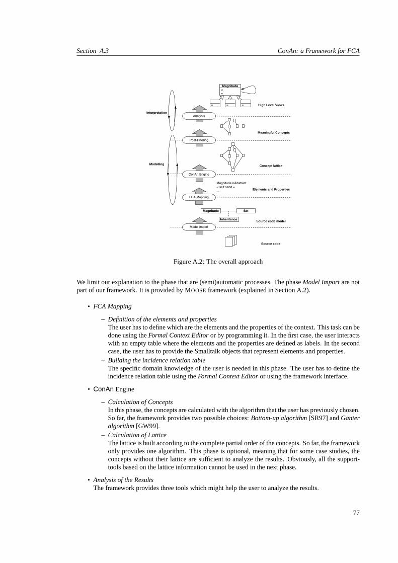
Section A.3 ConAn: a Framework for FCA
Source code
Source code model
Elements and Properties
Magnitude Set
Inheritance
Magnitude isAbstract< self send =...
High Level Views
Magnitude<=
= = =
Concept lattice
Model import
FCA Mapping
ConAn Engine
Post-Filtering
Modelling
InterpretationAnalysis
Meaningful Concepts
Figure A.2: The overall approach
We limit our explanation to the phase that are (semi)automatic processes. The phaseModel Importare notpart of our framework. It is provided by MOOSEframework (explained in Section A.2).
• FCA Mapping
– Definition of the elements and propertiesThe user has to define which are the elements and the properties of the context. This task can bedone using theFormal Context Editoror by programming it. In the first case, the user interactswith an empty table where the elements and the properties are defined as labels. In the secondcase, the user has to provide the Smalltalk objects that represent elements and properties.
– Building the incidence relation tableThe specific domain knowledge of the user is needed in this phase. The user has to define theincidence relation table using theFormal Context Editoror using the framework interface.
• ConAn Engine
– Calculation of ConceptsIn this phase, the concepts are calculated with the algorithm that the user has previously chosen.So far, the framework provides two possible choices:Bottom-up algorithm[SR97] andGanteralgorithm[GW99].
– Calculation of LatticeThe lattice is built according to the complete partial order of the concepts. So far, the frameworkonly provides one algorithm. This phase is optional, meaning that for some case studies, theconcepts without their lattice are sufficient to analyze the results. Obviously, all the support-tools based on the lattice information cannot be used in the next phase.
• Analysis of the ResultsThe framework provides three tools which might help the user to analyze the results.
77

ConAn Framework Appendix A
The following paragraphs introduce the three tools from theConAn framework which support the user inanalyzing the results:
• Concepts ViewerThis tool allows the user to see the elements and the corresponding properties. It is also possible tosee the intent and the extent of each concept, and its subordinates and cover concepts.
• Concept CrawlerThis tool allows the user to display the lattice as a graph. The user can see the intent and extent ofeach concept, or a reduced version where all the elements and properties are just appearing once.One additional feature of this tool is the possibility of applying some metrics to the nodes (graphicalrepresentation of the concepts). This tool is built on top of CodeCrawler2 [Lan99].
• Fish Eye ViewIf we showed to the user thecompletelattice, he or she would be sometimes overwhelmed by theinformation. The idea is to have something like a hyperbolic browser [LRP95]. To cope with thisproblem the ConAn framework provides a special view called theFish Eye View. The nameFishEyecomes from the special fish eye camera lenses which focuses on the center and marginalizesthe rest [Fur86]. This tool gives the focused view on only one concept. The lattice edges are usedas navigation links to browse the whole lattice. The results provided by the framework are notnecessarily the final ones, this means that in this phase we can also have a domain-specific post-processing shaping the results.
A.4 Fish Eye View
This section explains how theFish Eye Viewis applied inConAn. This part of the tool was used mainly indetectingCollaboration Patterns.
TheFish Eye Viewconsists of four lists.
• Extent:All the elements of a concept.
• Intent: All the properties of a concept.
• Generalization:The upper edges in the lattice from the concept.
• Specialization:The lower edges in the lattice from the concept.
<Abstract>X
Y Z<Abstract>
A
B C
P
Figure A.3: Example class diagram
If we take as an example the concept 5 of the lattice shown in the Figure A.4, we will see the concepts asin Figure A.5
The two lists in the middle are the extent (elements) and intent (properties) of the concept five. The item inthe top list is the edge to concept one. This is a specialization, because it adds the property(1, 2)Acc. Thehighlighted elements{C A P} and{Z X P} are the elements which remain by this specialization. The item
2http://www.iam.unibe.ch/∼scg
78

Section A.5 User Interface
(1, 2)Sub (3, 1)Sub (3, 2)Sub (2, 1)Acc (1, 2)Acc (3, 2)Acc (2, 3)Acc (1)Abs (2)Abs (3)Abs
{C A P} × × × ×{C A B} × × × ×{Z X Y} × × × ×{Z X P} × × × ×{A P B} × × ×{A P X} × × × ×{Y X P} × × ×
Table A.1: Order 3 context for the example in Figure A.3
87
3 4 65
21
Bottom
Top
{C A B}{Z X Y}
{C A P}{Z X P}
{Y X P}
{A P B}
{A P X}
2 accesses 11 isAbstract
1 isSubclassOf 22 isAbstract
3 accesses 2
1 accesses 2
3 isSubclassOf 2
3 isSubclassOf 1
3 isAbstract2 accesses 3
Figure A.4: Resulting lattice of Incidence Table A.1
in the bottom list is the edge to concept number eight. It removes the property(3, 2)Acc. The remainingproperties(2)Abstr and(1, 2)Sub are highlighted.
Clicking on an item of the generalization or specialization list, jumps to the respective clicked concept.Thus the user can navigate through the concept lattice.
Having more navigation dimensions (sub and cover patterns) and the merging of equivalent pattern requiresan enhancement of this view. This done by adding two more lists for the sub and cover pattern shown inFigure A.6.
A.5 User Interface
ConAn provides three tools to analyze theXRay Views, Hierarchy SchemasandCollaboration Patterns. Ineach case, the tool is composed of two main parts:Importer(that allows the user load class(es) to analyze)andVisualizer(that allows the user analyze the results).
A.5.1 User Interface ofXRay Views
Importer
TheXRay views analyzes a class as a sole development unit. To analyze a class, we need to import it tothe metamodel. Figure A.7 shows the importer of classes forXRay views. It is worth mentioning that theimporter is adapted to load Smalltalk classes, but it can be adapted to read any object-oriented languages.
In (1) all VisualWorks packages are listed. The user selects the package in which the class is containedin. Once the package name is selected (in this specific case,Collections is selected), in (2) all the classes
79

ConAn Framework Appendix A
Figure A.5: Implementation of theFish Eye Viewin ConAn
Figure A.6: ConAn PaDiwith the result from the classes of Figure A.3
80

Section A.5 User Interface
1 2
3
4
5
Figure A.7: Importer of classes inXRay Views
contained in the package are listed. In this window, the user can choose to see the classes as a list (Flat Viewis selected (3)) or to see the class ordered in the respective class hierarchy which the class is contained in(Flat View is not selected (3)). Once the class is selected (in this specific caseSortedCollection), the userchooses in (4) if the analysis is focused on direct and/or indirect attributes’ accesses and/or methods’ calls.Then the buttonImport now is selected to import the class, to generate the concepts and the lattice. Thenthe buttonBrowse X-Rays is selected to open the visualizer with the groups ofXRay views. The buttonCancel cancels all the described processes and closes the window.
Visualizer
The visualizer is composed of two main windows shown in the Figure A.8. In (1) all the identified conceptsare listed. They are classified according to the functionality they represent in the class (e.g., CollaboratingAttributes or Stateful Core Methods). When the concept is selected, theElementsand thePropertiesarelisted (in this specific case the elements areDefaultSortBlock andsortBlock and the properties areisUsedEx-ternally, isUsedIn: SortedCollection → representBinaryOn: andisUsedIn: SortedCollection → initialize).
Then the graph of all the method calls and attributes accesses of the class is generated. Then the subgraph,where the elements and the parameters of the properties are contained in, is generated and shown in (2).The methods and attributes named in the selected concept are represented as colored nodes in the subgraph.
A.5.2 User Interface of Hierarchy Schemas
Importer
TheHierarchy Schemasanalyze a complete hierarchy. Thus we need to import it to the metamodel. FigureA.9 shows the importer of class hierarchies forHierarchy Schemas. It is worth mentioning that the importeris adapted to load Smalltalk classes, but it can be adapted to read any object-oriented languages.
In (1) all VisualWorks packages are listed. The user selects the package in which the class root of the classhierarchy is contained in. Once the package name is selected (in this specific case,Collections is selected),in (2) all the classes contained in the package are listed. In this window, the user can choose to see theclasses as a list (Flat View is selected (3)) or to see the class root ordered in the respective class hierarchywhich it is contained in (Flat View is not selected (3)). Once the class root is selected, the buttonImport nowis selected to import all the classes of a hierarchy that has the selected class as a root. Then the conceptsand the lattice are generated. Then the buttonBrowse Hierarchy Schemas is selected to open the visualizerwith the identified schemas. The buttonCancel cancels all the described processes and closes the window.
81

ConAn Framework Appendix A
1 2
Figure A.8: Visualizer ofXRay Views
1
2
3
4
Figure A.9: Importer of Class Hierarchies in Hierarchy Schemas
82

Section A.5 User Interface
Visualizer
The visualizer is composed of two main windows shown in the Figure A.10. In (1) all the identified schemasare listed. In each schema, all the classes where the schema appear are listed. Once the user selects aclass (in this specific caseSortedCollection), the elements and properties of the schema are listed (in thisspecific case, the elements arefirstIndex andlastIndex and the properties areaccessStateDefinedInAncestor:OrderedCollection, not-isDefinedInDescendant andnot-isDefinedLocally).
1 2
Figure A.10: Visualizer of Hierarchy Schemas
Once the class is selected and the elements and properties are listed, in (2) a graph with all the classhierarchy is generated. Then, all the classes contained in the selected concept (listed as elements and asparameters of the properties) are colored in the visualized class hierarchy.
A.5.3 User Interface of Collaboration Patterns
Importer
Before the patterns can be explored they have to be loaded in the repository. TheConAn PaDiImporter(Figure A.11) provides this functionality. It needs as prerequisite a loadedMooseMeta-Model of the sourcecode to analyze.
The desired properties can be selected and a first preselection based on class names can be made. Classescan be rejected or selected giving a string pattern like “PackageX*”. The order maximum can be enteredas well.
83

ConAn Framework Appendix A
Figure A.11: Importer of classes of Collaboration Patterns
Visualizer
Once the classes have been imported, all the patterns are calculated, the user visualizes the results in thePattern Browser shown in Figure A.6.
The list of all the patterns (1) shows their names followed by three numbers. The first number shows fromwhich ordero they are. The second number indicates the number of elements the pattern contains andthe last number is the number of properties the pattern has.noname means that the pattern could not beidentified as to a pattern from the reference library. The list with the tuples (2) shows all the elements of thepattern. If exactly one tuple is highlighted, the structure of this tuple is shown the middle (5) as an UML[OMG99] diagram using ADvance [IC 01][Buc02]. In the list with the properties (3) the indexes are thenreplaced by the concrete class names. The name of the selected pattern (4) can be changed by the user.
The four top lists in the middle enable navigation through the patterns, using the pattern neighborhood.Clicking on an overloaded pattern (6), all the remaining tuples in the element list (2) are highlighted.Clicking on an almost pattern (7), the remaining properties (3) are highlighted. Behind the name of thealmost pattern we see how many elements this pattern will gain by reducing some properties. Clicking on asub pattern (8) highlights as well the remaining properties (3). The last list is the link to the cover patterns(9).
The user can define filters to obtain a refined view,e.g. concentrate on a set of classes or hide someproperties. The filters can be defined in the remaining lists. The filters have several criteria:
• RejectClassesIf a tuple has any class of this collection, the tuple is rejected. Note: In the user interface thecomplement of this collection is shown as selected (10a).Example:If the class P is in the set ofrejectClasses, then for ordero = 3 the remaining tuples are:{C A B} and{Z X Y}. All the others ({C A P}, {Z X P}, {A P B}, {A P X} and{Y X P}) arerejected, because they have the class P in the tuple. In the user interface all tuples except P would beselected.
• MustClassesClasses which are in this collection must be in a tuple in order that the tuple pass the filter. (10b).Example:Is the class A in the set ofmustClasses, then for ordero = 3 the remaining tuples are:{CA P}, {C A B}, {A P B} and{A P X}. All the others ({Z X Y}, {Z X P} and{Y X P}) are rejected,because they do not have the class A in the tuple.
• Orders
84

Section A.5 User Interface
Only the selected orders are displayed (11).
• PropertiesOnly properties of this collection pass the filter (12). In Figure A.6isAbstractis not marked, thusthis property is not taken in consideration.
• MethodsIf a property is dependent on method, likehasLocalDefinedMethod(X, m)lMeth wherelMeth is amethod name, only properties with the selected methods are taken into account (13).
85


Appendix B
Introduction to Formal ConceptAnalysis
B.1 Introduction
This appendix is an introduction to the main terminology of Formal Concept Analysis. It is attempted togive a global overview in this mathematical discipline to understand how FCA works, how it can be appliedin different case studies and and to get the idea how the ConAn framework was developed. It is a summaryof the definitions given in [SR97], [ST98] and [GW99].
Formal Concept Analysis (FCA) [Bir40], [BM70] [GW99](also known as Galois lattices [Wil81]) is abranch of lattice theory that allows us identify meaningful groupings ofelements(referred to asobjectsinFCA literature) that have commonproperties(referred to asattributesin FCA literature)1.
In all the extent of this report, we use one illustrative example about a crude classification of a group ofmammals:cats, gibbons, dolphins, humans,and whales, and we consider five possible characteristics:four-legged, hair-covered, intelligent, marine,andthumbed. Table B.1 shows the relationships between themammals and its characteristics.
Pfour-legged hair-covered intelligent marine thumbed
Cats × ×Dogs × ×
E Dolphins × ×Gibbons × × ×Humans × ×Whales × ×
Table B.1: Mammal example: TableT represents the binary relations
But first of all, we need to understand a few definitions to see how we analyze the information provided bythis technique. The symbols∩, ∪, \ ∈, ⊂, ⊆ (used in the rest of the chapter) represent the classicaloperations on sets:intersection, union, complement, belongs to, restrictive inclusion, inclusion. The restof the symbols that have a specific meaning in this context are introduced in the text.
1We prefer to use the termselementandpropertyinstead ofobjectandattributebecause the latter terms have a specific meaningin the object-oriented paradigm
87

Introduction to Formal Concept Analysis Appendix B
B.2 Context and Concepts
The initial starting point in using FCA is setting up acontext. A context is a triple:
C = (E ,P, I).
E is a finite set ofelements, P is a finite set ofpropertiesandI is a binary relation betweenE andP:I ⊆ E × P and is usually represented as a cross-tableT . The binary relation in our example is shown inthe Table B.1, where we see that ourelementsare the animals andpropertiesare its characteristics. Thenwe see that the tuple(whales, marine)is in I but (cats, intelligent)is not.
Let X ⊆ E andY ⊆ P. The mappings:
σ(X) = {p ∈ P | ∀e ∈ X : (p, e) ∈ I},
thecommon propertiesof X, and
τ(Y ) = {e ∈ E | ∀p ∈ Y : (p, e) ∈ I},
thecommon elementsof Y , form aGalois connection. That is, the mappings areantimonotone:
X1 ⊆ X2 → σ(X2) ⊆ σ(X1)
Y1 ⊆ Y2 → τ(Y2) ⊆ τ(Y1)
and their composition isextensive:
X ⊆ τ(σ(X)) and Y ⊆ σ(τ(Y )).
In the mammal example:
σ({Cats,Gibbons}) = {hair-covered} andτ({marine}) = {dolphins, whales}
Based on the previous definitions, we define the term of concept. Aconcept is a pair of sets: a set ofelements (theextent) and a set of properties (theintent) (X, Y ) such that2:
Y = σ(X) and X = τ(Y ).
Therefore a concept is a maximal collection of elements sharing common properties. Informally, such aconcept corresponds to a maximal rectangle in the cross-tableT : anye ∈ E has all properties inP, and allpropertiesp ∈ P fit to all elements inE .
In the mammal example,({Cats,Dogs}, {four-legged, hair-covered}) is a concept, whereas({Cats,Gibbons}, {hair-covered}) is not a concept. Althoughσ({Cats,Gibbons}) = {hair-covered}),τ({hair-covered}) = {Cats,Dogs,Gibbons} shows that it is not a concept. Table B.2 shows the com-plete list of concepts. It is important to note that concepts are invariant against row or column permutationsin the cross-tableT .
2The notation in [GMM+98] and [GW99] is different to denote theσ or theτ . They are defined in the following way. Given acontextC = (E,P, I), and two setsX ⊆ E andY ⊆ P:
X′ = {p ∈ P|∀e ∈ X : (p, e) ∈ I}Y ′ = {e ∈ E|∀p ∈ Y : (p, e) ∈ I}
Thus using this notation, [GW99] summarizes the naive possibilities of generating all concepts as:Each concept of a contextC =(E,P, I) has the form(X′′, X′) for some subsetX ⊆ E and the form(Y ′, Y ′′) for some subsetY ⊆ P. Conversely, all such pairsare concepts. Every extent is the intersection of property extents and every intent is the intersection of element intents. We use in thereport the notation withσ andτ because it helps us to distinguish between the set of elements and properties.
88

Section B.3 Concept Lattice
top ( { Cats, Gibbons, Dogs, Dolphins, Humans, Whales}, ∅ )c6 ( { Gibbons, Dolphins, Humans, Whales} , { intelligent} )c5 ( { Cats, Gibbons, Dogs} , { hair-covered} )c4 ( { Dolphins, Whales} , { intelligent, marine} )c3 ( { Gibbons, Humans} , { intelligent, thumbed} )c2 ( { Cats, Dogs} , { hair-covered, four-legged} )c1 ( { Gibbons} , { hair-covered, intelligent, thumbed} )
bottom ( ∅ , { four-legged, hair-covered, intelligent, marine, thumbed} )
Table B.2: Concepts of the mammal example
B.3 Concept Lattice
The set of all the concepts of a given context forms acomplete partial order. Thus we define that a con-cept(X0, Y0) is a subconceptof concept(X1, Y1), denoted by(X0, Y0) ≤ (X1, Y1), if X0 ⊆ X1 (or,equivalently,Y1 ⊆ Y0). For instance,({Dolphin, Whales}, {intelligent,marine}) is a subconcept of({Gibbons,Dolphins, Humans, Whales}, {intelligent}). Thus the set of concepts constitutes acon-cept latticeL(T ) [Bir40]. The concept lattice for the mammal example is shown in Figure B.1
Figure B.1: The lattice of the mammals example with classical notation.
Each node in the lattice represents a concept and they are shown in Table B.2. Given two elements(E1, P1)and(E2, P2) in the concept lattice, theirinfimumor meetis defined as:
(E1, P2) u (E2, P2) = (E1 ∩ E2, σ(E1 ∩ E2)),
and theirsupremumor join as
(E1, P2) t (E2, P2) = (τ(P1 ∩ P2), P1 ∩ P2),
Following our mammal example, let’s see the results ofc3 u c5 andc1 t c2 when we compute them:
c3 u c5 = ({gibbons, humans}, {intelligent, thumbed})u({cats, gibbons, dogs}, {hair-covered})
= ({gibbons}, σ({gibbons}))= ({gibbons}, {hair-covered, intelligent, thumbed})= c1
89

Introduction to Formal Concept Analysis Appendix B
Figure B.2: The lattice of the mammals example with complete notation.
c1 t c2 = ({gibbons}, {hair-covered, intelligent, thumbed})t({cats, dogs}, {hair-covered, four-legged})
= (τ({hair-covered}), {hair-covered})= ({cats, dogs, gibbons}, {hair-covered})= c5
Generalizing, the fundamental theorem for concept lattices [Wil81] relates sub-concepts and super-conceptsas follows:
⊔i∈I
(Xi, Yi) =
(τ
(⋂i∈I
Yi
),⋂i∈I
Yi
).
The significance of the theorem is that the least common superconcept (orjoin) of a set of concepts can becomputed by intersecting their intents, and by finding the common elements of the resulting intersection.Equivalently we have defined themeet:
i∈I(Xi, Yi) =
(⋂i∈I
Xi, σ
(⋂i∈I
Xi
)).
In [SR97], there is a restrictive definition based on subsets of superconcepts and subconcepts. They definecoversand subordinates. A conceptd coversconceptc if c ≤ d and there is no concepte such thatc ≤ e ≤ d. If d coversc, we say “c is covered byd”. The set of covers of conceptc, denoted bycovs(c), isthe set of conceptsd such thatd coversc, meaning a subset of superconcepts ofc.Inversely, a conceptc subordinatesconceptd if d ≤ c and there is no concepte such thatd ≤ e ≤ c.If c subordinatesd, we say “d is subordinated byc”. The set of subordinates of conceptc, denoted bysubordinates(c), is the set of conceptsd such thatc subordinatesd, meaning a subset of subconcepts ofc.
90

Section B.5 Concepts Labels in the Concept Lattice
From the computation of the concepts, twospecialconcepts are also introduced in the concept lattice.Given a contextC = (E ,P, I), the two following concepts are calculated:
top = (τ(∅), σ(τ(∅)))bottom = (τ(σ(∅)), σ(∅))
Thetop conceptreflects the properties that fit toall elements, and thebottom conceptreflects the elementsthat fit toall properties. If there are not properties that fit all elements and/or there are not elements that fitall properties, the definitions are reduced to the following expressions:
top = (E , ∅)bottom = (∅,P)
This means that in the case oftop concept, there is no column with crosses for all the elements in the tableT ; and in the case ofbottom concept, there is no row with crosses for all the properties in the tableT .
B.4 Concepts Labels in the Concept Lattice
There are two alternatives for labeling the concepts. Given a conceptc = (E,P ), the labell(c) can bedefined as:
• l(c) = (extent(c), intent(c)) = (E,P ). This means that we label with all the elements and prop-erties calculated for the concept. The figure B.2 shows the lattice of the mammal example with thisnotation.
• l(c) = (En, Pm), if c is the largest concept (w.r.t.≤) with p(∈ Pm) in its intent, andc is thesmallestconcept (w.r.t≤) with e(∈ En) in its extent. The (unique) lattice node labeled withp isdenotedγ(p) =
∨{c ∈ L(C) | p ∈ int(c)}, and the (unique) lattice node labeled withe is denoted
µ(e) =∧{c ∈ L(K) | e ∈ ext(c)}. The figure B.1 shows the lattice of the mammal example with
this notation.
Both notations are useful, and the choice which of the two should be used depends on the case study toanalyze. In the first case, where you haveextentandintentof each concept, every node has all the relatedinformation. Differently in the second case, where you haveγ(c) andµ(c), the exclusive information aboutthe concept is highlighted but if we want to see the complete information, we have tonavigatethrough allthe lattice.
B.5 Concepts Builder Algorithms
There are several algorithms for computing the concepts for a given context, such as Siff et. al. [SR97],Godin et. al. [GMM+98] or Snelting et. al. [ST98]. We describe two main algorithms: a simple bottom-up one introduced in Siff et. al. [SR97] -just to understand easily how the concepts are built- and themost efficient one introduced in Ganter et. al. [GW99]. Although there are a set of algorithms availabledepending on the needs of the case studies to analyze, we introduced these two ones because they are onesimplemented inConAnframework.
B.5.1 Bottom-up Algorithm
Given a set of elementsE , the smallest concept with extent containingE is (τ(σ(E)), σ(E)). Thus, thebottom of the concept lattice is (τ(σ(∅)), σ(∅)) - the concept consisting of all elements (often the emptyset) that have all the attributes in the context relation.
91

Introduction to Formal Concept Analysis Appendix B
The initial step of the algorithm is to compute the bottom of the concept lattice. The next step is to computeatomicconcepts -smallest concepts with extent containing each of the elements treated as a singleton set. Ifwe want to see the computation of the atomic concepts in the mammal example, the result is the followinglist:
τ(σ({cats}) = τ({four-legged, hair-covered}) = {cats, dogs}τ(σ({dogs})) = τ({four-legged, hair-covered}) = {cats, dogs}
τ(σ({dolphins}) = τ({intelligent,marine}) = {dolphins, whales}τ(σ({gibbons}) = τ({hair-covered, intelligent, thumbed}) = {gibbons}
τ(σ({humans}) = τ({intelligent, thumbed}) = {humans, gibbons}τ(σ({whales}) = τ({intelligent,marine}) = {dolphins, whales}
It is clear that several calculations result in the same set of elements, meaning that these elements form theextentof the same concept, for example the elementscatsanddogsin the first two calculations.
The algorithm then closes the set of atomic concepts under join: Initially, a worklist is formed containingall pairs of atomic concepts (c’, c) such thatc 6≤ c′ andc′ 6≤ c. While the worklist is not empty, remove anelement of the worklist(c0, c1) and computec′′ = c0tc1. If c′′ is a concept that is yet to be discovered thenadd all pairs of concepts(c′′, c) such thatc 6≤ c′′ andc′′ 6≤ c to the worklist. The process is repeated untilthe worklist is empty. The iterative process of the concept-building algorithm for our mammal examples isthe following one:
c0 = ({cats, dogs}, {hair-covered, four-legged})c1 = ({gibbons}, {hair-covered, intelligent, thumbed})c2 = ({dolphins, whales}, {intelligent,marine})c3 = ({gibbons, humans}, {intelligent, thumbed})
Worklist = [(c0, c1), (c0, c2), (c0, c3), (c1, c2), (c2, c3)]c4 = c0 t c1 = ({cats, gibbons, dogs}, {hair-covered})
Worklist = [(c0, c2), (c0, c3), (c1, c2), (c2, c3), (c2, c4), (c3, c4)]c0 t c2 = ᵀ = ({cats, gibbons, dogs, dolphins, humans,whales}, ∅)
Worklist = [(c0, c3), (c1, c2), (c2, c3), (c2, c4), (c3, c4)]c0 t c3 = ᵀ
Worklist = [(c1, c2), (c2, c3), (c2, c4), (c3, c4)]c5 = c1 t c2 = ({gibbons, dolphins, humans, whales}, {intelligent})
Worklist = [(c2, c3), (c2, c4), (c3, c4), (c0, c5), (c4, c5)]c2 t c3 = c5
Worklist = [(c2, c4), (c3, c4), (c0, c5), (c4, c5)]c2 t c4 = ᵀ
Worklist = [(c3, c4), (c0, c5), (c4, c5)]c3 t c4 = ᵀ
Worklist = [(c0, c5), (c4, c5)]c0 t c5 = ᵀ
Worklist = [(c4, c5)]c4 t c5 = ᵀ
Worklist = ∅
92

Section B.6 Concepts Builder Algorithms
B.5.2 Ganter Algorithm
Thebottom-up algorithmbecomes awkward for larger contexts, since it requires consulting the list againand again. We describe theGanter algorithm[GW99] which is faster for generating all the extents. Thisalgorithm only uses the closure operatorA → A′′ of the context, i.e. it is analgorithm for the generationof all closures of a given closure operator. Following with the notation used in this report, the closureoperator ofA ⊆ E = τ(σ(A)).
First of all we consider the set of all subsets ofE to bein lexicographical order. In our specific example, theset of animals ordered lexicographically is{Cats,Dogs,Dolphins,Gibbons,Humans, Whales}. Forsake of simplicity we assume thatE = {1, 2, ..., n}. A subsetA ⊆ E is calledlectically smaller than asubsetB 6= A if the smallest element which distinguishesA andB belongs to B. Formally:
A < B :⇔ ∃i∈B\A A ∩ {1, 2, ....i− 1} = B ∩ {1, 2, ....i− 1}
This defines a linear strict order on the powerset (P(E)), i.e., for subsetsA 6= B always holdsA < B orB < A. The aim of the following is to find for an arbitrary given setA ⊆ E the extent that is smallestafterA with respect to this lectic order. If we have solved this, we can obviously generate all extents asfollows: The lectically smallest concept extent isτ(σ(∅)). The other extents are found incrementally bydetermining the one which is lectically closest to the last extent found. In the end, we obtain the lecticallylargest extent, namelyE .
To make this precise, we define forA,B ⊆ E , i ∈ E ,
A <i B : ⇔ i ∈ B\A and A ∩ {1, 2, .....i− 1} = B ∩ {1, 2, ....i− 1}A⊕ i := τ(σ((A ∩ {1, 2, ...i− 1}) ∪ {i}))
It is easy to verify the following statements:
1. A < B ⇔ A <i B for onei ∈ E
2. A <i B andA <j C with i < j ⇒ C <i B
3. i /∈ A⇒ A < A⊕ i
4. A <i B andB extent⇒ A⊕ i ⊆ B, d.h.A⊕ i ≤ B
5. A <i B andB extent⇒ A <i A⊕ i
The following theorem shows how we can find the concept extent we are looking for
Theorem 5. The smallest concept extent larger than a given setA ⊂ E (with respect to the lectic order)is
A⊕ i,
i being the largest element ofE with A <i A⊕ i.
Algorithm for generating all extents of a given context(E ,P, I): The lectically smallest extent isτ(σ(∅)). For a given setA ⊂ E we find the lectically next extent by checking all elementsi ∈ E\A,starting from the largest one and continuing in a descending order until for the first timeA <i A ⊕ i.A⊕ i then is the “next” extent we have been looking for. Following with our mammal example, Table B.3shows the application of the algorithm to calculate the extents. For sake of simplicity, we consider that eachnumber 1..6 represents a mammal, following the same correspondence:{1: Cats, 2: Dogs, 3: Dolphins, 4:Gibbons, 5: Humans, 6: Whales}.Because of the duality between elements and properties, the algorithm can be transferred without changesto the intents; we only have to replace the setE byP
93

Introduction to Formal Concept Analysis Appendix B
Step i New Extent Set of Extents1 ∅2 4 {4} ∅, {4}3 5 {4,5} ∅, {4},{4,5}4 3 {3,6} ∅, {4},{4,5},{3,6}5 4 {3,4,5,6} ∅, {4},{4,5}, {3,6},{3,4,5,6}6 1 {1,2} ∅,{4},{4,5}, {3,6},{3,4,5,6},{1,2}7 4 {1,2,4} ∅,{4},{4,5}, {3,6}, {3,4,5,6},{1,2},{1,2,4}8 3 {1,2,3,4,5,6} ∅,{4},{4,5},{3,6},{3,4,5,6},{1,2},{1,2,4},{1,2,3,4,5,6}
Table B.3: Calculation of the extents of the mammal example using Ganter algorithm
B.6 Lattice Builder Algorithm
So far, we have described two possible algorithms to build the concepts. But the concepts have acompletepartial orderand they form alattice. Algorithm B.1 shows the simplest algorithm that ConAn uses to buildthe lattice.
Algorithm B.1: Algorithm to build the lattice.(1) C ← (E ,P, I)(2) edges← ∅(3) S ← concepts(C)(4) for each c1 ∈ S(5) for each c2 ∈ S − {c1}(6) if c1 < c2 and (@c3 ∈ S − {c1, c2} : c1 < c3 andc3 < c2)(7) edges← edges ∪ {c1 → c2}(8) endif(9) endfor(10) endfor
The algorithm is not the most efficient one because we have tovisit each concept several times in the listof concepts. But it is the simplest one to build the lattice.
B.7 Concept Partitions
Given a contextC = (E ,P, I), aconcept partition is a set of concepts whose extents form a partition ofE .That is,T = {(X0, Y0), ...(Xk−1, Yk−1)} is aconcept partitioniff the union of the extents of the conceptsis the element set (i.e.
⋃Xi = E) and are pairwise disjoint (Xi
⋂Xj = ∅ for i 6= j andXi, Xj ∈ E).
An atomic partition of a concept lattice consisting of exactly the atomic concepts. A concept lattice neednot have an atomic partition. For example, the lattice in Figure B.1 does not have an atomic partition. Theatomic concepts arec0, c1, c2 andc3; however,c1 andc3 overlap - the elementgibbonsis in the extent ofboth concepts.
In order to develop tools to work with concept partitions, it is useful to be able to guarantee the existenceof atomic partitions. Contexts that result in atomic concepts that, in turn, form a concept partition can becharacterized precisely by the following definition: a context(E ,P, I) is well-formedif and only if, forevery pair of elementsx, y ∈ E , σ({x}) ⊆ σ({y}) impliesσ({x}) = σ({y}).While not every context results in a concept lattice that has an atomic partition, we canextend any context–by adding additional attributes–to make it well-formed. Informally, acontext extensionis another contextover the same set of elements (but a possibly augmented set of properties) whose concept lattice offers asleast as many ways of grouping the elements as did the lattice derivable from the original context. More
94

Section B.7 Concept Partitions
formally, a context(E ,P ′, I ′) is an extension of context(E ,P, I) if and only ifP ⊆ P ′ andI ⊆ I ′.There are several ways in which a non-well-formed context can be extended into a well-formed context.The important step in any such process is to identify theoffendingpairs of objectsx and y for whichσ({x}) ( σ({y}). This inequity may be counterbalanced by the addition of a property such that, inthe resulting context,σ({x}) 6⊆ σ({y}) Two such ways to extend a context to well-formed context aredescribed below:
• A context can be extended via the addition ofunique identification properties3 for each pair ofelements,x, y such thatσ({x}) ( σ({y}), a new propertypx that uniquely identifiesx is addedto the extended property set.x becomes theonly element that has the propertypx in the extendedcontext relation (i.e.,τ({px}) = {x}.As an example, consider the mammal context shown in Table B.1. The context is not well-formedbecause the properties ofhumanare a proper subset of the properties ofgibbons. To make a extensionwith unique properties, we augment the property set to include the propertyphuman. The resultingcontext is shown in the Table B.4. The resulting concept lattice is shown in Figure B.3 and theTable B.5 shows the extent and intent corresponding to the nodes in the lattice. Table B.6 shows thepartitions of the lattice. PartitionT1 is the atomic partition
Figure B.3: The lattice for the mammals example with unique properties.
four-legged hair-covered intelligent marine thumbed phuman
Cats × ×Dogs × ×
Dolphins × ×Gibbons × × ×Humans × × ×Whales × ×
Table B.4: The extension with unique properties of mammal context
3In [SR97], the use the nameunique identification attributes. We changed it to keep our terminology of properties consistent
95

Introduction to Formal Concept Analysis Appendix B
top ( { Cats, Gibbons, Dogs, Dolphins, Humans, Whales} , ∅ )c8 ( { Gibbons, Dolphins, Humans, Whales} , { intelligent} )c7 ( { Cats, Gibbons, Dogs} , { hair-covered} )c6 ( { Cats, Dogs} , { hair-covered, four-legged} )c5 ( { Dolphins, Whales} , { intelligent, marine} )c4 ( { Gibbons, Humans} , { intelligent, thumbed} )c3 ( { Gibbons} , { hair-covered, intelligent, thumbed} )c2 ( { Human}, {intelligent, thumbed,phuman } )
bottom ( ∅ , { four-legged, hair-covered, intelligent, marine, thumbed,phuman } )
Table B.5: Concepts of the mammal example
T1 {c2, c3, c5, c6}T2 {c2, c5, c7}T3 {c4, c5, c6}T4 {c6, c8}T5 {top}
Table B.6: Concept partitions of the mammal concept extended with unique properties
• A context can be extended to a well-formed context by augmenting a context withnegative informa-tion. Given a contextC = (E ,P, I), a complementof a propertyp ∈ P is a propertyp such thatτ({p}) = {x ∈ E|(x, a) /∈ I}. That is, p is an property of exactly the objects that do not haveproperty p. Thecomplemented extensionof a contextC = (E ,P, I) is a new context(E ,P ′, I ′)formed by the algorithm introduced in Algorithm B.2:
Algorithm B.2: Algorithm to calculate the complemented extension of a context(1) P ′ ← P(2) I ′ ← I(3) while (E ,P ′, I ′) is not well formed do(4) letx, y ∈ E be such thatσ({x}) ( σ({y})(5) letp ∈ P ′ be such thata /∈ σ({x}), p /∈ σ({y})(6) P ′ ← P ′∪ {p}, wherep is a new property(7) I ′ ← I ′∪ {(x, p)|(x, p) /∈ I ′}(8) endwhile
For example, we can form a different well-formed extension of the mammal context shown in TableB.1 by creating the complemented extension. To make the complemented extension, we augment theproperty set to include the complementary propertynot hair-covered. The resulting context is shownin Table B.7. The resulting concept lattice is shown in B.4 and Table B.8 shows the intent and extentcorresponding to the nodes in the lattice. Table B.9 shows the partitions of the lattice. PartitionT1 isthe atomic partition.
It should be clear that both forms of extension result in well-formed contexts.
Both uniquely-attributed extensions and complemented extensions result in a concept lattice with at leastas many (and frequently many more) nodes than the lattice derived from the original context. We saythat a concept latticeL′ derived from aC′ = (E ,P ′, I ′) is anextensionof a concept latticeL derivedfrom aC = (E ,P, I) if P ⊆ P ′, and for every conceptc in L, there is a conceptc′ in L′ with the sameextent. More formally, ifX ⊆ E such thatτ(σ(X)) = X, thenτ ′(σ′(X)) = X whereτ ′ andσ′ are thecommon-element and common-property relations, respectively, for contextC ′.
Given a contextC, both uniquely-attributed extensions and complemented extensions ofC result in conceptlattices that are the extensions of the lattice derived fromC. In both cases, properties are added to the
96
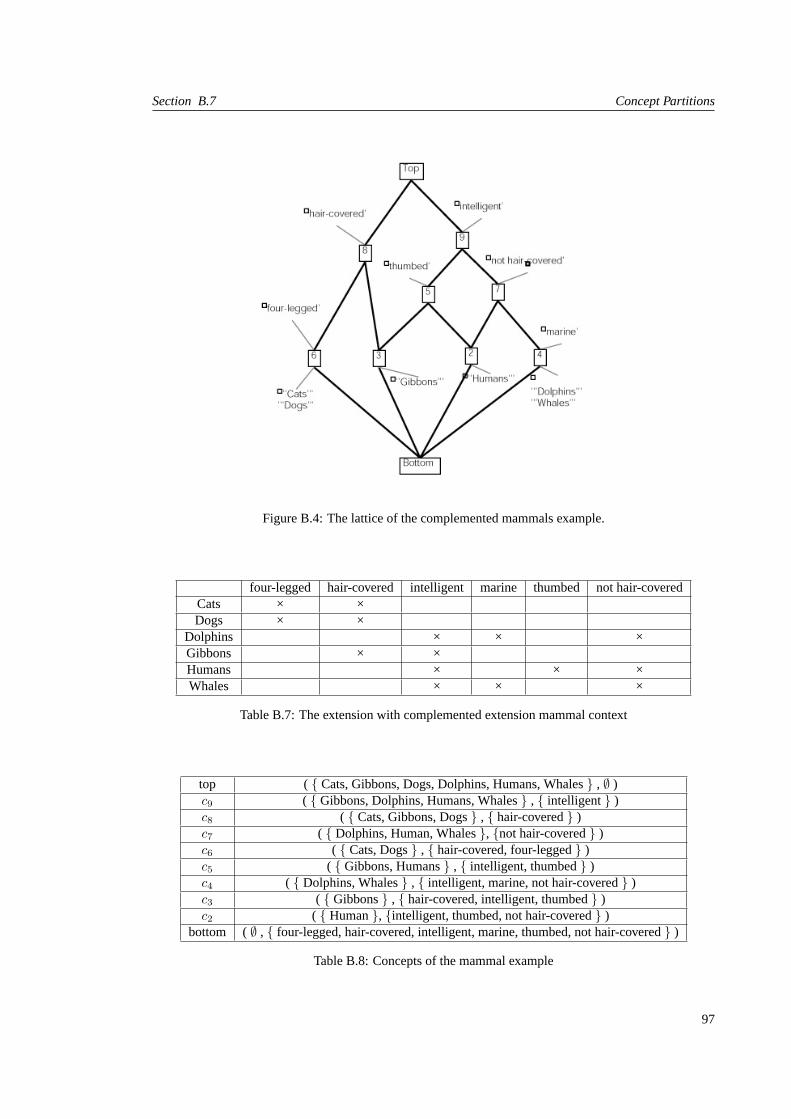
Section B.7 Concept Partitions
Figure B.4: The lattice of the complemented mammals example.
four-legged hair-covered intelligent marine thumbed not hair-coveredCats × ×Dogs × ×
Dolphins × × ×Gibbons × ×Humans × × ×Whales × × ×
Table B.7: The extension with complemented extension mammal context
top ( { Cats, Gibbons, Dogs, Dolphins, Humans, Whales} , ∅ )c9 ( { Gibbons, Dolphins, Humans, Whales} , { intelligent} )c8 ( { Cats, Gibbons, Dogs} , { hair-covered} )c7 ( { Dolphins, Human, Whales}, {not hair-covered} )c6 ( { Cats, Dogs} , { hair-covered, four-legged} )c5 ( { Gibbons, Humans} , { intelligent, thumbed} )c4 ( { Dolphins, Whales} , { intelligent, marine, not hair-covered} )c3 ( { Gibbons} , { hair-covered, intelligent, thumbed} )c2 ( { Human}, {intelligent, thumbed, not hair-covered} )
bottom ( ∅ , { four-legged, hair-covered, intelligent, marine, thumbed, not hair-covered} )
Table B.8: Concepts of the mammal example
97

Introduction to Formal Concept Analysis Appendix B
T1 {c2, c3, c4, c6}T2 {c2, c4, c8}T3 {c3, c6, c7}T4 { c4, c5, c6}T5 {c7, c8}T5 {top}
Table B.9: Concept partitions of the mammal concept extended with complemented properties
extended context to make in easier to distinguish elements. For example, ifσ{x} ( σ{y} then there is atleast one property which is a property ofy that is not a property ofx. Whether adding unique attributes orcomplementary attributes, negative information is represented in a positive form in the extended context tohelp distinguish suchx andy.
B.8 Finding Partitions in a Concept Lattice
We say that concept lattice derived from a well-formed context is a well-formed concept lattice. Oncethe context is well-formed, we are able to find the different partitions with the algorithm introduced inAlgorithm B.3.
Algorithm B.3: Algorithm to find the partitions of a well-formed concept lattice.(1) A← covs(⊥)(2) T ← {A}(3) W ← {A}(4) while W 6= ∅ do(5) remove somet from W(6) for each c ∈ t(7) for each c′ ∈ covers(c)(8) t′ ← t− subs(c′)(9) if (∪t′) ∩ c′ = ∅(10) t′′ ← t′ ∪ {c′}(11) if t′′ /∈ T(12) T ← T ∪ {t′′}(13) W ←W ∪ {t′′}(14) endif(15) endif(16) endfor(17) endfor(18) endwhile
The algorithm builds up a collection of all the partitions of a concept lattice. LetT the collection ofpartitions we are forming. LetW be a worklist of partitions. We begin with the atomic partitions, whichis thecoversof thebottomconcept of the concept lattice.T andW are both initialized to the singleton setcontaining the atomic partition.
The algorithm works by considering partitions from WorklistW until W is empty. For each partition re-moved fromW , new partitions are formed (when possible by selecting a concept of the partition, choosinga cover of that concept, adding it to the partition, and removing overlapping concepts.
As an example, consider the atomic partition of the concept lattice derived from the uniquely-attributedmammal context (B.3). The algorithm begins with the atomic partition (consisting of conceptc2, c3, c5 andc6) as the sole member of the worklist. The algorithm removes the atomic partition from the worklist, astin line (5). Suppose that in the first iteration of the for loop in line (6),c refers toc6. the covering set ofc6
98

Finding Partitions in a Concept Lattice
is the singleton set consisting ofc7, soc′ is assignedc7 in line (7). In line (8),t′ is assigned the value ofpminus the subordinate concepts ofc7 (i.e., c3, c6 andbottom, sot′ is {c2, c5}). In line (9), the union of theextents ofc2 andc5 is disjoint with the extent ofc7; thus, in line (10), the partitionp′′ = {c5, c2} ∪ {c7} isformed.p′′ is added to the set of partitions and to the worklist in line (12) and line (13).
In the worst case, the number of partitions can be exponential in the number of concepts. Furthermore,the techniques for making contexts well-formed, discussed so far, only exacerbate the problem: Moreprecise means of distinguishing sets of elements translates to more concepts. This is turns leads to morepossibilities for partitions.
If the number of concepts in a concept lattice is large, it may be impractical to consider every possiblepartitions of the concepts. In such a case, it is possible to adapt the algorithm to work interactively, withguidance from the user. Before attempting to find a new partition, the algorithm would pause for the userto specifyseed setsof concepts , which would be used to force the algorithm to find only coarser partitionsthan the seed sets (i.e., partitions that do not subdivide the seed sets).
99


Bibliography
[AACGJ01] Herve Albin-Amiot, Pierre Cointe, Yann-Gael Gueheneuc, and Narendra Jussien. Instantiat-ing and Detecting Design Patterns: Putting Bits and Pieces Together. In Debra Richardson,Martin Feather, and Michael Goedicke, editors,Proceedings of ASE ’01 (16th Conference onAutomated Software Engineering), pages 166–173. IEEE Computer Society Press, Novem-ber 2001.
[AB84] Mark S. Aldenderfer and Roger K. Blashfield.Cluster Analysis. Sage University PaperSeries on Quantitative Applications in the Social Sciences. Sage Publications Inc., BeverlyHills, 1984.
[ABN04] Gabriela Arevalo, Frank Buchli, and Oscar Nierstrasz. Detecting Implicit CollaborationPatterns. InProceedings of WCRE ’04 (11th Working Conference on Reverse Engineering),pages 122–131. IEEE Computer Society Press, November 2004.
[ADN03] Gabriela Arevalo, Stephane Ducasse, and Oscar Nierstrasz. X-Ray Views: Understandingthe Internals of Classes. InProceedings of ASE ’03 (18th Conference on Automated SoftwareEngineering), pages 267–270. IEEE Computer Society Press, October 2003. Short paper.
[Aeb03] Tobias Aebi. Extracting Architectural Information using Different Levels of Collaboration.Diploma Thesis, University of Bern, September 2003.
[AL97] Nicolas Anquetil and Timothy Lethbridge. File Clustering using Naming Conventions forLegacy Systems. InProceedings of CASCON ’97, pages 184–195, November 1997.
[AL99] Nicolas Anquetil and Timothy Lethbridge. Experiments with Clustering as a Software Re-modularization Method. InProceedings of WCRE ’99 (6th Working Conference on ReverseEngineering), pages 235–255, 150 Louis Pasteur, University of Ottawa, Ottawa, Canada,1999.
[And73] M. R. Andenberg.Cluster Analysis for Applications. Academic Press, London, 1973.
[Ar e03] Gabriela Arevalo. Understanding Behavioral Dependencies in Class Hierarchies using Con-cept Analysis. InProceedings of LMO ‘03 (Langages et Modelesa Objets), pages 47–59.Hermes, Paris, January 2003.
[AT01] Paul Anderson and Tim Teitelbaum. Software Inspection Using CodeSurfer. InProceedingsof WISE’01 (International Workshop on Inspection in Software Engineering), 2001.
[AYLCB96] Sihem Amer-Yahia, Lotfi Lakhal, Rosine Cicchetti, and Jean Paul Bordat. iO2 - An Algo-rithmic Method for Building Inheritance Graphs in Object Database Design. InProceedingsof ER’96 (15th International Conference on Conceptual Modeling), volume 1157 ofLectureNotes in Computer Science, pages 422–437. Springer-Verlag, 1996.
[Bal99] Thomas Ball. The Concept of Dynamic Analysis. InProceedings of ESEC/FSE ’99 (7thEuropean Software Engineering Conference and 7th ACM SIGSOFT International Sympo-sium on the Foundations of Software Engineering, number 1687 in LNCS, pages 216–234,sep 1999.
101

BIBLIOGRAPHY
[BDW98] Lionel C. Briand, John W. Daly, and Jurgen Wust. A Unified Framework for Cohesion Mea-surement in Object-Oriented Systems.Empirical Software Engineering: An InternationalJournal, 3(1):65–117, 1998.
[BE81] Laszlo. A. Belady and Carlo J. Evangelisti. System Partitioning and its Measure.Journal ofSystems and Software, 2:23–29, 1981.
[BH65] G. H. Ball and D. J. Hall. Isodata, A Novel Method of Data Analysis and Pattern Classifica-tion. Technical report, Stanford Research Institute, Menlo Park, California, 1965.
[Bir40] Garret Birkhoff. Lattice Theory.American Mathematical Society, 1940.
[BM70] M. Barbut and B. Monjardet.Ordre et Classification. Hachette, 1970.
[BMMM98] William J. Brown, Raphael C. Malveau, Hays W. McCormick, III, and Thomas J. Mowbray.AntiPatterns: Refactoring Software, Architectures, and Projects in Crisis. John Wiley Press,1998.
[BMR+96] Frank Buschmann, Regine Meunier, Hans Rohnert, Peter Sommerlad, and Michael Stad.Pattern-Oriented Software Architecture — A System of Patterns. John Wiley Press, 1996.
[Bro96] Kyle Brown. Design Reverse-Engineering and Automated Design Pattern Detection inSmalltalk. Masters Thesis, North Carolina State University, 1996.
[BS91] Rodrigo A. Botafogo and Ben Shneiderman. Identifying Aggregates in Hypertext Structures.In Proceedings CHI ’91 (Conference on Human Factors in Computing Systems), pages 63–74. ACM Press, 1991.
[BSR+01] Kathrin Bottger, Rolf Schwitter, Debbie Richards, Oscar Aguilera, and Diego Molla. Rec-onciling Use Cases via Controlled Language and Graphical Models. InProceedings of INAP’01 (14th International Conference on Applications of Prolog), pages 20–22, Japan, October2001. University of Tokyo.
[Buc02] Frank Buchli. An explicit model for ADVance. Informatikprojekt, University of Bern, De-cember 2002.
[Buc03] Frank Buchli. Detecting Software Patterns using Formal Concept Analysis. Diploma thesis,University of Bern, September 2003.
[Bud91] Timothy A. Budd.An Introduction to Object-Oriented Programming. Addison Wesley, 1991.
[BV00] Dragan Bojic and Dusan Velasevic. Reverse Engineering of Use Case Realizations in UML.In Proceedings of SAC ’00 (ACM Symposium on Applied Computing). ACM Press, 2000.
[CC92] Elliot J. Chikofsky and James H. Cross, II. Reverse Engineering and Design Recovery:A Taxonomy. In Robert S. Arnold, editor,Software Reengineering, pages 54–58. IEEEComputer Society Press, 1992.
[CCLL99] Gerardo Canfora, Aniello Cimitile, Andrea De Lucia, and Giuseppe A. Di Lucca. A CaseStudy of Applying an Eclectic Approach to Identify Objects in Code. InProceedings ofIWPC ’99 (7th International Workshop on Program Comprehension), pages 136–143. IEEE,IEEE Computer Society, May 1999.
[CIMH98] James H. Cross II, Saeed Maghsoodloo, and Dean Hendrix. Control Structure Diagrams:Overview and Evaluation.Journal of Empirical Software Engineering, 3(2):131–158, 1998.
[CL96] Jan-Bon Chen and Samuel C. Lee. Generation and Reorganization of Subtype hierarchies.Journal of Object Oriented Programming, 8(8):26–35, January 1996.
102

BIBLIOGRAPHY
[CLR90] Thomas H. Corman, Charles E. Leiserson, and Ronald L. Rivest.Introduction to Algorithms.MIT Press, 1990.
[Coo92] William R. Cook. Interfaces and Specifications for the Smalltalk-80 Collection Classes. InProceedings of OOPSLA ’92 (7th Conference on Object-Oriented Programming Systems,Languages and Applications), volume 27, pages 1 – 15. ACM Press, October 1992.
[CS90] Song C. Choi and Walt Scacchi. Extracting and Restructuring the Design of Large Systems.IEEE Software, pages 66–71, January 1990.
[DDHL95] Herve Dicky, Christoph Dony, Marianne Huchard, and Therese Libourel. ARES, Addinga class and REStructuring Inhertitance Hierarchy. InBDA : 11emes Journees Bases deDonnees Avancees, pages 25–42, 1995.
[DDHL96] Herve Dicky, Christoph Dony, Marianne Huchard, and Therese Libourel. On AutomaticClass Insertion with Overloading. InProceedings of OOPSLA ’96 (11th ACM SIGPLANconference on Object-oriented Programming, Systems, Languages, and Applications), pages251–267. ACM Press, 1996.
[DDN02] Serge Demeyer, Stephane Ducasse, and Oscar Nierstrasz.Object-Oriented ReengineeringPatterns. Morgan Kaufmann, 2002.
[Dek03] Uri Dekel. Revealing JAVA Class Structures using Concept Lattices. Diploma thesis,Technion-Israel Institute of Technology, February 2003.
[DGLD04] Stephane Ducasse, Tudor Gırba, Michele Lanza, and Serge Demeyer. Moose: a Collabora-tive and Extensible Reengineering Environment. InReengineering Environments. 2004. toappear.
[DH98] Stephan Duwel and Wolfgang Hesse. Identifying Candidate Objects during System Anal-ysis. In Proceedings of CAiSE’98/IFIP 8.1 3rd International Workshop on Evaluation ofModelling Methods in System Analysis and Design (EMMSAD’98), Pisa, 1998.
[DH00] Stephan Duwel and Wolfgang Hesse. Bridging the Gap between Use Case Analysis andClass Structure Design by Formal Concept Analysis. In J. Ebert and U. Frank, editors,Modelle und Modellierungssprachen in Informatik und Wirtschaftsinformatik. Proceedings“Modellierung 2000”, pages 27–40, Koblenz, 2000. Folbach-Verlag.
[DHHaV04] Michel Dao, Marianne Huchard, Mohamed Rouane Hacene, and Cyril Roume andPetkoValtchev. Improving Generalization Level in UML Models Iterative Cross Generalization inPractice. InProceedings of ICCS ’94 (12th International Conference on Conceptual Struc-tures), volume 3127 ofLecture Notes in Computer Science, pages 346–360. Springer-Verlag,July 2004.
[DHL+02] Michel Dao, Marianne Huchard, Therese Libourel, Cyril Roume, and Herve Leblanc. A NewApproach to Factorization: Introducing Metrics. InProceedings of METRICS ’02 (8th IEEEInternational Symposium on Software Metrics, pages 227 – 236. IEEE Computer Society,2002.
[DP02] B.A. Davey and H. A. Priestley.Introduction to Lattices and Order: Second Edition. Cam-bridge University Press, 2002.
[DRW00] Alastair Dunsmore, Marc Roper, and Murray Wood. Object-Oriented Inspection in the Faceof Delocalisation. InProceedings of ICSE ’00 (22nd International Conference on SoftwareEngineering), pages 467–476. ACM Press, 2000.
[Duw99] Stephan Duwel. Enhancing System Analysis by Means of Formal Concept Analysis. InConference on Advanced Information Systems Engineering. 6th Doctoral Consortium, Hei-delberg, Germany, June 1999.
103

BIBLIOGRAPHY
[EKS01a] Thomas Eisenbarth, Rainer Koschke, and Daniel Simon. Aiding Program Comprehension byStatic and Dynamic Feature Analysis. InProceedings of ICSM ’01 (International Conferenceon Software Maintenance). IEEE Computer Society Press, 2001.
[EKS01b] Thomas Eisenbarth, Rainer Koschke, and Daniel Simon. Feature-Driven Program Under-standing using Concept Analysis of Execution Traces. InProceedings of IWPC ’01 (9thInternational Workshop on Program Comprehension), pages 300–309. IEEE Computer So-ciety Press, 2001.
[EKS03] Thomas Eisenbarth, Rainer Koschke, and Daniel Simon. Locating Features in Source Code.IEEE Computer, 29(3):210–224, March 2003.
[Eve74] B. Everitt.Cluster Analysis. Heineman Educational Books, London, 1974.
[FBB+99] Martin Fowler, Kent Beck, John Brant, William Opdyke, and Don Roberts.Refactoring:Improving the Design of Existing Code. Addison Wesley, 1999.
[Fis98] Bernd Fischer. Specification-based Browsing of Software Component Libraries. InProceed-ings of ASE ’98(13th Conference on Automated Software Engineering, pages 74–83. IEEEComputer Society Press, 1998.
[FLS95] Petra Funk, Anke Lewien, and Gregor Snelting. Algorithms for Concept Lattice Decompo-sition and their Application. Technical Report 95-09, Computer Science Dept., TechnischeUniversitat Braunschweig, 1995.
[FP96] Norman Fenton and Shari Lawrence Pfleeger.Software Metrics: A Rigorous and PracticalApproach. International Thomson Computer Press, London, UK, second edition, 1996.
[Fur86] George W. Furnas. Generalized Fisheye View. InProceedings of CHI ’86 (Conference onHuman Factors in Computing Systems), pages 16–23. ACM Press, 1986.
[GDL04] Tudor Gırba, Stephane Ducasse, and Michele Lanza. Yesterday’s Weather: Guiding EarlyReverse Engineering Efforts by Summarizing the Evolution of Changes. InProceedings ofICSM ’04 (International Conference on Software Maintenance), pages 40–49. IEEE Com-puter Society Press, 2004.
[GHJV95] Erich Gamma, Richard Helm, Ralph Johnson, and John Vlissides.Design Patterns: Elementsof Reusable Object-Oriented Software. Addison Wesley, Reading, Mass., 1995.
[GHRV02] Robert Godin, Marianne Huchard, Cyrill Roume, and Petko Valtchev. Inheritance and Au-tomation: Where Are We Now? In Andrew Black, Erik Ernst, Peter Grogono, and MarkkySakkinen, editors,ECOOP 2002: Proceedings of the Inheritance Workshop, pages 58–64.University of Jyvaskyla, June 2002.
[GL70] I. Gitman and M. D. Levine. An Algorithm for Detecting Unimodal Fuzzy Sets and ItsApplication as a Clustering Technique.IEEE Transactions on Computers, CE-19:583–593,July 1970.
[GL91] Keith Brian Gallagher and James R. Lyle. Using Program Slicing in Software Maintenance.Transactions on Software Engineering, 17(18):751–761, August 1991.
[GM93] Robert Godin and Hafedh Mili. Building and Maintaining Analysis-Level Class Hierarchiesusing Galois Lattices. InProceedings OOPSLA ’93 (8th Conference on Object-OrientedProgramming Systems, Languages, and Applications), volume 28, pages 394–410, October1993.
[GMM+95] Robert Godin, Guy Mineau, Rokia Missaoui, Marc St-Germain, and Najib Faraj. Apply-ing Concept Formation Methods to Software Reuse.International Journal of KnowledgeEngineering and Software Engineering, 5(1):119–142, 1995.
104

BIBLIOGRAPHY
[GMM+98] Robert Godin, Hafedh Mili, Guy W. Mineau, Rokia Missaoui, Amina Arfi, and Thuy-TienChau. Design of Class Hierarchies based on Concept (Galois) Lattices.Theory and Appli-cation of Object Systems, 4(2):117–134, 1998.
[Gor81] A. D. Gordon.Classification: Methods for the Exploratory Analysis of Multivariate Data.Chapman & Hall Ltd., London, 1981.
[GW99] Bernhard Ganter and Rudolf Wille.Formal Concept Analysis: Mathematical Foundations.Springer Verlag, 1999.
[HB85] David H. Hutchens and Victor R. Basili. System Structure Analysis: Clustering with DataBindings. IEEE Transactions on Software Engineering, 11(8):749–757, August 1985.
[HCIM02] Dean Hendrix, James H. Cross II, and Saeed Maghsoodloo. The Effectiveness of ControlStructure Diagrams in Source Code Comprehension Activities.IEEE Transactions on Soft-ware Engineering, 28(5):463–477, May 2002.
[HDL00] Marianne Huchard, Herve Dicky, and Herve Leblanc. Galois Lattice as a Framework tospecify Algorithms Building Class Hierarchies.Theoretical Informatics and Applications,34:521–548, 2000.
[HK00] Jiawei Han and Micheline Kamber.Data Mining: Concept and Techniques. Morgan Kauf-mann, 2000.
[IC 01] IC & C GmBH Software Foundations, Papenhoehe 14, D-25335 Elmshorn/Hamburg, Ger-many.ADvance User’s Guide, August 2001.
[JD88] Anil K. Jain and Richard C. Dubes.Algorithms for Clustering Data. Prentice Hall, Engle-wood Cliffs, 1988.
[JGR99] Mehdi Jazayeri, Harald Gall, and Claudio Riva. Visualizing Software Release Histories: TheUse of Color and Third Dimension. InProceedings of ICSM ’99 (International Conferenceon Software Maintenance), pages 99–108. IEEE Computer Society Press, 1999.
[JR97] Dean Jerding and Spencer Rugaber. Using Visualization for Architectural Localization andExtraction. In Ira Baxter, Alex Quilici, and Chris Verhoef, editors,Proceedings of WCRE ’97(4th Working Conference on Reverse Engineering), pages 56 – 65. IEEE Computer SocietyPress, 1997.
[KG88] Michael F. Kleyn and Paul C. Gingrich. GraphTrace – Understanding Object-Oriented Sys-tems using Concurrently Animated Views. InProceedings OOPSLA ’88 (InternationalConference on Object-Oriented Programming Systems, Languages, and Applications, vol-ume 23, pages 191–205. ACM Press, November 1988.
[KM00] Tobias Kuipers and Leon Moonen. Types and Concept Analysis for Legacy Systems. Tech-nical Report SEN-R0017, Centrum voor Wiskunde en Informatica, July 2000.
[KO01] Sergei Kuznetsov and Sergei Obedkov. Comparing Performance of Algorithms for Generat-ing Concept Lattices. InProceedings of International Workshop on Concept Lattice-basedTheory, Methods and Tools for Knowledge Discovery in Databases, 2001.
[Kos00] Rainer Koschke.Atomic Architectural Component Recovery for Program Understandingand Evolution. PhD thesis, Universitat Stuttgart, 2000.
[KP96] Christian Kramer and Lutz Prechelt. Design Recovery by Automated Search for StructuralDesign Patterns in Object-Oriented Software. InProceedings of WCRE ’96 (3rd Work-ing Conference on Reverse Engineering), pages 208–216. IEEE Computer Society Press,November 1996.
105

BIBLIOGRAPHY
[KR90] L. Kaufman and P. J. Rousseeuw.Finding Groups in Data: An Introduction to ClusterAnalysis. Wiley Series in Probability and Mathematical Statistics. John Wiley & Sons Inc.,New York, 1990.
[KS94] Maren Krone and Gregor Snelting. On the Inference of Configuration Structures from SourceCode. InProceedings of ICSE ’94 (16th International Conference on Software Engineering),pages 49–57. IEEE Computer Society / ACM Press, 1994.
[KSRP99] Rudolf K. Keller, Reinhard Schauer, Sebastien Robitaille, and Patrick Page. Pattern-BasedReverse Engineering of Design Components. InProceedings of ICSE ’99 (21st InternationalConference on Software Engineering), pages 226–235. IEEE Computer Society Press / ACMPress, May 1999.
[KST96] Edward J. Klimas, Suzanne Skublics, and David A. Thomas.Smalltalk with Style. Prentice-Hall, 1996.
[Lan99] Michele Lanza. Combining Metrics and Graphs for Object Oriented Reverse Engineering.Diploma Thesis, University of Bern, October 1999.
[Lan03] Michele Lanza.Object-Oriented Reverse Engineering — Coarse-grained, Fine-grained, andEvolutionary Software Visualization. PhD thesis, University of Berne, May 2003.
[LB85] Manny M. Lehman and Les Belady.Program Evolution – Processes of Software Change.London Academic Press, 1985.
[LD01] Michele Lanza and Stephane Ducasse. A Categorization of Classes based on the Visualiza-tion of their Internal Structure: the Class Blueprint. InProceedings of OOPSLA ’01 (Interna-tional Conference on Object-Oriented Programming Systems, Languages and Applications),pages 300–311. ACM Press, 2001.
[Leb00] Herve Leblanc.Sous-hierarchies de Galois: un Modele pour la Construction et L’evolutiondes Hierarchies d’objets (Galois Sub-hierarchies: a Model for Construction and Evolutionof Object Hierarchies). PhD thesis, Universite Montpellier 2, 2000.
[Lin95] Christian Lindig. Concept-Based Component Retrieval. In J. Kohler, F. Giunchiglia,C. Green, and C. Walther, editors,Working Notes of the IJCAI-95 Workshop: Formal Ap-proaches to the Reuse of Plans, Proofs, and Programs, pages 21–25, August 1995.
[LN95] Danny B. Lange and Yuichi Nakamura. Interactive Visualization of Design Patterns can helpin Framework Understanding. InProceedings of OOPSLA ’95 (International Conferenceon Object-Oriented Programming Systems, Languages and Applications), pages 342–357.ACM Press, 1995.
[LPLS96] David Littman, Jeannine Pinto, Stan Letovsky, and Elliot Soloway. Mental Models andSoftware Maintenance. In Soloway and Iyengar, editors,Empirical Studies of Programmers,First Workshop, pages 80–98. Ablex Publishing Corporation, 1996.
[LRP95] John Lamping, Ramana Rao, and Peter Pirolli. A Focus + Context Technique based onHyperbolic Geometry for Visualising Large Hierarchies. InProceedings of CHI ’95 (Inter-national Conference on Human Factors in Computing Systems). ACM Press, 1995.
[Lun98] Chung-Horng Lung. Software Architecture Recovery and Restructuring through ClusteringTechniques. InProceedings of the 3rd International Workshop on Software Architecture,pages 101–104. ACM Press, 1998.
[LY97] Tim Lindholm and Frank Yellin.The Java Virtual Machine Specification. Addison Wesley,1997.
106
BIBLIOGRAPHY
[Mac67] J. B. MacQueen. Some Methods for Classification and Analysis of Multivariate Observa-tions. In Proceedings of the 5th Symposium on Mathematics, Statistics and Probability,pages 281–297, Berkley, 1967. University of California Press.
[MH00] Richard Monson-Haefel.Enterprise JavaBeans. O’Reilly & Associates, Inc., 2nd edition,2000.
[MM98] Spiros Mancoridis and Brian S. Mitchell. Using Automatic Clustering to produce High-LevelSystem Organizations of Source Code. InProceedings of IWPC ’98 (International Workshopon Program Comprehension). IEEE Computer Society Press, 1998.
[MM01] Brian S. Mitchell and Spiros Mancoridis. Comparing the Decompositions Produced bySoftware Clustering Algorithms using Similarity Measurements. InProceedings of ICSM’01 (International Conference on Software Maintenance). IEEE Computer Society Press,November 2001.
[MMCG99] Spiros Mancoridis, Brian S. Mitchell, Y. Chen, and E. R. Gansner. Bunch: A ClusteringTool for the Recovery and Maintenance of Software System Structures. InProceedingsof ICSM ’99 (International Conference on Software Maintenance), Oxford, England, 1999.IEEE Computer Society Press.
[Moo96] Ivan Moore. Automatic Inheritance Hierarchy Restructuring and Method Refactoring. InProceedings of OOPSLA ’96 (11th Annual Conference on Object-Oriented ProgrammingSystems, Languages, and Applications), pages 235–250. ACM Press, 1996.
[MS89] Michele Missikoff and Michel Scholl. An algorithm for insertion into a lattice: Applicationto type classification. InProceedings of FODO ’89 (3rd International Conference on Foun-dations of Data Organization and Algorithms, volume 367 ofLecture Notes in ComputerScience, pages 64–82. Springer-Verlag, June 1989.
[MS95] Alberto Mendelzon and Johannes Sametinger. Reverse engineering by visualizing and query-ing. Software — Concepts and Tools, 16:170–182, 1995.
[MS98] Leonid Mikhajlov and Emil Sekerinski. A Study of the Fragile Base Class Problem. InPro-ceedings of ECOOP’98 (European Conference on Object-Oriented Programming), number1445 in Lecture Notes in Computer Science, pages 355–383. Springer-Verlag, 1998.
[MU90] Hausi A. Muller and James S. Uhl. Composing Subsystem Structures using (k,2)-partitegraphs. InProceedings of ICSM ’90 (International Conference on Software Maintenance),pages 12–19. IEEE Computer Society Press, November 1990.
[Mul86] Hausi A. Muller. Rigi — A Model for Software System Construction, Integration, and Eval-uation based on Module Interface Specifications. PhD thesis, Rice University, 1986.
[Mul93] Hausi A. Muller. Software Engineering Education should concentrate on Software Evolution.In Proceedings of National Workshop on Software Engineering Education, pages 102 – 104,May 1993. University of Victoria (Canada).
[Nei96] James M. Neighbors. Finding Reusable Software Components in Large Systems. InPro-ceedings of WCRE ’96 (3rd Working Conference on Reverse Engineering), pages 2–10. IEEEComputer Society Press, November 1996.
[NR89] Jakob Nielsen and John T. Richards. The Experience of Learning and Using Smalltalk.IEEESoftware, 6(3):73–77, 1989.
[NSW+02] Jorg Niere, Wilhelm Schafer, Jurg P. Wadsack, Lothar Wendehals, and Jim Welsh. Towardspattern-based design recovery. InProceedings of ICSE ’02 (24th International Conferenceon Software Engineering), pages 338–348. ACM Press, 2002.
107

BIBLIOGRAPHY
[OMG99] Object Management Group. Unified Modeling Language (version 1.3). Technical report,Object Management Group, June 1999.
[Par94] David Lorge Parnas. Software Aging. InProceedings of ICSE ’94 (International Conferenceon Software Engineering), pages 279–287. IEEE Computer Society / ACM Press, 1994.
[RB02a] Debbie Richards and Kathrin Bottger. Assisting Decision Making in Requirements Reconcil-iation. InProceedings of CSCWD ’02 (7th International Conference on Computer SupportedCooperative Work in Design), Brazil, September 2002. IEEE Computer Society Press.
[RB02b] Debbie Richards and Kathrin Bottger. A Controlled Language to Assist Conversion of UseCase Descriptions into Concept Lattices. InProceedings of AI ’02 (15th Australian JointConference on Artificial Intelligence), number 2557 in LNAI, pages 579 – 590, Canberra,Australia, 2002. Springer Verlag.
[RB02c] Debbie Richards and Kathrin Bottger. Representing Requirements in Natural Language asConcept Lattices. InProceedings of the 22nd Annual International Conference of the BritishComputer Society’s Specialist Group on Artificial Intelligence (ES2002), Cambridge, De-cember 2002. Springer Verlag.
[RBF02a] Debbie Richards, Kathrin Bottger, and Anne Fure. RECOCASE-tool: A CASE Tool forRECOnciling Requirements Viewpoints. InProceedings of AWRE ’02 (7th Australian Work-shop on Requirements Engineering), 2002.
[RBF02b] Debbie Richards, Kathrin Bottger, and Anne Fure. Using RECOCASE to compare use casesfrom multiple viewpoints. InProceedings of ACIS ’02 (13th Australasian Conference onInformation Systems), Melbourne, Australia, December 2002.
[RHM00] Peter Rosner, Tracy Hall, and Tobias Mayer. Measuring Object-Orientedness: The Invo-cation Profile. In Reiner R. Dumke and Alain Abran, editors,Proceedings of IWSM ’00(10th International Workshop on New Approaches in Software Measurement), pages 18–28.Springer-Verlag, October 2000.
[Ric02] Tamar Richner.Recovering Behavioral Design Views: a Query-Based Approach. PhD thesis,University of Berne, May 2002.
[Riv96] Fred Rivard. Smalltalk : a Reflective Language. InProceedings of REFLECTION ’96, pages21–38, April 1996.
[Rog71] J. H. Roger. Updating a minimum spanning tree. algorithm as40.Applied Statistics, 20:204–206, 1971.
[Ros69] G. J. S. Ross. Minimum spanning tree. algorithm as13.Applied Statistics, 18:103–104, 1969.
[Rou02] Cyrill Roume. Evaluation Structurelle de la Factorisation et la Generalisation au sein desHierarchies de Classes: Introduction de Metriques.L’Objet, 8(1-2):151–166, 2002.
[Run92] Elke A. Rundensteiner. A Class Classification Algorithm for Supporting Consistent ObjectViews. Technical report, University of Michigan, 1992.
[SAP89] Robert W. Schwanke, Rita Z. Altucher, and Michael A. Platoff. Discovering, Visualizing,and Controlling Software Structure. InProceedings of International Workshop on SoftwareSpecification and Design, pages 147–150. IEEE Computer Society Press, 1989.
[Sch91] Robert W. Schwanke. An intelligent tool for re-engineering software modularity. InPro-ceedings of the 13th International Conference on Software Engineering, pages 83–92, May1991.
108

BIBLIOGRAPHY
[SFM99] Margaret-Anne D. Storey, F. David Fracchia, and Hausi A. Muller. Cognitive Design Ele-ments to Support the Construction of a Mental Model during Software Exploration.Journalof Software Systems, 44:171–185, 1999.
[Sha96] Subhash Sharma.Applied Multivariate Techniques. John Wiley, 1996.
[SLL+88] Elliot Soloway, Robin Lampert, Stan Letovsky, David Littman, and Jeannine Pinto. De-signing Documentation to Compensate for Delocalized Plans.Commununications of ACM,31(11):1259–1267, 1988.
[SLMD96] Patrick Steyaert, Carine Lucas, Kim Mens, and Theo D’Hondt. Reuse Contracts: Managingthe Evolution of Reusable Assets. InProceedings of OOPSLA ’96 (International Conferenceon Object-Oriented Programming, Systems, Languages, and Applications), pages 268–285.ACM Press, 1996.
[SM95] Margaret-Anne D. Storey and Hausi A. Muller. Manipulating and Documenting SoftwareStructures using SHriMP Views. InProceedings of ICSM ’95 (International Conference onSoftware Maintenance), pages 275 – 284. IEEE Computer Society Press, 1995.
[SMLD97] Houari A. Sahraoui, Walcelio Melo, Hakim Lounis, and Francois Dumont. Applying Con-cept Formation Methods to Object Identification in Procedural Code. InProceedings of ASE’97 (12th International Conference on Automated Software Engineering), pages 210–218.IEEE, IEEE Computer Society Press, November 1997.
[SMSP04] Sreedevi Sampath, Valentin Mihaylov, Amie Souter, and Lori Pollock. A Scalable Approachto User-Session based Testing of Web Applications through Concept Analysis. InProceed-ings of ASE ’04 (19th International Conference on Automated Software Engineering), pages132–141. IEEE Computer Society Press, September 2004.
[Sne96] Gregor Snelting. Reengineering of Configurations Based on Mathematical Concept Analysis.ACM Transactions on Software Engineering and Methodology, 5(2):146–189, April 1996.
[Sne98] Gregor Snelting. Concept Analysis – a New Framework for Program Understanding. InSIGPLAN/SIGSOFT Workshop on Program Analysis for Software Tools and Engineering(PASTE), pages 1–10, Montreal, Canada, June 1998. ACM Press.
[SP89] Robert W. Schwanke and Michael A. Platoff. Cross References are Features. InProceedingsof Second International Workshop on Software Configuration Management, pages 86–95.ACM Press, 1989.
[Spi89] J. Spivey.The Z Notation: A Reference Manual. Prentice-Hall, 1989.
[SR97] Michael Siff and Thomas Reps. Identifying Modules via Concept Analysis. InProceedingsof ICSM ’97 (International Conference on Software Maintenance), pages 170–179. IEEEComputer Society Press, 1997.
[SRMK99] Reinhard Schauer, Sebastian Robitaille, Francois Martel, and Rudolf Keller. Hot-Spot Re-covery in Object-Oriented Software with Inheritance and Composition Template Methods.In Proceedings of ICSM ’99 (International Conference on Software Maintenance). IEEEComputer Society Press, 1999.
[SS73] P.H.A. Sneath and R.R. Sokal.Numerical Taxonomy: The Principles and Practice of Nu-merical Classification. W. H. Freeman and Company, San Francisco, 1973.
[ST97] Gregor Snelting and Frank Tip. Reengineering Class Hierarchies using Concept Analysis.Technical Report RC 21164(94592)24APR97, IBM T.J. Watson Research Center, IBM T.J.Watson Research Center, P.O. Box 704, Yorktown Heights, NY 10598, USA, 1997.
109

BIBLIOGRAPHY
[ST98] Gregor Snelting and Frank Tip. Reengineering Class Hierarchies using Concept Analysis.In ACM Trans. Programming Languages and Systems, 1998.
[Ste92] Robert A. Stegwee.Division for Conquest - Decision Support for Information ArchitectureSpecification. Ph.D. thesis, University of Groningen, Groningen, The Netherlands, 1992.
[SvG98] Jochen Seemann and Jurgen Wolff von Gudenberg. Pattern-Based Design Recovery of JAVASoftware. InProceedings of the 6th ACM SIGSOFT International Symposium on Founda-tions of Software Engineering, pages 10–16. ACM Press, 1998.
[TA99] Paolo Tonella and Giuliano Antoniol. Object Oriented Design Pattern Inference. InPro-ceedings of ICSM ’99 (International Conference on Software Maintenance), pages 230–238.IEEE Computer Society Press, October 1999.
[TC04] Paolo Tonella and Mariano Ceccato. Aspect Mining through the Formal Concept Analysis ofExecution Traces. InProceedings of WCRE 2004 (11th International Working Conferencein Reverse Engineering), pages 112–121. IEEE Computer Society Press, November 2004.
[TCBE03] Thomas Tilley, Richard Cole, Peter Becker, and Peter Eklund. A Survey of Formal ConceptAnalysis Support for Software Engineering Activities. In Gerd Stumme, editor,Proceedingsof ICFCA ’03 (1st International Conference on Formal Concept Analysis). Springer-Verlag,February 2003.
[TDDN00] Sander Tichelaar, Stephane Ducasse, Serge Demeyer, and Oscar Nierstrasz. A Meta-modelfor Language-Independent Refactoring. InProceedings of ISPSE ’00 (International Confer-ence on Software Evolution), pages 157–167. IEEE Computer Society Press, 2000.
[TH98] Vassilios Tzerpos and R. C. Holt. Software Botryology, Automatic Clustering of SoftwareSystems. InProceedings of the 9th International Workshop on Database and Expert SystemsApplications. IEEE Computer Society Press, 1998.
[Tic01] Sander Tichelaar.Modeling Object-Oriented Software for Reverse Engineering and Refac-toring. PhD thesis, University of Berne, December 2001.
[Til03] Thomas Tilley. Towards an FCA Based Tool for Visualising Formal Specifications. InB. Ganter and A. de Moor, editors,Using Conceptual Structures: Contributions to ICCS2003, pages 227–240. Shaker Verlag, 2003.
[Ton01] Paolo Tonella. Concept Analysis for Module Restructuring.IEEE Transactions on SoftwareEngineering, 27(4):351–363, April 2001.
[vDK99] Arie van Deursen and Tobias Kuipers. Identifying Objects using Cluster and Concept Anal-ysis. InProceedings of ICSE ’99 (21st International Conference on Software Engineering),pages 246–255. ACM Press, 1999.
[Vis03] Cincom Smalltalk, September 2003. http://www.cincom.com/scripts/smalltalk.dll/.
[vL93] Gregor von Laszewski. A Collection of Graph Partitioning Algorithms: Simulated Anneal-ing, Simulated Tempering, Kernighan Lin, Two Optimal, Graph Reduction, Bisection. Tech-nical Report SCCS 477, Northeast Parallel Architectures Center, Syracuse University, Syra-cuse, New York, 1993.
[vR79] C. v. Rijsbergen.Information Retrieval. Butterworths, London, 1979.
[WBWW90] Rebecca Wirfs-Brock, Brian Wilkerson, and Lauren Wiener.Designing Object-OrientedSoftware. Prentice-Hall, 1990.
[WH92] Norman Wilde and Ross Huitt. Maintenance Support for Object-Oriented Programs.IEEETransactions on Software Engineering, SE-18(12):1038–1044, December 1992.
110

BIBLIOGRAPHY
[Wig97] Theo Wiggerts. Using Clustering Algorithms in Legacy Systems Remodularization. In IraBaxter, Alex Quilici, and Chris Verhoef, editors,Proceedings of WCRE ’97 (4th WorkingConference on Reverse Engineering), pages 33 – 43. IEEE Computer Society Press, 1997.
[Wil81] Rudolf Wille. Restructuring Lattice Theory: An Approach Based on Hierarchies of Con-cepts.Ordered Sets, Ivan Rival Ed., NATO Advanced Study Institute, 83:445–470, September1981.
[Wis69] David Wishart. Mode Analysis: A Generalization of Nearest Neighbour which reduceschaining effects.Numerical Taxonomy, 1969.
[XLZS04] Xia Xu, Chung-Horng Lung, Maria Zaman, and Anand Srinivasan. Program Restructurethrough Clustering Technique. InProceedings of International Workshop on Source CodeAnalysis and Manipulation, pages 75 – 84. IEEE, IEEE Computer Society Press, September2004.
111


Curriculum Vitae
Personal Information
Name: Gabriela Beatriz ArevaloNationality: ArgentinianDate of Birth: September 14th, 1973Place of Birth: San Salvador de Jujuy, Argentina
Education
Sept. 2000 - Jan. 2005: Ph.D. in Computer Science in the Software Composition Group, University ofBern, SwitzerlandSubject of the Ph.D. thesis:“High-Level Views in Object-Oriented Systems using Formal Concept Analysis”
Sept. 1999 - Aug. 2000: Master of Science in Computer Science in the context of EMOOSE (EuropeanMaster in Object-Oriented Software Engineering) program in Ecole des Mines deNantes, France.Subject of the Master thesis:“Object-Oriented Architectural Description of Frameworks”Degree awarded by Faculteit Van de Wetenschappen, Vrije Universiteit Brussel,Belgium
1992 - Mar. 1999: Licenciatura en Informatica in Facultad de Ciencias Exactas in Universidad Na-cional de La Plata, Buenos Aires, ArgentinaSubject of Licenciatura thesis:“G.I.S + Oceans = A strange combination”(in Spanish)
1987 - 1991: Secondary School in Buenos Aires, Argentina1979 - 1986: Primary School in Buenos Aires, Argentina
113
