high-fidelity techniques - world radio history
TRANSCRIPT

High-Fidelity
Techniques By JAMES R. LANGHAM
•

HIGH-FIDELITY
TECHNIQUES
by
JAMES R. LANGHAM
Gernsback Library No. 42
PUBLISHED BY
RADCRAFT PUBLICATIONS, INC.
25 West Broadway,
New York 7, N. Y.

COPYRIGHT, 1950
BY HUGO GERNSBACK
All Rights Reserved
First Printing-July 1950
Second Printing-November 1950
Third Printing-April 1952

High-Fidelity Techniques
ABOUT THIS BOOK , ... , , . , , .. , , , , , , , , , , , , , , , , , , , , .. , , , , , , , , , , , , , , , , , , • , , , , , 5 CHAPTER 1, , , DISTORTIOX , • , , , , , , , , , , , , , , , , , , , , , , , , .. , , . , . , , •• , , , , , , , , , , , , , 7
Percentage of distortion. Speaker distortion. Transient distortion. Pickup, record, and stylus distortion. Amplifier distortion. Power output versus percentage of distortion. Distortion in output stage, Harmonics. Second harmonic distortion. Third harmonic distortion. Transformer distortion. Overloading. Square wave generator. Transients. Testing with square waves. Intermodulation. Improving linearity. Phase distortion.
CHAPTER 2 ... SPEAKERS AND BAFFLES ..... , .. ,. •• , • , ............. , , ...... , , • 15 Speaker impedance. Acoustic impedance. Tuned boxes. Flat baffles. Helmholtz resonator. Speaker resonance. Infinite haffie. Rox resonance. Tuned box design. Box padding. Labyrinth. Frequency versus wavelength. l1inimizing speaker resonance. Multispeaker installa-tions. Dual systems. Divided presence. Horns. Horn design. Cross-over networks. Constant-impedance network. M-derived network. Crossover network design. Bass horns. Phasing. Folded horns. Speaker phasing.
CHAPTER 3, , , POWER AMPLIFIERS , , , , • , , • , , , , , • , , , , , , , • , , , , , , , , . , • , , , , , , , , , , 35 Power output. Power output requirements. Output transformers. Testing transformers. Transformer bass response. Transformer primary inductance and leakage reactance. Equivalent transformer circuit. Output tubes. Low-mu triodes. Maximum power transfer. Speaker damping. Beam power tubes. Cathode loading. Beam tube amplifier. Class A. Class AB. Phase inversion. Standard phase inverter. Floating inverter. Split load inverter. Cathode coupled inverter. Push-pull crystal pickup. Self bias. Fixed bias. Back bias. Amplifier fusing. Direct-coupled amplifier.
CHAPTER 4., ,AMPLIFIER DESIGN , • , , • , , • , , , , , , , , , , •.....•..•...•. , , , , , , , , • , , SJ Inverse feedback. Feedback loop. Percentage feedback. Calculating feedback. Gain reduction factor, Positive feedback. Voltage feedback. Current feedback. Balancing output tubes. Variable bias. Variable drive. Variable bias and drive. Plate resistance. Transconductance, Amplification factor. Plate load resistance. Load line. Tube distortion. Cathode bypass. Volume expansion. AB-triode amplifier. Cathode follower. Contact bias. Frequency limits. Time constants. Bass cutoff. Tube impedance. Tube capacitance. Miller effect. Calcula-tion of Miller effect. Motorboating. Tone controls. High-cut con-trol. Low-cut control. Frequency boosting with inverse feedback. Tuned-circuit tone control. Shielding. Bass booster. Bass and treble booster. Fixed booster. Variable booster. Tone-correction circuit placement. Amount of boost. Scratch filters. Selecting and handling records. Equalization. Oscillation. Hum. Grounds. D. C. filament supply. Soldering. Lacing and cabling.
CHAPTER 5,, ,POWER SUPPLIES , , , , , , , , , , , , , , , , , , , , , , , , , , , , , , , , , , , , , , , , , , , , , 89 Bleeders. Filtering. Series electrolytics. Output voltage adjustment. VR tubes. VR tube oscillation. Electronic regulation. Electronic regulated power supply circuits. Operation of regulated supplies. Control tubes.
CHAPTl::R 6 .. ,!'llOXOGI:,\!'H;; .. , •.•.••.• , , , , • , •• , • , , , , , , , , •• , • , , • , , , .• , , • , , , 97 Shellac records. Vinylite records. L.P. records. Record noise. Buying records. Pickups. Pickup arm. Variable reluctance pickup. Crystal pickup. Magnetic pickup. Stylus. Pickup resonance. Q of pickup arm. Arm resonance. Weight of pickup arm. Types of styli. Motors. Record brushes. Record changers. Adjusting record changers.
CHAPTER 7, , , SOME LAST WORDS ABOUT HIGH FIDELITY , , .. , , , , . , . , , , , , , , , • , , , .107 Frequency range. Tone balance. High and low cutoff.

A bout This Book
0 NCE upon a time the term "high fidelity" meant having a volume control on your phonograph. It meant also that you didn't have to wind it any more. Just slap on the records and blast it out. That was a long, long time ago.
Since the phrase was first coined, it has been applied to each and every new development in the audio line. Tone controls, dynamic speakers, crystal pickups-each new device has been hailed as high fidelity. Naturally the term has become so overworked that now folks tend to smirk a little when they mention it. They put it in quotes and generally leer when they say it, so y,)u'll know they're trying to be funny.
That's all very well, but it's still a good term and it still has a serious meaning. It is also a strictly qualitative term. Nowadays we don't say how high the fidelity is, we just say it's high compared to what used to be high but is now pretty low.
To me high fidelity means as faithful reproduction as I can manage with my ear and my pocketbook. The state of the art and the state of my purse are limits which prevent me from having nicer stuff than I do. If I were a very rich man, I might hire a symphony orchestra and Arturo Toscanini to play for me and then I would have very high fidelity indeed. Not being rich, I play his records on the best sort of a rig I can make.
Fooling around with audio has been a family hobby for a good many years. During that time I have picked up a few little tricks and knacks that make the job easi-er. Some of the information has been dug out of engineering books the hard way, other items have come from bread-boarding the circuits myself. I have built for myself many different outfits and quite a number for others, and, with all the fooling around, the study, the building of this and that, I have learned something about audio.
I am not really an engineer. It is doubtful if there is such a thing as a real audio engineer. The trouble is that it's all subjective. It's not cut and dried. You want to hear what you want to hear, and you wouldn't necessarily be satisfied with what I like to listen to. Whether we both happen to like Muggsy Spannier or Palestrina, Bebop or Fred Waring, is coincidental. The chances are we don't like to listen to the same manner of reproduction. Your taste doesn't have to coincide with mine any more than with the technicians employed by Philco or Scott or Fisher. Nobody has the right to dictate what you should like. If you happen to want a lot of bass-why fine-nothing in the world wrong with your listening to it. If Major Armstrong builds a gorgeous hunk of set that your neighbor likes, you are perfectly within your rights if you think it stinks. High fidelity audio is a nebulous thing and unpredictable beyond a certain point.
One man spends a whale of a lot of dough on his phonograph and then he spends all his listening time running an audio oscillator through it and listening to somebody jingling keys into a microphone. That's okay too. He's worn out a dozen tone records in the past year, and he rarely plays any music. He doesn't like music.
5

There's nothing sacred about an orchestra. Some folks will scorn you if they catch you listening with the highs cranked down. Never mind. You like it the way you like it, and that's one of your inherent rights.
If you are rich, you can hire technicians by the carload to make your outfit what you want it to be. If you aren't--well, that's where this book comes in.
This book is to help you get what you want. It isn't an engineering textbook. It is written strictly as I talk when a fellow technician asks me for help on a certain point. I hope it reads easily and that it tells you what you want to know.
We must assume you have a certain knowledge of radio circuits and electronics. You must have had enough mathematics not to have to take off your socks to count over ten. If you have passed high school mathematics, you don't need to worry.
All the circuits shown here are legitimate. They have all worked. The values are subject to a few changes here and there if you know what you're doing. If you'd rather just read and then copy them, that's perfectly okay too. You'll be missing a good deal of fun, though, if you do that.
If building stuff is fun (and it is for me), then certainly designing stuff is fun too. When a hobby has such rich rewards as this has, it seems more than just worth-while. You'll have fun designing, more fun building, even more listening (probably) and, most important, you'll then be able to help other fans build their rigs. This last is the most fun of all. I can't think of anything that pleases more than having a chap ask me a question that I can answer.
I haven't done anything for years that has been so enjoyable as writing this book. I have tried to recall the questions that fellows have asked, and tried to answer them. This book is as close as I can come to writing the answers just the way I've discovered them.
If you get half as much pleasure from reading it, as I've had from writing it, then you'll have had your dollar's worth. If you become further informed on some of the items you don't know as much about as I do-well, you're just that much ahead. If you go further and build yourself an outfit that you'll get a big kick out of, we'll both be happy.
ALL CAPACITORS IN THIS BOOK THUS:
---.±tt=----
6

Chapter 1
Distortion
DISTORTION in audio systems is probably one of the least-understood of all the points in building and testing them. It is taken for granted by so many, yet just a little thought an<l time can make the whole thing ever so much better.
There's nothing really tough about distortion as such. There are a lot of changes a signal can suffer, and a good many of them are catalogued and nailed down and there are very definite ways to go about minimizing them. All distor, tions can't be cured at present, but that is still no excuse for a technician to squirt a sine wave through a rig, watch it on a scope, and then say: "Undistorted."
Many people have the impression that 5% distortion is "undistorted," and that's all there is to it. They look up the ratings in the tube manual and see 5% and nod to themselves.
Like most other things in audio work, the whole deal is very subjective. You might possibly be satisfied with X% of distortion while I might demand less than X%. It's a matter for our own ears to decide. You can stand more distortion if you have a narrower bandwidth or if you have a noisier room or (some say) if you listen exclusively to modern music.
No oart of an audio system is completely free of distortion. The microphone and the recording amplifier make a few small changes in the wave. The wax master isn't perfect and it becomes less so as it goes through the process of matrix to stamper to disc, too. The stylus can add a whacking amount of distortion if it's poorly ground or chipped or worn. The pickup cartridge (all types) will add more. Your amplifier adds a healthy percentage, and your speaker really dumps a load.
The speaker is by far the worst offender in the high-fidelity system. The speaker hasn't yet been made that is free of harmonic distortion, intermodulation distortion, phase distortion, frequency distortion, amplitude distortion, transient distortion, etc. It's safe as a generalization to expect an expensive speaker to distort less than a cheap one.
When you consider that a symphony orchestra generates the original signal from a hundred or more sources of vibrating strings, reeds, diaphragms and such, over an area of maybe 500 square feet, it's really expecting a lot of a speaker to duplicate it with a single voice coil and about a square foot or less of area. When you think of all a speaker is expected to·do, it is surprising that results are as good as they are.
Any speaker you are likely to buy has all the known distortion!' in it. The worst of all is transient distortion. This is as stated by the men at Altec-Lansing
7

who sadiy report that speakers a-re really pretty bad. What can you do about the distortion in a speaker? Not too much. You can
put in a new cone which may help (make it a big thick soft one if you do that), and you can give it better baffling to reduce the mismatch between speaker and air somewhat. You can drive it less. Buy a second speaker to put alongside the first, and each cone will then have to work only about half as hard to put out the same sound. The less you drive a cone, the less distortion you get. That's about all that can be suggested for your speaker. Or maybe buy a better one.
Your pickup is about as bad. You can fool around with load impedances till you get an optimum or you can swap for another type. In general, I believe the variable-reluctance types put out a bit less distortion than the crystals of the same price class. All of them will vary, The crystals will change somewhat with temperature and humidity, too,
The stylus is important here. Watch it with a loupe or glass lens and change it when you see wear. Changing to a new and clean stylus has cleared up several stubborn cases of distortion I have been called in on.
The distortion that's in records will just have to stay there for all I know. Would that there were a way to get it out. It's there, obviously, and about all you can do is shrug and hope to get better records in the future.
7 l,85W·7%
,_ DISTORTION e MAX,O\ITPUT
s 4
3 -1.aw- I 2 ,5 % DISTORTION
2
I /
/ I I -/
~
6 ,.
r s /. 4-d ,IZW-.3%01STORTION
3 -I, RECOMMENDED OUTPUT AS YOLTAGE AMPLIFIER
2 ,2 ,4 ,8 ,8 I 1,2 1,6 2
WATTS DUTPIJT
Fig. 101-Class-A amplifier output vs. distortion.
When we get to the amplifier, though, something can be done about distortion. No matter if the pickup and speaker still distort, you want your amplifier cleanso clean you can't notice a slight change in distortion, if that's possible. All these distortions add up. They don't add arithmetically like apples and pigs. They add in quadrature. Like the way the sides of a right triangle add up to the hypoteneuse. Remember Pythagoras' theorem? The sum of the squares on the sides equals the square on the hypoteneuse. The sides of 3 inches and 4 inches add up to a hypoteneuse of 5 inches. Likewise if your amplifier contributes 5% of second harmonic
8

and your speaker contributes 12%, the total is not 17% but (52 + 122 ) * or 13%, :.\lost of the clistortion in the average audio amplifier arises in the output stage.
As with speakers and records and pickups, the higher the level, the higher the distortion. Output tubes are generally pitched at 5% distortion for the maximum power output listed in the tube manuals. Some less, but mostly around So/o. See Fig. 101. This figure of 5% is quite handy but is probably an arbitrary one. It might have been selected on the basis that 5% is close to the minimum distortion one can see on a cathode-ray oscilloscope. This is what salesmen often refer to as "undistorted" and leads to such talk as "new conceptions of glorious realism and tonal fidelity," Phooey !
The commercial sets costing a couple of hundred dollars are not much. Most of them get by because they have a pretty cabinet and a nice dial with push-buttons, and because they have a fairly narrow band, The wider the band, the cleaner you'll want the stuff to be and the more trouble you'll have to go to.
The average set engineer tends to think even yet in terms of harmonic distortion only. He puts in two output tubes, so that automatically takes care of the second harmonic, and then he calls the maximum output 20 watts because that'.s where the third harmonic (in the tubes alone) mounts up to 5%, Again phooey! Harmonics
Second and third harmonics by themselves are simple to deal with. Let's look at Fig. 102 and Fig. 103. The second harmonic is a tone an octave higher and, if
' J I ,
.,
1
I I
l
' \
,.
I 1
I
~
~
SINE WAVE
SECOND HARMONIC
SINE WAVE WITH SECOND HARMONIC DISTORTION
Fig. 102.-Second harmonic distortion.
we're just considering a single tone at a time, is not noticeable below 3% of the fundamental. The third harmonic is worse, since that's about one and one-half octaves and makes a dissonance that sticks up like a sore thumb. It's noticeable when it's above 1 % of the fundamental. Push-pull output tubes will cancel the second harmonic if the two sides are balanced. The third harmonic will not cancel, and don't waste time dreaming up a 3-phase output transformer to caned it. The idea has been kicked around plenty, and it just isn't practical.
9

Transformers on your amplifier chassis will also contribute to the third-harmonic distortion. For this reason it is best to include the transformers in your feedback loop and, furthermore, to avoid them wherever you can.
'I' '
I ' ~ ,
~, I.
..__
' I , I ,
\
I/
-
I
l
SINE WAVE
THIRD HARMONIC
SINE WAVE WITH THIRD HARMONIC DISTORTION
Fig. 103.--Third harmonic distortion.
Although these distortions are about all that are considered by lots of people, they are really only the beginning. This business of testing with a scope isn't too hot either, because the scope will not show up distortion where you can hear it all the time. Nevertheless, most men test their waveform by looking at it, check the overload points, and then sit back and call it okay.
Overload results in flat-topping, as shown in Fig, 104, and should be checked with each amplifier. Many an amplifier that was supposed to put out a solid 15 watts starts grunting at 6 watts.
OVERI.OAllED SINE WAVE
Fig. 104--When an audio amplifier is tested by means of an audio oscillator the input voltage waveform will be a sine wave. Overloading in the amplifier will result in an output wave which is distorted as shown by the flattening of the top and bottom of the
original sine wave.
The whole business of testing with a single sine wave is bad for many reasons. First and foremost is that music is practically never a sine wave. They tell me that a flute, lightly blown, will put out a wave not much different from a sine wave, but that is a unique situation and not much music is written for solo flute.
If you show a budding engineer an oscillogram of a violin tone, he'll probably have to do a Fourier analysis before he'll even discuss it with you. It's terrible.
10

Harmonics all over the place. Likewise with a trombone and a clarinet. When you come to percussion instruments such as pianos and drums and guitars, you have not only the terrific harmonic structure but also heavily damped waves as well. Nowhere near c.w. The waves are sharp-cornered and steep-fronted and have all sorts of screwy points and dips. These waveforms will vary terrifically too with different tones from the same instruments and different instruments from the same factory. By the time you get an orchestra playing with all those fundamentals and myriad harmonics rubbing shoulders, you'll have a nightmare of a waveform. Still want to test with sine waves?
Okay then. Square waves. Much better to test with. Xot the whole answer, but much better. If a wave comes out as square as you put it in, you've got a pretty fair amplifier. In case you haven't a square-wave generator, here, in Fig. 105, is a simple gadget that makes sines into squares very painlessly, A similar device incorporated into my Hewlett-Packard oscillator comes in very handy indeed.
OUT
IN /V\f SQUARE WAVE
SINE WAVE
Fig. 105-Squarc wave generator using high gain duotriode. Capacitors marked with aslerisle are for 1000 cycles and for driving a high Z inf,itl. For low Z inputs or lower frequencies they will have to be increased and the 560k isolating l'esistor /mt in series with low Z load.
A square wave consists of a fundamental sine wave with a series of odd harmonics added until it is square. People safely regard it as all frequencies. If you pump it in the front and watch what comes out the back, you can get a good idea of transient distortion too. Transients
This transient distortion may be new to some of you. It goes like this: A rig has transient distortion when it doesn't give proper amplification to small stops and starts and changes.
Music is full of stops and starts. The violinist, even with his steadiest tone, stops and starts each time his bow reaches the end of the horse hair. The pianist makes starts every time he hits a key. When the oboist shifts from B flat to B natural, he stops a tone and starts another.
Now these stops and starts don't always get a decent break. If you key a sine wave, there is a small but measurable time before that wave will reach full amplitude, and when you shut it off, it takes a small finite time to die away. Now, if you key X cycles, you are really creating- momentarily (at each stop and start) frequencies that are appreciably higher than X cycles. For a piano to sound crisp and clean at 2,000 cycles, you must allow the stops and starts to get through by having response considerably above 2,000. In other words, transient distortion is minimized by having a passband appreciably wider than the fundamental tones you want to pump through.
11

Okay, you might say. Then why not follow the salesmen's ideas and make the response band 20 to 20 kc? Good ... if you want to, but it's asking for trouble and very, very expensive. :Maybe that much isn't necessary for your ears.
There are drawbacks to an infinitely wide band. Other distortions will show up much more obviously. Little instabilities and almost-oscillations will show up. Square-wave testing will let you see these and help track them down. Parasitics can drive you crazy up in the last octave. Are you sure it's worth it?
Your music band width is approximately 100 cycles to maybe 4,000. I think you should have at least an extra octave at each end, 50 to 8,000. But what I think isn't nearly so important as what you think. Maybe you'll decide on 40 to 10 kc. Whatever you do decide on, you will want it clean.
You can test it for cleanliness fairly well with square waves. The sort of things that can show up on the scope can look like the sketches in Fig. 106. These troubles rarely come singly. You'll most likely find them in combinations.
The 'scope will show them up and will help isolate them to one particular stage. Curing them isn't often difficult; most of the time the solution will suggest itself automatically. The toughest are the almost-oscillations. They can be caused by improper screen bypasses, wrong voltages, attempts to get too much inverse feedback at the high end, parallel plates or grids without isolating resistances, and such stuff. The only way I know how to lick them is : ( 1) isolate the trouble to some particular stage; (2) fool around with capacitors or resistors here and there. With a 'scope to help you see which way you are going you can fool around pretty successfully. Don't try to do much without a 'scope. If you are having trouble with the treble end that clears up when you short out the feedback line, try varying the value of the capacitors across from line to ground. Just a little mica capacitor from plate to ground will sometimes alter the phase shift just enough to let you run an extra 6 or 8 db of feedback.
Intermodulation There's still another type of distortion and one that is quite important: inter
modulation. This may be a new one to some of you, although it has been haunting us for years. It is simply this: when two tones are fed into the same tube, one tone will modulate the other. Then if the tube's characteristic is curved-not straightsum and difference frequencies will be apparent in the output.
This can be made a little clearer possibly if we think of the action of a first detector in a superheterodyne. There two tones are applied : the input RF signal and the tone from the local oscillator. That tube is designed to have a very nonlinear characteristic (after all, they call it a detector) and so the difference frequency is generated to be passed on to the IF amplifier. Now that is intermodulation, but you'd hardly call it distortion since it's meant to work that way. But our amplifiers aren't meant to work like that. We want them to put out the same as we put in ... only bigger. That gives us this sum and difference frequencies stuff we don't want, and so we call it intermodulation distortion.
At least two tones have to be fed in before intermodulation shows up. The test that is usually applied to an amplifier-sine wave in and a 'scope hung across the output-doesn't show a thing about intermodulation.
The classic test for intermodulation is like the rigorous test for harmonics. Feed something in the input, buck it out with some cancellation arrangement, and then measure what is left. Only instead of simply feeding in a single 1-kc tone feed in a 1-kc tone and a 400-cycle tone.
12

There's not often a chance for the home set builder to test his rig on one of these distortion test panels or an analyzer. Once in a while you can promote the use of one from a technical school or a radio station or laboratory, but generally they're beyond the reach of home enthusiasts.
We can still test for intermodulation in another way. Remember those old dinner chimes that used to be around? They are still kicking around in attics and junk-boxes and second-hand stores. They do the job ideally. Much better than two oscillator tones really. Just hit two gongs at the same time and listen closely for a sum or difference frequency. If you haven't got a mike channel it's tougher, but maybe you can get a recording studio to cut a disc with two chimes on it.
Now then these chimes are generally formed up in a major chord such as CEGC. All you need to hit is two; if you have any appreciable nonlinearity and resulting intermodulation distortion, you'll hear another tone that is the sum of the two tones hit. The difference frequency will most probably not be detectable since the difference is an octave or two down the scale. (This is an explanation of why some folks insist there are such things as subharmonics.)
M IT SHOU1.D BE
NOT ENOUGH TREBLE RESPONSE
NOT ENOUGH BMS RESPONSE
DISTORTION IN HIGlfS-100 MUCH HIGH BOOST
ACCIDENTAL RESONANCE
HIGH rREQUENCY OSCILLATION
Fiy. 106-Tcstilig response with sqitare waves.
If your chimes are C and G, the frequencies will be 256 and 384 and the sum will be 640, which is reallv up in the next octave and auite noticeable. The difference frequency will be 128, which is another C an octave further down, and you probably won't be able to notice that unless your rig is really bad.
This distortion is purely the result of nonlinearity-so is harmonic. by the way-and anything that will improve the linearity will diminish the distortion. Indeed intermodulation distortion is present in any device that has harmonic distortion and, what is more, there is a lot more of the intermodulation than the harmonic.
Some rigorous tests on this subject have been done recently, and results show
13

anywhere from two to four times as much intermodulation as harmonic distortion. A chap up at the lab where I work has done a good bit of this and his findings show a full four times as much.
Linearity can be improved and distortion cut down by (I) giving plenty of voltage to the plates and screens, (2) biasing the tubes at the optimum point in each case, (3) not driving grids to the full limit of current flow and cutoff, and ( 4), most important, having plenty of inverse feedback.
The chime test sounds difficult and not superscientific, but it works out very nicely. In the first place it is a direct test. If you get your rig so clean that you can't hear tha't third tone when you listen for it, then you haven't enough intermodulation to bother you in music,
Since the intermodulation is greater than harmonic and you can't notice less than about 5% harmonic on a scope, you can easily see why a 'scope test is a poor one for distortion. Most HiFi fans don't bother checking harmonic content at all. They merely fadoodle around until they can't hear the intermodulation and then grin happily, knowing that the harmonic distortion is low enough to be unimportant.
I have been asked many a time how low the distortion has to be and I always try to avoid that question. If collared by someone who is really determined but who pays no attention to my chatter about it being a matter for individual ears, I finally break down and tell him that for my eai-s I think about 5% intermodulation distortion and about 1 % to I½% harmonic is about okay. I have several reasons for thinking this is close to the right figure. Chief among them is that I know several people-myself included-who, after their rigs were cleaned up to their satisfaction, managed to have a rigorous test made on them with a distortion analyzer and the results averaged close to that set of figures. All of us used the chime test to help, and all of us respect each others' rigs considerably, although one of them has too much bass emphasis for my own taste. My own test was done considerably after the others. In fact, I wasn't too sure about this intermodulation business until recently. I was a little awed and too respectful and now I wonder why. I followed the same technique and got my rig to suit my ears and then had a friend help me test it, and it came out just a whisker under 5% on the intermodulation.
There are other distortions of course. Phase distortion is prominent among them, and although this is important in many electronic jobs it evidently is not a matter to worry about in audio systems. The psycho-acoustic section of the Navy Electronic Laboratory worries considerably about distortions, but its researchers have found that phase distortions just don't register with the human ear. If an amplifier has some phase distortion, by the time you've cleaned up harmonics, and intermodulation, and transient distortions, you can't hear it anyhow, so why bother?
This whole subject of distortion is subjective. It is a matter for your own ears to decide. One man's meat is another man's stuff and so on. One chap has a class-AB amplifier that he has listened to for the past six months with one output tube completely out of its socket. He thinks his outfit sounds swell; I think it's crummy. He sits and listens to it with a smug grin and declares my theories about distortion are all a lot of hogwash. Who's to say who is right?
I've tried not to project my ideas too strongly. I will say, though, that however your ear is calibrated, you'll find distortion more annoying if you run at a higher level or if you widen your band. If distortion bothers you after you've done all you can do, there's always a last answer: narrow your band or reduce your level. That always works.
14

Chapter 2
Speakers and Baffles
'THE biggest bottleneck of the whole audio system is the speaker. There are amplifiers that are marvels of fidelity, pickups that aren't too bad, excellent tuners both AM and FM, records that are really quite decent, but speakers are badly in need of improvement. They insert considerable waveform distortion, transient distortion, nonlinear distortion.
In price you can get cheap ones and expensive ones, and generally the ones that cost a lot are better than the ones that don't. But not much. Not enough at any rate.
In many ways it's better to Duy a cheap speaker than a high-priced one. The expensive one should be good, but you're apt to be disappointed. You expect the cheap one to sound horrible and, very often, you can be agreeably surprised. I know a chap who has a Fisher radio with a Stephens Tru-Sonic speaker-one of those 15-inch, heavy cones with a 6-cell high-frequency tweeter horn inside the cone itself. Over at my place a while back, he noticed the two small speakers mounted in a baffle in one room. He was sneering at them in a scornful way - all as a friend, not nastily-and so I finally fired them up for him. I put on a record he likes a lot, and he listened with a patronizing smile at first. By and oy he frowned and cocked his head to one side and then he went up and stood close by them in a direct line. The piece had some good low tones on solo bull-fiddle - not plucked, bowed. They came through beautifully and he was impressed and, at the end of the piece, right away carried the record over to his place to try it out on his own speaker system. When he did, he was more respectful than ever.
There were important factors, of course. The speakers were those RCA 6-inch, accordion-edged cones. They have a whale of a good bass response and are a bit higher in efficiency than most speakers. Plus that, they were in a really decent baffle - a tlat baffle - and, most of all, my system was equalized pretty carefully. Then, too, the record had excellent lows but poor highs, and I didn't have it turned up so high that the distortion showed obviously to his ear. He is a bassboost fiend anyhow. Spends a lot of money for a speaker that'll put out nice highs and then puts it behind a heavy grille cloth in a small baffle and cranks the treble way down and the bass way up. Katurally his highs are choked and a little fuzzy and his lows are overloaded. Xo technician himself, he hired an expert to install his outfit. He doesn't brag nearly so much about it since that night. And my outfit wasn't too good then either. It's much better now.
15
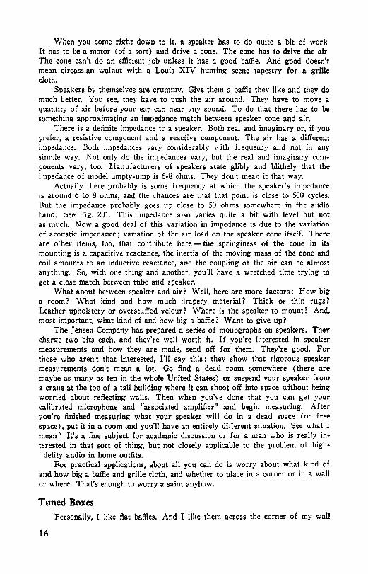
When you come right down to it, a speaker has to do quite a bit of work It has to be a motor (of a sort) a11d drive a cone. The cone has to drive the air The cone can't do an efficient job unless it has a good baffie. And good doesn't mean circassian walnut with a Louis XIV hunting scene tapestry for a grille cloth.
Speakers by themselves are crummy. Give them a baffle they like and they do much better. You see, they have to push the air around. They have to move a quantity of air before your ear can hear any sound. To do that there has to be something approximating an impedance match between speaker cone and air.
There is a definite impedance to a speaker, Both real and imaginary or, if you prefer, a resistive component and a reactive component. The air has a different impedance. Both impedances vary considerably with frequency and not in any simple way. Not only do the impedances vary, but the real and imaginary components vary, too. Manufacturers of speakers state glibly and blithely that the impedance of model umpty-ump is 6-8 ohms. They don't mean it that way.
Actually there probably is some frequency at which the speaker's impedance is around 6 to 8 ohms, and the chances are that that point is close to 500 cycles, But the impedance probably goes up close to 50 ohms somewhere in the audio band, See Fili?, 201. This impedance also varies quite a bit with level but not as much. Now a good deal of this variation in impedance is due to the variation of acoustic impedance; variation of the air load on the speaker cone itself. There are other items, too, that contribute here - the springiness of the cone in its mounting is a capacitive reactance, the inertia of the moving mass of the cone and coil amounts to an inductive reactance, and the coupling of the air can be almost anything. So, with one thing and another, you'll have a wretched time trying to get a close match between tube and speaker.
What about between speaker and air? Well, here are more factors : How big a room? What kind and how much drapery material? Thick or thin rugs? Leather upholstery or overstuffed velour? Where is the speaker to mount? And, most important, what kind of and how big a baffie? Want to give up?
The Jensen Company has prepared a series of monographs on speakers. They charge two bits each, and they're well worth it, If you're interested in speaker measurements and how they are made, send off for them. They're good. For those who aren't that interested, I'll say this : they show that rigorous speaker measurements don't mean a lot. Go find a dead room somewhere ( there are maybe as many as ten in the whole United States) or suspend your speaker from a crane at the top of a tall building where it can shoot off into space without being worried about reflecting walls. Then when you've done that you can get your calibrated microphone and "associated amplifier" and begin measuring. After you're finished measuring what your speaker will do in a dead soace r nr frf';.
space), put it in a room and you'll have an entirely different situation. See what I mean? It's a fine subject for academic discussion or for a man who is really interested in that sort of thing, but not closely applicable to the problem of highfidelity audio in home outfits.
For practical applications, about all you can do is worry about what kind of and how big a baffle and grille cloth, and whether to place in a cvrner or in a wall or where. That's enough to worry a saint anyhow.
Tuned Boxes Personally, I like flat baffies. And I like them across the corner of my wall
16

and ceiling so they squirt downward a bit. And I like them big. I suspect I'd like a speaker mounted right in a wall but I'm not positive. I've heard some sweet-sounding deals that way, but I've never heard the same speaker mounted any other way and I've never owned my own home so I could try it out myself. I've mentioned it but my XYL wasn't enthusiastic, so maybe I never will do it.
I tried tuned boxes for awhile. You know, with a slot cut in them under the speaker opening. I stud:ed the tl:eory of tuned boxes up to the point where I couldn't find out any more information. lV!y conclusion was that there aren't many people who understand what they profess to know about the subject of resonance.
50
40
10
5
INDUCTIVE
J
• I
I
I
I I
, CAPACITIVE -
\ \ \
i-......1
, • IC- INDUCTIVE
~
I ~ I
,/ t
I ~' I __,,,, ....
-;-20 10 1000 10 000
FREQUENCY IN CYCL~S PER SECOND
Fig. 201-Speaker impedance vs. frequency. 8-inch speaker at 1-watt level.
With the simple Helmholtz resonator you have a situation that can be easily understood. Blowing across the mouth of a bottle is the same idea. Resonance is determined by the enclosed volume and the size of the opening. If you want a formula here is one: F = 2,070 (A '4. /V½). This is cycles frequency, square inches area, and cubic inches volume. But that isn't quite the same thing as a speaker box.
Then there's the bass drum idea. The frequency depends on the volume and also on the tension of the drumhead. The tension of the drumhead can be further broken down into effective mass and compliance. Even the stiffest plywood you'd use in a speaker box will have something of this behavior, as you may easily check by thumping on the box and listening for a tone.
An infinite baffle is closer to the bass drum idea, but the analogy isn't too close when what you're after is a tuned box with a slot. The slot makes for a combination between the bass drum and the bottle resonator extremes. The slot will alter your resonant frequency at one end, and the mass and compliance of the cone will alter it at the other end.
This concept was long ago ancl I finally shrugged it all off and went in for empirical design. My speaker was a 13-inch one (an expensive Cinaudagraph) and I finally decided to push all responsibility onto the Jensen people by simply making the box the same size (with the same size slot) as Jensen made for their 15-inch speakers. The back was to slide in and out so I coulcl tune it to where it did the most good for me. A pipe dreamer.
I built the box okay, I'm a fair wood-butcher, and it didn't look untidy but neither did it sound tidy. It was boomy and barrel-tonecl, and the XYL raised her brows at me and it. I decided the Q was too high and it needed padding, so I
17

padded the inside with old sweaters, burlap, old towels, a piece of celotex, and other handy items. That helped a lot.
Then I decided it could be tuned easier if it weren't padded, so I tore the stuff out again and bought a frequency record. I played it over and over while pushing the sliding back in and out to change the resonant frequency.
The conclusion was about what was to be expected: I could change the resonant frequency of the box by altering the volume. Pushing the back in raised the frequency, and pulling it back lowered it. At the resonant frequency there was a big bump in the curve.
The speaker resonance by itself proved to be about 55 cycles, and the box resonance could be altered from about 40 cycles to around 150 or so. When the box was also tuned to 55, the result was terrific. Just touching the pickup made a 55-cycle growl. I decided first off I didn't want to match my resonances.
The speaker fell off below 55 cycles pretty sharply, so I decided to make the resonant point 50 cycles and then pad the inside till the Q dropped low enough to oust the growling tendency. That wasn't hard. Just tedious.
I settled the back in far enough to give the right volume .and then began padding the inside. I'd tap the pickup and listen and then add more padding. The more I de-sharpened it, though, the broader the hump became, and the more padding I added the smaller became the volume. Finally I was back to 55 cycles again and, though broader, the resonant box and speaker still growled damped waves.
So I pulled the back out farther and tried again. I finally got it to the point where the box resonance was pitched just below speaker resonance and tapping the pickup made it go bump instead of boom. "Ha!" I exclaimed in relief. "Now then ••• "
But music didn't sound so hot. It was still a bit barrel-house and tended to boom out when a note came along close to the resonant frequency. I got out the frequency record again and began playing with the slot opening. I had the XYL hold a board over part of the slot while I listened and vice versa.
To make a long story short, I finally bought another piece of ¾-inch plywood for the back. One large enough to butt against the back instead of sliding in and out. I stopped the slot up entirely (from the inside where it wouldn't show) and put in plenty of padding. My resonance was close to 40 cycles and plenty broad. It helped out the low notes a tiny bit but not much.
Stopping up the slot entirely made it into the so-called infinite baffle. It sounded much better to me and to the XYL that way. It wasn't perfect but it was still not bad.
It would be nice to be able to give you absolute design information on tuned boxes, but all I can do is warn you. I don't care for them myself because I believe they distort the response curve too much. If there is enough padding inside so that they don't make a bass drum sound like a plucked bull-fiddle, then I think you're just as well off with an infinite baffle.
I haven't confined my experience to just one. Four others have been called to my attention during the years with urgent requests to make them sound better. The results of my findings are: (1) resonance frequency depends on volume, compliance (springiness) of the sides, effective mass of the speaker cone and voice coil, and (very slightly) on area of the slot itself; (2) the Q or relative boost due to resonance is determined by the amount and placement of padding and the kind of grille cloth; (3) the whole thing is largely subjective and a matter
18

tor your own ears to decide; ( 4) as a generalization, box resonance should be between 10 and 15 cycles below speaker resonance for best results.
Of the four other tuned boxes, three were home-built and the fourth a commercially made affair. One of the home-built ones and the commercial box ended up as my own did - infinite baffles with stopped-up slots and considerable padding. The other two were for customers who decided they rather liked the bass that way, and we followed the same technique as above. No padding in while we pitched the frequency, and then padding until the customers' ears were satisfied. Both had commercial grille cloth over both openings and the slot had an additional layer of toweling behind it. The padding was solid at the back end of the box and very heavy and fuzzy. A layer of toweling covered the rest of the interior, and burlap was tacked over the toweling on the bottom and halfway up each side. The resulting curve in both cases bumped up considerably at the bass end and continued the speaker response to nearly an octave below its normal. Neither the XYL nor myself thought the sound as good as from our own outfit, but both customers were tickled pink when a low note came along. "Man, listen to that bass!" they said admiringly,
All this was long before the war. During the war I worked in a laboratory with some fellows who had experimented with baffles. They agreed entirely as to it being a matter of individual speakers and individual ears, and most of them preferred infinite baffles or flat baffles. They had made a good many of these tuned boxes themselves and had arrived at the set of figures illustrated in Fig. 202.
Fig. 202-Boom box dimensions.
SPEAKER A B C D E F G H I 8" 14¼" 8¾" 20½" 10" 2½" 7" 5½" 5" 7½"
10" 24½" 10¾" 26½" 12" 4½" 8¾" 8" 8¾" 5¼" 12" 25½" 12¾" 28½" 12" 5" 10¾" 9" 8¾" 5¾" 15" 27½" 14½" 31" 14" 5½" 13" 10" 9½" 6"
(Use ¾" stock)
Since then, I have several times been asked to design a tuned box for a 12-inch speaker. It being for love and because they couldn't see any point in running
19

curves on the speaker or bringing it to me, I have just given the dimensions from this drawing and specified loads of padding. Seven have actually built boxes to these dimensions and each one was very pleased. They invited me to come aud listen to how good they all sounded, which I did. I smiled and admired politely and, in truth, they didn't sound bad. Each one had an obvious resonauce that was comfortably low.
For the reader who wants a tuned box and wants it right, I can only suggest empirical design. Make the box large and tune it by a sliding back or some such. Then pad it, and don't spare the burlap. In spite of the rigid specifications of the drawing, I don't believe slot placement is critical. Slot size should vary with cone area.
A curve should be run with any speaker before a box is planned. Or, if not a curve, then at least determine where the speaker resonance is. This can be done by a simple oscillator or a frequency record. It will be obvious. With most speakers you can even see the cone moving to greater amplitudes at resonance. This resonance, you can note, will change if you bring your hand up and load the cone, and the Q will probably be between 4 and 8.
The effective Q of both speaker and box can be appreciably lower (it had better be) with the amplifier source impedance loading the speaker line. One fellow set up a telegraph key and a battery across his line and checked his padding by hitting the key. He said that with a high Q he'd hear a tick-boom, tick-boom from the speaker. The key closed would short the speaker line down to the battery impedance; with the key opened, the line would be open.
It sounds fine, but the amplifier won't present an open circuit at all. Padding his box until he got a tick-tock instead of tick-boom when he worked his key meant he had lowered the Q until he had the equivalent of an infinite baffle.
This business of a shunting impedance is really important. Forget box resonance for a moment and just consider speaker resonance. If you want smooth response, you must avoid the unpleasant hoost where resonance lifts the speaker impedance sky-high; and you can do that with a low-impedance source. If you have a pair of 2A3's in push-pull, you have a source impedance of ahout 1,600 ohms which is stepped clown by a 5,000-ohm to voice coil transformer. This will place about 2.5 ohms of impedance across the voice coil terminals.
With a pair of 6L6's in your output, you have then a source impedance of 40,000 to 50,000 ohms. You shunt this clown to about 5,000 ohms with an RC strap, which means you strap the voice coil with about 8 ohms. This is further explained in the amplifier section.
You can lower this impedance by using inverse feedback on the amplifier; and, with beam tubes, it's almost necessary for lots of other reasons. The fact remains that triodes with feedback give lower shunting impedances than beam tubes with feedback. But that will be taken up later.
Labyrinth The purpose of the box around the speaker is to improve the low response, and
one of the dodges has been to couple a sort of labyrinth to the back end of the cone and have it twist around so it comes out in front again and favors the low notes. This has been more popular in the past than it is now.
Some speakers of this type have approximated a horn in that they increase the area the farther they go but, so far as I can find out, this isn't much better than a plain tube. At least for all practical sizes. The tube will give a pretty fair load on
20
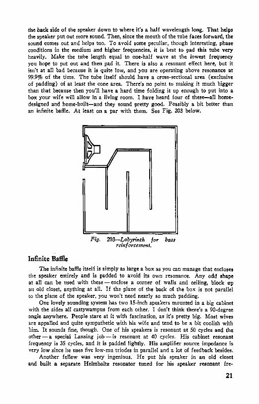
the back side of the speaker down to where it's a half wavelength long. That helps the speaker put out more sound. Then, since the mouth of the tube faces forward, the sound comes out and helps too. To avoid some peculiar, though interesting, phase conditions in the medium and higher frequencies, it is best to pad this tube very heavily. Make the tube length equal to one-half wave at the lowest frequency you hope to put out and then pad it. There is also a resonant effect here, but it isn't at all bad because it is quite low, and you are operating above resonance at 99.9% of the time. The tube itself should have a cross-sectional area (exclusive of padding) of at least the cone area. There's no point to making it much bigger than that because then you'll have a hard time folding it up enough to put into a box your wife will allow in a living room. I have heard four of these-all homedesigned and home-bt1ilt-and they sound pretty good. Possibly a bit better than an infinite baffle. At least on a par with them, See Fig. 203 below.
Infinite Baffle
~ 9
--Fig. 203-Labyrinth for bass
reinf orcentent.
The infinite baffle itself is simply as large a box as you can manage that encloses the speaker entirely and is padded to avoid its own resonance. Any odd shape at all can be used with these - enclose a corner of walls and ceiling, block up an ol<l closet, anything at all. If the plane of the back of the box is not parallel to the plane of the speaker, you won't need nearly so much padding,
One lovely sounding system has two 15-inch speakers mounted in a big cabinet with the sides all cattywampus from each other. I don't think there's a 90-degree angle anywhere. People stare at it with fascination, as it's pretty big. Most wives are appalled and quite sympathetic with his wife and tend to be a hit coolish with him. It sounds fine, though. One of his speakers is resonant at 50 cycles and the other -a special Lansing job- is resonant at 40 cycles. His cabinet resonant frequency is 35 cycles, and it is padded lightly. His amplifier source impedance is very low since he uses five low-mu triodes in parallel and a lot of feedback besides.
Another fellow was very ingenious. He put his speaker in an old closet and built a separate Helmholtz resonator tuned for his speaker resonant fre-
21

quency. This resonator was a simple wooden box with a hole in it and absorbed the resonant frequency nicely. The formula for such a resonator is F=2,070 (A¾ /VY.) - the same formula discussed before.
A lot of fellows don't care to do away with their speaker resonance because it does give them more bass. If the speaker is large enough so that its resonance is quite low, this is fine. A plain ordinary infinite baffle here is fine without too much padding. Just make it large enough so that the cabinet resonance will occur just below speaker resonance. Five to ten cycles below is about right to broaden the bass bump; and, if it is too obvious, you can always put in a little padding.
The frequency of these boxes comes pretty close to the bass drum deal. That is, the frequency is determined by volume and also by the compliance of the cone or the effective mass of cone and voice coil. These masses vary with different speakers quite a bit. Even two speakers of the same size and manufacture will have different effective masses.
Since effective mass is a difficult thing to determine and since it doesn't seem to be given in speaker advertisements, it is impossible to give you any reliable, absolute information on all this. I could give you a curve for volume necessary for F frequency with G grams of effective mass and D diameter of cone, but I don't know where you'd go from there. I finally determined that my large speaker has an effective mass of 0.86 ounce, but it was a long hard job and I'm not at all sure of the rigor in measurement.
For best results make your volume a bit more than you think necessary and then cut it down by shoving in the back of the cabinet. For good results you can safely follow this table of speaker sizes and volumes:
611 speaker 4 cubic feet 8" " S½ " "
10" " 6¾ " " 12" " 8 " " 15" " ....... 10 " " 18" " ....... 12 " "
This kind of a box shouldn't, of course, be called an infinite baffle. It is actually a tuned box; but if you call it a tuned box, people confuse it with that other deal with the slot under the speaker opening. An infinite baffle should be the name of a very large flat baffle - infinitely large even at the lowest frequency that you are interested in. This isn't that. This is a simple tuned box that will slightly reinforce the bass notes. The whole thing is a matter of what you want.
Next to a flat baffle I like this sort of a thing myself, but padded so much that resonances don't show up. The reason I prefer a flat baffle is that there you have only the speaker resonance to worry about. A flat baffle also provides a way of compensating for the speaker resonance.
Flat Baffle Whenever you say flat baffle to a high-fidelity enthusiast, he generally winces
a bit, and he has good cause. The typical flat baffle is completely unimaginative and sounds rather poor. A square board with a hole in the middle - it doesn't even look good.
Let's look into the matter of what a baffle does. It keeps the sound from the back side of the cone from mingling with the sound from the front side. A sound wave is really a sort of train of dense air followed by a mass of rarified air. It's a pressure wave, first high and then low. The speaker cone pushes and compresses a
22

mass, and then it pulls back and rarifies another mass. Now if a mass of high pressure from the back side of the cone should get around the edge of a flat baffle just as the cone is pulling back to make a rarified mass of low pressure ( toward a vacuum), the two masses tend to cancel each other.
The cone pulls back, and immediately a pressure wave comes from the back of the cone traveling out into whatever space it can find. As it races around to the front, the speaker cone has pushed forward and, just as the high pressure gets there, is ready to pull back again. The pressure wave takes the shortest path it can find, and in a small square baffle it has four sides to get around so there's quite a bit of cancellation where the length of path is one wavelength.
The wavelength of sound varies with frequency - varies inversely. The lower the frequency, the longer the wavelength. See Fig. 204. The longer the path from back to front of a baffle, then the lower the frequency at which the waves will cancel each other. At that frequency, with a square baffle, you might as well have no baffle at all. The only baffle that could be worse would be a round one with the hole in the center.
24
22
20
18
0
6
4
2
• ' ' .. '
' ' ' ' .. '
'" ,.....
i
... ... .. -
I
I
I
24
u 20
8
5::l 4~
i!: I 213
z I 0~
!!;! 81 8
4
2
0 0 ZO IOO FREQUENCY IN CYCLE~~iR SECOND IO,OOO ZO,OOO
*FOR FCET USE LEFT SCALE * FOR INCHES USE RIGHT SCALE
Fig. 204-W ave length in feet and inches vs. frequency.
Since it's a matter of wavelength compared to path length, we can improve matters terrifically by mounting our speaker off-center. If you are limited to a square baffle, then by all means abhor the center of it. We can further improve matters by making our baffle larger at the same time.
Furthermore, if we can use ceilings and walls to block off the path from back to front in a direction or two, we'll be just that much farther along. We can't get away from the fact, however, that there'll be a dip in response where path length equals one wavelength. Also where path length is one-half wavelength.
By makiitg our flat baffle large we do more than merely lower these dips. If the baffle is across the corner of ceiling and wall (as mine is) and is large, then the sound from the back side of the cone is fairly well isolated from the front of the cone. Even if some of the sound is cancelled, some will still get to the ear.
23

I use that dip to cancel the bump of speaker resonance. I did it once with a couple of accordion-edge speakers in a 4-foot by 8-foot chunk of plywood. I mounted the speakers so that there was a path length from back to front of 7 feet 8 inches, which is the length of a half wave at 73 cycles. The resonant speaker bump there was almost completely cancelled by the baffle anti-resonance. Of course where 7 feet 8 inches amounted to 1 wavelength (146 cycles), I had a dip which had to be boosted to be gotten out; so when I built another outfit, I bought more plywood and made the path equal to 15 feet 4 inches. The dip was greater even with the ends of the plywood farther apart, so I had to make a bit more boost at resonance to come out even. This I did with a little current feedback alongside the more usual voltage feedback in the amplifier. That raised the source impedance and let the speaker resonance curve show up just enough to cancel everything,
I cut my speaker holes symmetrically and then wondered because one speaker resonated at 72 cycles and the other at 74. I was prepared to hear a double humped resonance but I didn't. The curve is lovely and smooth all the way down to nearly 60 cycles. That is very low.
There is another advantage to having two speakers mounted close together in the baffle. Each cone helps load the other appreciably, and the efficiency goes up a bit. They are phased, of course. I tested the terminals with a flashlight battery to make sure they both pushed and pulled together. I prefer to add them in series rather than parallel because that way needs less step-down in the output transformer and gives more voltage for inverse feedback.
I am very partial to multispeaker installations. Just the very randomness of their small variations (which vary greatly from speaker to speaker) will tend to add up to a smoother response. One installation I know consists of five accordionedge speakers and five smaller cone speakers with varnished cones. They are all clustered around the center of a very large flat baffle and fed by a 60-ohm line. The main resonance is, of course, 73 cycles, and the baffle is cut for an anti-reso• nance by means of a 15-foot, 4-inch path length from back to front. The smaller speakers resonate around 165 cycles, so small slots were cut in the baffle to make path lengths of 6 feet 4 inches. Then we ran curves and filed away at these slots with a wood rasp until the bump dropped out. It is a good deal although rather bulky. We had a small bump around 800 cycles, which for some reason we hadn't foreseen, but fixed that by drilling some holes about 9 inches away from the speaker holes. These made for a slight cancellation (and hence dip) at 800 and a slighter one at 400 (one-half wavelength), but we worked out a very nice compromise and ended up with a curve that is within 3 db from 55 cycles clear up to 9,200 and smoother than a double-horn Shearer system.
As to brands of speakers, I don't know. There are separate individualities to speakers that look like twins. Just because one ZZ-3 resonates at 66 cycles doesn't mean another ZZ-3 won't wave its arms at 62 or maybe 70 cycles.
I don't like to buy a speaker by catalog or by advertisement. I buy across a counter and with the understanding that I may return it if it should prove to be unsatisfactory. I try to pick out speakers with heavy, thick, soft cones, as they are less likely to break up in excursion with consequent harmonics. I like to lacquer them to guard against their picking up too much moisture. I like a big heavy magnet because that means greater flux density and hence higher efficiency ( unless clearances are such you can throw a cat through there).
There's no question about the larger speakers doing better at the bass end.
24

Resonance is lower and cones heavier. Smaller excursion means less breakup with consequent harmonic generation. They push more air around. So, whenever you plan on a two-speaker installation, don·t neglect these big fellows.
Dual Systems Back around 1940 Jensen became a bit enthusiastic about coaxial speakers
with the small tweeter mounted inside the larger cone. In any deal you just about get what you pay for, and in this one you get wider frequency response for your extra hard-earned cash. They had several models, and the difference was mostly efficiency plus a matter of a control for adjusting the high cutoff. The crossover frequency was about 1,200 cycles, and there was no divided presence because the speakers were coaxial.
Divided presence is the sensation of hearing the sound coming at you from two different sources. Most folks find this very unpleasant.
For years before this, sound men had considrred the ultimate to be something like the Lansing Iconic system -- a boom-box and horn cluster arrangement. This was quite expensive so the audio hounds greeted this Jensen coax with great enthusiasm. They were disappointed because a $75 rig didn't do as well as a $250 one. They were wrong in this. Coaxial speakers are nice though not as nice as a good two-way system.
Most of the trouble is that a single speaker will put out highs only in a sort of fine stream - the higher, the finer. The result is generally that you don't get treble till you're squarely in front of the speaker and then you get too much. The Jensen is just as bad as a single speaker in this feature. After all, one speaker puts out highs.
The larger two-way systems are much better. They should be at those prices. They consist of a woofer in a tuned box and then a cluster of horns that fan the highs out. The horns are of course driven by a separate H.F. driver.
Audio men have knewn of these for years and wanted them. For a while you could pick up Western Electric 555 drivers quite cheaply. These were for the horns and had a 6-volt field which we usually rewound to fit a more conventional supply, The better ones had voice coils of aluminum ribbon wound on edge, and the response went right up to about 12 kc before they fell off. They were satisfactory down to about 200 cycles too, but most fellows had their cutoff around 500 cycles or so.
There were other drivers floating around too (and still are), some of them PM but not many. I was offered a PM Western Electric 555 for $7.50. Ordinarily you pay more than that for one with a magnet.
Horns With horns as expensive as they are, a lot of fellows wonder about making
their own. Well, it's possible. I did it. I promoted a bunch of old gasoline cans and did tin-snip and soldering, but it's a lot of work. The design is simple, but making the horns is worth fully as much as they charge.
Horns can be of many forms but the best for sound is the exponential. The straight-sided horn (as a megaphone) is much easier to build, but the bass response really falls off. The exponential horn carries down very nicely to a cutoff determined by flare. The formula (equation if you prefer) is simply this:
S:i:: =Siems, where S:i:: = cross-sectional area at point x, S1 = cross-sectional area at throat,
25

e = 2.72, m = flare constant that determines the cutoff frequency of the horn, x = the C:istance from the throat to where Sx is the cross-sectional area.
A horn whose area doubles every 12 inches will have a cutoff frequency of 64 cycles. Also, a horn whose area doubles every 6 inches will cut off at 128 cycles. We have learned that a horn does well only if we allow a distance of a wavelength (at the lowest frequency we are interested in) around the mouth of the horn. Less than that gives much distortion and poor response.
All right. We can now design a horn for just about any frequency we want. As you can easily see, the lower the cutoff the larger the horn For tweeter use we will most probably want a throat area of around ¾ square inch and a cutoff of close to 300 cycles. Lower is nice but it gets pretty big. Lots of outfits have smaller horns, but - well, let's pick 300. We can make our crossover at 400 or 450 then.
From the 64-cycle cutoff for a 12-inch doubling horn we can settle matters nicely by simple proportion. 64/D = 300/12. From this we get D equal to about 2.23 inches. Just double our area each 2.23 inches and our horn will cut off at 300 cycles.
~ ~ .. 5 :;i ~ "' !. :$ ., "l ,;
.l T
Dl!ENSIONS IN INCHES
Fig. 205-Profile of exponential horn. All dimensions in inches.
From this it might be possible to build a horn, but for best results we should be able to determine sizes oftener than each 2.23 inches. For high frequencies to be clean and nice, a little more precision is needed. So we can use our horn equation : Sx = S1 em•.
First we must solve it for (m). Our throat area will be ¾ square inch, and 2.23 inches farther away it will be double that or ¼ square inch. In other words :
¼ = ¾ X 2,722.2sm which will work easier if we multiply both sides of the equation by 4.
2 = 2.722.23m
and now we will take the logarithm of each side. Log 2 = 2.23mLog 2.72
which we can look up in a table and get: 0.301 = 2.23m X 0.435 = 0.971m.
Now just divide by 0.971 and we get: m = 0.301/0.971 -= 0.309.
26

Now we have an equation for this specific horn ;S., = l / 4 X 2,720.aoos This. of course, can be solved for any distance X from the throat to get the area at that point. This horn is computed for cross-sectional area at each inch. Then, if you want a square horn, as most do, just take the square root of those figures to get your dimensions at each inch. This is done in the accompanying Table 2-1, and the profile of the horn itself is shown in the graph, Fig. 205.
TABLE 2-1-DATA FOR EXPONENTIAL HORN-CUT-OFF AT 300 CYCLES
X inches Sx = square inches Width at X for square horn
1 0.340 0.583 2 0.465 0,682 3 0.632 0.796 4 0.863 0.930 5 1.173 1.084 6 1.602 1.267 7 2.188 1.481 8 2.980 1.729 9 4.07 2.02
10 5.54 2.36 11 7.54 2.75 12 10.30 3.21 13 14.01 3.74 14 19.06 4.37 15 26.1 5.11 16 35.5 5.96 17 48.3 6.95 18 66.1 8.13 19 89.8 9.48 20 123.0 11.10
Sx = S1 em• where S1 = ¼ square inch throat area e = 2.72 (Napierian Base)
m = 3.09 (flare constant for this horn)
x = distance from the throat in inches
Sx = area of horn in square inches at distance x
This same procedure can be followed for a horn of any cutoff frequency desired. Using this technique, I designed a horn for a SO-cycle cutoff.
The calculation is easy. Building the horn is harder. For high-frequency use you want more than just one horn-at least eight (two high and four wide), all clustered to a common throat and a common driver. This spreads the treble around beautifully.
Just making the eight horns isn't enough either. After soldering them together, make a metal case to go around them and pour the spaces between the horns full of tar to avoid resonances in the metal. It's really quite a job to do all
27

this, And they can be bought - all nicely built up - for around $40, used, if you shop a bit. I got a used one for $20 just before the war.
The ones supplied by Lansing and Jensen and other companies are usually smaller than this. They use a higher crossover. That's all very well if you are listening from farther away than my living room permits. When you are close to them, however, you might be conscious of a divided presence of sound, which can be annoying as all get-out. For this reason a low crossover frequency is desirable since then more of the notes will be coming from the horns rather than from the speaker. The speaker will put out a good deal more bumps and hollows as well as a bit more distortion than the horn will- another good reason to have most of the stuff coming from the horn.
That's why most fellows prefer a little longer (lower) horn than that supplied with most of these commercial outfits. If you're handy with snips and a soldering torch, you can build your own, or, if you feel flush you can have it built at a local sheet-metal shop. Work out the design figures yourself and draw it up carefully and, to help out, show them a photograph or a drawing of one of Lansing's or Jensen's units. They'll make it all right.
These high-frequency drivers are generally around 16 ohms or so in impedance and so are most of the large speakers that fellows get for the bass. Since they are the same that makes the crossover network easier to design.
Crossover Networks There are two main types of crossovers : the constant-impedance and the m
derived. They are further divided into parallel and series types. The diagrams, formulas, and curves for the m-derived networks are shown in Pig. 206 and Fig. 207.
PARALLEL TYPE SERIES TYPE
z.
LI• 2~Tc° HENRIES
L2• ( l+ml 2;\c HENRIES
lt3 LI ~REQSPKRS
7 " " "'""""' · II o
Cl• 2'fr~6 Zo MICROFARADS
I 106 C2• tl+m> • a'IT fc Zo MICROFAR~S
I Zo L3• o+m> • 2 ll' fc HENRIES
106 CJ• U+111 ) • Z'IT fc Zo IAICROFARADS
fc • CROSSOVER FREQ Zo • IMPE~NCE OF LINE & SPKRS m• ,6 FOR OPTIMUM IAATCHING
Fig. 206-Design of m-derived crossover networks.
This crossover network business may seem tricky. A lot of people think the pass-band should go right up to the crossover frequency and then stop- boom! Not so. It's not only too expensive but it doesn't sound as nice. Take it easy. Not more than about 18 db per octave at the most.
28

Don't let these figures frighten you. Like most other things these crossover networks are easier to design than they are to build. The scariest thing in the line-up is this "m" business. It's just a term. Regard it as a <limensionless quantity and you'll be all right. I've designed many filters over a lot of years and use<l m many times without knowing what it stands for exactly. Varying its value varies your impedance match and the sharpness of the cutoff. A good value of m here is 0.6. Just substitute 0.6 for it and let it go at that. Asked to define m, engineers and physicists and electronics teachers double-talk and hem and haw about it and then wander off into the semantics of it. Just regard it as 0.6 and you'll be okay.
2
4
8
2 0
.2 .4 f/fc
,6 ,8 I 8 10
r-i-,."' /
\
' \
' \ I \
j \
' \ \
I \
Fig. 207-Attenuation characteristic of m-derived crossover network.
If we figure a parallel type for average use, it might help. Let's call the impedance 16 ohms (a most likely value) and the crossover 500 cycles, and see what values we come out the back encl with:
16 ----- = .0051 henrys (5.1 mh),
6.28 X 500 L2 = 1.6 x .0051 = .00816 henrys (8.16 mh),
1,000,000 C1 = ------ = 19.9 microfarads,
6.28 X 500 X 16
1 C2 = -- x 19.9 = 12.4 microfarads.
1.6
The tough part comes in the promoting of those capacitors. They should be paper and can be made up from a bunch of small ones if you like. For the sake of accuracy go to a technical school and get a bridge to check them and also the coils. Their smallness makes them easier to wind, but their inductance is fairly critical.
The constant-impedance networks have slightly less steep curves and have the further advantage in mass production of requiring the same sizes of coils and capacitors. Here, in Fig. 208 and Fig. 209, are the formulas, diagrams, and curve of the constant-Z type.
29

Here too we witl need rather large size capacitors and they must be paper. Don't use electrolytics. The low-impedance line requires low reactances, and that means small coils and large capacitors.
Zo
PARALLEL TYPE
Ll:l,414X + HENRIES 2 II fc
Cl• _I - X ~ MICROFARAOS 1,414 2 11 fc Zo
fc • CROSSOVER FREQ
SERIES TYPE
~~-! ~ " ~ ""'." ..... L2, _I X Tl'Zo HENRIES
1,414 2 fc
C2 • 1,414 X 2 ~~: Zo MICROFARAOS
Zo • IMPEDANCE OF SPKRS & LINE
Fig, 208-Constant impedance crossover networks.
There's still another way around this crossover network business, one that appeals to slim pocketbooks. That is to have two complete output channels on the amplifier and do the crossing-over back where impedances are high and power is low. That way we can get by with simple resistance-capacitance filters in each channel and so avoid the expense of these larger units.
There is even more to recommend that practice. We can use a large amplifier for the bass end where we need the power and just a little dingbat for the treble where we don't. This is particularly true when horns are used on top, because horns step up efficiency about four times. Another advantage is that cheaper output transformers can be used since neither has to pass such a wide band, The method of doing that will be shown in a later part of the book.
These double-speaker outfits are very good. If you can afford to buy one •• , fine. If you can't and you still want a really nice-sounding outfit, you'll probably make-do and you may even end up with something that sounds considerably better than a regular job.
Most of the trouble with these commercial affairs lies in the bass end, Their response is down for a lot of reasons, and prominent among them is the simple fact that for production reasons it is not feasible to take individual speakers and give each of them its ideal tuned box. Also customers are a bit chary about how much space to allot to a speaker.
About as nice results as anyone ever could want can be had by using a great big infinite baffle with at least two 15-inch speakers in it, and then on top having a horn cluster driven by one of the PM drivers. Pitch the crossover fairly low. By the time you finish you'll have spent considerable money and a lot of weary hours, but you'll have something that will give pleasure for many years.
One of my dreams is some day to have a big place out in the country. I will make a low-frequency horn (cutoff about 50 cycles or so) and put it across the canyon on a hill pointing straight at my front porch. I will run my speaker line right over there from the amplifier. That ought to sound fine. I did build just such a horn once in a garage. It sounded lovely, but neighbors and the police objected to the amount of sound that came out. It was approximately 7 feet long
30

and its mouth was about 7 feet square, but it had the cleanest bass I've ever heard outside of a recording stage. It was driven with a pair of 2A3's, and the police claimed they had complaints from folks clear over in Santa Monica ( over a mile and a half as the pelican flies), and we finally had to move. We were packing up for the moving when an old Scotsman with bushy white eyebrows walked all the way over from Santa Monica to tell us how much he had enjoyed the concert and what a shame we were moving. I had played a lot of bagpipe records on it.
Construction wasn't so tough. I made it from ¼-inch plywood. And I still like the idea fine. At one time I thought of making a whole wall of a house into such a horn but the trouble there is that it squirts such a fine stream of high notes.
,I ,2 ,4
j I
J I
I
f/fc ,6 ,8 I ,...,~
, /1'
I '\. • \. ,
\ I '
4 8 10
\ \ \ ,
Fig. 209-Attenuation characteristic of constant impedance crossover network.
Sound stages and movie theaters use bass horns, but they fold them. Low frequencies will turn corners all right, and it does save some space but not enough. The horns used in most theaters are about 10 feet high and 12 feet wide. That's still too large for even a large house. Every once in a while a smart lad gets an idea about using the walls and floor of a room to form parts of the sides of a horn for a living room. The idea is fine as far as it goes. A horn is nice as can be, and if it takes up a lot of space, why not use walls and floor?
Phasing Well, the trouble with that is simply this: the fellows go whole hog and get so
interested in saving space that they lose sight of such important points as how it sounds. Some smart and ingenious chaps have designed beautifully intricate structures for a folded bass horn in a corner, but there's a string tied to it. There usually is a string somewhere.
Let's look for a moment at the big speaker installations used in the better theaters. They spend money like mad for these outfits and they sound lovely. They use a large folded horn for the bass and a straight horn duster for the high notes.
Sound experts in Hollywood evolved the Shearer horn system some time back, and one of the really important features in the design is the phasing. They found they had to keep the path lengths through the horns close to the same dimen-
31

sion in order to avoid a kind of phase distortion that can certainly be heard and disliked.
The distance across the mouth of those big horns is about 80 inches, which amounts to a mouth area of 6,400 square inches. For a 50-cycle cutoff (which is commonly used) the area doubles every 15¼ inches so you might say they have a certain license in clesign: they can make a fairly short horn by using a very large throat opening, or they can make the horn longer and have a smaller back opening (and use a smaller speaker). Actually they use four 15-inch cone speakers to drive these big horns. They really don't need all that power. of course. With the step-up in efficiency clue to the loading of the horns they could easily use just one speaker in most houses. They use four speakers because then it is possible to get by with a shorter horn. Using a 30-inch square throat, they mount all four of these big speakers there. They fold the horns, too, but that's merely to keep the physical size down to convenient dimensions. The path length is kept short deliberately in order to match the path length of the treble horns on top. The four big speakers make for a total path length of around 44 inches.
Why do you suppose they would go to all this trouble and expense? Right the first time! They have to in order to make it sound right. H there is an appreciable difference in the path lengths of the two sound sources, they get into a terrible fuss. Sustained tones still sound fine, but short, sharp staccato notes terrible. Fuzzy. When notes approach the limit of shortness as when rred Astaire hoofs it, the sound is very bad. Fuzzy and soft and often doesn't appear to come from the screen at all but off to one side. Tlzey hm·e to have close to equal path lengths or the result w1111't sound right.
Now this is true and honest, but hard for some folks to accept. The smaller twin-speaker jobs do have a certain path-length difference and maybe that's one of the reasons they are less than perfect. The difference is small, however, since the treble horn is short and the woofer is just in a boom-box.
Let's get back to our smart boys who foltl their bass horns to stick in the living room corners. They fold up the bass horn which is fine, and they are very clever about using walls and floors as sides of the horn, which is ingenious, but they always have a fairly long path length for the sound to follow before it gets out. Now what do they do? Do they set up a system of treble horns with the same or close path length? No, they use a conventional short treble horn or even a series of small crystal speakers or something like that.
Anyhow the result isn't so hot. On organ records it isn't bad at all - the bass notes come booming out beautifully. But play that one section of Tschaikowsky's Fourth with all the pizzicato strings, and it sounds crummy. I have heard only one of these outfits, so maybe you shouldn't take my word on this, but I thought it was terrible. Apparently the owner wasn't pleased, either, because he soon changed over to a big flat baffle instead and likes it much better. This was in spite of the lovely bass tones that came out of his folded horn. The phasing is screwed up on these.
We've been a bit negative on this speaker business for a while, so let's go positive for a change. Here is a cut-rate system that can sound wonderful. Earl Grant, who worked at the University of California Lab during the war, fixed up a really sweet speaker system for himself with a remarkably small cash outlay. He was after a home-built equivalent of a boom-box and horn-cluster arrangement. He felt he C0\1lcln't afford a horn cluster for his highs, so he got a good idea about using some small speakers (3-inch or so) fanned out to squirt their highs all
32

around the room. He rigged it all as shown in Fig. 210, and it sounded especially nice.
The little speakers for the treble notes are fairly ordinary stuff, but he gave the cones several coats of lacquer to make them move more as pistons and to prevent their absorbing moisture. He ran them in series and used a crossover network pitched close to 500 cycles. His woofer was a 10-inch job in a tuned box and could have been improved slightly, but his highs were wonderful. He also paid attention to his amplifier and other sources of distortion and the over-all result was much better than many very expensive rigs.
If you'd care to do likewise (and I recommend it highly), pick your speakers carefully and run curves. The little speakers aren't expensive, and the more you stack up in series the smoother your curve is likely to be. I'd suggest at least four (and more) if you can manage it.
Fig. 210-Tuned box cmd tweeters.
Buy a frequency record if you can't borrow an oscillator, and you can well afford to spend a lot of time listening. A word of caution here: anytime you hitch up several speakers to the same line you should phase them, Make sure they all push forward at the same time and pull back at the same time. Don't go by the way the voice coil leads are. Get a flashlight battery and test each speaker with it until you can see that a positive pulse on the line pushes the cones all the same way, Mark the terminals on each speaker, because it will sound horrible if one is pushing when another pulls.
This idea calls for judgment on your part. I'd suggest hinging the small baffles together and swinging them around as you listen until you get the smoothest response in several parts of the room. Don't try to carry the sound down too far. Unless you plan on listening within 5 feet or less, 300 cycles is about low enough.
Multiple speakers are good for the woofer also. It's smoother and each of the cones has an easier job, which means less distortion, Two 8-ohm cone speakers in
33

series make 16 ohms and four tweeters with around 4 ohms apiece will come out about the same and will let you use a standard crossover network if you wish. If you wind your own, then you can make it any value you wish. The result won't be quite as good as with a horn cluster on top, but it will still be very nice.
The next step up from there, both in quality and price, is a regular horn-andbox combination. All this stuff is the same way: You pay through the nose for the last little mite of high fidelity. Everybody should draw his line somewhere. If I didn't have a fairly nice speaker outfit in my living room now, I'd probably draw the line at the same sort of installation in the play room : a couple of accordion-edged speakers in a whacking-big piece of plywood. The difference in price between that and my fancier outfit is nowhere near commensurate with the difference in quality, But then I'm older now, and sadder.

Chapter 3
Power Amplifiers
T HERE'S been more paper spoiled on the subject of amplifiers than any other component of the home phonograph. This is probably because more is known about amplifiers and the most progress has been made in them. It isn't at all difficult to design a marvelous amplifier. Or to build it either. It's the easiest part of the whole system to clean up. Frequency response, distortion, dynamic range, power output - they are all much easier to handle in an amplifier than anywhere else. Equalization is possible here to such a degree that you may compensate for faults in speakers and sources. The amplifier is lovely.
With so much written on amplifiers there is no necessity to go into the fundamentals of amplifier design or hookup except where a point has been overlooked in most books and articles on the subject. In case you are fuzzy on some of the points missed, you might well consult any of the standard works on radio theory. Quite probably most of you already have pretty strong ideas about just what the ideal audio amplifier should and should not contain.
In design I always start at the back end (the speaker end) and go forward For that reason I'll talk about amplifier components in that sa,me order. For those of you who start at the mike end and work toward the speaker - well, you can start at the back end of this chapter and work back.
Power Output In the first place we take up the amount of power output required. I don't
agree with a lot of salesmen and ad writers about this. What reason is there for having 20 watts of clean audio in my amplifier? For a skating rink - well, maybe - but all I have is a small living room and I want to be able to stay in it when records are being played.
You can believe this or not, but it's the truth: I can't stand over 5 watts of amplifier output fed into my speakers. Anything over that drives me out of the room. I measured my amplifier output into a resistive load (equal to 15 ohms) when the gain was set as loud as I could take it. The needle barely touched 5 watts. And that isn't acoustic energy either. That's the sort of power the salesmen talk about when they mention 20 watts. They don't mean 20 watts of acoustic power. It's an even money bet that the speakers on those 20-watt jobs wouldn't put out an honest 1 watt without distorting.
I think the average power of my rig is a little under one-half watt. And that's still electrical power and not acoustic. The records and broadcasts carry an
35
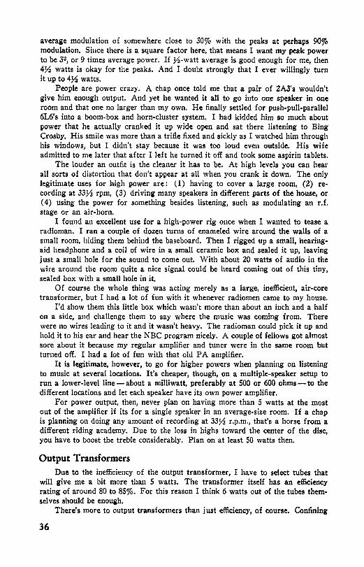
average modulation 0£ somewhere close to 30% with the peaks at perhaps 90% modulation. Since there is a square factor here, that means I want my peak power to be 3~, or 9 times average power. If ½-watt average is good enough for me, then 4½ watts is okay for the peaks. And I doubt strongly that I ever willingly turn it up to 4½ watts.
People are power crazy. A chap once told me that a pair of 2A3's wouldn't give him enough output. And yet he wanted it all to go into one speaker in one room and that one no larger than my own. He finally settled for push-pull-parallel 6L6's into a boom-box and horn-cluster system, I had kidded him so much about power that he actually cranked it up wide open and sat there listening to Bing Crosby. His smile was more than a trifle fixed and sickly as I watched him through his windows, but I didn't stay because it was too loud even outside. His wife admitted to me later that after I left he turned it off and took some aspirin tablets.
The louder an outfit is the cleaner it has to be. At high levels you can hear all sorts of distortion that don't appear at all when you crank it down. The only legitimate uses for high power are: (1) having to cover a large room, (2) recording at 33¼ rpm, (3) driving many speakers in different parts of the house, or ( 4) using the power for something besides listening, such as modulating an r.f. stage or an air-horn.
I found an excellent use for a high-power rig once when I wanted to tease a radioman. I ran a couple of dozen turns of enameled wire around the walls of a small room, hiding them behind the baseboarcl. Then I rigged up a small, hearingaid headphone and a coil of wire in a small ceramic box and sealed it up, leaving just a small hole for the sound to come out. With about 20 watts of audio in the wire around the room quite a nice signal could be heard coming out of this tiny, sealed box with a small hole in it.
Of course the whole thing was acting merely as a large, inefficient, air-core transformer, but I had a lot of fun with it whenever radiomen came to my house.
I'd show them this little box which wasn't more than about an inch and a half on a side, and challenge them to say where the music was comi11g from. There were no wires leading to it and it wasn't heavy. The radioman could pick it up and hold it to his ear and hear the NBC program nicely. A couple of fellows got almost sore about it because my regular amplifier and tuner were in the same room but turned off. I had a lot of fun with that old PA amplifier.
It is legitimate, however, to go for higher powers when planning on listening to music at several locations. It's cheaper, though, on a multiple-speaker setup to run a lower-level line - about a milliwatt, preferably at 500 or 600 ohms - to the different locations and let each speaker have its own power amplifier.
For power output, then, never plan on having more than S watts at the most out of the amplifier if its for a single speaker in an average-size room. If a chap is planning 011 doing any amount of recording at 33¼ r.p.m., that's a horse from a different riding academy. Due to the loss in highs toward the center of the disc, you have to boost the treble considerably. Plan on at least 50 watts then.
Output Transformers
Due to the inefficiency of the output transformer, I have to select tubes that will give me a bit more than S watts. The transformer itself has an efficiency rating of around 80 to 85%. For this reason I think 6 watts out of the tubes themselves should be enough,
There's more to output transformers than just efficiency, of course. Confining
36

outselves strictly to amplifier components, the output transformer is probably the bottleneck. The average listener just doesn't have the facilities available for testing these. Plus that, he has a natural tendency to believe what he reads. Also, the sales departments of many popular transformer firms aren't too careful about what they say.
Back in 1943 I had occasion to run tests on a great number of so-called highfidelity transformers from all the popular companies. We were after the utmost in fidelity for listening to submarine noises. Of them all only two brands gave a transmission curve to match their published ads. I was amazed, but since then I have stuck to one of those brands myself. All the others claimed marvelous response curves and showed graphs that looked as though they had been drawn with a straight-edge from 20 cycles to 20 kc. Maybe they had been. The transformers cut off anywhere fro111 40 to 80 cycles on the bottom and from 8 to 12 kc on the top. They had unbalance and ha1·monics and all sorts of evils,
:Maybe the companies have improved since then. It isn't particularly hard to make a really decent output transformer, and I'm sure they'd do it if they weren't afraid they'd lose business to their competitors who sell for a bit less.
So what are you to do? Well, for one thing you can buy a transformer across a counter and insist on return privileges. Run a curve on it and take it back if it doesn't live up to its claims. Insist on the store raising hob with the company. It'll take a while but you'll eventually get a good one. Just be suspicious.
Now the transformer you have in your amplifier that you bought for a HiFi model may be a stinker. If so, you can send it back to the company yourself with a brisk note. If you don't get satisfaction, a Better Business Bureau will make them behave.
To test a transformer is simple if you have an amplifier. Hitch it in and see how it does. Run curves and check distortion levels.
If you haven't a transformerless amplifier, you can still make a quick, easy check with a regular impedance bridge such as can be found at almost any technical school or laboratory. The items to measure are primary inductance and leakage inductance. These inductances have reactances, and the frequency response is determined by the way these reactances stack up alongside the source impedance.
The bass response is set by the primary inductance and the impedance you strap across it. Examine Fig. 301 below. An equivalent circuit shows clearly that at
INDUCTANCE OF 11c PRIMARY• X HEN RIES LEAKAGEINDUC~110 Y HENRIES o----l
3~ 3~ --- - ____ J.. ___ • ________ ..,._ _______ _
1d1 FREQ OF V2 POWER POINT. OCCURS WHERE REACTANCE OF X HENRIES EQUALS IMPEDANCE
;rf2 FREQ OF 1/2 POWER POINT,OtCURS WHERE REACTANCE Of Y HENRIE$ EQUALS IMPEDANCE
Fig. 301-Eff ects of transformer inductances on frequency response.
37

the frequency where the primary reactance equals the impedance the power will divide and the output voltage will be down 3 db. It will be down at the treble end where the source impedance equals the leakage reactance.
These inductances are easily measured: Primary inductance is measured just as you'd think-just the inductance across the primary with the secondary open. If the transformer is designed to work from a 5,000-ohm load, the primary reactance will be 5,000 ohms where the bass droops off 3 db. Twenty henrys would take it down to 40 cycles, 40 henrys would indicate the transformer is good down to 20 cycles. The equivalent circuit appears in Fig. 302.
{j!G a
LIMITATION OF LO FREQUENCIES ~ 2~iE DOWN 308 WHERE
b LIMITATION OF HI FREQUENCIES RESPONSE DOWN 3D8 WHERE A•2TTfY
Fig. 302-Transformer frequency limitations.
The leakage reactance equals the impedance at the high droop-off. This is measured by shorting the secondary terminals together and then remeasuring the inductance across the primary. It's actually a check on the coupling. With a perfect transformer there'd be no inductance then. To go up to 12 kc would require that the leakage inductance be no more than .065 henrys. To go up to 20 kc you need it as low as 40 millihenrys. Since the speaker is so low-impedance, you needn't worry at all about capacitance between the windings.
Output Tubes In choosing output tubes consider not only the power required but also the
impedances involved. Since this is strictly a book on high fidelity, we won't take up input !)Owers or fool around with class-B stuff.
My own taste is for low-mu triodes. Standard ones are 2A3's, but the 6A3 and the 6B4 are merely 6-volt equivalents of the old-fashioned bottles. An even better deal is the 6ASG, which is the heater-cathode equivalent and so has less hum problems and a whisker more 00mph.
There are a lot of nice things to be said for the beam power tubes and I have built a few myself, but let's look at a few facts. Fig, 303 shows what sort of power is delivered to a load as the load changes with respect to the internal resistance of the source. It's thoroughly familiar to all radiomen.
Maximum power is delivered to the load when the load resistance matches the source resistance and efficiency is 50%. For undistorted power output of tubes we push our load close to twice the internal impedance. That is easy when you deal with an 800-ohm triode output tube. It isn't easy when you deal with a 25,000-ohm beam tube. It just isn't practicable to try to build a transformer that will let a speaker load a 6L6 tube with twice its own impedance.
What to do? Pick a load resistance of 2,500 ohms and say "That's it," and let it go at that. Look at the power curve where the load resistance is one-tenth of the source impedance. Pretty steep, isn't it? Now let's pick a spot representative
38

of the way a triode is loaded. Still 2,500 ohms, but the impedance is 800- close to three times the source impedance, See that spot on the power curve? Flatter, isn't it?
Now, then. Remember that our speaker's impedance is wandering up and down with frequency and our transformer is doing its best to keep a constant impedance ratio between its primary and secondary. Say the speaker load varies by a factor of 5 (and that's conservative). Now the load on the triode varies from 3 times to 15 times and the load on the beam tube varies from one-tenth to one-half. Look at the line. Look at the line. Do you see why speaker faults really show up when you use a beam tube?
And here's another point: speaker damping. The speaker has a resonance of its own and it'll tend to growl at that frequency. An 800-ohm triode through the
SOU!ICE ~ LOAD POWER IN LOAD IMPEDANCE IOA IOV RESISTANCE R EFFICIENCY• TOTAL POWER DRAWN FROM BATTERY
1111 WATTSINTOLMl• R(~)2 EFF"•IOOXR!10
LOAD 2~ 00
90
2 ~
70
i~ ~; ~ ~ I o~ e1 ~! I ~~ ~ ~
Z•SOURC.fZ I
I/ 1',.1..0AD Z• 2 X SOURCE Z
I..OADZ•l/2 I'. J_.j._« I ,_ SOURCE Z I D ~ _. EFFICIENCY IN PERCENT - RIGHT SCALE
1 ........... ~ ..... .... .,..l'CrtlERI N WA h's.!. LEFI- SCALE 1/(oAD Z • 3 X SOURCE Z -..,I"-,,
s I --i-,... -~'-- LOAD Z • l/10 X SOURCE Z - I'""-
I , I
Fig. 303-Power and efficiency vs. load impedance.
transformer puts a lower impedance across the speaker. Say the transformer goes 15
from 2,500 ohms down to 15. 800 x --- = a little less than 5 ohms while 2,500
15 25,000 X = 150 ohms. Which do you think would be more effective in
2,500 damping out the effects of soeaker resonance and box resonance?
All right, you might say, but how about using inverse feedback to lower the effective source impedance? Grand. But I'm figuring to use inverse feedback on my triodes too, so we're right about the same place again. Also I won't have to worry about screen regulation and parasitic oscillations and a lot of other things.
Now don't get me wrong. I'm not saying beam tubes can't be made okay. There are many HiFi fans who go for beam tubes and they sound pretty good. All I'm saying is that they went to a lot more work to make beam tubes sound good than would have been needed to make triodes sound good.
39

A lot of commercial manufacturers use beam tubes in their better amplifiers and there are reasons for it. One main reason overshadows all others: It's cheaper. The tubes are cheaper to get, they require less voltage to drive them (hence les$ tubes), they put out a lot of power, so the salesman can say: "This outfit delivers an undistorted 30 watts of power." Also there's another factor. They can use a small (and cheaper) cabinet and know they will get a large amount of apparent bass by using a speaker with a low-frequency resonant point so the tube can sigh with rel:ef at having a decent load for a change and really pump out the bull-fiddle thunks. The poor 6L6 tube sits there and grunts impotently most of the time and tries its best to pump power into a load that isn't a proper match; then when a note comes along close to the speaker's resonant point and the speaker's impedance goes shooting up to eight or ten times its nominal value, the tube says: "Ah, at last!" and really delivers a haymaker. For this reason they can get by with an output transformer that has less primary impedance (less wire) and costs less. And, if the transformer's response is down far enough at that point, the bass haymaker comes through with less than ear-shattering force.
Beam tubes have their applications where nothing else will do quite as well as they do. Into a resistive load that stays put they are very well behaved and industrious. Into a speaker they make excellent PA systems and - if you fool around with them long enough - can sound pretty good for high-fidelity audio.
There was a time a while back when I was strictly a beam tube enthusiast. There was nothing quite so good as a pair of 6L6's. I believed what the books said and the curves implied. I spent a lot of time and energy building a superduper amplifier with the best transformer purchasable and a matched pair of 6L6G's. I ran considerable feedback around them, and when I got through had something that was flat as a pancake, pushed out as square a wave as was put in, and, on top of all that, sounded fine too.
Well, I must confess that I was trying to be an engineer at the time. I believed in measuring everything and I had faith - faith in the books and a sliderule. I think that unconsciously I made my ear hear what I wanted to, or else maybe my ear isn't as keen as I like to think it is. Finally I discovered my XYL (who has a really keen ear) liked the sound of an old, beat-up 2A3 amplifier better. The beam job sounded better to me and it certainly put out better curves.
The test I finally made was this : I hitched up the recorder and the radio tuner on a switch so that I could record a program through either amplifier. Then I played the disc back through the same amplifier that recorded it, thus putting twice the distortion into the sound. On that test I had to admit that the triode job, bad as it was, sounded better, That's when I began trusting my ear a little more than curves.
I remade my deluxe amplifier with triode tubes-6A5G's-and since then have made that same test on quite a number of different amplifiers. There were many beam tube jobs that sounded excellent and many triode deals that were crummy, but I've always been able to make the triode amplifiers sound good (with a certain amount of fooling around)-often so good that on a record-and-play-back keying test we couldn't tell which amplifier was which. On the other hand. I have never yet been able to make any beam-power amplifier sound quite as good.
This is a nebulous point and a l!'OOd many of you may feel that. since you have to use a trick test like this, the difference is so slight it isn't worth bothering about. One argument that should carry weight is this : you can build a triode amplifier that sounds better with much less work. Sure, lots of 6L6 amplifiers
40

sound fine, but the builders of those jobs really put in plenty of time and trouble.
Cathode Loading There are tricks to this and here is one: use cathode coupling on your beam
output stage. Actually drive the output transformer from a push-pull cathode follower. Obviously this will cut the distortion down to the vanishing point and- as with all cathode followers - it will also cut down the gain. In spite of the fact that the tube handbook says you mustn't run 6L6's with more than 250 volts on the plates, I know for a fact that they can be used as in circuit b of Fig. 304 and the tubes show no sign of strain for over a year and a half. In fact the same tubes were run with over 400 on their plates for the first few months. Or use 807's. Their characteristics are the same as 6L6's and they'll handle 400 volts. Circuit a is the same idea, except that with such a high Gm available with the 6AG7 the output impedance is very low and you can use almost any output transformer regardless of impedance. Some have even used power transformers as output transformers in this circuit and got what they called "satisfactory" results.
6AG7<2> 6L6-GC2l
Z•5K.n.
EJlll'>-++-+-~~~'11~SPKR
a b
Fig. 304-Cathode-loaded output circuits.
The only trick with either of these circuits is supplying the voltage to swing the grids 150 volts ( that's peak voltage, by the way). This almost makes an interstage transformer necessary, and preferably one of the high-step-up ones at that. These are g.enerally of the poorer sort and will give some distortion and limit your frequency band. Not as much, though, as you'd get from beam tubes or pentodes in a conventional circuit without feedback.
A really nice beam tube amplifier appears in Fig. 305. I know of none better than this, but you have to pick your output transformer with care. A poor one will shift phase too soon and you may have to shunt a condenser across the 6SJ7 plates to kill the oscillation. If you follow the diagram exactly as it is, you'll come out all right.
You may wonder about the resistance and capacitance across the primary of the output transformer. It's not, as you might guess, just to cut down the highs. The impedance of a speaker will increase as you go up in frequency, and, as it goes up, the load on the amplifier as reflected back by the transformer will go on up too. This series network is to keep the load imoeclance of the amplifier from increasing too much. At high frequencies the amplifier's load cannot go beyond 5,000 ohms. This is necessary to keep it from taking off.
41

A lot of cheap little a.c.-d.c. radios sound pretty good; but, if you remove the R-C network across the output and knock down the highs in an earlier stage, they'll sound terrible. The network does knock the highs, yes, but that point is secondary and the main purpose is to give the amplifier a load that doesn't go skyhooting all over the place.
I heard of an interesting test a while back on the subject of beam tubes versus triodes. It happened in a large industrial plant in the East where there were many workers doing small tedious jobs with their hands at benches. The routine was unpleasant and there was such a labor turnover that the powers-that-were decided to try to make the employees better satisfied with the place. They piped in music for them to listen to. Large amplifiers and fair-size speakers were installed, and programs of tepid classical and light popular tunes were selected. All the amplifiers but one were 6L6 jobs, and the odd one, a spare, was a 2A3 deal. They were plug-in units, and when one amplifier would fail they'd push in the spare and repair the bad one, and then, since the spare wasn't built exactly the same way (I mean physical details - panels and knobs and such) they always pulled it out and replaced it with the serviced beam power amplifier.
A chap there in the administrative department was interested in high fidelity, and after a while he noticed where the spare was being used. There were volume controls at each speaker for the employees to adjust to their pleasure, and he noticed that they cranked the music up louder whenever the spare was used. Over a three-month period he determined that, while some departments ran their levels consistently higher than others, whatever department or section was listening to the spare amplifier had the level an average of 1.3 db higher and 0.45 db higher than the highest of all of the beam jobs.
This was very interesting to me, and when he wrote of it I immediately wrote back and asked him to observe the difference, if any existed, between levels when a crystal pickup was used instead of a dynamic and also what chances would he have of switching speakers and recording his observations. It seemed like a highly interesting test to make since none of the workers realized his taste was being tested.
Unfortunately the whole thing came to a stop about then because this chap got to paying so much attention to these tests he neglected his work and was fired. I wrote to some of the other executives but they replied they were much too busy to fool around with such claptrap. I wrote to some other people to try to get help and continue this test, but the war was upon us then and other things seemed more important.
What is this difference between triodes and beam tubes? I don't know the complete answer and probably no one does yet. What is the nebulous something that prevents anybody from being fooled by a fine system into thinking it's real? On the recording stages out in Hollywood they have huge speakers in twin horns. They have the finest amplifiers and pickups that science can make and money can buy. They even (on some recording stages) have separate enhancing channels that guide the amount of compression and expansion on recording and playback so there is no appreciable difference in the dynamic range. Distortion of all kinds is kept so low that it practically isn't there. And yet only the dullest of ears fail to detect the difference between the sound of recording and playback. No one can shut his eyes and be unable to tell plainly whether he's hearing the orchestra or a recording. It never fools people.
The difference could be a phase distortion but the psycho experts declare that
42

the human ear can't detect phase distortion at all. It might be an entirely undiscovered distortion that we are not able to detect with our present instruments. Talking wildly, perhaps it is like a neutrino.
You know about a neutrino? A neutrino is a little tiny thing that has zero mass when it stands still but a finite mass when it moves with the speed of light Since it's always moving with the speed of light it can't be nailed down and isolated and measured, and, even if they could make it sit still, they wouldn't be able to measure it because then it would have a mass of zero. Some cynics believe there is no such thing as a neutrino but physicists claim they go zipping around at a great rate. The only way they know there is such a thing is that there had to be to make their equations come out equal. Mathematicians have a little deal known as Skinner's constant, too. Skinner's constant is a variable constant and represents the difference between the right answer and the answer that a mathematician gets.
LI· PAI INDUCTANCE=40H OR MORE, LEAKAGE INDUCTANCE 20MH OR LESS ll< ADJUST POT FOR BALANCED PUSH·PULL SIGNAL
Fig. 305-Beam power amplifier using 6L6 beam tubes.
Mention Skinner's constant to a physicist when he's talking about a neutrino and he'll get a hurt look on his face and wander away to get a coke which he'll sip at as he sulks. Mention a neutrino to a mathematician when he speaks of Skinner's constant and he'll look smug and maybe even wink at you. At times it's very difficult for someone who is neither a mathematician nor a physicist to got at the truth.
Anyhow I claim there is some distortion that is like a neutrino - it can't be measured as yet.
To get back to cases, I prefer low-mu triodes to beam tubes, and by now you should have an idea why. If you prefer beam tubes, who am I to say you're wrong? My ear likes beam tubes the same way I like Bathless Groggins - good but not quite as good as triodes and Li'! Abner.
For high-fidelity work I also prefer strictly class A. Not AB1 or AB2• I think class A is cleaner by far and still pushes enough power around for me. One chap insists that 50 watts is the minimum for decent listening and he proves it (to his own satisfaction) by a scope and Lissajous figures, but I notice that he always has his rig turned way down to where it probably puts out no more than
43

1 watt. I don't believe you need more than 5 watts for one speaker in an average room, and you can easily get that with a pair of triodes.
To run the finals in AB you really need excellent regulation to take any advantage of extra power. The handbooks are glib with their talk of AB triodes putting out 10 watts with self-bias and 15 with fixed, but that is so only when the plate supply has zero internal impedance. With ordinary supplies the tube draws more current as you go from A to AB and then the plate voltage drops, with the result that you get much more distortion and much less power than you think.
Another thing: with AB finals you have curved characteristics and are counting on perfect balance to avoid a lot of distortion. All in all, unless your rig is to do double duty as a PA system, it's better to stick to pure class A.
One item that isn't too well understood is the matter of bypassing the common cathode bias resistor of push-pull output stages. I believe in it. Others say that with perfect (or near-perfect) balance there's no signal there to bypass. True. Then they go on to say that with unbalance the signal that is there tends to restore balance, that it is applied to the weaker tube. There they go awry. The statement is true for fundamentals but not for harmonics. If you have no harmonics - no distortion at all, perfect linearity - leave it off. If you have a final stage of finite fidelity, it's better to bypass. When my own rig has well-balanced tubes in the output, I doubt if I could tell the difference; but there have been times ( very recently, in fact) when I've heard distortion there that was annoying. At one time I'm thinking of, the distortion disappeared into the negligible subterranean regions when I put a husky bypass across my output bias resistor.
This happened quite a short while ago and I vowed that from now on all the amplifiers that leave my hands or drawing table shall have the bias resistors bypassed on the output stage. This is true in both AB and A circuits, but most noticeable in the AB stages.
There's one thing more to say before we leave the subject of class A versus class AB, and that is about drivers. Theoretically we shouldn't call them drivers unless they drive - i.e., supply current as well as voltage. In class A-circuits we draw no grid current and therefore can use pentodes as voltage amplifiers without any trouble. In class AB we actually do draw some grid current, which is small but measurable. To avoid grid current sucking away all our voltage we need to use low-impedance drivers even if it is a class-AB1 stage.
This is a small point perhaps but one to be well heeded. You can use either 6J5's or 6SJ7's strictly in class A and not get into any trouble. Either does very nicely. But eschew pentodes for driving the AB stage. Stick to the lower mu tubes.
Another point that is petty but that annoys me considerably is this business of calling all out-of-phase, twin-tube output stages "push-pull." It is push-pull only when it is in class A. Many hams refer to "push-pull class-B modulators," and it bothers me. That's push-push. Neither tube pulls the slightest bit. Class An would, supposedly, be push-pull.
Phase Inversion Anyhow, to swing push-pull grids you need signals that are 180 degrees apart.
We need a phase inverter of some sort. The classic phase inverter is the interstage transformer, but the remarks about output transformers hold good for interstage transformers too. About all you can count on is phase inversion.
Tubes will invert phase beautifully. Their faults are few, and the phase is awfully close to 180 degrees apart maybe 179.99 degrees. Transit time is the only
44

upsetting factor here and that is very small compared with 1/16,000 second. The old standard phase inverter, Fig. 306, which is in every book is a good one.
*VOLTAGE DIVIDER HEkE SliOIJLO CUT DOWN SIGNAL
-I .02
BY SAM£ FACTOR AS GAIN OF INVERTER TUBE-FOR EXACT BALANCE A POT CAN BE USED AS SHOWN HERE ~
ifJ Fig. 306-Standard phase-inverter circuit.
6A5-6t2>
A voltage divider in the grid return of the top power tube picks off a suitable level to feed to a bottom voltage amplifier. A refinement is adding a potentiometer to get more control. For most applications you don't need it. Just tie the two cathodes
8A5·G<2>
IN
IE
B+ B+
Fig. 307-Floating phase-inverter. The lower 6/5 is the phase-inverter tube.
together P.nd use a common bias resistor. Leaving this unbypassed will tend to reduce any unbalance. The level is low enough that there are few harmonics to worry about. This is a favorite of mine and it's hard to beat.
The floating type of inverter of Fig. 307 is another popular one often seen in
45

the handbooks. Its operation can be easily understood if you mentally pull out the inverter tube. Now at the junction of the three 270 k resistors there witt be a signal : approximately half of the signal delivered to the first output grid, somewhere around 25 volts (peak) or so at full output. Much too large to feed to the inverter grid. Now shove the inverter tube back into its socket and what happens? It amplifies that 25 volts as best it can and puts a signal at the lower output grid. This signal is of course out of phase with the signal at the top grid, and the two voltages will tend to buck out in the center. But, as soon as it bucks out, then we once more have a signal from the top grid at that point which is amplified and carried through to buck out some more. The end result is that the push-pull signals simmer down to a nice gentle equilibrium that is just about right for the inverter tube to handle.
It can't achieve complete balance, If it did, there would be no signal at the center of the three 270 k resistors, and hence no signal to be amplified by the inverter tube. So it meanders along contentedly about a volt or so behind itself. It's strictly a self-balancing circuit up almost to the point of complete balance, but it can never quite make it. However, it does quite well and your ear won't detect the difference because there are too many other items that are wrong,
Fig. 308---Circuit diagram of split-load phase inverter.
The split-load inverter of Fig. 308 is quite a nice one also. This works by dividing the load resistance in half and putting half from cathode to ground. The poor, stupid tube doesn't know whether its load is all between B-plus and plate or where. All it knows is that between its cathode and plate there is just so much load and that's what it witt work into. Well, you're just putting ground (B-plus is ground insofar as a.c. is concerned) at the halfway point in the load circuit, and so the tube just works both ends against the middle, and, since the middle happens to be at ground potential, supplies signals that go both ways from ground or out of phase with each other.
Obviously, with this circuit the exciting voltage is applied between grid and ground, and so, to get to be across cathode and grid, it has to fight whatever voltage is on the cathode. Since this voltage on the cathode must be less than the applied voltage (it wouldn't work otherwise), it follows that there is an actual loss in gain with this deal. It's about like a cathode follower on the bottom half, and the gain is about the same too. Gains with this run about 90%: if each power tube grid wants 18 volts, you have to feed 20 volts to the inverter.
46

The cathode-coupled inverter is a very satisfactory deal, and, like the floating inverter, is largely self-balancing. See Fig. 309. It looks a little strange to anyone who hasn't seen it before but it's not at all tough to understand. Remember that a tube can't tell whether its grid or its cathode is grounded as long as there is a signal applied between them.
6SJ7 <2) 12011 02 8P---•ft---t---,
B+
*R·THE LARGER THE VAWE ...__ ___ ....,_+300V THE BETTER THE INVERSION
Fig. 309-Cathode-coupled phase-inverter.
Now imagine a signal coming in the top grid. It will appear on the plate load and also on the large, unbypassed cathode resistance. That's more than 270 ohms; you see, there's also some 12 k in series. Quite a large signal can appear across it.
Now, the bottom grid is tied to ground through a capacitor and that means it can't go up and down. The bottom cathode, however, is tied to the top cathode and will have the same signal on it as is on the large cathode resistance. This signal will modulate the electron stream very nicely, and the phase is reversed because the silly tube thinks there's a nice voltage between its grid and cathode and one of these is grounded and they always ground the cathode. The poor thing believes a positive cathode and a grounded grid is the same as a negative grid and a grounded cathode and so behaves accordingly.
Of course that isn't quite all. You notice that the screens are tied together and the resistance there is not bypassed either. That means that whatever signal appears on the top screen will help modulate the electron stream in the bottom tube.
Now, as in the floater, the two tubes will seek an equilibrium and they'll find it very close to a perfect balance. The closeness to balance depends on the size of the resistance between ground and the junction of the grid resistances and the bias resistor. The higher this is, the better the balance. With 12 k in there your balance is better than within 1 db. Change it to 22 k and you'll get close to within ½ db. Set your own limits. It'll never be exact, but it's beautifully close.
This phase inverter will carry you way up h1 frequency. In sonar work during the war, it behaved beautifully up to 100 kc. You can use it also to take push-pull signals from a center-tapped pickup cartridge or line. Since it is symmetrical, you can run radio signals in one grid and phonograph into the other and just ground the grid you don't want (through a capacitor-there's plus d.c. there) and it'll work out well.
47

Another thing- you can run inverse feedback voltage to the bottom grid very nicely. This is a lovely circuit. Few are nicer.
The latest inverter (and the best I've yet run across) is the cathode-follower inverter shown in Fig, 310. It is so simple. Bear in mind that all we want to do is invert - we don't need amplification. A standard cathode follower doesn't amplify; it doesn't invert either. But it will if a load is put into the plate circuit.
Now it is a moot point whether this can legally be called a cathode follower since we aren't particularly interested in what cathode does. What it does is pass the signal along with a negligible amount of distortion. Just take a standard follower and put just enough plate load on it to make the gain 1. That is the reason for the variable resistance. The degeneration in that large, unbypassed cathode resistance keeps it clean, and of course the signal from the plate is inverted.
This can be used with a pentode upstairs or whatever and it will have this advantage: the phase shift will be so low that you can run a bit more inverse feedback around the whole of the final and inverter stages.
-------19+
IN IE IOK B+
.02
Fig. 310-Cathode-follower or degenerative inverter.
Until this circuit came along, I liked the old standard better than any and next to that my favorite was the cathode-coupled. Actually any of them will give very good results. The only one I frown on at all is the split-load inverter, and there is controversy about that. I maintain I cannot get the thing to balance at the treble end with the same constants as used for the middle and low end. Others say they can. I believe my measurements are right, and they think theirs are. Every time I've used it I've been sorry and switched over to another.
There are other ways of exciting the bottom output tube. One is to pick a signal off the top output tube's screen and give it to the bottom grid through a suitable resistance network. Another trick is to use a special winding on the output transformer.
Of course, you can evade the whole problem if you wish by using either a single-ended output stage or by taking push-pull signals right off the pickup
48
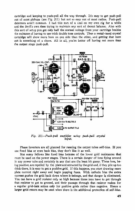
cartridge and keeping to push-pull all the way through. It's easy to get push-putl out of most pickups (see Fig. 311) but not so easy out of most radios. Push-pull detectors aren't common. I had this sort of a deal on my own rig for a while and the devil's own time trying to maintain any sort of decent balance. Also with this sort of setup you get only half the normal voltage from your cartridge besides the nuisance of having to use trick double tone controls. Then a metal-cased crystal cartridge will show more hum on one side than the other, and getting that hum out is something of a chore. All in all, you're better off having not more than the output stage push-pull.
-
,I
6.3V1A TO OUTPUT FILS
Fig. 311-Push-pull amplifier using push-pull crystal input.
Phase inverters are all planned for running the output tubes self-bias. If you use fixed bias or eyen back bias, they don't like it as well.
Not many fellows like fixed bias because of the lower grid resistances that must be used on the power stages. There is a certain danger of ions flying around in any power tube and certainly in any that are the least bit gassy. These ions, being positive, are repelled by the plate and attracted by the grid and, if they pile up too thick there, it is easy to get a positive grid. If this happens, you start drawing more plate current right away and begin popping fuses. With cathode bias the extra current pushes the grid back down where it belongs, and that danger is eliminated. You can have a grid resistor only so high because those ions have to get through that resistor to get to ground, and their passage through that resistor makes for a regu1ar grid-leak action only for positive grids rather than negative. Hence a larger grid return may be used when there is the additional protection of self-bias.
49

RCA's handbook says uot over 50,000 ohms in the grid for fixed-bias 2A3's although it allows 500,000 ohms with self-bias. Sylvania's handbook limits the grid return even more and says you mustn't use more than 10,000 ohms between grid and ground with fixed bias. I fudge a little and use 560,000-ohm resistors in the grid circuits with self-bias, and I've never had bad results.
This is sort of fundamental but here's the point: The smaller resistances used in fixed-bias power tube grids will load down the phase inverter plates. If you follow RCA's recommendations and use 50,000 ohms in each grid return, you can get by at less gain. If you have and use Sylvania's book, then your 10,000-ohm grid resistors will cause considerable distortion at any but very low levels in the triode phase inverters. The pentode circuit with the coupled cathodes will be okay but have much lower gain; however, the triodes will distort at a great rate if the load impedance approaches the plate impedance in value. Remember that triodes want a load at least twice their own impedance unless the level is very low.
I have usecl fixed bias in early stages occasionally. There are times when it is easier to have a bias cell than a cathode resistor, and some folks say less noise comes out. As to power tubes, however, I now avoid fixed bias wherever possible. With any kind of a circuit, values like 10,000 ohms (or even 50,000) can suck away a lot of signal.
With back bias (bias taken from the high-voltage return of the power supply) you can use greater values, depending on the bleeder current. With a poorly regulated supply any current increase would make for a larger I-R drop across the resistor in the B-minus line and thus give pretty much the same results as with self-bias. A well-regulated supply will make your back bias behave just like fixed bias. This is slightly less of a nuisance because then there's less likelihood of the bias supply failing and leaving the B-plus on your plates. It also simplifies the matter of fusing.
Remember that with fixed bias you get no benefit at all in class A. It is only in class AB that output power is increased with fixed bias. The increase, by the way, is from 10 watts to 15 watts (handbook values, and for ideal conditions of power supply regulation) and amounts to about 1¼ db, which is just barely noticeable to an ear that is listening for the change.
Fusing an amplifier is simply a precaution and a good one. There's no tuhe or filter capacitor a\·aila',le that can be considered absolutely safe. Any brand at any price will short out once in a w bile. If there is no fuse or protective relay in your amplifier such a short could ruin an amplifier. All builders should fuse their rigs but many of them do not. Those that are fused at all are usually fused only where the a.c. line comes into the chassis. While that isn't ideal, it is better than no fuse at all.
In class-AB circuits I do believe in fusing the B-plus line, and I cousider such fusing essential in fixed-bias circuits. Failure of a bias supply can easily ruin a pair of matched tubes and quite possibly the output transformer as well.
Fuses are admittedly nuisances and relays are expensive, but then so are the components used in building your amplifier and it's a shame to have them go up in smoke. You can protect the circuit with a small fuse or a simple relay. If you use a relay, you can use the coil as part of the filtering circuit in the C-minus line and have the contacts open the B-plus line whenever there is no current from the bias rectifier.
The worst part of this is that your amplifier goes silent when the bias supply
50

goes, and you can't play it again until you've serviced it. Ti1is can be an annoyance. A way out of that is to use a d.p.d.t. relay (see Fig. 312) in a circuit that will switch the tubes from fixed bias to self-bias.
:111 +JOOV
"'--<I----, ~~~ll~NCATHODE BIAS
SIZE OF BLEEDER IN C SUPPLY FILTER SHOULD BE JUST SMAL'. ENOUGH TO ACTIV.a.TE RELAY
Fig. 312-Guard relay for fixed-bias amplifier.
Broadcast stations have a blinker light that shows whenever the signal is too large. When used in a home outfit, this is a handy device that keeps people with moderately powered rigs from running too high a level. You can be as Rube Goldberg about this as you want to. Personally I figure if I can't tell distortion by ear, then I don't care whether it's there or not. The light does dress up a rig, though, and is not at all hard to hitch up. You can do this by using a thyratron that is biased to trip on a certain voltage (the overload point or just under) and have a small 110-volt pilot lamp in series with the thyratron plate.
If you want to go a step farther and blank out the signal when it is overloaded ( thus demanding it he turned down), you can put a voltage regulator tube of the correct voltage across the plates. Then all will be serene until you exceed the ignition point and wham! - no signal out of the speaker until the level drops below that point. The sound will be so bad you'll be compelled to turn it clown in self-defense. These tubes come in a variety of voltages and, if you can't Anet what you want among them, you can stack up a series of several small neon bulbs. Their drop is about 60 volts each.
Every once in a while some HiFi fan writes or talks to me about directcoupled amplifiers. A lot of people seem to believe they are marvelous. I think they are very nice. A true and honest direct-coupled job will go right down to d.c. and, when you have to amplify d.c., nothing else does quite so well. And a d.c. amplifier is a tough job to engineer and build and adjust.
During the war we had occasion to build an amplifier that was flat from ½ cycle to 1 megacycle and that was a job, but it would have been much, much harder to have it flat right down to d.c. D.c. ampliAers in general (and I mean to amplify zero cycles) are unstable as can be. Every time a piece falls off the
51

cathode (about every 10 seconds or so), the level and gain change. These amplifiers are also very expensive.
One firm has plugged hard at some Loftin-White direct-coupled amplifiers for ordinary home listening. These are not d.c. amplifiers in the strict sense. They will not amplify zero cycles. They aren't bad as amplifiers go, but I could never see much point in the direct coupling.
After all reactance isn't a bogey man to frighten you. There's nothing esoteric about it. Capacitors have their faults, but they aren't as bad as all that. You can get good bass response right down to the bottom of your hearing ability with resistance-capacitance coupling. Since grids are tied directly to plates in these direct-coupled jobs, the second cathode has to be pushed way up in the air. Then the second plate has to be pushed up even farther to attract electrons from that cathode. You end up with a terrific amount of plate voltage required, and for what? Neither output transformers nor speakers work really well on d.c. Come to think of it, I don't think people can listen to d.c. I
Any time you really have to have a d.c. amplifier though, here's a trick you might keep in mind: use neon bulbs or voltage regulator tubes from one plate to the next grid. This will drop plate voltage so that the second cathode won't have to be operating some 100 or so volts above ground. A light bleeder from grid to ground will keep the bulbs lit and they will maintain a pretty steady voltage drop across them so long as they are lit. You can amplify zero cycles with this stunt and still save a lot of voltage. It's about all you will save, though, because, as mentioned before, d.c. amplifiers are tricky things, and such items as broad-band linearity and stability are well-nigh impossible to achieve when you want your response band to go right down to zero.
52

Chapter 4
Amplifier Design
THERE seems to be a good deal of misunderstanding about just what inverse feedback is and what it does and how it does it. Also about how to apply it. It doesn't have to be strictly a cut-and-try affair unless you choose to make it so.
Inverse Feedback
Inverse feedback covers up for a lot of very careless design work in amplifiers in the same way that putty and paint hide careless carpentry. The analogy isn't too bad either, for while putty and paint are considered necessary for nearly every type of building work, careless workmanship makes for a lot more trouble for the putty and paint men.
It works the same way in audio. Sure, you can cover up a lot of sloppy work by putting plenty of feedback around parts of your circuit, but it's considerably easier to make your circuit as good as possible and then apply feedback. The fantastic yarns about having to go to great lengths in order to run a feedback loop indicate, in most cases, that improper attention was paid to circuit constants. Phases can do funny things to feedback loops and once you let them start winding around each other you're apt to get into trouble.
Feedback reduces distortion, broadens the frequency band, makes circuits more stable and more linear, lets you change the effective output impedance, and a lot of other things. It can make a crummy amplifier sound just peachy. But it shouldn't. It should make a good amplifier sound better.
Most of you have undoubtedly seen that classical explanation of feedback. You're usually presented with a block diagram of an amplifier with two leads labeled ~ coming out. That symbol is only beta. a Greek letter B. High-flown engineers and physicists toss Greek letters around with complete abandon, and the reason why they do it is probably the same reason why doctors write their prescriptions in Latin - so the general public won't know quite what they mean and maybe become confused. If they are confused, then they'll think doctors and druggists arc smart and important and on a higher plane than ordinary folk. ~faybe engineers and physicists cherish that same hope concerning the laity of radio and sound men, so they are very glib about things like Greek letters and j and partial derivatives.
Feedback isn't so tough. Take a part of the output voltage and feed it back into the input again and let it go around once more. If the feedback is positive, it
53

will be regenerative and the amplifier will oscillate if the amount fed back is large enough. If the feedback is negative (or inverse or reverse), the circuit will be degenerative and the gain will be reduced. Let's look at Fig. 401. As the gain is reduced, so is the distortion. So is the output impedance. The drawing shows a crazy sort of distortion but one that demonstrates just why the result is cleaner.
Many fellows refer to lOo/o feedback and 25o/o percent feedback, and I've never been able to figure out what they mean by it. I've tried to nail them down but they always stall and manage to evade the issue. I suspect they don't understand the subject and are just repeating what they've heard others say and the others didn't understand it either.
/"\. /'\ /'\ J\TVV
INPUT
FEEDBACK VOLTAGE WITH DISTORTIONOUT OF PHASE
'\ /"\. (\ C\ vvv
_6 /\ (' v~ OUTPUT WITH DISTORTION
t
INVERSE FEEDBACK VOLTAGE RESULTANT WAVE WITH REDUCED DISTORTION
I\ I\ r \TV
WITH GREATER INPUT VOLTAGE-OUTPUT SAME AS BEFORE BUT DISTORTION JS LESS
Fig. 401-Eff ect of inverse feedback on distortion.
To my way of thinking, the amount of feedback can best be described by the amount it reduces the gain. This can be as a factor or as db. If you have 20 db of feedback, you are reducing your gain by a factor of 10. This reduces the distortion ( within the feedback loop) to one-tenth of its former value. You might he feeding back lOo/o of your output voltage to do this, or 1 o/o or 52½%, depending on where you take off the voltage and how far back in the circuit you go before you re-insert it. To bring your output up to where it was before, you have to supply ten times the signal voltage. Assume we have an amplifier without feedback. The amplification A is equal to the output voltage E divided by the input voltage e.
E A = -. Now let's say we take some of the output voltage BE and feed it back
e to the input in such a way as to reduce the gain. Our amplification will now be
E ---. e-BE
54
We can call this new amount of amplification A' to differentiate it from A.

Let us compare our two gains: E
A e E e-BE e-BE e BE ------ - -- x----------
A' E e E e e e
e-BE A E
- = 1 - B -- = 1 - BA. A' C
Not so tough, is it? It means simply that the gain reduction factor equals 1 minus the percentage fed back times the amplification without feedback. Note that the percentage means nothing unless you also specify the gain without feedback. That gain is not the gain of the whole amplifier, by the way; it is the gain of that section of the amplifier that you are going to run your feedback loop around. It can be the gain of a single tube if all you're planning to do is leave off a bias capacitor. It can be the voltage gain from a driver cathode to the voice coil if that's to be the extent of the loop,
That little amount, 1 - BA, is what you use to figure how much voltage to feed back to get a certain effect. That's the same amount you reduce your distortion, too.
Let's figure it out with a practical example. Say we have a little phonograph amplifier we want to clean up with feedback. It has a single 6V6 output and a cheap little output transformer. It sounds poor, but has a lot more gain than we really need.
The first thing to do is figure the actual voltages - peak voltages - at the different spots. Since the load is right and voltages are as recommended, we find out from the handbook it puts out 5 watts with 8% distortion. The transformer is probably about 80% efficient, so we multiply 5 by 0.8 and get 4 watts actually into the speaker. Since it's an 8-ohm speaker, we can get the voltage there by using
E2 ohm's law: 4 watts equals the voltage squared divided by 8. 4 = --.
8 E2 then equals 32, and E equals about 5.7 volts r.m.s. or 8 volts peak. We write
this peak a.c. voltage right on the diagram. See Fig. 402. This vGltage is im-
Fig. 40Z-Bea.m power amplifier with inverse feedback.
55

portant since we will run our feedback from the voice coil itself and thus cut down the distortion in the transformer.
The 6V6 requires 12.S volts to drive it, so we put that down too and turn our attention to the 6SJ7 pentode voltage amplifier. We want to know its gain and we can either measure it or calculate it, depending on whether there is a11 actual amplifier built or not. With these constants the gain of a 6SJ7 will be 100 times or 40 db, and our input to the pentode will be 12.5/100 or 0.125 volt without feedback. The gain then is 8/0.125 or 64 times from the input of the pentode to the speaker itself.
I mentioned we had more gain than we needed. Actually the pickup puts out over a volt, whereas with the volume control wide open only 0.125 volt is neeaed to drive the amplifier to full output. Now we decide how much feedback we can use. If we have a gain reduction factor of 8, then we will need 1 volt at the input. Since we have over a volt, let's make the gai11 reduction factor 10 (a nice round number) and then we'll need 1.25 volts from the pickup, Thus we'll cut down the tube's distortion to 0.8o/o which is small.
A So 10 it will be. Our equation is -- = 1 - BA. Substitute values thus:
A' 10 - 1 -B X 64. 9 = -64B and -B = 9/64 or 0.14, There's the amount of voltage we want to feed back to the input of the pentode: 14o/o. If we had a triode there, we might have to feed back 29.9% to get the same effect. Maybe even 39.9%.
Well, where will we feed back this voltage? If we put it right onto the grid, we'll lower the impedance too much; so let's put it onto the cathode, That way the input impedance is raised slightly. Then we have a fairly low resistance to feed it to and the speaker will not shunt it appreciably because we'll be using a series resistor to make certain that not more than 14% of the output voltage gets there. Since there may be a d.c. voltage on the cathode which may be lowered slightly, we can put a blocking capacitor in the line if necessary.
We can calculate the value of Rr, the feedback 1·esistor, as though it were any other kind of series arm in a voltage divider. The resistor to ground i11 this case is,
560 of course, the bias resistor of 560 ohms. We do it like this: 0.14 = -----
560 + Rr We can solve that by high school algebra like this: 0.14 (560 + Rr) = 560.
481.5 78.5 + 0.14Rt = 560. 0.14 Rt = 560 -78.5 = 481.S. Rt = --- = 3,440
0.14 ohms. If we make our series feedback resistor 3,440 ohms, we'll have 20 db of feedback and reduce the distortion in both tube and transformer by a factor of 10.
The d.c. resistance of the voice coil and transformer secondary now being ahnost zero, if we just put a 3,440-ohm resistor to the· voice coil we'd have as cathode resistance 560 in parallel with 3,440, or about 480 ohms. Not much difference, you might say, but remember we're going to be feeding about a volt an<l a quarter into this grid and that will reduce our bias to just about where we shouldn't. We should put in a blocking capacitor. If we make the resistor the standard value of 3,300 ohms and use a regular bias capacitor, we wouldn't miss the mark by much.
But wait a bit. This speaker we're using has always been poor on the llass end. And we really don't need all this power. Can we boost the bass a bit by using a smaller capacitor in there to block the d.c. Sure we can.
56

Our bass apparently falling off around 100 cycles, that's about where we want to boost Thus we have a total resistance of 3,300 plus 560, or about 4,000 ohms. Therefore, we merely pick a capacitor whose reactance is about 4,000 ohms at 100 cycles. That will be an 0.5-,uf capacitor, and, if possible, we'll use a bathtub.
Now let's hitch it up. The only place we might go wrong is in having positive feedback instead of negative, and that would be because we guessed wrong about the polarity of the output transformer. If we get positive feedback (which we don't want), the amplifier will squeal like a pig. The cure? Simple I Just transpose the leads to the primary of the output transformer, or transpose the leads to the secondary. Let's not get ambitious and transpose both primary and secondary leads, because then we'll be right back where we started.
It sounds fine, much cleaner than it was. The volume control has to be turned up about a.11 the way now for maximum signals, but that's all right. The hum is much lower, the distortion no longer bothersome, highs come through much clearer, and man alive, listen to that bull-fiddle in there.
In fact there's a bit too much bass for some pieces. Th~ pickup lacks bass but voices sound a bit boomy, and even distorted, with all those lows. We notice the bass overloads rather tC'lo easily.
That's not hard to cure. We put the bias capacitor in there on a switch so we can have bass whenever the program lacks it. With that bass boost switch it sounds pretty good. Now if we only had a better speaker ••.
You see how it goes? It isn't tough at all. This voltage feedback business will improve any amplifier that doesn't have it. A simple little circuit has lowered the effective output impedance and the distortion by a factor of 10, broadened the band, boosted the bass end, and made the whole amplifier more stable and more linear.
You might well ask: "Is that all there is to it?" Not quite, but almost. There are things to watch out for. Notice we ran our loop around just two tubes and a transformer. Practically never do we run into squeals with a short loop like that. If you try to include three tubes, you can - if you try hard - make it oscillate.
The phase shifts are what give trouble. There are such shifts in all transformers and R-C circuits. If they stack up their shifts enough to give 180 ciegrees of rotation where you have a gain of over 1, then it will sing. If you have interstage as well as output transformers in the loop, you might not be able to get a full 20 db of feedback. The edges of the band are the tricky spots - phase shifts start winding up at the tops and bottoms of the pass-band.
I have run feedback around five tubes and two transformers, running about 24 db. I was careful not to have my high cutoffs and low cutoffs coming at the same spots on the curve for each tube. The required high end was 12 kc, so the first stage was cut off at 12 kc, the second at 15 kc, the third at 18 kc, the fourth at 22 kc, and the fifth at 14 kc. The transformers selected cut off at 16 kc and 20 kc. In other words, I juggled my cutoffs so that the total phase shift did not reach 180 degrees until way past the top frequency. There was still some oscillation around 30 kc which I took out by loading down the transformers a bit more. It was tricky. Ordinarily I do not run loops for more than three stages and preferably only two.
In general, you will have no trouble running feedback around two or even three stages. Of course you will not try to run a loop around a volume or tone control. Any control inside the loop is bad business for obvious reasons.
This voltage feedback is so called because the feedback signal is proportional
57

to the output voltage. Remember that impedance equals the change in voltage divided by the change in current, and you'll see that voltage feedback tends to lower the apparent source impedance, This makes for a lower load with which to damp a speaker. There are some people who claim this can be carried too far. I have not found it that way.
Another type of feedback in which the signal fed back is proportional to the current through the load, is called, appropriately enough, current feedback. This tends to make the current change less and so raises the effective source impedance.
For feeding a reactive load (such as a speaker), voltage feedback is generally preferred, because of the lower impedance damping the speaker and also because voltage feedl:ack tends to improve the bass a bit more than the treble. Current feedback tends to push the high cutoff farther up the scale than it pushes the low cutoff down. This difference is slight, since both ends are extended with both kinds of feedback.
Current feedback can be calculated exactly the same way that we did that one case of voltage feedback, but there is another way of doing it. This is simply to insert a feedback voltage and then calculate what inserting it does.
As an example of current feedback let's try that system in a very popular form : let's just leave a cathode bypass off an ordinary amplifier tube and see what it does. In Fig. 403, instead of applying a feedback voltage to the tube directly we just let the tube develop its own degeneration.
As set up here we'd have a gain of 100 if a cathode bypass were used. One volt in would give 100 volts out. That 100 volts would be developed across the total load between cathode and plate. Unbypassing the cathode increases the load from 120,000 to 120,560 ohms, and 560/120,560 of the output signal will now appear across the cathode resistor. Since both plate and cathode work against ground, the signal now appearing across that cathode resistor will be such as to buck against the input voltage of 1 volt. We can easily calculate exactly what the amount is:
560 100 X ----- = 0.46 volt. The voltage now appearing between cathode and
120,560 grid is 1 - 0.46 or 0.54 volt. The tube amplifies that voltage because that's all it sees. It doesn't know you are still feeding 1 volt to it. The output will now be 54 volts and the gain will be 54 times instead of 100 times. The factor is close to 2, and the distortion inherent in the tube will be halved.
There's nothing tough about any of this stuff. It isn't even tricky. And above all it isn't mysterious. There was a rule of thumb popular 'way hack, that chopping the cathode bias bypass off a pentode cut the gain in half. And another that cutting out a screen bypass reduced gain to a tenth and that the load resistance should be twice the plate resistance of a triode and the following grid resistance should he twice the load resistance. And that decoupling resistors should be onefifth of the load resistance and that daisies won't tell. There's a good deal of truth in these old wives' tales, and there's generally a reason for most of the empirical rules of thumb that exist in the radioman's talk.
Of course a triode's amplification won't be halved when you unbypass the cathode resistor. A 6JS's gain will drop from 14 to 10, but you can figure it exactly the same way. The tube will then be more linear and will handle a larger voltage without changing the wave shape.
Feedback will also flatten out any little bumps and dips. When the signal is less, there is less feedback, so the gain is cut less. For this reason the band is widened.
58

If you are unmathematical and floored by all this, you can still run feedback in a cut-and-try way. I did the first few times I ran it at all. It's about all that can be done when you have a poor output transformer and don't know just where it will limit and haven't the facilities to measure it. Simply put a potentiometer across the output (make its value high enough that you don't shunt the speaker) and feed back your voltage from the center arm of the potentiometer. Then you can crank up and down with ease and determine the point where it tends to oscillate.
This point, if too close, can often be pushed back by a judicious amount of fooling around with coupling capacitors, from signal to ground at various points, here and there. Each time you clip in a capacitor see how far you can swing the knob.
I prefer feeding the signal back to a cathode rather than to a grid. It works a lot better that way. At times when you insist on a grounded cathode you can also feed back to a screen. It's best, in my opinion, to confine the feedback loop to two stages. If you want feedback over more than two stages, there's nothing to prevent having two feedback loops. One can run around the transformer, output, and driver, and then another circle your preamplifier tubes.
Fig. 403-Ouc of the easiest methods of obtaining negative feedbacl~ is simply to remove the cathode bypass capacitor. In this way the tube develops its own out-of-phase or degenerative feedback. This type of feed-
bacll is termed current feedbacl~.
,Of
IME
...
Running feedback around preamplifier tubes works the same way, but it isn't often done because it isn't often needed. The signal is usually small enough there so that the distortion is low and the linearity high.
As you have seen in that 6V6 job, feedback is very useful for bass or treble boosting. It can be used very easily. Capacitance in the line cuts down the lows so the low notes aren't degenerated as much. Capacitance to ground will cut down on the highs in the feedback line, and therefore boost the highs in the output.
You have to be careful with this though. If you want to boost highs this way, don't do it with the output stage in the loop. That's a good reason for a feedback loop around the preamplifier tubes, The reason is this : If you lose your feedback for high notes, you also do not cut down on your distortion for those frequericies. Since the high distortion is distressing without feedback in the output stage (especially with beam tubes or pentodes), better do your high boosting elsewhere.
The books say you get into trouble boosting lows that way too, although I haven•t found it so. I've often bumped up the lows that way and never suffered for it. It should be done, of course, only to equalize and not to boost unless you have loads of J?Ower. You can see that a 6-db boost at 50 cycles (which really isn't much boost) demands four times as much power. Thus, if you like 4 watts on the peaks at 1,000 cycles, you'd need 16 watts on the peaks at 50 cycles.
59

If you like bass, don't try to economize on a speaker baffle with the idea you'll make it up electrically unless you are using tremendous tubes. Even then it's bad, because to drive an inefficiently baffled speaker hard in the bass end you would have to swing the cone so far your harmonic content would go way up,
IN
~,1--..... ---1, ,OZ
IN
VARIABLE BIAS a
VARIABLE DRIVE b
VARIABLE BIAS AND DRIVE C
Bt
Bt
Fig. 404-Arrangements for balancing output tub,es.
I've already mentioned my preference for low-mu triodes for output tubes. Of all the low-mu triodes I prefer the 6ASG. It is like the 2A3, 6A3, and 6B4G except that it has a heater-cathode and therefore poses less of a hum problem. That is no reason for not balancing output tubes in push-pull circuits. With the filament-type tubes it is necessary to balance to get rid of the hum, but it is also desirable with the heater-type tubes.
Fig. 404 depicts some of the standard methods of balancing output tubes. In the illustration shown at the top left, any unbalance between the two 6A5G's can be compensated by adjustment of the bias potentiometer. Output tubes can also be balanced by varying the excitation voltage applied to the control grids, as shown in Fig. 404-b. The final method of achieving balanced output tubes, illustrated in Fig. 404-c, is simply a combination of the first two methods. In this last instance, balance is accomplished by simultaneous adjustment of the bias and excitation voltage to the control grids of the two push-pull output tubes.
There are all sorts of complicated circuits for telling when tubes are in perfect balance, but the easiest probably is this: Simply short the two output plates together and adjust the balancing knob until you get no output. A reader of some of my articles sent that in and I almost beat my head against the wall for not thinking of it myself. It works fine.
Just because the 6A5G has a heater cathode, don't think you can get by without an extra filament winding. The cathode is tied to the center of the heater and that means you'll have your 6.3-volt filament line some 50 volts up in the air. You can get by with it (some have for quite a while), but you're just asking your 6SJ7's to short their cathodes to their heaters.
60

I strongly recommend the use of glass tubes in the output stages, as the vacuums are better and they last longer. For input stages I like the metal tubes in spite of their shorter life because they carry their own shields along with them. Turtle tubes.
Rp, Gm, p., and Stuff When it comes to voltage amplifiers, you have a fairly easy time of it. A lot of
very smart men have run curves and plotted results and run analyses of practically every aspect imaginable. There are, however, certain things to watch out for.
A lot of fellows have an unfortunate attitude toward the curves in the handbooks. They seem to mentally pull down a curtain when they see a curve and their attitude is: "This stuff is too hard for me; I know I won't be able to understand it." Let's explode some of that right now. A good deal of what these boys
c5 Ep object to is the expression for plate resistance: Rp = ----. They see those
6lp things that look like 6's backward and they say mentally: "That's all, brother, that's all."
Those backward sixes are nothing but a short way to say : a small change of-. The expression merely means that plate resistance is just the ratio of how much the plate voltage changes when you change the plate current a little bit - or
dEP vice versa. Some writers try not to seem mysterious, so they say RP = ---,
dl which makes physicists shudder and which really doesn't help any because nowh!re do they say what d is. The expressions for amplification factor and transconductance are the same way, and, generally, our boys remember vaguely from somewhere that amplification factor is equal to the plate resistance times the transconductance. That confuses them farther because, when they look up a tube where data is given on all three terms, it doesn't seem to multiply out.
Let's straighten things out a bit. The curves in the handbook aren't mysterious in any way. They simply apply voltages (d.c.) to a tube and read the currents as they change these voltages. It's all a d.c. affair. Let's pick up a tube manual and look at the curves for a triode amplifier, say a 6J5. Notice all they have to do to run those curves is put some bias on a grid and then vary the plate voltage. They keep track of plate voltage and they read the plate current passing through the tube. Then they pick another bias and try again. When they get through, they have a family of curves. The term "plate resistance" is nothing more than how those lines slope. The flatter the curve (the less the slope) the higher is the plate resistance.
You can see plainly that the plate resistance is not constant. The lines do curve, more with some bias voltages than others. Plate resistance, then, is a variable. So is the amplification factor, and so is the transconductance. All three are variable, and all wind around each other a bit. They are just terms to express how grid voltage, plate voltage, and plate current behave in relation to each other. The mu of a tube-the amplification factor-is just a measure of how the plate voltage changes when a small change is made in the grid voltage. Transconductance
MP is expressed as Gm = ----,. which is read as delta Ip over delta Eg. This is
~Eg
61

an engineer's concession to those who might resent the backward sixes. It's a poor sort of concession, too, as those little triangles are nearly as frightening to one who hasn't run into them before. Simply disregard all such and consider these symbols as meaning "a small change of."
The curves in the tube books are handy. By consulting them we can predict just how much amplification we can get from a certain tube in a certain setup. The curves are d.c. affairs, but don't worry about that. After all a.c. is nothing but d.c. that changes back and forth in a rather monotonous manner.
TO VARIABLE DC VOLTAGE
B+
B-
Fig. 405-The basic circuit for a triode amplifier is shown in the illustration at the left. RL represents the plate load resistor. The battery indicates any convenient power
supply.
In Fig. 405 we've set up a 6J5 as a simple amplifier. Just now we won't say what values of plate resistance or what-have-you will be used, Just say there is a load 011 the tube. Consider this: We put a high positive voltage (through some resistance) onto the tube's plate, and we ground the cathode (let's worry about the bias later). Some direct current will flow.
The current flew will cause an I-R drop across the resistor, and the rest of the supply voltage will be on the plate itself. Just what the drop is we don't care right now, but we do know that we can change it some by applying a d.c. voltage to the grid of the tube. If we make the grid positive, more current will flow through the tube and the plate resistor, and the 1-R drop in the plate resistor will be larger. That means our plate voltage is going to go down. Conversely if the grid is made more negative, there will be less current flow through the series circuit of tube and resistor and the lower 1-R drop will make the plate voltage increase and become closer to the supply voltage.
There are two natural limits for this behavior: (1) Where the grid is so negative that there is no current flowing, therefore no 1-R drop in the plate resistor, and the full supply voltage is on the plate; and (2) so much current flows that the plate voltage falls to zero - all the voltage is across the plate resistor. Never mind for the moment about these being impossible conditions; these are extremes - first, where plate has full voltage and passes no current and, second, where it passes full current and has no voltage.
Now let's decide on some values. Say the supply voltage is 280 and we pick the load of 56,000 ohms for a plate resistor. Now our extremes are: (1) 280 volts and Oma and (2) 0 volt and 280/56,000 or 5 ma.
In Fig. 406 we have a curve family for a 6}5. Notice the line drawn between our two extremes. This is a load line. Since the load is resistive, the line is straight and it touches the curves from a bias of O down almost to a bias of -16. With a bias of -6 volts the load line crosses the curve where the plate voltage is 149 and the current is 2.4 ma. That means just what you'd think: with a load of 56,000 ohms and a supply voltage of 280 and a bias of -6 volts, you'd have 2.4 ma flowing and a plate voltage of 149. There will be 280 - 149, or 131 volts, lost across the resistor.
Now let's cut the bias to -2 volts. That shows a plate current of 3.5 ma
62

and a plate voltage of 81. At a bias of -8 we have 180 volts on the plate and a current of 1.8 ma. At --4 volts bias we have 116 volts on the plate and a current of almost 3 ma.
Now let's shift our bias back and forth between --4 and -8 volts. We c-an do it fast or slow and keep it up as long as our wrist holds out. As long as we keep it up, we will swing the plate voltage from 116 to 180 and back.
If our wrist gets tired from twisting the knob to shove the bias back and forth like that, we can put a permanent swing on the grid with an oscillator, and to keep the swing between --4 and -8 we can put a battery bias of -6 on the grid at the same time.
Well, what do you know I We've got a.c. on the grid now I An a.c. that goes up 2 volts and then down 2 volts, a total peak-to-peak swing of 4 volts. The plate is still swinging from 116 to 180, too. That's a peak-to-peak swing of 64 volts. And 64/4 shows we now have a gain of 16 times I
13
12
I
10
9
PLATEMA 7
6
5
4
3
2
MIIALOAD
7" u IOOll!L 'O / -1-1 -,
'
E,,OJ
I I
I I I I
J J I I
I I ~, J / ----
' ~ j'-,, ,
6J5 6.3V ON HEATER
-2 _,. -8
I ' J I I I
f-8
J J J -1111
I I I I -12
' I I I I I -14
I I I I I/
' ' ) 1-Y .J.. I / / "' ) -_,/ ..... .,L.. / V
, ... I I/ ... v _,,,, ,,,, ., _)/ ~ ,,,
0 ~~oo~oo~~~~~w~mm~~~~* PLATE VOLTAGE-TUBE CHARACTERISTIC CURVE
Fig. 406-Graph for obtaining the load line of a 615.
Wait though. Our quiescent point (or starting point, if you like) is -6 volts on the grid and 149 on the plate. Our grid swing is 2 up and 2 down, but the plate swing is 31 up and 33 down. Distortion. How come? Inherent in the tube family. See how the tines are farther apart at the low bias and closer together toward the right? Distortion is 2 volts out of an average of 32 or approximately 6%,
Let's shift our operating point to -2 volts. Now the grid swing is from O to --4 and the plate swing is from 116 to 49, making a total swing of 67 volts. Again our swing is distorted : 35 volts up and 32 volts down.
Now let's change loads. Let's shift to 100,000 ohms and draw a new line. We will keep the -2-volt bias and still swing 2 volts up and down. Our plate now goes up 35 volts and down 34 volts. Much better.
Now we can use battery bias if we wish, but it's cheaper to use a cathode resistor. At the quiescent point with 100,000 ohms in the plate circuit the current
63
is 2.1 ma. We want 2 volts of bias, so ohm's law gives us 2/2.1 or 1,000 ohms. That will be a whisker more than 2 volts, which is okay. We lose 2 volts from our plate supply by this; so to be really rigorous we should increase our supply voltage to 282 volts.
Now this 1,000 ohms in the cathode circuit is also part of the load on• the plate, and a signal will be on it unless we shunt it out. A capacitor to ground will hold a charge from one half cycle to the next (if it's the right size) and will make the cathode effectively at ground potential as far as a.c. goes. The size of the cathode bypass must be such that its reactance is low compared to 1,000 ohms at the lowest frequency we intend to amplify. If 100 cycles is the lowest we care about, a IO-microfarad capacitor will shunt that 1,000 ohms down to less than 150 at 100 cycles and to less than that at higher frequencies. A 1-00-microfarad capacitor will shunt it down to 15 ohms at 100 cycles and to 150 ohms at 10 cycles. How do we judge?
One way is to compute just how much signal we will lose in varying conditions. Without any cathode bypass the resistance will be 1,000 ohms and the
1,000 signal will be ----- times the 35 volts of a.c. (peak) on the plate, or about
101,000 0.34 volt. That much will be lost from the grid excitation of 2 volts and so the output will be reduced. To get the same output we would have to increase the grid-to-ground swing.
If we have a capacitor in there that shunts the cathode down to 150 ohms from 150
ground, the cathode signal will amount to 35 X ----- or about 0.05 volt, 100,150
and the grid signal would have to be increased to only 2.05 to get the same output. If the bias capacitor is large enough so that it shunts the impedance down to
15 15 ohms, we would then have 35 X
want to. See Fig. 407.
----- or 0.005 volt. Go as far as you 100,015
Of course we have just considered the plate swing-a varying d.c. voltagebut now let's plan on feeding the signal to another grid. That calls for an isolating capacitor, and then the following grid will have to be nailed down to ground with another resistor. The combination of coupling capacitor (.01) and grid return of the next stage (1 meg) will shunt our load resistor to a degree. For most of the band the combined (dynamic) load will be 100,000 in paraltel with 1 megohm, or about 90,000 ohms. We can either redraw our load line now or we can increase our plate resistor to 111,000 ohms. In actual practice I do neither but just calculate for a slighter smaller gain.
The business of voltage amplifier design is simplified by the resistance-coupled amplifier charts in the tube handbooks. Here you'll find actual figures for gain and maximum output for a great variety of supply voltages and resistance values. They are all worked out for you. To the best of my knowledge they are absolutely reliable. They are great time savers.
Some of these tables are a good deal more elaborate than others. They offer a choice of supply voltages, load resistances, and what not and give the values of the maximum output voltage and the gain to be expected. There are some things to think about when you use them.
Bear in mind that distortion is not tabulated in many of these charts (it is in Sylvania's), and do not make the mistake of assuming that these values are for
64

undistorted outputs. In the example we worked over we saw that distortion can ht figured from the curves. The spacing between bias curves shows very clearly the amount of distortion, and judicious choice of bias, load impedance, and other items can minimize this. A glance at the curves for the 6]7 and 6SJ7 will show you that the 6J7 has less inherent distortion. The curves for any tube will allow you to pick at sight a bias for least second harmonic.
Instead of plate resistance curves you might prefer to use amplification factor curves for some tubes which are shown in several handbooks. Or, if you like, you can replot the data into that form. Or you can pick transconductance curves where the lines show how different grid voltages (along the base line) affect the plate current ( vertically along the side) for each of several different plate voltages. The latter type of curve is very nice and easy to work, and is shown often in textbooks. A quick glance determines the linearity and, hence, the optimum bias.
Fig. 407-A complete circuit for a resistance-coupled triode amplifier is shown in the circuit at the right. The value of cathode bypass capacitance can be calculated from the data given
in the text.
+282V
OUT IMEG
For a general rule of thumb for use with the amplifier charts you can say that, if the output shows a maximum of x volts, you can quite safely have a clean 75% of x. It is obvious that the larger the plate voltage the farther you can swing without running into harmonics; if you must have more volts than the charts show, you can simply increase the supply voltage.
Feedback will also clean it up quite a bit, as you know, and is the cheapest way to get large, clean signals for special applications. I think feedback should not be used to make a bad amplifier sound good. It's admittedly done quite often, but I prefer to build a good amplifier and then apply feedback to make it even better. Feedback can be and is used to cover up a lot of sloppy design work.
Several commercial firms go to the other extreme. They plug the fact that their amplifiers have inverse feedback and are therefore better than other jobs. Checking the diagrams of these often shows that their amount of feedback is so slight it wouldn't make you blink if you it all in your eye. These amplifiers, however, can easily have more feedback put around them, and they operate much better though at less gain.
Commercial firms have other practices that seem like the ragged edge of truth. They speak of 5% over-all distortion but mean only the distortion arising in the output stage and that ideal with matched tubes in a zero-impedance power supply. They fudge a little on the matter of gain. What they claim is 125 db often measures as 118 or so. They say 1-db variation over a range of 50 to 10,000 cycles but mean 2 db really: they figure on drawing a zero line arbitrarily and
65
then saying there is a maximum deviation from this line of 1 db. Even at that they often chisel a bit. They also sometimes speak of the glorious fidelity of their volume expander !
There has never yet been a commercial volume expander that doesn't put in a lot more distortion than it's worth. I've known several people with outfits who got as good expansion as can be had in the average setup - and those folks keep their expanders turned off.
At first glance this business of volume expansion sounds fine, but, when you stop to think about it a while, you realize it can't be done. Any amount of time delay at all will ruin it, and you've got to have some time delay to the expansion unless you nm a separate enhancing channel.
The Hollywood studios go in for this separate enhancing stuff occasionally and - by dint of a terrific amount of labor and trouble and a whale of an amplifier -do manage to get some pretty fair expansion. It just doesn't work out for the home outfit though. When Disney studios put out "Fantasia," the sound equipment for each road-show unit cost in the neighborhood of $30,000. They had five sound channels and an enhancing channel for the sound. It sounded great, but it sure isn't practical for the average home listener.
All a volume expander is - to the home listener - is a means of regulating the gain of an amplifier with a signal derived from the music itself. This can be done conveniently in several ways. A two-grid tube like the 6L7 will do it or an ordinary remote cutoff tube can manage it if you feed the controlling voltage to the cathode and the signal to the grid. Just rectify the signal and use the resulting d.c. to alter the bias so as to give greater gain. Sounds fine, doesn't it?
But - when you rectify a signal, you filter the d.c. enough to smooth it out and the time constants of the filter make for a certain time delay before the d.c. is up to just the right amount. By the time the expander manages to get this proper d.c., a good part of the signal has gone through without expansion and the result is blah-BLAH. You can vary the time delay considerably by choosing filter constants with care, but it is doubtful whether you can ever get it small enough so you won't he conscious of it and annoyed by it.
It was back around 1936 or so that the whole country became acutely volumeexpander conscious. Everybody began talking about them, but they all stopped by 1937. In like a lion and out like a mouse.
If you still want to make one and see for yourself, go ahead. There is a very nice one (as volume expanders go) in the back of the little R.C.A. tube manual. Any time you operate on a curved portion of the characteristic, you know, you'll get intermodulation; so don't be surprised if you get it here. It won't be large, however, compared to the other faults with it. Fortunately, large voltage swings are rarely needed in amplifiers. Class-A 2A3's require only 45 volts to drive them. Beam tubes require even less. It's only for special deals that you have to cudgel your brains about how to get enough voltage swing,
AB-Triode Amplifier There are some on the ragged edge. A man who wants a pair of triodes in
class AB needs approximately 67 volts of drive, and, since a small amount of grid current exists, this had better be from a low-impedance source. That means either a pair of low RP triodes as drivers or a power driving stage or a pair of cathode followers.
A pair of 6J5's have a nice low plate resistance, but it's hard to get a clean 67
66

volts without at least 400 volts of supply voltage. You can, of course, use another pair of 2A3's to drive them and in that case you'd have to use the same curves as we did on that example. Pick a fairly high load resistance and operate them in the low-current region. Your gain won't be much - about 2 times - but it's a way to do.
We're rather partial to the circuit shown in Fig. 408. There we have a
* 4V OR LESS DEPENDING ON SETTING OF OUTPUT POT
* .36V HERE FOR -FULL OUTPUT
a PHONO PRE·AMPL b XTAL MIKE AMPL C HIGHER FIDELITY MIKE AMPL
Fig. 40&-CJass-AB fixed-bias amplifier. Three difjerent types of input are shown.
cathode follower which has a gain of even less than 1, which means you have to supply around 70 volts to the cathode follower's grids. This can be done with a pair of pentodes since there is no grid current in a cathode follower. The output of the cathode followers being around 350 ohms, large bathtub capacitors and a low grid resistance on the triodes can be used. We can't, however, use the cathode followers themselves in an adaptation of the old standard phase inverter, as their gain is 0.94 times. Their input impedance is as high as their output is low, being R/ (1-A), which makes it, in this case, around 13 megohms, so we can use small coupling capacitors and the load on our pentodes will be very slight.
67

There must be 71 volts at the grids of the cathode followers, or 142 from grid to grid. The 6SJ7's, with these constants, have a gain of 166 times; therefore, we need - without feedback- about 0.86 volt at the top pentode grid.
For safety's sake include a relay to switch the tubes over onto self-bias should the extra rectifier fail. The transformer impedance ratio should be 3,000 ohms to voice coi:. The amplifier output will be normally 16 watts, and in self-bias operation about 10. From this we must subtract the power lost in the output transformer, which runs from 80o/o to 85o/o efficient. Depending on the transformer chosen, you should be able to run up to around 12 db of feedback without any trouble, since there is practically no phase shift in the cathode followers. With a potentiometer across the output you can vary this to suit conditions. It will help linearize the whole works a lot, as well as cut down on distortion.
If you're planning on using this circuit, you should also have a well-regulated power supply because the current varies in any All stage. Just the output stage alone will vary from 80 ma at no signal to about 115 ma on peaks. Since the rest is class A, that's about all the variation, but that's sufficient to let the plate supply dip down from 350 to 250 on peaks. That dip will go right on through the rest of the amplifier and cause distortion of its own, so regulation is really needed here.
Let's assume you can put enough feedback around the transformer and the tubes to make a 4-volt input necessary for full output. This is probably okay for the output of a radio tuner, but there aren't many pickups that can operate directly into it. A good crystal doesn't put out much more than about a 0.5 volt usually. There are a few that sound pretty good that put out more, but most of them can't be counted on for much over 0.5 volt, and a good many even less.
To get a little more gain then, we add another tube. Since we don't need much, we can use another 6J 5. If we don't bypass the cathode to ground, we'll get a gain of around 11 times, which will reduce the amount needed for full output to 4/11 or 0.36 volt. Adding a volume control to our input leaves us about set for a phonograph input.
lf we plan on using a microphone, then, we will need even more gain. For this a pentode should do the trick. If it's one of the high-level crystal mikes, we can get by with a single pentode directly into the phase inverter pentode; and if we have a more expensive mike, we'd better run it into the phonograph input. Since the mike probably will not be used for music I suggest a smaller-than-usual coupling capacitor which will attenuate the bass a bit, as will the input resistor to the tube.
You might wonder a bit at the lack of a bias resistor in the mike amplifier. Extra bias really isn't needed with a mike. Contact bias is plenty there.
Contact bias is what they call that little trick manufacturers of radios have of grounding the cathode of the detector tube and then putting 5 megohms from grid to ground. It works, and that's all that's important in such a case. With all the electrons inside a tube, some of them manage to get onto the grid structure. The only way for them to get off is to go through the grid resistor and their passage makes for a negative voltage on the grid itself. This is the same idea. A 6SJ7 with one-half megohm in the grid circuit will show about -0.6 volt on the grid if you use a vacuum-tube voltmeter to read it with.
This mike amplifier is obviously not a high-quality circuit. This is to fill a job (such as I actually built) of playing music through three speakers in a large room with a single mike by the telephone for paging customers. It was rigged
68

up with a push switch on the mike stand so arranged that no B-plus went to the mike amplifier until the button was pressed. Then the music was cut off until the page girl had finished. The music channel was worked from a large record changer and was fairly wide-band and clean, but the mike channel was strictly for greatest intelligibility.
To use the same sort of a mike and get more fidelity out- as in home recording or some such use - you have to let more bass through and to make the mike put out more bass. The passage of bass notes demands larger coupling and larger bypass capacitors. On that circuit I'd increase the screen bypass to 0.25 µ.f and the coupling capacitor to a 0.02 µ.f. To make the microphone put out more bass put a load of about 5 megohms on it. I wouldn't suggest putting all 5 megohms into the grid-to-ground circuit. Better 2.2 megohms to ground and then a 2.7-megohm series resistor. To get better high notes then reduce the plate and screen resistors to 270 k and 1.2 megohms. To get more linearity I think I'd put about 820 ohms of cathode bias and bypass it with 25 µ.f. It adds up to a lot less gain but a cleaner amplifier.
Microphones vary a lot, but you can count on 10 millivolts (.01 volt) out of a cheap crystal. You can count on about 3 or 4 millivolts out of almost any highimpedance microphone that you're likely to buy unless you're a broadcast station owner.
Frequency Limits This business of designing an amplifier isn't hard, and some folks would say it
isn't designing, but it works out simply. There are only so many things you must keep in mind .
.,. b HI NOTE LOSS a .,. LO NOTE LOSS
m rra EQUIVALENT FOR TREBLE TRANSMISSION•~z EQUIVALENT FOR BASS TRANSMISSION•R-~X
Fig 409-Frequency limitations in simple amplifiers.
You can look up the curves or the tables to find what values to put to your components. Set the high-frequency limits with capacitance to ground and series inductance. Low limits are set by series capacitance and inductance to ground.
One of the serious limiters of low-frequency transmission is the coupling capacitor of an amplifier. See Fig. 409. The capacitance ( C) is in series with
69

the signal and the resistance (R) to ground. It can be represented by a simple C-R voltage divider across any generator.
10° It's the reactance that does it. That value X which is equal to---- ohms
21rfC with C the capacitance in microfarads, f frequency in cycles, and 21r equal to 6.28. Since f is on the bottom side of the line, it follows that X increases as f decreases. This means the capacitor is practically a short (as far as a.c. is concerned) at high frequencies but very much a factor to contend with lower down.
A voltage divider isn't hard to understand. Where X is large enough, the signal divides between R and X, and, when it does, there'll be less across R. The voltage across R is what is passed on to the next tube, and we'll end up wondering where the low notes have gone to.
Figuring the impedance of series capacitance and resistance isn't tough. They don't add arithmetically but they add in quadrature. That is signified by that j in front of the X. Like the backward sixes it isn't mysterious, but a lot of people act as though you have to be a high-powered engineer to understand it.
All that j means is that one term is rotated in phase by 90 degrees from the other. Most radiomen say minus j when they mean capacitance and plus j when they mean inductance, but their significance is the same. Don't worry about the phase angle here because psycho-acoustic men tell us the ear isn't sensitive to phase distortion. All we need concern ourselves with is the magnitude of the impedance when we add them. We get that by adding them in quadrature: the way the sides of a right triangle add up to the hypotenuse. The square of the impedance equals the sum of the squares of the resistance and the reactance. z2 = R2+ x2.
In case you don't care about figuring it that finely, you can say that you'll have reasonable bass response down to the point where the reactance is small compared to the resistance. How small? Well, pick the lowest note you'll want to transmit and make your coupling capacitor of such size that its reactance isn't more than about half of the resistance. It'll be all right. The bass will fall off there, but it won't fall off too much. Of course, each stage you couple will have this same effect. If 1 db is lost in each of the four coupling capacitors at 50 cycles, the total loss will be 4 db.
Don't make your bass response a bit better than you really want it. There are reasons why it's nice to have small coupling capacitors. The larger ones are more expensive, are more likely to leak, and you'll probably have trouble with motorboating.
Just in case you don't know that term: When an amplifier has lots of gain down around the low frequencies and not enough decoupling networks, it will oscillate at a slow rate and go putt-putt-putt-putt like a motorboat.
You can use small capacitors if you'll use large grid resistors, but there's usually a limit to how large they can be. A power stage shouldn't have more than a 560 k, and most voltage amplifiers shouldn't have much over a megohm.
This is referred to by a lot of people as a matter of time constants. Although they often know what they mean, they find difficulty explaining. They mean this: A capacitor will accept a charge and let it leak off at a rate determined by the product of ohms times farads. One megohm and 0.1 ~f will have a constant of 0.1 and that is in seconds. It will take 1/10 second for the charge to leak off through the resistor to a reasonable value. Therefore, they say, a wave that occurs at slower intervals than 1/10 second will allow the capacitor to discharge between
70

occurrences and there will not be a constant voltage drop across the capacitor and, hence, the capacitor wilt not pass it along properly. If you'd like to think of it that way go ahead. It seems easier to call it a simple voltage divider with one of the arms a capacitor.
A few other things also help determine your bass cutoff. There's the matter of the primary inductance of the transformer and that should be as large as you can get it. Then there's the matter of bypassing cathodes and screens. There's also the question of speakers and baffles.
The high notes work the same way, but that may be a little bit tougher to conceive at first. A tube, like any other generator, has a certain internal impedance. There's plate resistance and the load resistance which is effectively in parallel with it as far as a.c. goes. For triodes this is usually low. For pentodes it is high. There is also capacitance. There's some capacitance right across the load resistor itself and there's the internal capacitance of the tube as well as the wiring capacitance, and these are all from the signal (either plate or grid) to ground or - what is heavily bypassed to ground - B-plus.
Consider all the capacitance as one big capacitor to ground and think of the tube's resistance as being in series with the generator. Now you can see we have exactly the same sort of resistance-capacitance voltage divider, only it's the stuff across the capacitor that is passed on. Where the frequency is high enough so that the reactance is small compared to the resistance, we will lose quite a bit of voltage across the resistance and the next tube won't see it. High notes won't come through at all because of the shunt capacitance.
This capacitance is a sum of quite a lot of capacitances, all effectively in parallel. I've already mentioned the wiring capacitance and the internal capacitance of the tube. Fig. 410 is put in to remind you of all these little capacitances. Don't think the internal capacitance is just the matter of the plate-cathode capacitance - that is a mere drop in the bucket.
Fig. 410-The inter-electrode capacitance of a triode is shown in the circitit at the right. The effective capacitance between the grid and cathode is known as
Miller effect.
,----,----..--~B+
I I
;Cpk
' I I
There's a little item known as the Miller effect which complicates matters. This is just the name, of course, of effective grid capacitance. The tube manual gives the grid-to-cathode capacitance and the grid-to-plate capacitance. The gridto-cathode is understandable, but the gain of the tube enters in and is a multiplying factor for the grid-plate stuff.
Now let's take it easy. Capacitance as such doesn't mean a thing except for the charge it will accept and hold. This charge is a function of capacitance times voltage. The capacitance between grid and plate isn't much, but the voltage is greater by the gain (A) of the tube. Therefore, there'll be more of a charge on that capacitance and the effect will be as though you had a capacitance A times as large.
71

This is the famous Miller effect (aren't you glad you stayed?) and can be described as the effective input capacitance of a tube being a function of the gain of that tube. In case you want to figure it, it is simply this: C1 = C1k + C1P
(A+ 1). Take a 6J5 tube. The grid-cathode capacitance is 3.4 µµf and the grid plate
capacitance is 3.4 µµf. Input capacitance of a 6J5 set up for a gain of 14 will then be 3.4 + 3.4 X 15, or 54.4 µµf. Now if that is tied to another 6J5 plate, there will be in addition the 3.6 µµf of the other tube's plate-cathode capacitance and maybe 5 or 10 µµf of wiring capacitance. Add them all up and you have around 65 µµf. Not much when you consider that a plate resistance of around 8,000 ohms is also strapped across that. In other words we have a series 8,000 ohms and a shunt reactance of around 120,000 ohms at 20 kc. That's not going to knock down highs much.
This time let's take a pentode. Since that has a plate resistance of close to 1 meg, obviously we might be in trouble. Let's say it's a 6SJ7 and is set up to have a gain of 100 times. The grid-cathode capacitance is 6 µµ.f and the grid-plate .005 µµf. The input capacitance is then 6 + .005 X 101, which is 6.5 µµ.f. Now add to that 7 µµf for the output of a previous pentode plate and about 10 µµ.f for wiring and odd capacitances, and we have 23.5 µµf. The reactance of 23.5 µµf
reaches a megohm at about 7,000 cycles. Whoa. This is terrible. No high notes. But wait. We have a 100,000-ohm resistor tied from plate to B-plus, and
B-plus is the same as ground and that means the capacitive reactance has to get close to 100,000 ohms before it will have much effect and that won't be till up. around 40 kc or so. We'lt actually notice a falling off of highs before that but not till up past the audio band.
Now you see why designers use both pentodes and low-mu triodes as HiFi voltage amplifiers. Let's look at a high-mu triode, say a 6SF5. The grid-cathode capacitance is 4 µµ.f and- the grid-plate capacitance is 2.4 µµf and it's set up for a gain of 65 times. The total input capacitance is then 4 X 65 + 2.4, or 160 µµf.
Quite a bit. Now if we add 3.5 µ.µf for a previous plate and 10 µµ.f for stray wiring capacitance, there is a total of 173.5 µ.µf across a plate resistance of about 65,000 ohms. That shows a noticeable falling off at 10 kc.
Suppose we haven't another tube in front of it and are trying to run a highimpedance input directly into a 6SF5. If the input is 1 meg and the capacitance 160 µµf, we will start cutting off at about 1,200 cycles. Even Perry Coma's high notes wouldn't come through.
So while high-mu triodes are cheap and give large gains, let us still remember not to use them on inputs that are high impedance. If your source has low impedance, you can get by.
There is a joker to look out for in this. If you run a low-impedance source into a high-impedance potentiometer and then into a high-mu triode, everything is fine so long as the potentiometer is wide open. But when you crank the potentiometer down, you are inserting series resistance which adds right onto your source impedance and then you may start wondering where all the treble has gone to.
A good deal of this Miller effect can be avoided by using a lot of feedback, but you're still beating your head against a wall any way you want to look at it. Save yourself a lot of fuss and trouble by simply using a low-mu triode. Or if you want more gain, use a pentode.
High notes can also be blocked, as you know, by a series inductance just a~
72

easily as by shunt capacitance. However, the only place you'll ever worry about this is most likely the output trans former.
To summarize: Large capacitors pass low notes better; reactances are smaller so there is less lost across couplers and bypasses. Primary inductance ( shunted across the line, you see) should be large for good bass. Conversely good high notes want small shunt capacitances to make for larger reactances to ground and small series inductances such as leakage inductances in the transformers. The sizes of all these reactances are to be compared to the appropriate resistances coupling reactances to coupling resistances, bypass reactance to the impedance to be bypassed, input capacitance to input impedance, etc.
The best way is to set the limits of your band and decide how much loss you can stand here and there. Then balance resistance, and reactances as you go
6SJ7 6SJ7
150 100 50V IOW
2A3
zw
Fig. 411-Single-ended triode amplifier using decoupling filter.
through the circuit. One of the handiest things along this line is a reactance chart: several companies put them out quite reasonably. Keuffel & Esser make up small ones that just fit on a desk slide and that show inductive and capacitive reactances from 10 cycles up to 5,000 kc. You can get them exactly on a slide rule and check the magnitudes on a chart or you can get decent approximations directly off the chart without a slide rule.
Motorboating
Motorboating was mentioned before, but nothing was suggested for getting rid of it. Motorboating is a nuisance and becomes more so rapidly as you extend bass response. It's a form of oscillation and has to he attacked as such.
73

Let's take a simple little 3-tube amplifier such as is shown in Fig. 411, only without the feedback. All three stages are fed by the same B-plus line and, in spite of all the capacitance to ground, there is still a definite impedance there of at least 50 ohms. That 50 ohms will have a certain signal developed across it by the output tube. After all, the tube works against ground; and, while the bulk of the signal voltage will appear across the transformer itself, some also appears across the last filter capacitor. The voltage at the output plate will be about 132 volts (peak) at full output. If the total impedance is 50 plus 2,500, then about 1/50 of 132, or 2¾ volts, will be the amount on the B-plus line.
The driver pentode's plate has a signal that is 180 degrees out of phase with this voltage, and besides it handles about 45 volts or so which is large compared with 2¾ volts. But let's look at the plate signal of the first tube. There our signal is of the same order of magnitude as the signal on the line, and, what's more, the phase of that signal is right for the voltage on the B-plus line to reinforce it. What happens? Right. Just like a pig under a gate.
The answer isn't tough. Just put a decoupling filter somewhere between the first and last tubes, a series resistor to drop the voltage, and a capacitor to ground. How large a capacitor? Aha I Now we are getting to it. If we put in 0.1 µ.f, there would be no squealing any more because at the high frequencies the reactance of the capacitor is small compared to the series resistor and so there would be much attenuation of the signal going back along the line. But at low frequencies the attenuation wouldn't be as much since the capacitive reactance goes up in the bass end. "Putt-putt-putt." Solution? Simply a larger decoupling capacitor.
The more bass response an amplifier has (and the more gain) the more likely it is to putt-putt. There's another solution, too: cut down on the amplifier's bass response. A sad and cruel cure, to many, so the capacitor companies keep making larger and larger filters to use in decoupling networks.
A rule of thumb which does nicely is to use a decoupling resistor of at least one-fifth the value of the plate load and make the capacitor size in microfarads equivalent to the lowest frequency your rig will pass, divided into 1,000. If the plate load is 100,000 ohms, then the series resistor (ahead of it along the B-p!us line) should be 20,000. If the lowest note is 100 cycles, the capacitor should be 10 l'f; or if you want 50 cycles, make it 20 FLf,
This decoupling filter also smooths out the B-plus a bit more and cuts down the hum level nicely. Dual purpose. The rule of thumb is conservative, and, if you stick to it, you will most probably never have trouble. The only time you'll foul up is when you go to extremes and try to run high-gain amplifiers down to 10 cycles or so. The little clinker in that grate is simply that the large electrolytic capacitors are just not that good. Any time you stack up 1,000 µ.f in electrolytics, you can't depend on the reactance being what it ought to be. It should be around 15 ohms at 10 cycles, but it won't be lower than about SO and the R-C voltage division won't act the way you plan. It really pays to be moderate in your demands for low-frequency response.
Tone Controls The whole business of tone controls is largely a matter of these a.c. voltage
dividers. They are simply networks of resistances and reactances set up to favor some frequencies over others. They can be worked out very easily, though they can be tedious if you insist on being too fussy.
The most familiar is the standard high-cut control that most radios come with.
74

This is simply a potentiometer in series with a capacitor set across the line somewhere. It's generally put at the output transformer to limit the load on the amplifier at the same time, but it will work anywhere. It cranks down the highs.
A very similar deal is the low-cut control. This is usually just an extra and smaller coupling capacitor between stages, and the potentiometer simply shunts it out. Then there are so-called boost controls. The bass booster merely chops out middles and highs, while the treble booster cuts down on the middle and low stuff.
Another story is the system of boosting the ends of the band by inverse feedback. We have already discussed that method. It's by far the most complicated and probably the hardest to understand. Realizing that one cuts gain by applying feedback, one can boost certain frequencies by simply chopping out the feedback at those frequencies. To boost the bass end, just put in a series capacitor that will limit the feedback at the bass end. To boost the highs, simply shunt some of the high-frequency feedback to ground. The sizes of the capacitors to be used this way work just like capacitors in amplifying circuits. They are just voltage dividers for a.c. The boosts will become effective where capacitive reactance equals the resistance or impedance involved.
I IN
Fig. 412-L-C tuned tone boosters.
Still another species is the tuned-circuit type, as shown in Fig. 412. Here an inductance and a capacitance are used to give a boost to some particular frequency. The Q of such a circuit should be low enough to give a broad hump and not a sharp spike. Circuits like these are found in pentode plates and triode cathodes.
These circuits were plugged rather heavily a few years ago by the transtormer companies (who wound the chokes), but there's been much less publicity on them lately. There's nothing tough about them. In one such circuit a pentode isn't given much load, resistively, for most of the band, and then, close to the resonant frequency, the impedance starts rising and the tube has a greater load to work into. In the other there is heavy degeneration in the cathode circuit for most of the band, and then, at resonance, the series impedance drops to a low value and those notes are well bypassed so the gain goes up.
Thordarson had a nice tricky deal similar to this, but with potentiometers to insert the chokes into either a cathode for boost or a plate for a cut.
If you want to get super-fancy, you can even dig out Terman's Radio Engineering Handbook and design yourself an m-derived equalizing filter. The design is simple, but winding the chokes comes harder.
75

The big trouble with any of these circuits involving coils is shielding. Coils put out a large field, and shields aren't too effective when you want high gain. The transformer companies use big cases that they say are effective 96-db shields. Maybe so, but they don't give them away. Of course, you could use all toroid coils since they have practically no external fields, but then you really are going to a lot of trouble.
You can beat the manufacturer's prices by winding your own coils, but a shield around a coil changes its inductance and, more important, also its Q quite a bit. If your shielding is less than perfect, you'll pick up hum like mad, and oscillation is by no means unknown.
When you come right down to it, coils aren't worth their cost to the home set builder, especially when it is possible to get almost any kind of curve you want with just resistors and capacitors. Let's get back to the a.c. voltage dividers.
A simple bass booster is shown in Fig. 413a. Or, if you prefer, you can call it a high-and-middle cutter. If the capacitor were shorted, you'd have a simple
R2 attenuator, and the voltage out E 0 would be E1n ------. That's what the
R1 + R2 output is at high frequencies where the capacitor is an effective short. At lower frequencies the reactance increases until the series impedance of R2 and C becomes appreciably larger than R2 alone. The impedance will be Z = (R22 + X2) %,
and that value of Z will show the output signal across it. v""'R=-2=-2-x----,x==--2
If you'd like to compute the transmission, E 0 = ----------V (R1 + R2) 2 + X2
That looks complicated and it certainly is tedious to calculate, but all it takes is
~ IN l. OUT
C
BASS BOOST a
IN
BASS L TREBLE BOOSTER tFORUSEAFTER A TRIODE)
b
Fig. 413 a-b.-Resistance-capitance tone boosters.
some time, and, if you'd like to check, go ahead. The bass rise will become noticeable where the capacitive reactance equals R:i. The bass will rise at a rate of about 5.5 db per octave (theoretically 6 db per octave) until the tapering-off point which occurs where the impedance (r-jx) is about equal to R1, The amount of rise is determined by the ratio of the resistors, and the frequency of the rise is determined by the reactance.
We have a very great attenuation of high notes here. Middle ones, too, but the highs interest us rather a bit more than the middle ones. If we want a corresponding treble boost, all that is needed is to provide a resistor and capacitor combination to isolate the highs from the circuit as is shown in Fig. 413b. Here, you see, the isolating resistor is a potentiometer, thus allowing the capacitor to feed high notes clear over the attenuating circuit or to dump them square into a 21-to-1 loss.
76

For my taste I'll pick about a 20-to-1 ratio and make R1 about 100 k and R2 about 5 k. We can t1se 0.1 µf to make the bass start up at about 350 cycles and continue up in a very ear-satisfying manner. Calculations were. made on this, and the ct1rve shown in Fig. 414 was plotted from the calculated transmission. When the constants were set up and a run made, results were in complete agreement.
20
ie 16
14
12 DB+
10
4
2
' \
- ' .. ~ ' WITH /oK Fir
~R
~ . r1::I·' o
' ~ '\.
'\. I\.
" .. ~ ..
02.0 100 1000
FREQUENCY IN CYCI.ES PER SECOND
Fig, 414-Transmission characteristic of simple bass-boost network.
This as st1ch isn't too practical. Rarely would anyone want such a fixed booster circuit. Obviously, if a switch were put in parallel with the capacitor, the rise in bass would be wiped out. That makes it more practical. Throw it on or off as you please. Even better is a potentiometer across the capacitor, which slightly complicates the impedance but achieves very good results because it prevents the capacitor's growing reactance from increasing the impedance more than the potentiometer setting. As to the actual value of the potentiometer - infinity gives the greatest bass boost and you might think a 1-meg potentiometer best. However, a 100 k gives much smoother control and a 50 k potentiometer gives practically ideal results. This 50 k potentiometer, of course, cuts down on the total bass boost available, as is shown in the dotted line on the curve, but it makes for a very nice control. A 100 k will have more of the boost available in the first half of the potentiometer but will give a greater boost.
If your taste is for a curve that starts higher (in frequency), cut down the capacitor from 0.1 to .075. For more boost in the bass notes, increase the capacitor. If you want more boost, make your resistor ratio larger; if less wilt do, cut the series resistor down to 82 k.
There's one thing to remember: this has a finite insertion loss. 5 k/105 k is equivalent to 1/21. If you want 1 volt out, you should put in 21 volts. Don't expect to put this right in front of your power stage, because you could not get enough voltage then. The constants work better out of a triode than a pentode in this case. A pentode doesn't like to be loaded down so much, and it won't put out very well. If you want this to follow a pentode, increase the resistances and the reactance by a factor of 10. Make the series resistor 1 megohm, the other resistor 50 k and the capacitor .01 µf. The potentiometer should then be a 500 k.
77

Now we have a tone-control circuit that will boost either highs or lows as much as we please, and the controls are not the slightest bit interlocking. The series capacitor shown here is one that just fits my own taste. The same rule about placing the boost holds here also. If you want the curve slid up toward the high notes, cut down on the capacitor. If you want it further bass, make it a bit bigger.
You can get quite complicated with this if you wish to. You can use a switch for each potentiometer and have a variety of capacitors on the switches. I once had one capacitor (bass) for Orthacoustic records, another for the Columbia discs, and a third for the ones I cut myself.
It's rarely that one wants a boost or a cut in the middle of the band, but it happens sometimes and that isn't quite so easy with just resistors and capacitors. It can be done, however, and it is entirely practical. See fig. 415. This is a form of Wien bridge and works beautifully. If you bridge its capacitors and resistors and get them absolutely right on the nose, you'll have infinite attenuation at the
frequency F = 1
-----. If you just pick them carefully with an ohm-21r RC
meter and a capacitance meter, you'll get a dip that may be anywhere from 10 to 40 db, depending on how accurate your measurements were. C is in farads, by the way.
To get a boost of any size you can put this sort of a deal in an inverse-feedback line. This is also a handy tilter to use in a preamplifier power supply. Tune it to 120 cycles and it will work like a charm in any low-current supply.
There is a certain distortion inserted wherever you correct the tonal balance. Most of this distortion is phase distortion. Whenever coils (particularly iron-core coils) are used, there will be harmonic distortion. The amount is rarely enough to he offensive unless you're careless about where you place the coils in a circuit.
Placement itself is important. It is hardly possible that anyone would try to put a tone-correction circuit between a ribbon mike and the mike amplifier, and few would try to put it between the output stage and the speaker. Well, just carry through. You have a certain insertion loss, and in some circuits there is a maximum that can be fed to the input. The higher the level is kept the better off you are generally; hut if it's too hig-h, you will find yourself needing more voltage than good practice can give.
A tone-correction circuit within a feedback loop will not only have less effect but also may upset your phase relationships at the ends of the hand so it will squeal. Any place a reactance and a resistance equal each other in an a.c. voltage divider you will have a 45-degree phase shift at that frequency and more at more extreme frequencies. This can upset things considerably in a loop of even slight feedback.
A word of caution is re<1uired here about the amounts of boost. Too much isn't a good idea. Too much low boost will show up turntable rumble to a degree you wouldn't believe if you hadn't tried it. Too much high boost can make the average record unplayable because of hiss and scratch.
Scratch Filters
Scratch filters as such are just tone controls knocking down the highs. If the highs are pre-emphasized, that's fine; but if they aren't (and in spite of ideals a lot of new records are still not pre-emphasized), then you're knocking down your treble along with the scratch.
78

Several commercial firms have cute little affairs that apply a tone shunt for scratch only at low levels. Their attitude is that high levels are high enough so that you just don't hear the scratch. That's fine, if it's what you want. It isn't particularly hard to rig up. Only there are in recorded music many passages consisting of nothing but a high solo violin or something similar, and there you are just out of luck. I first heard one of these outfits with Scheherezade Suite on the changer. Came those marvelous tiny violin harmonics, the theme of Scheherezade herself, and there just wasn't anything there. I was polite, of course, but I thought to myself: "That's a stinking idea for scratch removal."
The human ear enters into this scratch problem quite a bit. If scratch is normal and fairly constant, we just don't hear it over the bulk of the record. We notice it over the first few grooves, especially before the music begins, but after that our cars tend to accept it and just not hear it.
IN OUT rv= f
Fig. 415-Resistance-capacitance tuned circuit.
Let me tell you about the scratch remover gadget at a little radio station. I was running this one program - a concert hour. I was proud of my ability to cue in records smoothly. And I had a record of an orchestra tuning up with which I always introduced the hour, and talked through it. I had applause records for the end of each number and even some recorded coughs that I would insert from time to time. It sounded very real except for the scratch.
On another turntable was a big record that played all the time, and all it had on it was scratch. I would start this going at the station break and just let it run, adjusting the level gradually. When I announced a number (in my best hushed Milton Cross tones), I just spoke right through this scratch. When I'd put on a record, the scratch record still played on; when it ran down, I'd cut the level smoothly during a loud passage and put it back at the beginning again. The result was that the listeners heard that scratch constantly and their ears got used to it in the first few seconds and then they didn't hear it any longer.
I had call after call inquiring whether it was a live program or a recorded one, even though it was announced as recorded at the beginning and end of the hour I Many a music fan asked me how I managed to filter out the scratch and leave the music. Some I told and some I didn't. The ones I told would look disgusted if they were technically inclined, and the ones I didn't tell kept on plugging and trying to guess. They literally weren't able to hear the scratch. Those who were in on my little secret were amazed at its effectiveness.
Of course I tried to select records as carefully as possible, and I handled them with respect. Scratch increases greatly with mishandling. Record lovers have evolved a careful way of holding their discs. They rest the rim in the palm of their hand and support the record with a finger on the label. That way they do not touch the actual grooves. If you put your hands on the grooves, the scratch level will increase. I don't particularly care for albums and detest those rubber-
79

covered wire racks, for valuable records, that is. I prefer to keep my good records in stiff paper envelopes like those the record shops use, only with a variation. I think the discs are more dust-free if the envelope is turned so that the open end isn't at the top.
Try to select records that haven't been played; most folks are careless about how long they use a permanent needle aud just a few playings on a bad needle will not only bring up the scratch level but also knock down the highs. Most of the reputable record shops will not accept returns on records for this reason. If you buy at one shop and they get to know you as a particular customer, you can get certain privileges along that line. I get records that are sealed and I break the seal. Then I put them on a turntable right there in the store to check on how accurately the center hole was punched. An off-center hole is an abomination and the ensuing wows raise hob with my enjoyment, so 1 watch carefully as the record rotates. I examine the grooves carefully for imperfections, but I don't play them at the store. The proprietor knows I play them carefully at home, and on the few occasions I have brought back a record she has been most pleasant about getting me a replacement, although she will not accept returned records from some other customers. This sounds like an extra courtesy accorded me and maybe it is, but you just consider what is behind it. She knows I am not buying records for a party just to return them the next day ; she knows I return them only when they are bad, and she knows that I do it very seldom and that I trade with her only because she will allow it.
In spite of all, you will have a certain amount of scratch on records. I don't use one of the regular scratch filters because I don't like them. My ear rejects the scratch after the first few grooves just like the listeners to the radio station. If you play only LP's your scratch problem is virtually non-existent.
Fig. 416-The three section resistancecapitance scratch filter illustrated here can be easily constructed and used with any crystal picleup. This is a
/fa'ed type of filter.
Astatic and other outfits put out these small scratch filters quite cheaply. They are built like a bathtub capacitor and some even have an adjustable cutoff (they say). They can't be too bad, because a lot of people like them; but I don't like them. They seem to take out a lot of high notes and leave some scratch besides. One or two are kicking around in my junk-box, and I'll send them to the first man who writes in. I'll also throw in an old recording of "One Meat Ball" for him to use them on too.
I do limit my highs. Don't get me wrong. I am not an exponent of wideopen-to-10-kc like some folks. Empirically, I have selected 6,500 cycles as tops for my shellac records and 9,000 for the vinylite discs. I do this with a series of R-C voltage dividers. Details are shown in Fig. 416.
There's nothing particularly sacred about this stuff. I change these sections a bit every time I put a new cartridge in a pickup. The cartridges vary a lot from unit to unit, and not just the crystal units either, although I believe they may vary a bit more than the dynamic and variable-reluctance types.
80

Equalization When you come down to it, the whole business of high fidelity is tied up in
the equalization you are willing to take the trouble to do. I use a regular frequency disc each time and then fool around until it sounds right to my ear. I know from past trials that I want to cut my highs off at 6,500 in one case and 9,000 in the other. The frequency records either have separate cuts or are continuous with buzzer signals every so often. I make my first tests hunched over a soldering iron and rough it in, and then I'll listen from my easy chair while the record plays through. I'll change a capacitor and then play the record again until the XYL screams or I am too tired or satisfied.
10
+5 0
DB-s
10
15
, __ ~~
R,SM,EG ,_..i..
R•2!"EG ,i.. "T 7
1," R•IMEG
V R•59(>K, R-, 50
20
~ ""'" --- !Ii .. - ..... - )·•·· 1 ...... - ~ V ,,,, r
R•IOOK1
100 1000 FREQUENCY IN CYCLES PER SECOND
,.,._ ~
I0,000
Fig. 417-Efject of varying load on a crystal piclmp.
Lots of times it won't come right in one night and there'll be another session later on in the week with the family going to the show so they won't be bothered. The whole thing is cut-and-try with me. I 'bear in mind that, if I want my curve to be effective lower down, I increase the capacitors; higher up, I cut them down.
The beauties of cut-and-try design for making a rig right to your own ears cannot be overemphasized. It's especially true with pickups. There are limits to practical designing with phonograph devices.
For the usual crystal pickup in the usual rig all the correction needed is juggling the size of the loading resistor. The effect of varying load on a crystal pickup appears in Fig. 417. The crystal puts out almost the same voltage at 1 kc with nearly any load, but the bass end will vary all over the place. With a 100-k potentiometer there will be very little bass, and with a 5-meg you'll probably have too much. The limit is the amount of rumble in the turntable, which varies inversely with cost.
Of course, for a tremendous bass boost to come out of your speaker, you will have to provide plenty of amplifier power and speaker power-handling ability; but don't forget to spend plenty on a turntable too. The Don Lee Broadcasting System spends close to $1,500 apiece for ultra-smooth tables with low rumble. Don't expect to get rumble as low with your Green Flyer.
I worked at one radio station where there was a large sound-effects table. Eight turntables of the Green Flyer type and eight crystal pickups with appropriate faders, amplifiers, and a whacking big speaker. Given the job of smoothing out the performance of these eight pickups, I pretty near quit before I got through and I was really dragging my heels by that time. I ran curves and curves and more curves. Space limitations prevented putting in more tubes, and that
81

meant only so many corrective circuits before I ran out of gain. I daresay I plotted curves for maybe 70 or 80 cartridges and found no two alike. I finally solved it by using some peanut tubes to give more gain and then loading all the pickups way down to smooth out their irregularities and then correcting with a.c. voltage dividers in each one. After it was all over, I found that that particular job was a sort of break-in affair which they put all their new men on and then stood back to chuckle at them going crazy. The chief engineer was quite surprised and pleased when he checked my curves, and so he told me it was just a job to make me humble-that nobody had expected me to get anywhere with it. That made me a little sore, so I refused to give them a diagram for it. Since I had wired it carefully and laced all the leads and then varnished them thoroughly, it was almost impossible to trace out the wiring; a certain amount of bad feeling arose against me and I left the job. To the best of my knowledge they are still using the same sound-effects table. They'll need lots more than sympathy if they should drop a pickup with a needle in the chuck and break a cartridge.
To get your own outfit right, your ear should be used as a test while you play frequency records. If you can get a calibrated microphone-and-amplifier to give sound levels, well and good. Most people can't and they're really not necessary. Simple a.c. voltage dividers can be inserted and will do fine.
As you can easily see, these corrective circuits take gain, so be sure to provide plenty. A cartridge that puts out 0.5 volt plain is likely to give 20 millivolts to the amplifier.
- - ..... CAFIICITANCE OF SHIELDED LINE
NO I.OSSOF HI FREQUENQES- LOSS OF OVERALL LEVEL SERIOUS LOSS OF HIGHS EQUIVALENT CIRCUIT
Fig. 418-Treble loss in shielded crystal pickup leads.
A crystal pickup itself is a capacitive device. Loading a large capacitance across the output (such as a long shielded line) will reduce the output but will not affect the tonal balance. The treble will not be knocked down unless you also have a series resistance. See Fig. 418. Putting a volume control at the pickup itself will show this easily even with 6 feet of shielded cable. At the wide-open position of the potentiometer, treble will come through clearly; but when you crank the level down a bit, the highs go down a lot more than the middle notes or the lows. That's because a series resistor, coupled with the capacitance of the line, makes an a.c. voltage divider. 0£ course, if you make your line several hundred feet long, you can have enough ohmic resistance in the line to have the same effect. Rosin joints can also carry enough resistance to do this. With ordinary care and ordinary lengths of line, however, you are merely tying capacitance across another capacitance and making a capacitance voltage divider.
As for tone correction for the bass loss - well, theoretically, it isn't needed with a crystal pickup. Since the crystal is a voltage source, it puts out a voltage determined by the amount of twist. If your groove width is the same down in the bass end ( and it is), your twist is the same and your output too.
Bass loss is very evident with the magnetic types. Instead of voltage sources
82
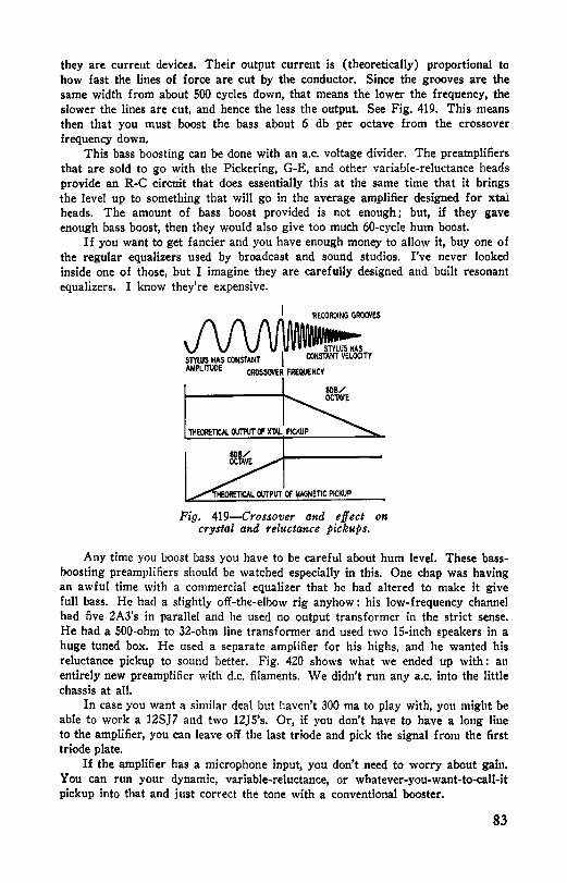
they are current devices. Their output current is (theoretically) proportional to how fast the lines of force are cut by the conductor. Since the grooves are the same width from about 500 cycles down, that means the lower the frequency, the slower the lines are cut, and hence the less the output. See Fig. 419. This means then that you must boost the bass about 6 db per octave from the crossover frequency down,
This bass boosting can be done with an a.c. voltage divider. The preamplifiers that are sold to go with the Pickering, G-E, and other variable-reluctance heads provide an R-C circuit that does essentially this at the same time that it brings the level up to something that will go in the average amplifier designed for xtal heads. The amount of bass boost provided is not enough; but, if they gave enough bass boost, then they would also give too much 60-cycle hum boost.
If you want to get fancier and you have enough money to allow it, buy one of the regular equalizers used by broadcast and sound studios. I've never looked inside one of those, but I imagine they are carefully designed and built resonant equalizers. I know they're expensive.
I RECOROING GROCNES
~ mws HAS CONSTANT I CONSTANT VELOCITY
AMPLITUDE CROSSOVER FREctUENCV
Fig, 419-Crossover and effect on crystal and reluctance pickups.
Any time you boost bass you have to be careful about hum level. These bassboosting preamplifiers should be watched especially in this. One chap was having an awful time with a commercial equalizer that he had altered to make it give full bass. He had a slightly off-the-elbow rig anyhow : his low-frequency channel had five 2A3's in parallel and he used no output transformer in the strict sense. He had a 500-ohm to 32-ohm line transformer and used two 15-inch speakers in a huge tuned box. He used a separate amplifier for his highs, and he wanted his reluctance pickup to sound better. Fig. 420 shows what we ended up with: an entirely new preamplifier with d.c. filaments. We didn't run any a.c. into the little chassis at all.
In case you want a similar deal but haven't 300 ma to play with, you might be able to work a 12SJ7 and two 12JS's. Or, if you don't have to have a long line to the amplifier, you can leave off the last triode and pick the signal from the first triode plate.
If the amplifier has a microphone input, you don't need to worry about gain. You can run your dynamic, variable-reluctance, or whatever-you-wa11t-to-ca1!-it pickup into that and just correct the tone with a conventional booster.
83

If you yearn for a mike and a low-level pickup input, add a tube or build a new amplifier - why not? Of course, you may use an input transformer. Theoretically, that is. The low-level pickups are also low impedance in most cases and stepping them up by a transformer sounds good. The only joker in this is getting a good transformer and then getting enough of that folding stuff to pay for it. They come high and few.
You can cobble up a deal for running low-impedance sources into the amplifier but you take a beating in the matter of voltage any way you look at it. You can couple your source into a cathode instead of a grid and then ground either one that you don't want to play. This sounds easier than it is, because it involves a super-fancy switch on the grid line which will pick up like anything. It also involves weeding the d.c. out of the cathode input somehow or else letting the d.c. flow through the source, which is rarely satisfactory. To isolate with a capacitor you need a big capacitor to get low response into a low-Z input. You may try to beat it with a 600/600 transformer to isolate the source from d.c., but then you've got to use the capacitor anyhow or the 600-ohm secondary winding will short out the bias, and the secondaries of such transformers don't like to have d.c. through them at all. Even when you get the capacitor, you then have to worry about resonances and oscillation.
Oscillation, Hum, etc. Any time there is a lot of gain, you have that worry about oscillation. Coupling
can exist in amazing ways sometimes. Layout is perhaps the most important of all precautions against this as well as against hum. A good layout wires easily, services easily, and keeps in-phase currents away from each other.
One chap, a pretty good man in electronics, had a Ph.D. in physics which impressed me then and he seemed like a sharp lad all around. But the amplifier he built I Was it a stinker! He had a good design. It looked fine on paper and I thought he'd have no trouble at all in building it since he had fooled around with ham work a bit and done radar research during the war. So help us, he had his input running right through the power supply and unshielded. He used metal beam tubes instead of glass. A little open-frame interstage transformer was mounted right next to another open-frame carbon-mike transformer. He had built the whole thing on one of those war-surplus aluminum boxes and it looked nice on the outside; but, when I undid the little clips and lifted the lid, wires bulged out from all over. He hadn't cut them to size at all, just tacked them on hastily and stuffed them in anyhow. The wires were skinned raggedly, and there were cold solder joints all over.
Oddly enough, it played. Heaven knows how it did, but it played. The only trouble was intermittent oscillation that he would stop by banging on the side of the chassis. Finally it reached the point where banging didn't do any good, so he brought it to me to fix up for him. Man, oh man, I had a terrible time tracing out the circuit alone and, when I did, I found three wiring butches. His wife thought him the smartest radioman there was in the world, so I didn't tell on him. I think he told her he wanted to use some of my test gear on it.
I sort of shrugged it off - I wasn't going to rebuild the whole thing for him for love. I told him what to do, and he did it himself at my place in about four or five nights. He finally got it down to where there was just a thin little high singing in it- maybe 10 kc or thereabouts. His speaker didn't put out 10 kc very well, so he took it home as it was.
84

Oscillation is a nasty thing and a lot can be prevented by careful layout and clean wiring. Laying out is simply a matter of keeping input well away from output. I find it easier to make my chassis tong and narrow and run the signal right straight down from one end. The power supply is then at the extreme other end of the chassis and hum control is easy.
Hum is picked up electrostatically most of the time, but coupled fields can induce it too. With very high-gain stuff an occasional shield is necessary; but, if you avoid too much crowding, you can generally get by without it.
If you have to have input transformers and interstage transformers, try to keep them well apart and their cores at 90 degrees to each other. At low levels especially the wiring should be as neat and compact as it can possibly be. Don't place an electrolytic capacitor too close to the rectifier tube and still expect to get good filtering. Those electrolytics are sensitive to heat. The capacitance stays up but the internal resistance goes up, and that makes the filtering value go down.
6SJ7 12SN7 6SJ7 12SN7 (,)---() 270K
+ 'e!e~TT 'lETURN 300MA SUPPLY 5.,_--1-111~
MAGNETIC PICKUP
120K +250-350V
I IVFORIOMVI\ I
680 OUT
15K IOW
Tiq. 420-Equali:·er and amplifier for reluctance pickup. Follow ,manufacturer's advice on shunting the pick,up
with a resistor.
Bathtub capacitors make nice bypasses but allow for mounting them in your layout. Terminal strips and tie points are also nice to have and must be considered.
In short, wire up the whole thing mentally first and then on paper. Erase and try other ways. I like a large sheet of paper with the parts right there and then I sort of play chess with them until I'm satisfied. Then I mark where the holes are to go and use the piece of paper for a template in making the chassis.
Chassis making isn't at all difficult if you have the tools, but it's plenty rough if you haven't. War-surplus aluminum boxes make good chassis. So do ice trays. Also you can buy made-up chassis. For high-gain amplifiers I prefer chassis of either brass or aluminum instead of template (lead-coated sheet iron),
Grouncling is very important. If your chassis is a painted one, scrape off the paint and use a star washer under the parts you mount. If you're tying everything to the chassis at the nearest point, make sure you have good contacts. It is usually possible to get by with that kind of grounding.
Where high-gain, low-level grounds are concerned, I prefer to run a ground bus and tie it to chassis at just one point.
The trouble with grounds is that they aren't grounds. You are really counting on the chassis to carry your currents. It does it, hut, since it has a finite resistance, a signal ground will show a signal from one point on the chassis to another one. This can cause trouble in very high-gain stuff. The simplest way is to use the
85

ground as a shield and not as a conductor also. A shield should ground at only one spot - not both ends. Any time you have
a ground loop you have a potential source of hum and oscillation that in a highgain job can cause plenty of trouble. Tie the tube shields and the wire shields to the chassis at one point only- the closer the better.
The signal ground should be run as a line. Each tube should have its own spot on the bus. Run the bus consecutively from one stage to another. The bus should touch chassis at only one spot.
Just where that spot should be is open to question. One group says at the point of greatest current (such as the output stage), while others say the point of least current. I generally leave until last the business of grounding the bus. Then I listen to the hum level as I ground with a clip lead at this place and that and select the optimum point. I find there is often considerable difference where the ground bus is tied to chassis.
Here's another stunt to rrduce hum: don't use the center tap on the filament transformer. That center tap is often not in the center. Put a 100-ohm potentiometer right across the filament line and tie the center arm to ground. Then adjust the potentiometer for minimum hum. Having been told several times that biasing the filament line several volts up from ground will reduce hum too, I have tried it on four occasions and each time noticed no difference whatever. You may keep it in mind though. It might work for you. I like to shield the filaments of the input tubes.
It's rarely necessary to shield resistors or capacitors, but I've done that too. Simply put large spaghetti over them and then large shielding over that. It's clumsy but effective. For larger capacitors a bouillon-cube can is very handy.
In general, oscillation, hum, and motorboating are all caused by the same sort of fault: insufficient care in layout or poor design.
Fig. 421-A 9mall buff er capacitor killed the hum.
Sometimes hum can be elusive, in which case it might be better to nm, not walk, to the nearest exit. One amplifier I built had only one ambition in life .... to hum. Nothing I could do would stop it. I fooled around the inside of that amplifier with every trick I knew or ever heard of. I hooked in potentiometers to the transformer windings that were supposed to be center-tapped to ground
86

and grounded the pots so I could move my ground from side to side to compensate for any unbalance in the transformers. I raised the level of my filament string from zero to as high as 20 volts. I paralleled all the electrolytics with paper capacitors. I did everything I could think of, humming all the while.
After I had tried all the things I could possibly imagine any reason for, I began doing things without knowing why I was doing them or how they could possibly help. The same idea as beating a tin can to chase the devils away, I guess.
I was fooling around with a small paper capacitor when the hum suddenly stopped. I stopped daydreaming and looked. What I had done was tie this small capacitor from plate to filament of the SY3-GT rectifier of the bias supply. It killed it. No hum. I took it off, and there was hum.
I couldn't figure out just what I was doing and why it should stop hum but I wired the capacitor in. Then it popped itself out-began smoking-so I replaced it with a regular buffer capacitor. Higher voltage. (See Fig. 421.)
12SJ7 SUBSTITUTED FOR 6SJ7
::JI~· / 1., ______ J
B- BROKEN TO INSERT 12V FIL
.,,
Fig. 422-Heating the filament with d.c. eliminated hum.
You see, I still believed in class A 1 then, and I liked the fixed bias so I had a separate bias supply for the 2A3's. Well, not wanting to have that fail and leave B-plus on my plates and so burn up my tubes and output transformer, I had installed a relay. I used the relay coil as a filter choke for the bias supply and had some whacking big capacitors (low-voltage ones) as filters along with it. That must have been the trouble. I had some very funny reactances there, and. it was putting out a peculiar field that would modulate any neighboring r.f. Putting that buffer capacitor across it upset those reactances and resonances and killed the deal.
Since then I have run into the same modulated-hum trouble in other outfits. On three occasions I cured it the same way-right first try out of the box-and the owners thought I was a fine engineer to have diagnosed the trouble so easily. On the other occasion an a.c. line really was causing the hum. We found that out by unscrewing fuses from the household box.
One case I remember was a PA system where the preamplifier tube hummed terribly. The trouble was ground loops. We didn't have time to rewire the whole outfit. It had a 6SJ7 input, and the final was a pair of 6L6's. I pulled out the
87

6SJ7 and substituted a 12SJ7 and then ran a d.c. filament by wiring it in series with the B-minus. The circuit appears in Fig. 422. The total drain was close to 15-0 ma, which just lit the 12SJ7 nicely. The 6L6's didn't seem to miss the lost 12 volts from their plate voilage, and the hum was way, way down. Later the owner rewired the amplifier with more attention to ground loops and cleared up the situation. You could argue that the trouble there was filament induction rather than ground loops, and you might be right. I do know, however, that it was cured by (1) d.c. filaments, (2) rewiring the ground.
One intercom in particular g·ave me a terrific headache. I had made it much too compact for the gaiu, and it oscillated terribly. At first most amplifiers I built oscillated and most oscillators merely amplified. I finally stopped this one by taking out the bakelite frame potentiometer used as gain control and putting in a metal-cased one. The bakelite frame was letting in too much stuff from the nearby output transformer. The metal-cased unit afforded shielding.
Since then I have tried to spread my input and output farther away from each other. It was a good lesson.
I like to avoid electrolytics where possible. Where it's not possible, I like to parallel them with smaller paper units. Several cases of oscillation have been stopped just by shunting a 0.1 paper across a perfectly good 30 mike filter can.
A soldering iron is very important. My preference is for a screwdriver tip with just one side tinned. A temperature regulating stand is nice. A large light bulb in series will also let your iron be hot enough for good joints. More trouble is caused by bad joints than you'd expect possible unless you're a trouble-shooter. Avoid the cheap brands of solder. Eutectic solder is especially good. If it's too expensive, the regular small size rosin-core is good. Use plenty of spaghetti on bare leads of resistors and capacitors - it'll pay off - but avoid the pretty-looking plastic spaghetti. It curls up and dies whenever a soldering iron comes close by. Stranded wire is better than solid - the solid is easier to work, but it has a tendency to break where the insulation has been skinned off. I don't much care for push-back insulation where I live along the seacoast. The stuff seems to soak up salt air and after a short time will arc over to chassis at points. Any time you use tape, use electrical tape. It sticks beautifully and has good dielectrical properties. Don't use transparent tape for insulation. It seems to soak up moisture like a sponge. If you want to lace it up pretty, use a regular waxed linen sail twine, but I'd suggest you neither lace it up nor varnish it until after you've tried it out pretty thoroughly. Anybody can make botches in the wiring, and it's always a nuisance to have to correct them; but when the wiring. is all laced and varnished, it's a lot more than just a nuisance.
88

Chapter 5
Power Supplies
THE matter of power supplills is fundamental in most cases. You know how to hook up a full-wave power supply without any trouble at all. The layout is important there, too, in the matter of providing adequate ventilation.
A glance at a tube manual gives values for minimum impedance for use with certain tubes. A large input filter capacitor is hard on the tube. Also the input capacitor has the toughest time, having the most a.c. applied to it, and is the most likely to break down. For that reason it's a pretty good idea to use a 600-volt paper capacitor there instead of an electrolytic.
A 2-µf bathtub capacitor is good here and mounts nicely. There is a type of paper capadtor in an electrolytic-style round can that is labeled: "Replace• ment for 8-µf capacitor." That is a good one but it isn't anywhere near 8 µf. It runs about 2 µf and makes a nice first filter.
The matter of a bleeder is important because otherwise you may get bitten when you service an outfit. The bleeder doesn't have to be large. It can be almost anything from 10,000 ohms to 1 megohm. The number of seconds it'll take to bleed off the charge from the capacitor is microfarads times megohms plus about 50% more seconds. Nothing tough about this at all.
The filtering is another matter. I prefer the first capacitor to be a paper, the next to be as large as can be had, and the choke also to be plenty large. The current rating should be around 50% greater than you plan on drawing. It's really poor economy to run with no safety factor. If you're building a thousand sets, that's one thing; but if it's just one set, then you can afford to spend a little more on a decent choke that won't run hot. You actually get a break this way in the matter of inductance too. The greater the current the less the inductance, and chokes rarely measure up to what the manufacturers claim anyhow.
Any time you are running enough voltage to have two electrolytics stacked up in series it's good insurance to put resistors across them. The worse of two capacitors will shove the burden of carrying the most voltage across the better capacitor, and the result will be that the good one will pop.
To get bias voltage from the negative lead isn't as popular as it once was, but it's okay if you like back bias. It isn't fixed bias and it isn't self-bias. It's a sort of halfway bias with good features of both. Simply insert a resistor between ground and the center tap of the high-voltage winding. The total current will Row through it, and it's just a matter of I-R drop. The regulation (how close it is to fixed bias) will depend on how much current you are drawing and how
89

constant that current is. If the output tubes are class AB, then it won't be constant; if they are class A, then you don't need any other kind of bias but cathode resistors.
When the transformer has a bit more voltage than is needed, I like to put a power resistor (about 500 ohms or less) between the rectifier filament and the first filter capacitor. It drops the voltage to a usable value and provides a bit more protection for both rectifier and capacitor. See Fig. 501. Its only fault is that it cuts down on the power supply regulation, but that is unimportant in class-A stuff.
B+
Fig 501.-Power supply having adjustable output voltage for class-A amplifier.
The regulation of power supplies becomes important when you are running class AB or class B tubes. Then you need as constant a voltage as it is possible to get. This regulation can be had in any of several ways.
One of the simplest is just to have a great big power supply and bleed off a lot of current constantly. That's what one outfit in Hol!ywood did for a while. They made a pretty fair IO-watt job (they claimed 18 watts undistorted, which was not so) with AB 2A3's in the output. They simply had a 350-ma supply and let about 200 ma run through a bleeder. It's okay but expensive. VR Tubes
Another good way is with VR tubes. These are gas-filled tubes of the neon, argon, or krypton variety and glow prettily in a rig. They will pass up to 40 ma
Al)JUmD FOR MAXIIUM BRLLIMICE OF Vl TU8£S 1N ~ IS LIGIITEST
~1-+-..... : . 003 -
5U4•G a eoov OC3
Fig. 502-Regulated supply using glow tubes in series.
and will light on about 5 or 6, and during that swing of current will maintain a fairly constant 75, 90, 105, or 150 volts across them. Like any neon bulb they aren't perfect, but they aren't bad. Their best range is from 10 to 18 ma and they're about as nice as you could want over that range. They're a little less than that good over the rest of the 6- to 40-ma swing, but they shouldn't vary more than 4 or 5 volts. You can stack VR tubes in series, as shown in Fig. 502, to get a higher value of regulated voltage.
90

There must be a dropping impedance ahead of them - preferably a variable resistor - which you adjust for the most brilliance when the least current is drawn from the supply, Then when the load takes more current the VR's will just take less. To do it fancy, measure the current variation and adjust the resistors so the VR's will be as close to the center of their possible 6 to 40-ma range. Remember they have to stay lit all the time or they aren't regulators.
Certain precautions must be observed with these things. They can oscillate if the proper capacitance is hung across them - regular relaxation oscillator, you see- and it's best not to put a capacitor too near unless it's a fairly small paper. Also they are a bit sensitive to light. They'll have less voltage across them in a bright light than in the <lark. That is a very small matter though.
Electronic Regulation The best regulation (the only good regulation, some say) is obtained by an
electronically regulated supply, This is a very mysterious thing to a good many radiomen and there's no reason why. It is really nothing but an amplifier.
STANDBY SW OFF
ON .,.
-IOH/130MA
IOK/IW - +
REGULATED DC OUTPUT
Fig. 503-Voltage regulated supply 11siiig a 6B4G as the coiitrol tube.
Voltage-regulated power supplies have many applications in radio and electronic fields. Gaseous voltage-regulator tubes such as the OAZ, OB3, and OC3 perform well in circuits in which the load current does not vary over too wide a range, but are not suitable when a variable regulated output is desired.
A circuit of a variable-output regulated supply was presented recently in The C-D Capacitor. This supply, shown in Fig. 503, maintains the output voltage within 1 volt with input voltage or output current variations up to 30%, The output voltage can be set at any desired level between 175 and 300 with a front-panel control. The maximum drain is 60 and 110 ma when the output voltage is 300 and 175, respectively.
In this circuit, the 684G acts as a variable resistor between the filter and the B-plus output terminal. The resistance of this tube is controlled by the bias applied to its grid by the 6SJ7 d.c. amplifier. The tubes are connected so a decrease in output will lower the bias on the 6B4G and decrease its internal resistance to restore the output to its present value. The output voltage is controlled by varying the voltage on the control grid of the d.c. amplifier. This stage is stabilized by passing its cathode current through the 0C3.
91
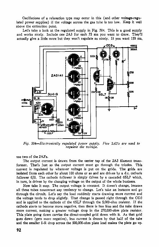
Oscillations of a relaxation type may occur in this (and other voltage-regulated power supplies) if the voltage across the gas tube is too low. Keep it well above the extinction point.
Let's take a look at the regulated supply in Fig. 504. This is a good supply and works nicely. Include one 2A3 for each 75 ma you want to draw. They'll actually give a little more but they won't regulate as nicely. If you want 150 ma,
+300 300114
a-
Fig. 504-Electronically regulated power supply. Pive 2A3's are used to regulate the voltage.
use two of the 2A3's. The output current is drawn from the center tap of the 2A3 filament trans
former. That's just so the output current must go through the triodes. This current is regulated by whatever voltage is put on the grids. The grids are isolated from each other by about 100 ohms or so and are driven by a d.c. cathode follower 6J5. The cathode follower is simply driven by a cascaded 6SL7 which, in turn, is driven by the changing voltage on the output of the whole business.
Now take it easy. The output voltage is constant. It doesn't chana-e, because all these tubes counteract any tendency to change. Let's take an instance and go through the circuit. Let's say the load suddenly starts drawing more current and the voltage tends to drop slightly. That change is passed right through the OD3 and is applied to the cathode of the 6SL7 through the 5,000-ohm resistor. If the cathode starts to become more negative, then there is less bias and the tube draws more current, making a greater voltage drop in the 270,000-ohm plate resistor. This plate going down carries the direct-coupled grid down with it. As that grid goes down (gets more negative), less current is drawn by that half of the tube and the smaller 1-R drop across the S00,000-ohm plate load makes the plate go up.
92

That makes the cathode follower grid go up, and the 6)5 draws more current, making a greater drop in the 75,000-ohm cathode resistance. This makes all the 2A3 grids go up, and the triodes then pass more current (lowering their internal resistance) to bring the output up to where it should be.
6SJ7C2> 6V6·G<2> 003<2>
• ADJUSl' roR 2~V ON 6V6-G Pl.ATES
180
SPKR 100
Fig. SOS-Class-AB beam-power amplifier using an electronically regulated supply.
Now if the line voltage should drop a bit, this regulator will take that lower output voltage and automatically crank it back up to where it belongs. The control on the output merely changes the bias on the 6SL7 grid, and hence the operating point. This means you can select your output votage from about 250 to about 325 and it will stay where you set it.
A good way of evaluating these supplies is by their internal impedance - the lower the better. The internal impedance is nothing but the ratio between the change of voltage to the change of current. This particular supply will show a change of .0375 volt when the current is changed from O to 150 ma. The in-
.0375 ternal impedance is then ---- or 0.25 ohms .
. 150 You aren't limited to 2A3's in your regulated supplies. The 6Y6G in Fig. SOS
is also very nice. Here is a class-AB amplifier with a pair of 6V6G's and a regu-
93

lator using one 6Y6. It works nicely. This is a bit simpler to follow, as less grid swing is required on the 6Y6.
As the signal through the amplifier increases, more current is drawn and the supply voltage tends to drop slightly. That drop is passed to the 6SJ7 grid and the tube draws less current, so its plate goes up. This drags up the grid of the 6J5 cathode follower, and its cathode follows up too. This in turn pushes up the grid of the 6Y6 and it delivers more current until the voltage is once again up to the setting of the control potentiometer. Easy.
30K
IOOY
.._ __ uv TO 2A3 FIL PINS 1-4
Fig. 506-Class-A amplifier having approximately 16 watts output.
This regulation is very necessary in the case of class-AB tubes, as I have mentioned already. I repeat myself. Regulation is necessary with class-AB tubes.
This amplifier isn't bad at all. Those 0D3 tubes in the plate circuit of the output stage are simply to guard against overloading. Pull them out if you like and let it overload on strong signals. It takes a full volt to drive it, so you'll probably want another tube ahead of the input, possibly a tone booster and another tube which would be very nice for phonograph and radio listening.
94

I'd like you to see the diagram (Fig. 506) of an amplifier owned, played, and enjoyed by one radioman. It sounds sweet. The five 2A3's have a 500-ohm coaxial speaker to work into and therefore need no transformer. It really takes a brute of a power supply, as you can see, but my friend promoted the two chokes and the transformer from a chap who became too disheartened to continue with his ham activities. I can recommend this circuit heartily to all those who won't bite their nails over the thought of the electric bill every time they turn it on.
You can vary this amplifier business all over the place. For loads of umph, stack up 6L6G's this same way and throw speaker cones right out of their frames.
., 180K 2W
Fig. 507-Push-pull class-A triode amplifier using 6AS-G's in the output.
If you want to do it cheaper, use the circuit of Fig. SOS and put in 6L6's in AB2 which, with such nice regulation, will give up to about SO watts. Don't forget that you'll need more current, and so you should add at least one more 6Y6G to the regulator as well as increase the size of transformer and choke. You can put the other 6Y6 in parallel if you observe the good-practice rule of inserting a SO-ohm resistor in each parallel plate and ISO-ohm in each parallel grid.
One man has a pair of class-A 6L6's (Fig. 305) operating into a cheap 10,000-ohm output transformer to feed his woofer, and a single 2A3 (Fig. 411) amplifier feeding a cheap 1,800-ohm transformer going to a high-frequency horn cluster. On the low amplifier he has plenty of capacitance from signal to ground so as not to Jet any high notes through. On the high amplifier he has small coupling capacitors to keep the bass notes out. His deal sounds fine, too.
95

On my outfit I use a pair of 6AS's in class A, feeding a sort of station-house boom-box and horn-cluster system. In another room I have a single 6V6G (Fig. 402) feeding a pair of small accordion-edge speakers. The larger outfit sounds better, but not much. The complete circuit of the larger amplifier is shown in Fig. 506.
You can do pretty much as you like, combining a little of this and a little of that. The important thing is to have an outfit whose sound you like. They're your ears!
96

Chapter 6
Phonographs
J F by now you have a nice amplifier and speaker, what are you going to feed into it? Radio is lovely - except for the commercials and political speeches and such, Everybody has a radio. There are many times more radios than bathtubs in the country. Hitch in your radio; it will sound wonderful.
Then there is phonograph music. Great technical skill and true artistry go into many discs to provide you with your own request programs any time you want them. Whether your taste is for Spike Jones or the New York Philharmonic, every town has shops where you can get records you will enjoy.
Some record faults have already been mentioned. There are probably less eccentric holes and groove imperfections in the vinylite (L. P. and regular) discs than the shellacs but these faults still occur and should be guarded against.
The business of making a record is a highly specialized one and involves great care in plating large masters and making matrices and stampers and such. Any trouble anywhere along the production line makes for a poor record. The stampers are a critical link in the chain and there are a lot of stampers made from each master. Pressings are made from the stampers-one after the otherregular mass production stuff. Naturally these stampers don't last indefinitely and so periodically a stamper is discarded and a new one hauled out. Some companies use a stamper up to 1000 times, others perhaps less.
Now this obviously results in a production run from a stamper and the quality on this run steadily goes down until it's so bad they throw out the stamper. Pressing # 1 is pretty sure to be a good one while #999 is bound to be pretty poor. If there's any way of telling whether the record you buy is #1 or #999 I don't know what it is. I have bought some that must have been early pressings from a stamper and a few that were most likely stamped just before they threw the dang thing away.
So far as I can find out, this applies to all records-not just the shellacs. It's quite possible that the L. P.'s have a production run that is shorter. I'd be surprised, however, if it were a bit shorter than absolutely necessary. The recording companies are out to cut corners wherever they can and stampers cost money.
The burden of all this adds up to the simple fact that, whether it's shellac or vinylite, 78, 33 1/3 or 45 rpm, you can get a stinker. I've heard lots of shellac records outplay vinylite. Just because it's an L. P. doesn't mean it has to be good.
97

Of course, vinylite is a nicer surface than shellac. Pressing for pressing, you'll enjoy vinyl!te more than shellac if high fidelity means anything at all to you. The quieter surface allows higher notes to be recorded and heard so distortion must be lower. The early pressings on vinylite used the same stampers in many cases and the records showed some distortion and general fuzziness in the highs on the vinylites-these highs couldn't even be heard from shellac discs, so a lot of chaps formed a poor idea of the vinylites.
While it's true that a good many of the vinylite re-pressings are slightly on the crummy side, they can still be played and enjoyed by simply limiting your highs, and your surface noise will be away down from the shellac. The newer recordings are excellent (when you have an early pressing) as there is nothing to limit the recording engineers. The early masters didn't have to be so clean because the state of the art hadn't gone beyond a certain limit.
Examine the vinylite records carefully before you pay for them unless you deal with just one shop as I do. Once in a while the disc will slip out of the envelope and the grooves will be dusty and unplayable. I even saw one that was as slick as grease ... there wasn't a sign of a groove on it. It was a freak, of course, but it pays to examine with care.
The 78 rpm vinylite are mighty nice and seem to resist needle wear much longer than the shellac-which is what you'd expect from a more homogenous surface. The 33 1/3 rpm L. P. discs can be sweet but they can also be sour in just a few times at bat. They're highly damageable by hands, poorly ground or worn styli, an unbalanced tone-arm, and a number of other things. Some chaps claim that even looking at them hard will knock down the highs.
These longer-playing records get that way by squeezing their grooves close together and also making the grooves narrower. This means a narrower needle. The recommended radius of the tip is 0.001 inch rather than 0.003 or 0.0035 inch and the pressure shouldn't be over 0.3 ounce. This generally means a new pickup.
These L. P. records are nice if you like the longer selections. Having some 20 minutes of music to a side is positive luxury compared to the 78 rpm discs. Musically, that is. In regards to the technical end-well, up to now I have yet to hear an L. P. that can compare favorably to a clean ffrr recording. Almost but not quite. The slower groove speed makes for certain limitations and the narrower grooves make for more. I have heard echoes from one groove to another, rumble to the point where it is a nuisance (evidently recorded into the disc too) a severe loss of highs in just a few playings in some discs. In short, the recordings are not perfect. They probably can and will be much better eventually.
Don't get me wrong. I'm not saying they're terrible. Just that they aren't always as nice as I expected them to be. I think the engineers tend to try to get too high a level on them whim they boost the highs as the grooves approach the center, I think they can be improved to where they are every bit as nice as the 78 rpm vinylite discs.
My own preference is for 16-inch 33 1/3-rpm transcriptions which have for some time been of an homogeneous material so that the surface is low. If I could afford it I would have the N. B. C. Thesaurus service.
RCA went at the problem a slightly different way. They analyzed the situation to arrive at their 45 rpm discs. (I am sure they didn't just subtract 33 from 78.) They employed top-flight mathematicians to get the most enjoy•
98
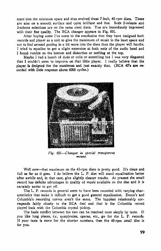
ment into the minimum space and thus evolved these 7-inch, 45-rpm discs. These are also on a smooth surface and quite brilliant and fine. Both 5-minute and 3-minute selections are on the same sized discs. You are immediately impressed with their fine quality. The RCA changer appears in Fig. 601.
After buying some I've come to the conclusion that they have designed both records and player as a unit to give the maximum of music in the least space and not to fool around putting in a bit more into the discs than the player will handle. I tried to equalize to get a slight extension at both ends of the audio band and I found rumble on the bottom and distortion or nothing at the top.
Maybe I had a bunch of duds or culls or something but I was very disgusted that I couldn't seem to improve 011 that little player. I really believe that the player is designed for the maximum and just exactly that. (RCA 45's are recorded with little response above 6000 cycles.)
Fig. 601-Changer in special transparent mount.
Well now-that maximum on the 45-rpm discs is pretty good. It's clean and full as far as it goes. I do believe the L. P. disc will stand equalization better after awhile and, in that case, give slightly cleaner results. At present the small record has definite advantages in quality of music available on the disc and it is certainly easier to get oft'.
The L. P. records in general seem to have been recorded with varying char• acteristics that make it difficult to get a good general equalization. Decca's and Columbia's recording curves aren't the same. The happiest relationship corresponds fairly closely to the RCA deal and that is the Columbia record played back with the Columbia crystal pickup.
The basic conflict between the two can be resolved most simply by taste. If you like long pieces, i.e., symphonies, operas, etc., go for the L. P. records. If your taste is more for the shorter numbers, then the 45-rpm small disc is for you.
99

For the slow records you need as smooth and heavy a turntable as you can get. Also a very rigid motor-board prevents the pickup vibrating from both needle and base.
Pickups The pickup itself is quite a problem. Depending on your taste and pocket,
you can spend anywhere from $4 to $250 and possibly more. I'd rather listen to a carefully equalized cheap one than to an expensive one that has not been properly equalized.
Just now there seems to be a sort of fad for the variable reluctance pickups and a popular theory I have run into suggests that no equalization is needed with them. Phooey. Double phooey. No pickup has yet been made that didn't require equalizing. These VR cartridges are no better in this respect than a crystal.
A crystal pickup is a lot better than some give it credit for. There's a fairly wide tolerance in their manufacture and you can get a honey or a lemon. One of my favorite pickups of all time has been an old prewar RCA Cobra-head with new dampers and a whale of an Alnico magnet (I have taken milliwatts from it-not just microwatts).
The cleanest crystal pickup I ever heard approached this closely in cleanliness. This was a terrible-looking affair. It consisted of an old (but selected) B-2 Astatic cartridge (the Bakelite-encased type) which was fastened with adhesive tape to an old piece of yardstick and mounted on a couple of hinges that provided swivel action in two dimensions. That pickup sounded wonderful. I taped the head on at an angle to minimize tracking error and used shadowgraphed steel needles; it did just beautifully. The curve just happened to fall right for the amplifier I used at that time.
Due to urging from the XYL, I made a better looking pickup arm for it out of walnut, but the tone wasn't nearly as good, and we went back to the yardstick arm. In fact, we used that pickup arm up until I got a Brush PL-50.
At the radio station our main pickups were old RCA magnetic heads put on long arms. They were reworked slightly but were almost the same as when RCA put them out. Those old pickups, when equalized, sounded good, and, until I began using that taped-on crystal cartridge, I used a similar old RCA Cobrahead magnetic. It gouged the records a bit but it sounded better than anything else. As far as quality went, it was better than any crystal except my adhesivetape model and the Brush PL-50.
The Brush PL--50 is an expensive model (no longer available, they tell me) and gouges records only slightly. They avoid excess gouging by having good compliance. The stylus is fastened to the crystal by a thin wire that is flexible enough so that the crystal itself doesn't have to bend very far. This, of course, makes for less output, but it's worth the sacrifice. The cheaper model PL-20 has the same sort of rigging, but the wire is stiffer and the output is greater. Also it isn't as clean. During the war they made just one cartridge to replace either kind, and I suppose the replacement model was somewhere between the two insofar as quality of output and record wear went.
Astatic and other companies have also come out with lightweight arms with permanent styli, and some of them aren't bad at all. Manufacturing tolerance has a wide spread here, and you might get an excellent one or you might get a
100

stinker. Any crystal device has a resonance somewhere and, on most of them, the resonant frequency is close to 12 kc. This means, of course, that the output will rise at that frequency and the slope can be observed down around 6 and 7 kc. This favors harmonics a bit and the output is not as clean as from a head which isn't resonant anywhere close to the audio band.
For this reason a lot of people prefer the variable-reluctance head which, I maintain, is just an old-fashioned magnetic head brought up to date a bit. Those old magnetics are still nice if you put fresh dampers in them. If you .vant to get fancy and put in a he-man magnet of Alnico ( or something similar), you can get a very large output voltage from them. Of course, the bass end must be boosted in any magnetic device.
Fig. 602-The author keeps adding parts . .. and still it doesn't work!
Some pickups have a built-in resonant affair that boosts their bass output, but it still isn't the answer. They don't boost it far enough because they can't do it that way without running into other and greater troubles.
Other companies try to use arm resonance to build up their weak points, but it's a poor deal. Just like using resonant filters inside the amplifier, they tend to sing (or growl) at their own frequency when something jolts them. If enough
101

damping is used to prevent this singing or growling, then you're about back where you started from. Any tone correction can be done with R-C circuits and done better by the home listener.
Probably the item that made my old adhesive-tape pickup sound so much better than commercial arms using the same head was simply the low Q of the soft yardstick and the adhesive tape. I like a nonresonant arm and a nonresonant head.
These newer magnetics have a good deal to commend them. Their response curve isn't too good, but they are cleaner if used with a good arm. As for other considerations, the crystal is a lot easier to use with a set and the magnetic is a little sturdie1·. The crystal will vary a bit with temperature and humidity, and the magnetic won't. The crystal is also easier to equalize. As a guess backed by some experience with both, I'd say they both gouge records the same.
The arms themselves are important also. Of course, there is the matter of arm resonance. Any arm has it somewhere, and it's desirable to have it damped way down and have it out of the audio band. Most of the commercial arms (in the medium- and low-price field) are too short and too lightly damped (their Q is too high). Most radio stations use fairly heavy arms and long ones too. Tangent heads are nicer than straight ones. The stations I have worked for used mostly long straight arms with magnetics (old RCA cobra heads, slightly reworked or else the Western Electric 9-A).
You can bend up a lightweight dural arm without much trouble but it will likely be lacking in bass response as well as resonate unpleasantly. Look at it this way: The needle is going back and forth and, if the arm is compliant enough to go back and forth with it, you get less twist and the output will be very low.
The Brush arms have little lead weights at the crystal end to add mass, and the bass is obviously down a bit when these are removed. I played around with an Astatic HP arm for awhile and found a resonance around 150 cycles that I didn't like. I melted an old tallow candle into the underside of the arm and then added more lead to the back end and played around with it that way. By the time I had worked that resonance down the scale to where it didn't bother me any longer, I had added a whacking amount of mass; and I then had too much bass, so I had to fadoodle around with the equalizing network again. Incidentally, that long narrow (16-inch style) Astatic arm w·orks beautifully with a G-E head if you melt about 3¼ inches of candle into the underside and then counterbalance to about ¼ ounce at the needle.
When I speak of heavy arms, I mean massive. A free swivel at the back end is very desirable for easy tracking-takes less weight to push the stylus down to the bottom of the grooves, and hence less wear on the records.
The only thing wrang with a massive pickup arm is that it will not play as well a record with an eccentric hole. To me that's not a fault because I hate those records anyhow. I consider it inexcusable for the recording companies to punch their holes off center, but they often do.
The stylus is important in tone considerations as well as in the matter of record gouging. Permanent styli are nice in a lot of ways, but it means either changing the whole head or going to a certain amount of fuss in cementing on a new point. Of course you can cement on a small-radius paint for L. P. discs as easily aR a standard one. Use a point radius of .001 inch for the L. P. records.
Watch your stylus. Get a magnifier and look at it every once in a while.
102

If your glass is good and your light likewise, you'll be able to see the wear on it. Don't use on your good records a stylus having shoulders. If you wait until the grooves change color as the stylus passes, then you've waited too long.
I have heard some very nasty distortion that disappeared when the stylus was changed, but don't rely on that. Check the shape of the point with a jeweler's loupe or equivalent magnifier.
As to the replaceable needles-well, right away you're swinging more mass back and forth in the record grooves when you have a needle chuck. That may or may not be all right. Some folks swear by-cactus needles because (it is said) the material is softer than the record and therefore can't possibly harm the records. Maybe that's right and maybe it isn't. After all, case-hardened steel can be sawed by soft copper that has diamond chips imbedded in its edge. The soft cactus can pick up a crumb of dust or other material and do just as much damage. I don't use cactus needles because I like to hear high notes.
Furthermore, I don't believe in babying records quite that much. Everybody has to draw a line, and my line is at cactus needles. If it's going to· wear out my records to play them with a well-ground jewel point (and I don't think it does any more than playing them with cactus), then let them wear out. Having bought the records to play them, I don't intend to listen to half of the notes just so they won't wear out. I daresay my recording of "Eine Kleine N achtmusik" has been played between 150 and 200 times and it still sparkles. I've always used a good sapphire on it. It's a good clean pressing (maybe a low number from the stamper), and it has always sparkled. Probably the highs are down a littleit would be surprising if they weren't-but it sounds good to me and the scratch level isn't high at all.
The wear on records is more a matter of moving mass than anything, I believe. The lighter the armature the better. A short arm can give considerable twist to the needle between grooves at the edge and grooves at the center, and for that reason I use a longish arm. A tangental head mounting is nice, too, as tracking error can be critical.
The vertical angle is very important, I think, and that's one of the reasons records wear out faster on a record changer. Mount your pickup arm carefully according to the directions from the manufacturer. Mount your homemade arm so that the head itself is parallel with the turntable.
Of course the turntable should be level. Also the pickup arm should be counterbalanced. Have the swivel loose enough to track easily. No point in groove-skipping. The rule of thumb I've followed along this line is simple. Just connterhalance till it will barely track and then take off weights until the pressure at the needle is twice the amount necessary for tracking. With my present arm this figures out about 0.3 ounce.
Some people don't like to shut down lids over their turntables. That's okay as far as it goes if you keep the dust off. Dust is an enemy of high notes. Another item here is the acoustic output of your head. If you like your music from the speaker at a low level and have no lid, then you may be annoyed by the acoustic sound from the pickup head itself. Among crystals, the only one I know of that has a really low acoustic output is the RCA crystal.
I recommend a lid over the box. If the pickup still annoys you with its acoustic output, you can pad it. Felt is nice for this, but you can also use burlap or old sweaters and turkish toweling and other fabrics. Green felt pasted on the
103

inside of the lid doesn't look bad and it completely absorbs the acoustic output from the pickup.
If you use a record changer for all your music, then you want a lid. Record changers are nice for the lazy man, hut they seem to collect even more dust than a straight turntable unit. I can't think why this is so, but it seems to be true. Also a changer has all sorts of clicks and buzzes and what-not that most folks would rather not hear.
Without any lid on the changer, the dust will work down into the motor, making cleaning and overhauling necessary a bit sooner. That is something that is necessary with any kind of motor.
Motors
Most of the motors sold today are little rim-drive affairs, squirrel-cage motors or something similar. The rim drive is effected by a rubber puck wheel. This will last a long time but will run better if given a little service once in a while. Wash and powder the rubber drive and clean the dust out of the motor and bearings. A little sewing-machine oil is better than a lot of Three-in-One.
Next step up would be motors of the Green Flyer type. We used two at one radio station for close to 14 houra a day and serviced them once a month. When they were three years old, they showed no great wear.
Among the heavy-duty, 2-speed, 50-60-cycle motors there is an important thing to remember. The little felt pad that acts as a brake in the governor must be washed in carbon tetrachloride or benzine every so often and relubricated. If the motor is a Garrard or Benson, lubricate it with vaseline lightly. If it's a General Industries or a Loring, use only neatsfoot oil on it. If you can't find a name plate on the motor and you aren't sure, sniff at the pad and see what it had on it before. Neatsfoot oil has a distinctive smell and vaseline hasn't. Put the wrong lubricant on this pad and you'll have trouble with wows.
Next up on the list are the heavy machined tables driven by a large, wellcased motor. The drive can be by a dental belt or direct shaft or rubber tire. Of the three the rubber-tire drive is the noisiest. The direct-drive table is very quiet acoustically but puts out a noticeable field, so shield extra carefully. The dental-belt drive (or tape drive) is nearly foolproof and very flexible. Motors are generally a Bodine or equivalent and the tables are very smooth and nice, but they cost a lot.
Flocked surfaces are very popular, but I prefer a piece of smooth sheet rubber. Felt is good but must be brushed often. The flocked surface will hold a lot of dust before it damages the record, but it generates static electricity on the disc and you'll have to wipe it off the disc carefully. Record brushes of plush are cheap.
Record Changers
Record changers, on the other hand, deserve all the curses there are so far as I'm concerned. They belong in the same malevolent class of all automatic gadgets-automatic toasters, automatic chokes, automatic waffle irons, etc. Such devices are inspired by fiends and conceived in infamy by the ungodly. Amen!
With rare exceptions, record changers do not provide high fidelity. Some have knife blades that go in between discs-except when you try to use a thicker-
104

than usual Columbia record on them and then they go between one disc. You can sweep the chips out every week.
Other models enlarge the center hole until you get wows. Most of them pile one disc on another and, on loud passages, make for a certain slip that certainly doesn't do the lands a bit of good, and in addition lets the top record slow down until the music level drops again.
The angle of attack of the stylus varies as the records pile up on the turntable, which doesn't do any good. Also the tripping mechanism makes for more wear on one side of the stylus and grooves from about halfway in.
All in all a record changer is just a lazy man's device even when it is working properly. A lazy man who likes his fidelity high will generally mount a straight turntable and pickup unit right alongside his easy chair so he can change the records without getting up.
Pressure was Lrought to bear on me to get a record changer, for the play room downstairs. I finally succumbed and went downtown to look them over. I watched them play and grudgingly conceded that wear on the center hole seemed preferable to slicing the thick discs down to the same size as the thin ones, so I eliminated all but the center-post changers.
I hesitated between two for awhile but finally decided on one because it looked as though it had less pot metal underneath and I also thought replacement parts would be simpler to get. So I did buy one. Mostly for dance music a11d Harry Horlick and the stuff they call program bulk.
Fig. 603-N ow the te11sio11s ca1i be controlled.
After I built the box and put it in, I called the XYL and piled on a bunch of Strauss waltzes. I pushed the button. It just walked right through that stack of records. Changed them all in jig time and played nary a note.
"Well," commented the XYL. "That was a short symphony, wasn't it? I guess I wasn't listening carefully enough-who was the composer?"
I muttered in my beard and tried again with the same results. Then I tore into the thing.
An hour and a half later I called her again. I was sweaty and exasperated, but this time it played the records. But now it wouldn't change them. I had to push the button each time. She laughed a silvery little ripple and wondered where we could find a radio serviceman.
We needn't go into all the details but suffice it to say my soul was considerauly lacerated and my pride well tromped b.y the time I got that thing to behave.
Adjusting record changers isn't hard once you get onto it. I'm an expert now. You stand the thing on three beer bottles and look up from underneath
105
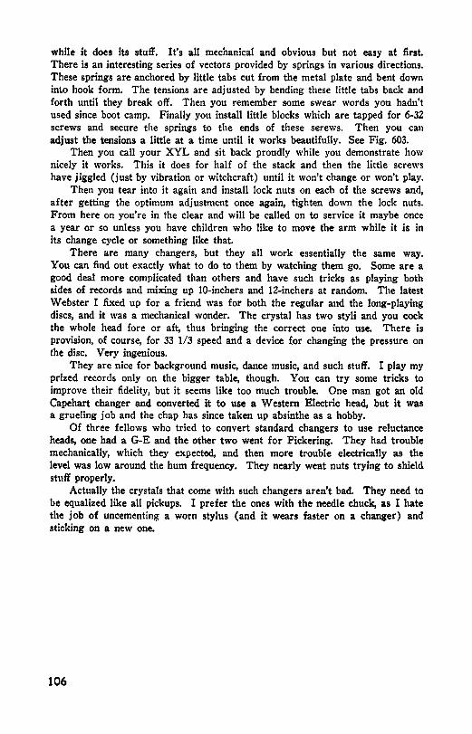
while it does its stuff. It's all mechanical and obvious but not easy at first. There is an interesting series of vectors provided by springs in various directions. These springs are anchored by little tabs cut from the metal plate and bent down into hook form. The tensions are adjusted by bending these little tabs back and forth until they break off. Then you remember some swear words you hadn't used since boot camp. Finally you install little blocks which are tapped for 6-32 screws and secure the springs to the ends of these s£rews. Then you can adjust the tensions a little at a time until it works beautifully. See Fig. 603.
Then you call your XYL and sit back proudly while you demonstrate how nicely it works. This it does for half of the stack and then the little screws have jiggled (just by vibration or witchcraft) until it won't change or won't play.
Then you tear into it again and install lock nuts on each of the screws and, after getting the optimum adjustment once again, tighten down the lock nuts. From here on you're in the clear and will be called on to service it maybe once a year or so unless you have children who like to move the arm while it is in its change cycle or something like that.
There are many changers, but they all work essentially the same way. You can find out exactly what to do to them by watching them go. Some are a good deal more complicated than others and have such tricks as playing both sides of records and mixing up 10-inchers and 12-inchers at random. The latest Webster I fixed up for a friend was for both the regular and the long-playing discs, and it was a mechanical wonder. The crystal has two styli and you cock the whole head fore or aft, thus bringing the correct one into use. There is provision, of course, for 33 1/3 speed and a device for changing the pressure on the disc. Very ingenious.
They are nice for background music, dance music, and such stuff. I play my prized records only on the bigger table, though. You can try some tricks to improve their fidelity, but it seems like too much trouble. One man got an old Capehart changer and converted it to use a Western Electric head, but it was a grueling job and the chap has since taken up absinthe as a hobby.
Of three fellows who tried to convert standard changers to use reluctance heads, one had a G-E and the other two went for Pickering. They had trouble mechanically, which they expected, and then more trouble electricatly as the level was low around the hum frequency. They nearly weat nuts trying to shield stuff properly.
Actually the crystals that come with such changers aren't bad. They need to be equalized like all pickups. I prefer the ones with the needle chuck, as I hate the job of uncementing a worn stylus (and it wears faster on a changer) and sticking on a new one.
106

Chapter 7
Some Last Words About High Fidelity
I HOPE I have mentioned some items in the building of high-fidelity systems that you didn't know before. If so, you probably figure you got your money's worth. There are, however, just a few more items not to be overlooked.
One is frequency range. Don't be misled by the unscrupulous blandishments of the radio salesmen. They talk blithely and glibly about a range of 20 cycles to 20,000 cycles.
The lowest note available on a butl-fiddle is 40 cycles-a full octave above that low limit- and the highest key on a piano is about 4,600 cycles. I've worked with music a bit-I used to earn my living as a musician long ago-and I honestly don't think a piece of piano music exists which calls for either the highest or lowest keys. I never was a bull-fiddler, but I am sure the dog-box slappers don't often go for the bottom string wide open. Rarely is there any music as low as 40 cycles. That's terribly low.
Even 60 cycles is amazingly low. Hitch a speaker to the light line (through a transformer) and listen. Well, that one you're hearing is 120 cycles because the level is too high and the speaker is distorting by 80 or 90%. Crank the level way down and get your ear up in there. Now. Hear that real low tone? That's 60 cycles.
Even if yoi1 manage to get an amplifier and speaker system that would go down to 20 cycles (or even 40), you wouldn't find much down there to listen to. You'd pay through the nose for those bottom notes and then you'd never hear them because music isn't written that low.
How about the high end? A piccolo is about the highest, and its top tone is around 7 kc. How often is that played? Very rarely. A triangle? Cymbals? Tambourine? Sure, they go up but only to around 8 kc at the very top. Key jingling is high, too, but how many orche!tral scores have parts for a ring of keys?
I'm not preaching low fidelity now. I'm just trying to counteract all you may have absorbed from listening to salesmen or reading ads. Twenty cycles to 20 kc indeed I Now that you have some knowledge about high fidelity-think about it before you plunk down that folding stuff for those extra notes.
Your neighborhood movie house has a range of SO cycles to 8 kc, and that's plenty good. They haven't scratch to deal with, but they do have flutter and other noises that amount to nearly the same thing.
Tone balance is very important. Have your high and low cutoffs so that their product is 400,000. Trial and error shows clearly that 100 to 4 kc or 50
107
to 8 kc or 25 to 16 kc all sound good. If you extend your highs, you should also extend your bass end farther or the tone balance will be awry.
The telephone has a range of approximately 200 to 2,000 cycles and voices sound normal over it-even a bass voice which extends down to around 80 cycles. Now the reason for this is very interesting.
Our ears are use-d to hearing certain fundamentals always accompanied with certain harmonics. We recognize a person's voice by the harmonic structure rather than by the fundamental. When a bass voice comes over a telephone wire, only the harmonics are transmitted but the ear on the other end reinserts the fundamental so that we think we hear it.
This is very important. If you don't have bass response below 100 cycles, you can still hear a ~ousa.phone, because the ear, hearing the sousaphone harmonics, automatically supplies the missing fundamental.
This can be shown very easily. Do you remember that Ray McKinley number that was so popular back before the war-"Celery Stalks at Midnight?" It is still being played from time to time. It has some low trombone notes, solo, with the others tacit, at several places toward the end of the piece. Those notes are somewhere around 70 cycles and, like all instrumental tones, rich in harmonics.
You can play that record on a cheap little a.c.-d.c. player with a 117L7 and a 3-inch speaker. The tube probably doesn't amplify 70 cycles and the transformer certainly doesn't pass it to the speaker. If it did, the speaker wouldn't put it out. But you can play that record on that cheap little squeak box and hear those low trombone tones. Again a matter of the ear supplying the missing fundamental.
So don't let yourselves be led astray by people who are trying to get you to buy some particular item. They'll tell you you must have flat response from 20 cycles to 20 kc, and they'll try to kid you into believing you'll get it if you buy their products.
Advertisers and salesmen study hard to be able to make other people think they need something they don't. Just don't let them push you around.
You have the interest and the ability to make yourself a system that will satisfy you completely, and it should satisfy your ears and not the ideas of some set manufacturer's engineers, salesmen, and copy writers.
If you need more knowledge, that can be had. If you need more ability, that can be acquired. None of this is hard. Go to it. It's a lot of fun.
Decibels vs. Voltage and Power
The decibel chart on page 109 indicates decibels (db) for any ratio of voltage or power up to 100 decibels. For values over 100 db, or for more exact values between 20 and 100 db, a modest amount of arithmetic is necessary. Here are some typical examples :
1) Find the db corresponding to a voltage ratio of 104. Subtract 100 from 104. This leaves us with two numbers-100 and 4. The db corresponding to a ratio of 100 is 40 db. Now we must multiply 100 by a number such that the result is 104. Multiplying 100 by 1.04 will give tt~ 104. Now look up 1.04 in the voltage ratio column. This corresponds to approximately .3 db. Our answer is 40 db plus .3 db or 40.3 db for a voltage ratio of 104.
108
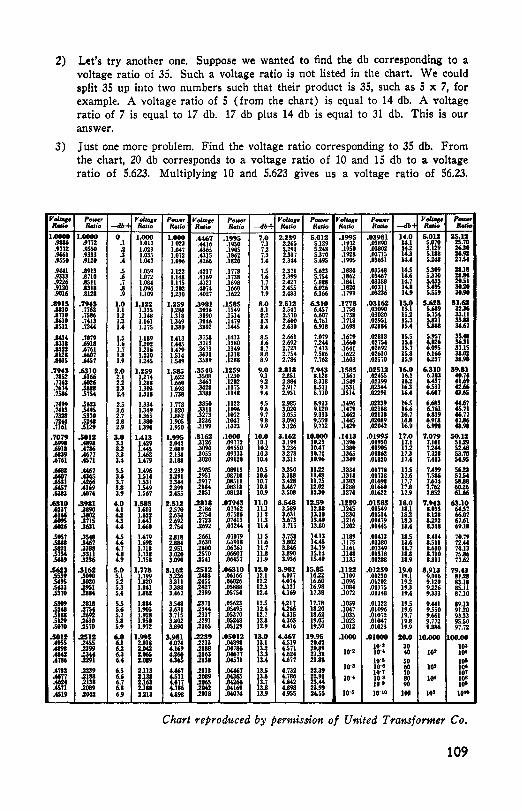
2) Let's try another one. Suppose we wanted to find the db corresponding to a voltage ratio of 35. Such a voltage ratio is not listed in the chart. We could split 35 up into two numbers such that their product is 35, such as 5 x 7, for example. A voltage ratio of 5 (from the chart) is equal to 14 db. A voltage ratio of 7 is equal to 17 db. 17 db plus 14 db is equal to 31 db. This is our answer.
3) Just one more problem. Find the voltage ratio corresponding to 35 db. From the chart, 20 db corresponds to a voltage ratio of 10 and 15 db to a voltage ratio of 5.623. Multiplying 10 and 5.623 gives us a voltage ratio of 56.23.
Yol,qe PotHr Yol101e Powe, Yolu,1e Power J'olta1e p..,,., Voll.1e p..,,., Yol,,,1e ,._ - Ratio -db-+ Ra1io Ratio Ratio Ra,io -db+ Ratio Rati.o Rado ftfllio -db• Rfllio -1.0000 1,0000 0 1.000 1.000 .4467 ,1995 7.0 2.239 5.012 .1995 ,03981 14,0 S.012 25.11 .9916 .9772 .I 1.012 1.023 .4416 .19SO 7.1 2.265 5.129 .1972 .03890 14.1 S.070 25.70 .9772 .9550 .2 1.023 1.0.7 .4365, .190S 7.2 2.291 5.248 .1950 .03802 14.2 5.129 26.30 .9661 .9333 .3 1.035 1.072 .431S .1862 7.3 2.317 S.370 .1928 .03il5 IU 5.188 26.92 .95SO .9120 .4 1.M7 1.096 .'266 .1820 7.4 2.3ft 5.495 .1905 .03631 IU 5.248 27.54
.!MU .1913 .s 1.059 1.122 .'217 .17i8 7.5 2.371 5.623 .1884 .035'8 JU S.309 28JI
.9333 .1710 1 1.072 1.1'8 .4169 ,li38 7.6 2.399 S.754 ,1862 .03467 14.6 5.370 21M
.9226 .ISII :. 1.084 1.175 .4121 .1698 7.7 2.'27 S.888 .1841 .03388 1'-7 SA33 29.51
.9120 .1318 1.096 1.202 .40i4 .1660 7.ll 2.4S5 6.026 .1820 .03311 IU SA95 38.20
.9016 .ll128 .9 1.109 1.230 .t027 .1622 7.9 2.483 6.166 .1799 .03236 IU 5.559 38.90
.191S ,7943 1.0 1,122 1.259 .3981 .1585 8.0 2.512 6.310 .1778 .03162 1S.O 5,623 31.61 .1110 .7762 I.I 1.135 1.288 .3936 .1549 8.1 2.541 UST .ma .03090 IS.I 5.689 32.36 .1710 .7S86 1.2 1.148 1.318 .3890 .1514 8.2 2.Si0 6.607 .1738 .03020 15.2 S.75' 33.11 .1610 ,7413 1.3 1.161 1.349 .38'16 .1479 8.3 2.600 6.761 .1718 .02951 15.3 5.ll21 33.lll .am ,72" u 1.175 1.380 .3802 .1445 8.4 2.630 6.918 .1698 .0288t 15.4 s:asa 34.67
.1414 ,7079 1.5 1.189 1.413 .3758 .1413 8.5 2.661 7.019 .1679 .02818 15.S 5.957 3SA8
.1311 .6911 1.6 1.202 1.445 .3715 .1380 8.6 2.692 7.2ft .1660 .0215' 15.6 6.026 36.31
.1222 .6761 1.7 1.216 1.479 .36i3 .1349 8.7 2.723 7.413 .1641 ,02692 15.7 6.095 37.15
.1121 .6607 1.8 1.230 1.514 .3631 .1318 8.ll 2.15, 7.586 .1622 .02630 15.ll 6.166 38.02
.1035 .6457 1.9 1.245 1.549 .3589 .1288 8.9 2.786 7.762 .1603 .02570 15.9 6.237 31.90
,794S .6310 2.0 1.259 1.585 ,3548 .1259 9.0 2.818 7,943 ,1585 ,02512 )6.0 6.310 39,11 .7852 .6166 2.1 1.274 1.622 .3508 .1230 9.1 2.851 8.128 ,1167 .02455 16.1 6.383 40.74 .7762 .6026 2.2 1.288 1.660 .3467 .1202 9.2 2.88' 8.318 .1549 .02399 16.2 6.457 41.69 .7674 .5888 2.S 1.303 1.698 .3428 ,1175 9.3 2.917 8.511 .1531 :~ffl 16.3 6.531 42.66 .7586 .575' 2.4 1.318 1,738 .3388 .1148 9.4 2.951 8.710 .1514 IU 6.607 43.65
,7'99 .5623 2.5 1.334 J.7i8 .3350 .1122 9.5 2.985 8.913 ,1496 .02239 16.S 6.683 44.67 ,7413 .5495 2.6 1.349 1.820 .3311 .1096 9.6 3.020 9.120 .1479 .G2188 16,6 6.761 45.71 .m1 .5370 2.7 1.365 1.862 .3273 .1072 9.7 3.055 9.333 .1462 .G2138 16.7 6.839 46.77 .7244 .5248 2.ll 1.380 1.905 .3236 .IM7 9.8 3.090 9.550 .1445 .G2089 16.1 6.918 47.16 .7161 .5129 2.9 1.396 1.950 .3199 .1023 9.9 3.126 9.772 .1'29 .02042 16.9 6.998 48.98
,7079 .5012 3,0 l.413 1.995 .3162 .1000 10,0 3.162 10.000 .1413 .01995 11.0 7,079 so.12 .6998 A898 3.1 1.'29 2.042 .3126 .09772 10.1 3.199 10.23 .1396 .01950 17.1 7.161 51.29 .6911 .6786 3.2 1.445 2.089 .3090 .09550 10.2 3.236 10.47 .USO .01905 17.2 7.2ft sua .6839 .6677 3.3 1.462 2.138 .3055 .09333 10.3 3.273 10.72 ,1365 .01862 17.3 7.328 53.70 .6761 .6571 3.4 1.479 2.188 .3020 .09120 IG.4 3.311 10.96 .1349 .01820 17.4 7.413 54.95
.668! M67 3.5 1.496 2.239 .2985 .08913 10.S 3.350 11.22 .1334 .01778 17.S 7.499 56.!3
.6607 .4365 3.6 1.514 2.291 .2951 .08710 10.6 3.388 11.68 .1318 .01738 17.6 7.586 57.54
.6531 .4266 3.7 1.531 2.344 .2917 .08511 10.7 3.428 11.75 .1303 ,01698 17.7 7.674 SUI
.6457 .4169 3.8 1.549 2.399 .288t ,08318 10.ll 3.467 12.02 .1288 ,01660 17.8 7,162 60.26
.6383 .4074 3.9 1.567 2.455 .2851 .08128 10,9 3.508 12.30 .1274 .01622 17,9 7.ll52 61.66
,6310 .S981 4.0 1,585 2,512 .2818 .07943 u.o 3.548 12,S9 ,1ZS9 .01585 18.0 7.943 63.10 .62S7 .3890 u 1.603 2.570 .2i86 .07i62 II.I 3.589 12.ll8 .1245 .015'9 II.I 8.035 64.ST .6166 .3802 4.2 1.622 2.630 .2754 .07586 11.2 3.631 13.18 .1230 ,01514 18.2 1.128 66.07 AG9S .3715 u 1.641 2.692 .2723 ,074.U 11.3 3.673 IU9 .1216 .01'79 18.3 8.222 67.61 .6026 .3631 u 1.660 2.75' .2692 .07244 JU 3.715 13.llO .1202 ,Oltt5 18.4 8.318 69.18
.5957 .35'8 u 1.679 2.818 .2661 .07079 11.S 3.758 14.13 .1189 .01413 18.S 1.41' 70.79
.5111 .3467 4.6 1.698 2.114 .2630 .t.1918 11.6 3.802 14.45 .1175 .01380 18.6 8.511 72.44
.5121 .3388 4.7 1.718 2.951 .2600 .06761 11.7 3.ll46 14.79 .1161 .01349 18.7 8.610 74.13
.575' .ml u 1.738 3.020 .2570 .06607 11.8 3.ll90 15.14 .1148 .01318 18.ll a.no 75.ll6
.5689 .3236 4.9 1.758 3.090 .25'1 .G6457 11.9 3.936 15.49 .1135 .01288 18.9 8.llll 77.62 ,5611 .Sl62 s.o 1,778 S.162 .2S12 ,06310 lZ.O 3,981 15,85 ,1122 .01259 19.0 8.913 79.43 .5559 .3090 5.1 1.799 3.236 .2483 .G6166 12.1 4,027 16.22 .1109 .01230 19.1 9.016 81.28 .5495 .3020 5.2 1.820 3.311 .2455 .06026 12.2 4.074 16.60 .1096 .01202 19.2 9.120 83.18 .5433 .2951 5.3 IMI 3.388 .2'27 .05888 12.3 UZI 16.98 .1084 .01175 19.3 9.226 85.11 .5370 .2884 5.4 1.862 3.467 .2399 .05754 12.4 4.169 17.38 ,1072 .01148 19.4 9.333 87.10 .5309 .2811 5.5 1.884 3.548 .2371 .05623 12.S 4.217 17.78 .1059 .01122 19.5 9.441 89.13 .5248 .275' 5.6 1.905 3.631 .2344 .05'95 12.6 4.266 18.20 .1047 .01096 19.6 9.SSO 91.20 .5188 .2692 5.7 1.928 3.715 .2317 .05370 12.7 UIS 18.62 .1035 .01072 19.7 9.661 93.33 .5129 .2630 5.8 1.950 3.802 .. 1291 .05248 12.8 4.365 19.05 .1023 .OIM7 19.8 9.772 95.50 .5070 .2S70 5.9 1.972 3.890 .2265 .05129 12.9 U16 19.50 .1012 .01023 19.9 9.886 91.72
.5012 .2SIZ 6.0 1.99S 3,981 .2239 ,OSOlZ 13.0 4,467 19.95 ,1000 .01000 20.0 10.000 100.00 .4955 .2455 6.l 2.018 4.074 .2213 .04898 13.1 4.519 20.42 10·• 30 103 A898 .2399 6.2 2.842 4.169 .2188 .oti86 13.2 4.571 20.ll9 .6142 .:m 6.3 2.065 4.266 .2163 ,M677 13.3 4.624 21.38 10·• 10·• 40 10' 10' .4786 .2291 6.4 Z.089 '-365 .2138 .MS71 13.4 4.677 21.ll8 10·• 50 10' .4732 .2239 6.5 2.113 U67 .2113 -04467 13.S 4.732 22.39 10·• 1o·e 60 103 IOI
]O·T 70 IOT .6677 .2188 6.6 %.138 t.571 .2089 .M365 13.6 4.786 22.91 10·• )0·8 80 10' IOI .4624 .2131 6.7 2l63 4.677 .2065 .04266 13.7 U42 23.« 10·• 90 100 .6571 .2089 6.8 2.188 4.786 .2042 -04169 13.ll U98 23.99 .4519 .2042 6.9 2.213 U98 .2018 -04074 13.9 4.955 24.55 10·• ]0·10 100 10' 10••
Chart reproditced by permission of United Transformer Co.
109

Index .
AB-Triode Amplifier • . . . . . . . . . . . . . . . . 66 Accidental Resonance . . . . . . . . . . . . . . . . L 2 Acoustic Impedance . . . . . • . . . . . . . . . . • 16 Air Mass . • • . . . . . . . . . . . . . . . . . . . . . . . 22 Amplification ~•actor . . . . . . . . . . . . . . . . . 61 Amplifier Distortion . . . . . . . . . . . . . . . . • 8 Amplifiers:
AB-Triode Amplifier . . . . . . . . . . . . . 66 Balanced Output . . . . . . . . . . . . . . . . 60 Bass Response . . .. .. . . . . . . . . . . . . 12 Bias ...... , .. , ........ , ........ 89 Class A ..... , .................. 48 Class AB ...................... 44 Decoupling Filter ................ 74 Design ............... 02, 63, 64, 65 Direct Coupled . . . . . . . . . . . . . . . • . • 51 Distortion . . . . . . . . . . . . . . . . . . . . . . 8 Intermodulation . . . . . . . . • . . . . . . . . 13 Intermodulation Distortion • • • . . • • • 14 Loftin-White ••••••....••.•.....• 52 Miller Effect . • . • • • . . . • . . . . . . . • . • 72 Oscillation • . . . • • . . . . . . . . . . . . . • 12 Output Transformers . . . . . . . . . . . . . . 86 Phase Distortion . . . . . . . . . . . . . I 4, 78 Power Amplifiers .. , . . . . . . . . . . . . . 35 Power Output . , , . . . . . . . . . . . . . . . . 35 Push-Push . . . . . . . . . . . . . . . . . . . . . . 44 Testing with Square Waves ...... , 12 'l'ransients . . . • . • . . . . . . . . . . . . . 7, 11 Treble Resronse . . . . . . . . . . . . . . . . • 12 Voltage Amplifiers ..............• 53 Volume Expansion ..............• 66
Bullie Anti-resonance ................ 24 Bass Booster .................... , , 76 Bass Cutoff . . . . . . . . . . . . . . . . . . . . . . . . 71 Bass Horns ........................ 82 Bass Loss •...•................•..•. 82 Bass Response ..•..... , . . . . . . 12, 87, 70 Beam Power Tubes • . . . . . . . . . . . . • 38, 40 Bias .••••••••••••••••••......•..• , 89 Biasing Power Amplifiers • . . . . . 49, 50, 51 Bleeders • • • • . • • • • • • • . . • . . . . . • • • . • • 89 Box: Resonance • . • • . • . . . . . . . . . . . . . . . 18 Cactus Needle ...••••............... 108 Capacitors, Electrolytic • . . . . . . . . . . . . . 89 Capacitors, Paper • • • • • • . . . . . . . . . . . . 89 Cathode-Coupled Inverter ............ 47 Cathode-Follower Inverter . . . . . . . . . . . 4~ Cathode Loading • . • . . . . . . . . . . . . . . . . 41 Class A • • . • . • . . . . . . . . . . . . . . . . . . . . . 4B Class AB •.................. , . . . . . . 44 Constant-Impedance Net work . . . . . . . . . 28 Contact Bias ............... , ....... 68 Crossover Networks:
Constant-Impedance .............. 28 m-Derived •• , . . . . . . . . . . . . . . . . . . . 28
Crystal Correction . • . . . . . . . . . . . . . . . . 81 Crystal Pickup ...................•. 100 Crystal Pickup Output . . . . . . . . . . . . . • • 83 Crystal Resonance .................• 100 Current Feedback .• (see Inverse Feedback) D.C. Filaments ••••..........•...... 87 Decibel Chart ••.................... 109 Decoupling Filters . . . . . . . . . . . . . . . . . . 7 4 Degenerative Feedback
(see Inverse Feedback) Direct-Coupled Amplifiers . • . . . . . . . . . . 51
110
Distortion . . . . . . . . . . . . . . . . . . . . . . • . • 7 Dual Systems . . . . . . . . . . . . . . . . . . . . . . 25 Electrolytic Capacitors . . . . . . . . . . . . . . . 88 Electronic-Regulated Power Supply ... , 91 Electronic Regulation ............. , , 91 l!Jqualization • , •••.................. 80 Ex:pollential Horn •................ , 25 Feedback Bass Boost . . . • . . . . . . . . . . . . 59 Feedback Calculations ..••.....•... , , 64 ~•eedback Loop ... , . . . . . . . . . . . . . . . . . 57 Feedback 'l'reble Boost . . . . . . . . . . . . . . . 59 Filtering . . . . . . . . . . . . . . . . . . . . . . . . . . 89 Fixed Bias ................ , . . . . . . . 51 Flat Baffle •................... , 17, 22 Flat-Topping .•..................... 10 Floating Inverter • . . . . . . . . . . . . . . . . • . 45 Frequency Limits • . . . . . . . . . . . . . . . . . . 69 Frequency of Sound . . . . . . . . . . . . . . . . 23 Frequency Records . . . . . . . . . . . . . . . . . 18 Fuses ............................. 50 Gm ••••.........•.............•..• 61 Gas Voltage Regulator Tubes ......... 90 Grounds •. , . . . . . . . . . . . . • . . . . . . • . . . . 85 Harmonics . . . . . . . . . . . . . . . . . . . . . . . . . 9 Helmholtz Resonator . . . . . . . . . . 17, 21, 22 High Fidelity ...................... 107 High-Fidelity Transformers ........... 37 High-Frequency Oscillation . . . . . . . . . . 12 High-Low Booster . • . . . . . . . . . . . . . . . . 77 Horn and Box: ...................... a4 Horn Cluster . • . . . . . . . . . . . . . . . . . . . . al Horn Design . . . . . . . . . . . . . . . . . . . . . . . 2'6 Horns , , ........................... 25 Hum:
D. C. Filaments . • . . . . . . . . . . . . . . . 87 Decoupling Filters . • . . . . • . . . • . . . . 7 4 Grounds • • • . • • . • • . . . . . . . . . . . . . . 85 Hum Level . . . . • • . . . . . . . . . . . . • . . 83 Layout . . • • • . . . . . . . . . . . . . . . . . . . • 84 Signal Ground . . . . . . . . . . . . . . 115, 86
Hum Level . . . . . . . . . . . . . . . . . . . . . . . . 83 Infinite Baffle . • . . . . . . . . . . l 7, 21, 22, 31 Intermodulation . . . . . . . . . . . . . . . . . . . . 13 Intermodulation Distortion . . . . . . . . . . . . 14 Internal Impedance of Tubes . . . . • . . • . . 71 Inverse Feedback ...••.••• 53, 54, 55, 58 Inverse Feedback Tone Control ....... 75 Labyrinth . . . . . . . . . . . . . . . . . . . . . . . . . 20 Layout • . • . . . . . . . . . . . . . . . . . . . . . . . . . 84 Leakage Reactance . . . . . . . . . . . . . . . . . . 88 Load Line , . . . . . . . . . . . . . . . . . . . . . . . . 63 Loftin-White Amplifier ............... 52 Loudspeakers:
Acoustic Impedance . . . . . . . . . . . . . . 16 Baffle Anti-resonance . . . . . . . . . . . . . 24 Basa Horns •.•••................ 82 Box Dimensions .•............... 19 Box Resonance . . . . . . . . . . . . . . . . . . 18 Damping • • . . . . . . . . . . . . . . . . . . . . . 39 Distortion • . . . . . . . . . . . . . . . . . . . . . 7 Dual Systems . • . . . . . . . . . . . . . . . . . 25 J~xponential Horn . . . . . . . . . . . . . . . • 25 Flat Baffle ..•................ 17, 22 Helmholtz Resonator . . . . . . . L 7, 21, 22 Horn and Box . • • . . . . . . . . . . . . . • • 34 Horn Cluster • , . . . . . . . . . . . . . . . . . . Bl

Horn Desirn .... , , •........•• , . 26 Horns •....... , .... , ............ 25 lmped11nee .................. 1~, 41 Infinite Baffle .......... 17, 21, 22, 31 Labyrinth .................••. , • 20 Multispeaker Installations .....••• , 24 Padding .. , .. , ................. 17 Phasi111r ...................•• 31, 33 Q •.•••..................•••••• 20 Resonnnc·e . . . . . . . . . . . . . . . . . . . 23, 39 Slot .......................... , 18 Slot Size . . . . . . . . . . . . . . . . . . . . . . . 20 Small .......................... 38 'l'uned Box . . . . . . . . . . . . . . . . . . . . • 17 Tuned Box Q .....•..........••• 20 Woofer•'l'weeter .................. 33
Low-Cut Control . . . . . . . . . . . . . . . . . . . 75 Low Fidelity . , ................ , ...• 107 Low-Ii'requency 'l'ransmission . . . . . . . . . 69 Low-Level Pickup , . , ••.......... , , , 84 Low-mu Triodes ................. , . . 88 L. P. Discs .••.•.••..•...•.....• , , , 98 Magnetic Pickup Output . . . . . . . . . . . . . 88 Maximum Power Transfer ........• , , , 88 m-.Derived Network ................. 28 Microphones ................. , . , , , , , 69 Miller Effect ................... , 71, 72 Motorboati ng ...•............. , , , , , , 78 Motors .........................•.. 104 Mu ••.•..••••..••..•....••••.••••• 61 Multispeaker Installatio11s . . . . . • • • • • • . 24 Negative Feedback ••••••.....• 54, 55, 58 Oscillation • • . . • . . . . . . • . . . . . • • • • 12, 84 Output Transformer Efficiency .•• , , • • • 86 Output 'i'ransformers •••••........ , • , 36 Output Tubes .............. , ..... , , 88 Overloaded Sine Wave . . . . . . . . . . . . . . 10 Overloading •••••.............. , , • , , 10 Phase Distortion ............. , . . 14, 78 Phase Inversion , . . . . . . . . • 44, 45, 46, 47 Phase Inverters:
Cathode-Courled ...........•• , • • • 47 Oathode·Follower ............... , 48 Floating .•• , , , , , ........... , .. , . 45 Split Load .•..•.... ; ........... , 46 Standard Inverter ..•.......... , , 45
Phase Shift ...... , • . . . . . . . . . . . . . . . . 57 Phasing ........................... 31 Phonographs ...........•..•.•.••. , • 97 Pick-ups: ·
Arm . . • . . . . . . • . . . . . . . . . • • 100, 102 Arm Resonance ••..•..•.•.•• , , ••• 102 Bass Loss • .. . .. . .. .. .. .. . .. • • • • 82 Cactus Needle ...............•..• 108 Crystal . . . . . . . . . . . . . . . . . . . . . 88, 100 Crystal Correction ............• , • • 81 Crystal Output ...... , ...... , , , .• 88 Crystal Resonance ................ 100 Distortion ......... , . . . . . . . . • • • • 8 Equalization ......... , . . . . . . . . . • 80 Low Level . . . . . . . . . . . . . . . . . . . . . • 84 Magnetic ...•........ , , , , , . . . • • • 83 Push-Pull , , , ...•...... , , . , . . . . • • 49 Stylus ..• , , , ........... , , , ...... 102 Variable Reluctance ...... , , ..... , 101
Plate Load ... , , , ........... , ... , .. 68 Plate Resistance , , ...............•• , 61 Power Amplifier .................•• , 35 Power Output ................... , • • 35 Power Supplies:
Bleeders . .. .. .. .. .. .. . .. .. .. • .. • 89 Capacitors, Electrolytic • • . . • • . • . • • • 89 Capacitors, Paper .• , • . . . . . . . . . • • • 89 Decoupling Filters ••.....•... , • , 74 Electronic Regulation • • . . . . . • . • • • 91 Filtering , ..•••••.. , . . . . . . . • . • • • 89 Gas Regulator Tubes , , . . . . . . . . • • • 90 Regulation •••••.•.... , . . . . . . • . • • 90 Voltaire Regulator Tubes (See VR Tubes)
VR Tubes •. , . , .....•.. , .•.••• , • 90 Power Tube Ionization .........•...• 49 Pre-amplifiers . , . . . . . . . . . . . . . . . . . . . . 83 Push-Pull Pickup . . . . . . . . . . . . • . • • • . • 49 Push-Push Amplifiel's . . . . . . . . . . . . . • . . 44 Up •••••.••.•.............•.••.•. 61 Record Changers:
AdjustmenlR .................••• 105 Motors ....................•.•.• 104
Records: Distortion ........ , . . . . . . . . . . • • • 8 Frequency .......•.....• , • , • , , • • 18 L. P ............... , ....... , •.. 98 Scratch ........•. , , •..•..• , •••• 80 Scratch Filters . . . . . • . . . . . • . • • • . • 79 Shellac •.•..••...........•.••..• 97 Stampers .... , . . . . . . . . . . . . . . . . . . 97 Vlnylite ......... , ..... , . . . . . . . • 97
Regenerative Feedback : . . . . . . . . . . . . . 54 Regulation .. , , , , . . . . . . . . . . . . . . • . . . . 90 Resonance in Speakers . . . . . . . . . . . . . . 2 8 Scratch l!'ilters , , , , •.............•. , 79 Second Harmonic Distortion . . . . . . . . • • 9 Self-bias .•••• , ••• , . . . • . . . . . • . . . . • • 49 Shellac RecordR . . . . . . . . . . . . . • • • . . . . 97 Signal Ground . . . . . . . . . . . . . . . . . . 85, 86 Slot Size .. , . . . . . . . . . . . . . . • . . . . . . . . 20 Small Speakers . . . . . . . . . . . . . . . • . • . . 33 Solder ............................ 88 Soldering Irons . . . . . . . . . . . . . . • . • . • • 88 Sound Frequencies . . . . . . . . . . . • • . . • • • 23 Sound Impedance ............•.•••. , 39 Sound Wavelength •.........••. , ••. , 2a Breakers ( See Loudspeakers) Split-load Inve1·ter ••••••.•.......•• , 46 Square Wave Generator ...........••• ll Square Wave Testing ..........••.• , • 12 Stampers , , , , , , .••............... , , 97 Standard Phase Inve1·tel' ......... , , , 45 Stylus .... , ..••................. , 102 Stylus Distortion .................• , 8 Third Harmonic Distortion ........• , , 10 Time Constants ••..•.•............ , • 70 Tone Balance ......•............ , , , 107 Tone OontrolB:
Bass Booste1· . . . . . . . . . . . . . . • • . • • • 76 Bass Cutoff ...............•.. , • • 71 High-Low Booster ...•........•• , 77 Inve~se Feedback .......•....•••• 75 Low-Cut •..•................•• , 75 Toned Circuit . . . . . . . . . . . . . . . • • • • 75
Transconductance • . . . . . . • . . • • • • . • • • • 61 Transformers:
Bass Response . . . . . . . . . . • . . . . . • • U 7 High Fidelity .................. , 37 Inductance . . . . . . . . . . . . . . . . . . . . • • U 8 Leakage Reactance ............• , • 38 Primary Impedance . . . . . . . . . . . . . • 41 Primary Inductance ..........•.. 88 Testing .. , . , , .................. 87
'franslent Distortion .............. , • 7 Transients • • • • • • . . . . . . . . . . . . . . . . • . . 11 Treble Resronse • . . . . . . . . . . ....•• , , • 1 ll Tube Capacitance ....•........... , . , 71 Tube Characteristic Curve ....••.•••. , 68 Tubes:
Amplifi.cation Factor . . . . . . . . . . • • . • 61 Beam Power • , .......•....•• 88, 40 Capacitance •....•....••....••• , • 71 Characteristics • . . . . . . . . . . . . . . . • • • 68 Excitation .••..•.............• , , 60 Fixed Bias •....•........... , • • • 51 Gas ••.•.•••......•........•• , •• 90 Gm •.••••••.•••...•........•••• 61 Internal Impedance .........•.•• , 71 Ionization , , , , ••••••........• , • • 49 Load Line • , , , ..•........ , . . • • • 68
111

Low-mu Triodes .............. , , , 88 Miller Effect , . . . . . . . . . . . . . . . . . . . 71 Mu , , , , , , , , .................... 61 Outrut Tubes . . . . . . . . . . . . . . . . . . . 8 8 Plate Load . . . . . . . . . . . . . . . . . . . . . . 68 Plate Resistance ................. 61 Transconductance . . . . . . . . . . . . . . . . 61 VariR ble Bias . . . . . . . . . . . . . . . . . . . 60 VR Tubes • . . . . . . . . . . . . . . . . . . . . . 90
Tuned Box Q .. .. .. .. .. . . .. .. • .. • .. 20 Tuned Boxes .. .. . .. .. . . . . . . .. . .. .. 17 Tuned-Circuit Tone Control . . . . . . . . . . 75 Unbypassed Cathode . . . . . . . . . . . . . . . . 58 Undistorted Power Output . . . . . . . . . . . 38 Variable Bias ................... , . . 60
112
Variable Blas and Drive ...... , . , , . , , 60 Variable Drive .......... , , . , . . . . . . . 60 Variable Reluctance Pickup , . , , . , . , , , 101 Vinyllte Records .......... , , , , , .. , , 97 Voltare Amplifier Design ... 62, 68, 64, 65 Voltage Amrlifiers ........... , , ... , , 58 Voltage Feedback ( See In verse Feedback) Voltage Regulated Power
Supplies ••..........•• , 91, 92, 93, 94 Voltage Regulator Tubes (See VR Tubes) Volume Expansion .................. 66 VR Tubes , ••...................... 90 Wavelength of Sound ................ 23 Woofer-Tweeter .................... 33