high capacity feed rates up to 10,000ppd (200kg/hr) capacity feed rates up to 10,000ppd (200kg/hr)...
TRANSCRIPT

CHLORINATORS.COM | 772-461-0666
Series CL-40/60/80/100 Gas ChlorinatorHigh Capacity Feed Rates Up To 10,000ppd (200kg/hr)
The SUPERIOR™ Series CL-40/60/80/100 Gas Chlorinator is a
state-of-the-art, vacuum-operated, solu! on feed type, for very high
chlorine gas feed rates up to 10,000 pounds per 24 hours (200 kg/
hr). The vacuum regulator is mounted onto a special wall moun! ng
adaptor, using a very heavy-duty, posi! ve yoke clamp connec! on
that allows for ease of maintenance. A chlorine gas fl ow meter
panel indicates the amount of chlorine being fed and may be located
wherever it is most convenient and safest. Chlorine fl ow rate is
manually adjusted and this equipment’s design permits easy addi! on
of a number of automa! c fl ow rate control devices. A high effi ciency,
water operated ejector produces the vacuum necessary to operate
the system. A back-fl ow check valve system prevents pressurized
water from entering the chlorinator. A spring-opposed diaphragm
vacuum regulator controls the chlorine gas fl ow rate and also acts as
the safety shut-off valve.
DESCRIPTION
WHAT MAKES THE SUPERIOR™ DESIGN BETTER?
Even though lower capacity gas chlorinators have evolved
signifi cantly since the introduc� on of the all-vacuum direct cylinder
mounted design in 1960, the higher feed rates, from 4,000 to 10,000
PPD (80 to 200 KG/HR) have suff ered from stagna� on in design and
materials of construc� on. While the “Sonic” fl ow regula� ng principle
was adopted to virtually every brand of low and medium capacity gas
chlorinator, the higher capaci� es were treated as some kind of design
museum from the 1960’s. Huge vacuum regulators and complicated
diff eren� al regulators, with large numbers of parts made of materials
such as PVC were used by every manufacturer. The design innovators
of the 1960’s and 1970’s just seemed to stop at that higher level of
chlorine gas feed. SUPERIOR engineers had a long history of using
newer, more chlorine resistant, stronger materials as well as striving
for simpler, more compact, and easier to maintain equipment.
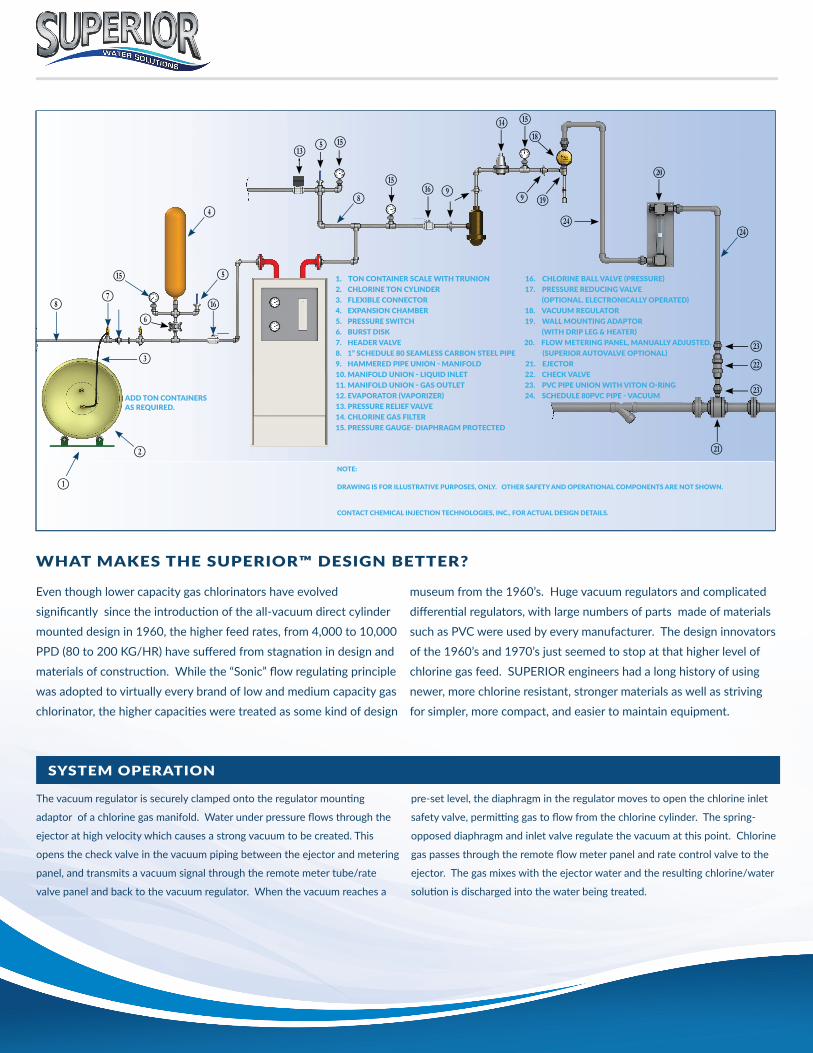
The vacuum regulator is securely clamped onto the regulator moun� ng
adaptor of a chlorine gas manifold. Water under pressure fl ows through the
ejector at high velocity which causes a strong vacuum to be created. This
opens the check valve in the vacuum piping between the ejector and metering
panel, and transmits a vacuum signal through the remote meter tube/rate
valve panel and back to the vacuum regulator. When the vacuum reaches a
pre-set level, the diaphragm in the regulator moves to open the chlorine inlet
safety valve, permi� ng gas to fl ow from the chlorine cylinder. The spring-
opposed diaphragm and inlet valve regulate the vacuum at this point. Chlorine
gas passes through the remote fl ow meter panel and rate control valve to the
ejector. The gas mixes with the ejector water and the resul� ng chlorine/water
solu� on is discharged into the water being treated.
SYSTEM OPERATION
NOTE:
DRAWING IS FOR ILLUSTRATIVE PURPOSES, ONLY. OTHER SAFETY AND OPERATIONAL COMPONENTS ARE NOT SHOWN.
CONTACT CHEMICAL INJECTION TECHNOLOGIES, INC., FOR ACTUAL DESIGN DETAILS.
1. TON CONTAINER SCALE WITH TRUNION 16. CHLORINE BALL VALVE !PRESSURE"
2. CHLORINE TON CYLINDER 17. PRESSURE REDUCING VALVE
3. FLEXIBLE CONNECTOR !OPTIONAL. ELECTRONICALLY OPERATED"
4. EXPANSION CHAMBER 18. VACUUM REGULATOR
5. PRESSURE SWITCH 19. WALL MOUNTING ADAPTOR
6. BURST DISK !WITH DRIP LEG & HEATER"
7. HEADER VALVE 20. FLOW METERING PANEL, MANUALLY ADJUSTED.
8. 1” SCHEDULE 80 SEAMLESS CARBON STEEL PIPE !SUPERIOR AUTOVALVE OPTIONAL"
9. HAMMERED PIPE UNION # MANIFOLD 21. EJECTOR
10. MANIFOLD UNION # LIQUID INLET 22. CHECK VALVE
11. MANIFOLD UNION # GAS OUTLET 23. PVC PIPE UNION WITH VITON O#RING
12. EVAPORATOR !VAPORIZER" 24. SCHEDULE 80PVC PIPE # VACUUM
13. PRESSURE RELIEF VALVE
14. CHLORINE GAS FILTER
15. PRESSURE GAUGE# DIAPHRAGM PROTECTED
ADD TON CONTAINERS
AS REQUIRED.
B
C
H
D
P
E
F
NF P
I
P
I Q
Q J
O P
S
J T
G
Y
U
Y
X
W
X
V

Series CL-40/60/80/100 Gas Chlorinator
FLOW METER CAPABILITIES
SUPERIOR™’s modular design concept allows
the chlorine gas indica� ng meter and fl ow rate
control valve to be located wherever it is most
convenient for the operator, and also in the
safest loca� on. A dual English/Metric scale
variable area fl ow metering tube is provided
with a maximum capacity of 4000 PPD - 80
Kg/hr (MODEL CL-40), 6000 ppd - 120 Kg/hr
(Model CL-60), 8000 PPD - 160 Kg/hr (Model
CL-80), 10,000 ppd - 200 Kg/hr (Model CL-100)
. All metering tubes are interchangeable and
may be changed in the fi eld without special
tools.
MODULAR DESIGN
SUPERIOR™ High Capacity Gas Chlorinators
have been designed to give the maximum
fl exibility in system installa� on. Each
component of the chlorinator, vacuum regulator,
metering tube panel, check valve, and ejector
can be placed wherever it is safest and most
convenient for opera� ng personnel. The
regulator may be mounted on the chlorine gas
manifold in a safe storage area while the remote
meter tube panel is placed in an easily accessible
place since it operates completely under
vacuum. The ejector can be located wherever
plumbing and/or hydraulic condi� ons make it
most desirable. Modular design also makes it
easy and inexpensive to expand or upgrade the
system.
MATERIALS OF CONSTRUCTION
One of SUPERIOR’S™ major compe� � ve
advantages is the use of the fi nest, strongest
and most durable materials available. Extensive
use of Fluoroplas� cs and fi berglass reinforced
thermoplas� cs allow SUPERIOR™ Gas
Chlorinators to withstand a! ack by chlorine in
any form and to give the longest opera� onal life.
Many parts are guaranteed for the life of the
equipment against chlorine damage.
FEATURES
The SUPERIOR™
“Super” High Capacity
series is very unique,
using a proven “Sonic” gas
fl ow regula� ng system that
replaces outdated diff eren� al
pressure regulators,
reducing the number of
parts and signifi cantly
increasing reliability.
1
All vacuum fi # ng holes
are heavily reinforced
to prevent the
possibility of cracking from
over-� ghtening fi #ngs.
5
The en� re inlet valve
assembly is easily
removed as a complete
“capsule” without the need to
diasassmble the en� re vacuum
regulator. When cleaning or
maintenance is required, this
makes the job so much easier
and requires almost no parts
replacement other than a few
o-rings when necessary.
3
Extensive use of
Flouroplas� c materials
throughout the system
ensures against dry, wet, or
liquid chlorine a! ack, and
greatly increases reliabilty
and equipment life.
7
All vacuum regulator
parts are made of
ABS, PVDF, HALAR,
Tantalum or Tefl on materials
to eliminate poten� al damage
by liquid chlorine. No PVC is
used in this vital component.
PVC will be severely damaged
by liquid chlorine.
2
A “Diaphragmless”check
valve design off ers very
low cracking pressure
and fric� on loss. Check
valves are complete modules
and can be close-coupled
to the ejector or located
anywhere in the vacuum
piping system for maximum
fl exibility.
6
All external bolts and
nuts are Titanium for
complete corrosion
resistance..a SUPERIOR™
exclusive. There are no
stainless steel or monel nuts
and bolts to corrode and
freeze up in the presence of
moist chlorine gas. There are
also no plas� c threads used.
4
All-vacuum opera� on,
combined with modular
design of the major
opera� ng components, allows
pressurized chlorine gas to be
isolated from the opera� ng
areas for greater safety.
8

835 EDWARDS RD., FORT PIERCE, FL 34982 | T. 772!461!0666 | F. 772!460!1847
SUPERIOR"CHLORINATORS.COM | CHLORINATORS.COM
Series CL-40/60/80/100 Gas Chlorinator
STANDARD ACCESSORIES (Included with Chlorinator)
1 - Remote Vacuum Regulator 1 - Adaptor Manifold
1 - Remote Metering Panel 10 - Lead Adaptor Gaskets
1 - Remote Ejector Assembly 1 - Vent Insect Screen
1 - Check Valve Assembly 25’ - 3/8” Vent Tubing
OPTIONAL ACCESSORIES AVAILABLE
Inlet Water Assembly Gas Masks
Wall Manifold Kits Gas Detectors
Booster Pumps Scales
Automa# c Flow Propor# oning Residual Analyzers
Automa# c Residual Control Others Available
Ton Container Adaptors
SPECIFICATIONS
The chlorinator shall be SUPERIOR™ MODEL CL-40/60/80/100
manufactured by Chemical Injec! on Technologies, Inc., Ft. Pierce, Florida,
and shall have a maximum capacity of _______ pounds per day (Kg/hr)of
chlorine feed and shall be equipped with a chlorine fl ow meter of _______
pounds per day (Kg/hr).
The chlorinator shall be of modular design consis! ng of a vacuum
regulator, fl ow meter/rate valve panel, check valve and ejector. Each of
these assemblies shall be capable of being individually located wherever
safety and/or operator convenience dictates.
The vacuum regulator shall mount directly on the regulator moun! ng
adaptor of a chlorine gas wall manifold by means of a posi! ve yoke type
clamp. The chlorine valve/chlorinator inlet adaptor shall be constructed of
corrosion-proof fl uoroplas! c material which shall be inert to the eff ects of
wet, dry or liquid chlorine. No PVC materials shall be used in the vacuum
regulator design to avoid damage by liquid chlorine. A pressure relief valve
shall be incorporated into the vacuum regulator to prevent pressure from
building up in the system. All external screws and nuts shall be made of
Titanium to prevent corrosion.
The fl ow meter/rate control valve panel shall be separate from the
vacuum regulator and ejector assemblies and shall be capable of
moun! ng wherever it is safest and most convenient for opera! ng
personnel. “Sonic” Chlorine gas fl ow regula! on design shall be used,
without need of diff eren! al pressure regulator(s).
Vacuum shall be created by a fi xed-throat venturi/ejector system. A
spring loaded “diaphragmless” type check valve system shall prevent water
from entering the gas system. The ejector assembly shall be capable of
withstanding water pressure up to 150 PSIG (10.2 Bars).