high capacity bag magazine volume i - university …€¦ · · 2013-05-08high capacity bag...
TRANSCRIPT

HIGH CAPACITY BAG MAGAZINE VOLUME I
Team Members Alyson Borrell
Chris Lou Joe Meixell Matt Michlin
Maksim Semeniuk Andrew Thorson

i
Executive Summary Thiele Technologies is an industry leader in manufacturing high-speed bagging
systems. High-speed bagging systems are used to package 20-110 pounds of product at speeds of over 30 bags per minute. This project focuses on the bag magazine for Thiele’s 7138 UltraStar bagging machine. The current bag magazine for the Thiele 7138 UltraStar bagging machine has a capacity of approximately 200-250 bags. The speed of operation of the bagging machine combined with low magazine capacity means that the magazine empties quickly. Many of Thiele’s customers operate their plants 24 hours a day, seven days a week; in order to keep up with the machine, one operator can only load bags on one bag magazine.
The primary objective of this project is to design a new bag magazine that at least doubles the capacity of the current bag magazine, with a stretch goal of a capacity of 1000 bags. The increased magazine capacity will allow one operator to load bags on at least two bag magazines. Space is limited in the plants in which the machines are installed, so the new design is constrained to stay within a footprint that is about the same as the current design.
The new bag magazine has several new features that will at least double the capacity of the current bag magazine. The new bag magazine also keeps up with the maximum feed rate of 30 bags per minute of the current bagging machine. The new bag magazine has vertical rods to move the stacks of bags from one stack location to the next. In order to address the issues that make it difficult to put more than 40 bags in a stack, a fully automated actuator-driven angle adjuster and stack leveler mechanism was designed and incorporated into the new bag magazine.
Safety was also very important in our design. We took appropriate measures to guard moving parts so that operators can safely use the bag magazine. One of the key strengths of the new design is that the new bag magazine is compatible with the current UltraStar bagging machine.
All of these features combined result in a new bag magazine design that meets the design requirements that were determined based on customer needs, and provides a solution to the project problem statement. The final deliverable is complete design documentation that includes a SolidWorks CAD model, drawings, a parts list and test results. Additionally, there will be a meeting at Thiele Technologies to present the new design.

ii
Contributions
Team Members Contributions
Alyson Borrell Researched competitor designs
Researched patents
Concept generation
Generated questions for customer interviews
Product Design Specifications
Assisted in writing assignments 2, 3, and 4
Wrote test procedure for stack leveler prototype
Performed experiment for stack leveler prototype
Researched actuators and hinges
PowerPoint for mid-project review & Thiele presentation
Design process brochure & design show poster
Assisted with structural analysis calculations
Wrote and edited final report
Andrew Thorson Researched competitor designs
Researched patents
Conducted on-site customer interviews
Concept generation
Gantt Chart
Work Breakdown Structure
Assisted in writing assignments 2
SolidWorks modeling
SolidWorks drawings
Bill of Materials (BOM)
Cost analysis
Chris Luo
Researched competitor designs
Researched patents
Concept generation
Created and managed team website
Product Design Specification
Assisted in writing assignments 1, 2, 3, and 4
Hand calculation beam analysis
Performed experiment for stack leveler prototype
Wrote and edited final report
Joe Meixell
Researched competitor designs
Researched patents
Concept generation
Statement of work
Assisted in writing assignments 2
Added material to website
SolidWorks modeling

iii
SolidWorks drawings
Bill of Materials (BOM)
Cost analysis
Hand calculation for motor torque
Edited final report
Matthew Michlin Researched competitor designs
Concept generation
Gantt chart
Work Breakdown Structure
Assisted in writing assignments 2, 3, and 4
Designed and built prototype
Wrote bag test result report
Meeting minutes recorder
ANSYS beam analysis
OSHA lifting analysis and report
Maksim Semeniuk Researched competitor designs
Conducted on-site customer interviews
Concept Generation
Statement of work
Assisted in writing assignments 2
SolidWorks modeling
SolidWorks drawings
Bill of Materials
Cost analysis
Linear rail guide calculations
Stack leveler shear stress calculations
Appendix organization

iv
Table of Contents:
1 Problem Definition 1 1.1 Problem Scope 1 1.2 Technical Review 1 1.2.1 Thieles Current Design 1 1.2.2 Bag Description 3 1.2.3 Prior Art Relevant to the Problem 4 1.3 Design Requirements 6 2 Design Description 7 2.1 Summary of the Design 7 2.2 Detailed Description 10
2.2.1 Functional Block Diagram 10 2.2.2 Functional Description 11 2.2.2.1 Vertical Rod Mechanisms 11 2.2.2.2 Center Adjustment Mechanism 13
2.2.2.3 In-Feed Cylinder 14 2.2.2.4 Stack Leveler Mechanism 16 2.2.2.5 Angle Adjuster 17 2.3 Additional Uses 18 3 Evaluation 18
3.1 Evaluation Plan 18 3.2 Evaluation Results 19
3.2.1 Magazine Capacity 19 3.2.2 Footprint 19 3.2.3 Unit Manufacturing Cost 20 3.2.4 Bag Feed Rate 20 3.2.5 Structural Stability 20
3.3 Discussion 21 3.3.1 Strengths and Weaknesses 21 3.3.2 Next Steps 22

1
1 Problem Definition 1.1 Problem Scope
Thiele Technologies is an industry leader in manufacturing high-speed bagging systems. The current bag magazine for the Thiele 7138 UltraStar bagging machine has a capacity of approximately 200-250 bags [10]. The machine operates at a rate of about 30 bags a minute [10]. The speed of operation of the magazine combined with low magazine capacity means that one operator must be assigned to one machine in order to ensure continuous operation. The primary objective of this project is to design a new bag magazine that at least doubles the capacity of the current magazine, with a stretch goal of a capacity of 1000 bags. The increased magazine capacity will allow one operator to monitor multiple continuously running machines. Space is limited in the plants in which the machines are installed, so we are constrained to keep the new design within a footprint that is about the same as the current design. In addition, the UltraStar bagging machine is adjustable to accommodate a range of bag sizes and materials, so the new bag magazine must be compatible with the same range of bag sizes and materials. The final deliverable is complete design documentation that includes a SolidWorks CAD model, drawings, a parts list and test results. Additionally, there will be a meeting at Thiele Technologies to present the new design.
1.2 Technical Review 1.2.1 Thiele’s Current Design
High-speed bagging systems are used to package 20-110 pounds of product at speeds of over 30 bags per minute [10]. This project will focus on the bag magazine for Thiele’s 7138 UltraStar bagging machine. The bag magazine is symmetrical (see Figure 1.1 for a photo and Figure 1.2 for a line drawing). Bags are placed on the outer edge of the conveyor belts on each side of the bag magazine; the stacks of bags are moved towards the center of the bag magazine. Bags are picked up from the center stack location by the in-feed device, which feeds bags two-at-a-time (one bag from each side). The in-feed device uses pneumatic suction cups (see Figure 1.3) to pick up bags and feed them into the UltraStar bagging machine.
Each conveyor belt holds three small stacks of bags, with up to 40 bags per stack, for a total magazine capacity of approximately 200-250 bags. The bagging rate is approximately 30 bags per minute. The limited capacity of the bag magazine means that one operator can only operate one machine.

2
Figure 1.1: Current bag magazine for Thiele 7138 UltraStar
Figure 1.2: Line drawing of current bag magazine for Thiele 7138 UltraStar

3
Figure 1.3: In-feed device (photo and line drawing); the pneumatic suction cups with
bellows are highlighted in the red outlines on the photo 1.2.2 Bag Description
The high-speed bagging system must accommodate bags that are made of various materials; common bag materials are poly-woven and multi-wall paper [10]. Different bag materials cause different problems when stacking bags. The two main problems that make it difficult to stack large numbers of bags are the fanning effect and the U-shaped stack.
Fanning Effect
Bags used in the UltraStar bagging machine are manufactured with one end that is pre-sealed. This causes a problem when stacking large amounts of bags (e.g. stacks of more than 40 bags) because the sealed end is thicker than the unsealed end of the bag. The thicker end of the stack begins to slope upwards; this is referred to as the fanning effect. The photo in Figure 1.4 illustrates the fanning effect.
Figure 1.4: A stack of 160 multi-wall paper bags

4
U-Shaped Stack When poly-woven bags are stacked, the bags form a “U” shape along the width
of the stack (i.e. the center of the stack is lower than the edges). This problem is displayed in Figure 1.5. As the number of bags in the stack increases, the severity of the U-shape increases.
Figure 1.5: U-shaped stack of poly-woven bags
1.2.3 Prior Art Relevant to the Problem
There are many bag magazine designs that have been developed by different companies in the industry, however, there are no relevant patents for any of these designs (refer to Volume II for more details on the patent search).
Many companies have developed techniques for placing stacks of bags in the correct position relative to the in-feed mechanism used to load the bags into the machine. Thiele has developed a conveyor system, where three stacks of bags can be indexed to the proper position under the in-feed device. Thiele uses a photo-eye sensor to sense when the bag has been moved to the correct place, which then stops the conveyor (see Figure 1.1 and Figure 1.2).
Premier Tech uses a steel table with slots running along the length of it [9]. These slots have vertical rods that extend beyond the surface of the table and guide the stacks of bags to their next position (see Figure 1.6). The internal mechanism moving the vertical rods is unknown.
Figure 1.6: Premier Tech’s PTH 900 bag magazine with vertical rods for incrementing
stacks of bags

5
American Newlong has a bag magazine that is also a tabletop design. In order to increment stacks of bags, there are vertically oriented metal plates separating each stack (see Figure 1.7). The metal stack separators are most likely on a continuous chain that is driven by a motor. The motor and chain are probably below the surface of the table. There is a guard at the end of the magazine because the metal separators extend beyond the edge of the table as they are rotated around the loop and under the table.
Figure 1.7: American Newlong 3CM-PS bag magazine with alternative stack
incrementing mechanism
Thiele and the majority of other companies pick up individual bags from a stack using pneumatic suction cups. One caveat of using suction cups to pick up a bag is that the location where the suction cups contact the bag must be level to ensure that the required vacuum pressure can be achieved. There are several different techniques for creating a level surface to pick up a bag from the stack. In Thiele’s design, the suction cups have bellows (see Figure 1.3) to act as shock absorbers and compensate for an uneven stack of bags. The surface of the bag magazine is also angled at five degrees.
American Newlong uses an actuator that adjusts the angle of a plate (see Figure 1.8) to create a level surface for the suction cups to pick up a bag from the stack [1]. There is a video on the American Newlong website that shows the actuator in use. The actuator is able to slowly increment up, and can retract almost instantly. The type of actuator that is used in the design is unknown.
Figure 1.8: American Newlong 3CM-PS bag magazine with actuator driven stack leveler
mechanism

6
Fawema is a company that has several alternative bag magazine designs that do not use a tabletop. For example, Fawema’s FA 454 bagging machine has a bag magazine that uses several horizontal shelves that are stacked on top of one another (see Figure 1.9). This design is an efficient use of vertical space, however, the operation of the bag magazine is difficult to determine from the information that is available.
Figure 1.9: Fawema FA 454 bag magazine that uses shelves
Another bag magazine that Fawema offers stores bags vertically, instead of laying them down horizontally (see Figure 1.10). This seems like a simple design that could achieve high capacity with the sturdy, multiwall paper bags. However, it would be difficult to orient poly-woven bags vertically.
Figure 1.10: Fawema FA 446 bag magazine
1.3 Design Requirements
The design requirements for the high capacity bag magazine were developed based on customer needs that were determined from customer interviews. The following customers were interviewed: Thiele Engineer, Thiele Service Technician, Thiele Applications Engineer, and Thiele Plant Manager. Table 1.1 lists the four primary design requirements and their marginal and ideal values; additional design requirements are listed in Volume II.

7
Table 1.1: Bag Magazine Design Requirements
# Design Requirement Marginal
Value Ideal Value Source
1 Magazine Capacity >500 bags >1000 bags Customer interviews
2 Footprint <11’ 8” Long, <4’ 4” Wide
<10’ 10” Long, <3’ 4” Wide
Thiele
3 Unit Manufacturing Cost <$25,000 <$10,000 Customer interviews
4 Bag feed rate 30+ bags/min 30+ bags/min Thiele
Rationale for design requirements:
1 Magazine Capacity is important because the main objective of the project is to increase the capacity of the bag magazine. The people who were interviewed expressed that the capacity of the bag magazine should at least be doubled. This design requirement gives us a goal to work towards when designing the new bag magazine. It is also important because by increasing the capacity of the bag magazine, the UltraStar will be able to run unattended for a longer period of time, which will allow one operator to operate multiple machines.
2 Footprint is important because Thiele’s end customers have limited space in their manufacturing plants and they need to have space for forklifts to maneuver around the bagging machine and magazine. This constraint also keeps the design a reasonable size -- for example, this prevents designs that add considerable size in order to achieve higher capacity.
3 Unit Manufacturing Cost is important because Thiele wants to maximize their profits and minimize the financial burdens on their customers. This requirement encourages our team to seek a low cost option for increasing the capacity of the magazine.
4 Bag Feed Rate is important because the new bag magazine needs to maintain the current bagging rate. In order to ensure customer satisfaction, the new design must allow the bagging machine to run at the optimum bagging rate. The new bag magazine cannot be the bottleneck in the bagging process.
2 Design Description 2.1 Summary of the Design
The goal of the project was to increase the bag magazine capacity by a factor of two or more. The maximum capacity of the bag magazine is different for each type of bag. Depending on the type of bag, the new bag magazine will at least double the capacity of the current bag magazine.
The new bag magazine has several new features. The conveyor belts on the current bag magazine are replaced with vertical rods to move the stacks of bags from
8
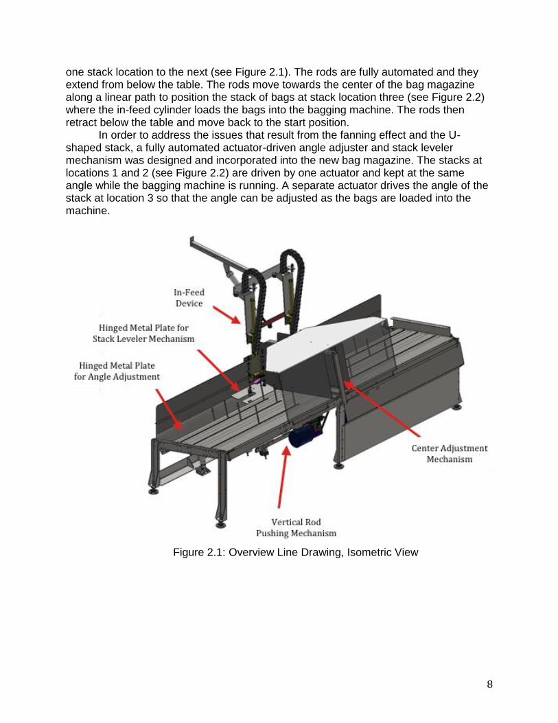
one stack location to the next (see Figure 2.1). The rods are fully automated and they extend from below the table. The rods move towards the center of the bag magazine along a linear path to position the stack of bags at stack location three (see Figure 2.2) where the in-feed cylinder loads the bags into the bagging machine. The rods then retract below the table and move back to the start position.
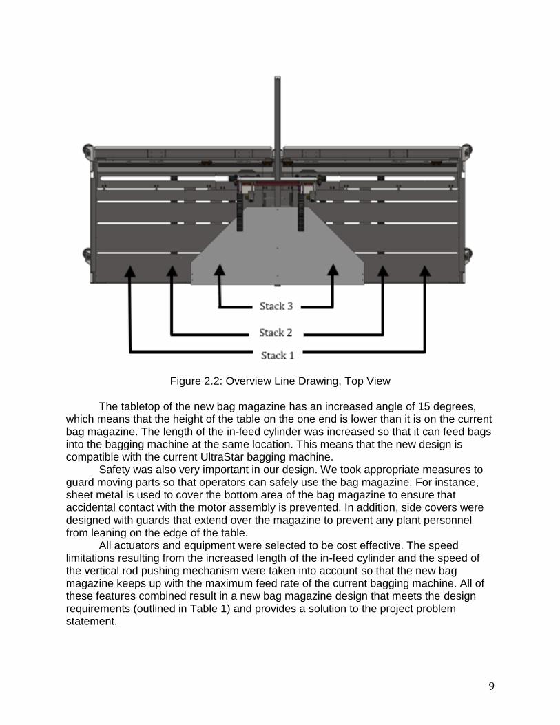
In order to address the issues that result from the fanning effect and the U-shaped stack, a fully automated actuator-driven angle adjuster and stack leveler mechanism was designed and incorporated into the new bag magazine. The stacks at locations 1 and 2 (see Figure 2.2) are driven by one actuator and kept at the same angle while the bagging machine is running. A separate actuator drives the angle of the stack at location 3 so that the angle can be adjusted as the bags are loaded into the machine.
Figure 2.1: Overview Line Drawing, Isometric View
9
Figure 2.2: Overview Line Drawing, Top View
The tabletop of the new bag magazine has an increased angle of 15 degrees,
which means that the height of the table on the one end is lower than it is on the current bag magazine. The length of the in-feed cylinder was increased so that it can feed bags into the bagging machine at the same location. This means that the new design is compatible with the current UltraStar bagging machine.
Safety was also very important in our design. We took appropriate measures to guard moving parts so that operators can safely use the bag magazine. For instance, sheet metal is used to cover the bottom area of the bag magazine to ensure that accidental contact with the motor assembly is prevented. In addition, side covers were designed with guards that extend over the magazine to prevent any plant personnel from leaning on the edge of the table.
All actuators and equipment were selected to be cost effective. The speed limitations resulting from the increased length of the in-feed cylinder and the speed of the vertical rod pushing mechanism were taken into account so that the new bag magazine keeps up with the maximum feed rate of the current bagging machine. All of these features combined result in a new bag magazine design that meets the design requirements (outlined in Table 1) and provides a solution to the project problem statement.

10
2.2 Detailed Description The functional block diagram (Figure 2.3) shows the various functions of the new
bag magazine, and how all of the functions work together. The bag magazine has five main functions: vertical rod pushing mechanism, center adjustment mechanism, longer in-feed cylinder, actuator driven stack leveler mechanism, and actuator driven angle adjustment. These five main functions are described in greater detail in the following sections. Figure 2.4 is a sequence diagram that explains the flow of each step in the operation of the bag magazine.
2.2.1 Functional Block Diagram Figure 2.3 is a functional block diagram of the solution to the design problem.
Figure 2.3: Functional Block Diagram

11
Figure 2.4: Sequence Diagram
2.2.2 Functional Description 2.2.2.1 Vertical Rod Pushing Mechanism
Figure 2.5 shows one of the vertical rod pushing mechanisms on the new bag magazine.
Figure 2.5: Vertical rod pushing mechanism is highlighted in the large red square; the
smaller red squares highlight the cylinder rods that are extended above the table

12
The new bag magazine has vertical pneumatic cylinders that are perpendicular to the tabletop of the bag magazine. Three 200 mm cylinders are distributed along the width of the table that is angled at 15 degrees, and one 150 mm cylinder is located in the adjustable angled section of the table. There are two sets of four cylinders on both sides of the table, for a total of 16 cylinders. A rod connects the four cylinders that span the width of the bag magazine; this set of cylinders is connected to the second set of four cylinders as shown in Figure 2.6.
The cylinders that are used in the design are double rod, double acting cylinders. They were chosen because the double rod cylinder can better withstand side loading. Using this type of cylinder will prolong the life of the cylinder seals when loaded under these conditions.
When stacks of bags need to be moved, the rods extend from below the table. Each set of eight cylinders will be moved toward the center of the bag magazine using a motor and chain system (see Figure 2.8). The cylinder subassembly rides on a set of linear rails. The chain is spliced and the cylinder subassembly is attached to the chain by a custom mounting bracket (see Figure 2.7). Once the bags have been moved, the rods will retract below the tabletop. The motor will move the cylinders back to the start position. The motor will be controlled by feedback from sensors, such as a photo-eye and reflective tape.
Figure 2.6: Cylinder subassembly of vertical rod pushing mechanism, side view (left)
and top view (right)

13
Figure 2.7: Cylinder subassembly in the retracted (left) and extended (right) configurations; the mounting bracket is highlighted in the red square
Figure 2.8: Motor and chain subassembly
2.2.2.2 Center Adjustment Mechanism The center adjustment mechanism controls the position of the center stop wall of
the bag magazine so that different widths of bags will be centered below the suction cups of the in-feed cylinder. The center adjustment mechanism uses actuators to move vertically oriented pieces of sheet metal into position for different bag sizes (see Figures 2.9 and 2.10). The pieces of sheet metal act as a wall stop to help align the bags as they are moved to stack location 3 and pushed up against the wall by the vertical rod pushing mechanism. A photo eye is mounted on the sheet metal wall stop that gives feedback when the stack of bags at location 3 is empty. For safety, a guard is also placed over the mechanism to protect the operator and other factory personnel. The new center adjustment mechanism is taller to accommodate the larger stacks of bags, and it is wider so that it will span the width of the table.

14
Figure 2.9: Center adjustment mechanism
Figure 2.10: Exploded view of center adjustment mechanism
2.2.2.3 In-Feed Cylinder
The in-feed device consists of a cylinder with pneumatic suction cups on the end. The cylinder extends down until it reaches the stack of bags. It picks up one bag from

15
the sealed end using pneumatic suction cups and feeds it into the bagging machine. To ensure that the new design is compatible with the UltraStar bagging machine, the cylinder must retract to the same position as the current design. Because the pick up location on the new bag magazine is lower than the current bag magazine, the in-feed cylinder requires a longer travel distance to reach the surface of the tabletop. Thus, the in-feed cylinder was lengthened by 100 mm to increase the distance it can travel.
Figure 2.11: In-feed device, front view
Figure 2.12: In-feed device, isometric view; the two configurations show the in-feed
cylinder retracted (left) and extended (right)

16
2.2.2.4 Stack Leveler Mechanism The fully automated actuator driven stack leveler mechanism is located at stack
location 3 (see Figure 2.13). The mechanism consists of a hinged plate that is positioned using a pneumatic position control cylinder. The purpose of this mechanism is to ensure that the suction cups on the in-feed cylinder have a flat surface at the point of contact with the bag. If the surface is not flat enough, the suction cups will not be able to obtain enough suction to lift the bag.
Figure 2.13: Location of stack leveler mechanism on bag magazine Initially the metal flap is positioned at the largest angle to account for the
maximum difference in thickness between the sealed and unsealed ends of the stack of bags. As the stack is emptied, the actuator will push on the hinged plate and reduce the angle between the plate and the surface of the tabletop of the bag magazine. This will create a level surface for the suction cups. The range of motion for the hinged plate is 35 degrees below the plane of the table, and 15 degrees above the plane of the table.
Figure 2.14: Actuator driven stack leveler, isometric view

17
2.2.2.5 Angle Adjustment The actuator driven angle adjuster is located at stack locations 1 and 2 (see
Figures 2.15 and 2.16). This hinged plate is moved using the same pneumatic position control cylinders as the stack leveler. The angle of the hinged metal plate will only be adjusted when the bag size or style is changed. This adjustment will be programmed so that the angle is changed using a fully automated process.
Figure 2.15: Location of angle adjustment mechanism on bag magazine
Figure 2.16: Actuator driven angle adjustment, isometric view

18
2.3 Additional Uses The new bag magazine is designed to be used with a bagging machine, so the
only additional uses for the new bag magazine would be in new bagging machines that are developed at Thiele Technologies. The new bag magazine is designed to be compatible with the UltraStar bagging machine. This will be very beneficial to Thiele’s customers because they can purchase the new bag magazine for their current UltraStar bagging machines. 3 Evaluation 3.1 Evaluation Plan
A summary of the top four design requirements and a brief description of the evaluation methods are listed in Table 3.1. Overviews of the evaluation methods are described in more detail below.
Table 3.1: Summary of design requirements and evaluation method
# Design Requirement
Marginal Value
Ideal Value Source Evaluation Method
1 Magazine Capacity
500 bags 1000 bags Customer interviews
Test stack leveler mechanism
2 Footprint <140” Long, <48” Wide
130” Long, 43.6” Wide
Thiele Measure in SolidWorks
3 Unit Manufacturing Cost
< $25,000 < $10,000 Customer interviews
Cost Analysis
4 Bag feed rate 30+ bags/min
30+ bags/min Thiele Calculate feed rate based on speed of
moving parts
Overview of test plan: Magazine Capacity: In order to determine whether or not the design meets the bag magazine capacity requirement, a physical prototype of the stack leveler mechanism was constructed. The purpose of the stack leveler mechanism is to decrease the severity of the fanning effect and the U-shaped stack, which is necessary to achieve the capacity defined by the design requirement. The stack leveler mechanism was tested for poly-woven bags and multiwall paper bags with 40, 80, 120, and 160 bags in the stack. The angled plate was adjusted to angles of 45, 30, 15, 0, and -15 degrees. The results were documented and analyzed. Footprint: The new bag magazine was modeled in SolidWorks. The footprint of the new bag magazine design was measured in SolidWorks.

19
Unit Manufacturing Cost: A bill of materials was created from the SolidWorks model. The estimated price of components (such as motors, cylinders, and actuators) was determined from vendor websites such as www.grainger.com and www.mcmaster.com. Raw material costs were estimated based on information given to us from our project advisor. Custom parts will be cut from sheet metal using a laser-cutting machine. Parts that are cut using the laser are priced based on the number of inches that are cut. For these parts, we measured the perimeter of the parts from the SolidWorks model. We used the information on raw material costs and machining and cutting costs to estimate the total cost of the part. In addition, we received input from our project advisor that validated our estimated cost. Bag Feed Rate: In order to evaluate whether or not the new bag magazine will keep up with the maximum bag feed rate of 30 bags per minute, we calculated the total amount of time between when the in-feed device picks up the last bag in stack location three to when a full stack of bags is incremented to stack location three and ready to be fed into the bagging machine. This calculation was based on the speed of the stack leveler actuator, the speed of the vertical rod pushing mechanism, and the speed of the in-feed cylinder. 3.2 Evaluation Results 3.2.1 Magazine Capacity
The purpose of this test was to determine the feasibility of using stacks of 160 bags by testing a physical prototype of the stack leveler mechanism, combined with a tabletop angle of 15 degrees. The capacity is defined as the total number of bags that can be loaded on the bag magazine. The physical prototype of the stack leveler mechanism was made of wood with a leveling mechanism attached by a piano hinge. The angle of the leveling mechanism was controlled using a drafting table hinge that could be adjusted to 5 discrete angles. Bags were loaded onto the prototype in increments of 40 bags until the maximum capacity of 160 bags was reached. For each stack size, the leveling mechanism was adjusted to angles of 45, 30, 15, 0, and -15 degrees (which is parallel with ground). The results show that the stack leveling mechanism succeeds in leveling the area where the pneumatic suction cups of the in-feed device will pick up the bags. The prototype was able to level a stack of 160 bags for both the poly-woven and multiwall paper bags. This means that the expected capacity is 960 bags, which is four times the current capacity of the bag magazine. Refer to Volume II for a complete lab report on the testing of the physical prototype of the stack leveler mechanism. 3.2.2 Footprint
The footprint of the new bag magazine was measured in SolidWorks. The length of the new bag magazine is 134.25”. The width of the new bag magazine is 47.2”. The dimensions of the current bag magazine, and the ideal values for the footprint, are 130” long and 43.6” wide. So, the length of the new bag magazine was increased by about three percent, and the width of the new bag magazine was increased by about eight

20
percent. The increases in width and length are within the acceptable marginal values from the product design specifications.
3.2.3 Unit Manufacturing Cost
Refer to the Bill of Materials in Appendix E for a detailed cost estimate. The total unit manufacturing cost of the bag magazine is expected to be approximately $18,000, which is less than the design requirement of $25,000.
3.2.4 Bag Feed Rate
The slowest part of the bagging process is currently the amount of time it takes to fill the bags with product, which is about three seconds when running at high speed. The new bag magazine cannot be the bottleneck in the bagging process, so when stack location three is empty, the bag magazine must be able to increment a full stack of bags to stack location three in less than three seconds. The amount of time it takes to complete the process of moving a full stack of bags from the adjacent stack location to stack location three was calculated based on: the speed of the actuator driving the stack leveler mechanism at the in-feed stack location, the amount of time it takes for the cylinder rods to extend, the amount of time it takes for the rods to push the full stack of bags to the in-feed stack location, and the amount of time it takes for the in-feed cylinder to extend and pick up a bag from the full stack (see Volume II for calculation of total time to increment a stack of bags).
The total time to increment a stack of bags is approximately 2.7 seconds, which is less than the maximum permissible time of three seconds. In reality, the vertical cylinder rods will already be extended, so the actual amount of time it takes to increment a stack of bags will be less than 2.7 seconds. Sensors, such as a photo eye and reflective tape, will be implemented to coordinate the timing of each step in the process of moving stacks of bags.
3.2.5 Structural Stability
Our team learned from customer interviews that maintenance technicians often stand on the table as they perform tasks on the bagging machine. For this reason, it was necessary to perform a structural analysis. As a simplification, the worst case loading was analyzed. The deflection of one of the C-channel crossbeams was calculated with a 300-pound point load. This load greatly exceeds any load that a single C-channel cross beam would be expected to support. In reality, the tabletop would distribute an applied load over several beams, so the results are conservative.
The beam was analyzed in ANSYS to determine if it would fail statically under this load (refer to Volume II for results). The node count for the analysis was over 250,000, which should result in mesh independence for the results. The resulting maximum Von Mises equivalent stress was 9,700 pounds per square inch, which was well under the yield stress of over 36,000 pounds per square inch for structural steel. The safety factor was 3.7, which is more than enough of for this product.
The stress concentrations occurred at the mounting locations, so if further strength is desired, the material thickness could be increased in these areas.

21
The total deformation was also looked at to ensure that deformations do not exist that would affect normal operation of the magazine. The maximum deformation was less than 0.016 inches. This is not an amount that warrants further consideration.
The ANSYS results were verified with a hand calculation of the maximum deflection of the beam under the previously described loading conditions. A simple model was constructed as shown in Volume II. The C-channel was modeled as a simple beam with two fixed ends.
The force acting on the center of the beam is the sum of the weight of the center stack of bags and the weight of a person standing on the bag magazine. The distributed load is the weight of the C-channel. The maximum deflection of the beam was calculated to be approximately 4E-5 inches, which is much lower than the industry deflection standard of 0.248 inches maximum deflection for this C-channel.
In reality, the weight of the bags and the person will be distributed among 4 C-channels. Therefore, the results of the structural analysis show that the bag magazine is structurally stable.
3.3 Discussion 3.3.1 Strengths and Weaknesses
One of the strengths of the new bag magazine design is that it at least doubles the capacity of the current bag magazine, and with some bags it will quadruple the capacity. In turn, the increased capacity will double or quadruple the amount of time the machine can run until more bags need to be loaded (see Volume II for calculation of run time).
The increased run time will reduce the operating costs for Thiele’s customers because one operator will be able to operate multiple machines.
Another strength of the design is that it is similar to the current bag magazine. This will minimize the number of new parts for Thiele. In addition, the new bag magazine is compatible with the current bagging machine, which means customers can easily upgrade to the new high capacity bag magazine. The only thing that will need to be changed on the bagging machine is the cylinder on the in-feed device. The person installing the new bag magazine will need to change out the in-feed cylinder to the new cylinder that has longer travel.
Refer to Volume II for an environmental impact statement for the new bag magazine. The main weakness of the new design is that moving parts were added. This means that fatigue failure is possible and proper maintenance will be necessary. In addition, the new bag magazine has areas that are potential safety hazards. For example, there are slots on the surface of the bag magazine that are big enough that a person could insert their finger into the slot. The cylinder rods are below the surface of the bag magazine when they are retracted and when they are extended, they move side to side in the slots. A person could injure their hand if their fingers are in the slot when the rods move or when the rods extend from below the table. The team has worked to address the weaknesses of the new design. Fatigue failure of components can be avoided by following proper maintenance procedures. Guards are used to cover moving components and pinch points in order to optimize the

22
safety of the design and reduce the probability of accidents (refer to Volume II for details on Regulatory and Safety Considerations). 3.3.2 Next Steps
At the end of the project, the team will deliver complete design documentation that includes a SolidWorks CAD model, part drawings, a bill of materials and evaluation results. We will have a meeting at Thiele Technologies to present the new bag magazine design to Thiele engineers and employees, which will provide an opportunity for the team to effectively communicate design details, answer design-related questions, and facilitate discussion with Thiele’s employees about the hand-off plan for the project.
It is recommended that a full-scale prototype be built in order to test and to finalize design details. The team has taken time to research and size vendor components, but Thiele will need to decide whether or not they will use the suggested components in the final design. Sensors will need to be specified and controls will need to be developed for the actuators used in the new bag magazine. The new bag magazine has been modeled in the student version of SolidWorks, but there will be some work needed from Thiele employees to assign Thiele part numbers to new parts and to convert the files from the student version to the professional version of SolidWorks. In addition, manufacturing-grade assembly instructions will need to be created and an operator manual will need to be written.