hierarchically linked extended features for fingerprint
TRANSCRIPT

Hierarchically linked extended
features for fingerprint processing
Dissertation
zur Erlangung des Doktorgrades
der Mathematisch-Naturwissenschaftlichen Fakultaten
der Georg-August-Universitat zu Gottingen
vorgelegt von
Krzysztof Mieloch
aus WrocÃlaw, Polen
Gottingen 2008

D7
Referent: Prof. Dr. Axel Munk
Koreferent: Prof. Dr. Preda Mihailescu
Tag der mundlichen Prufung: 8. Mai 2008

Contents
Abstract 1
Chapter 1. Introduction 3
1.1. Biometric authentication 3
1.2. Fingerprints as biometrics 4
1.3. Fingerprint acquisition 6
1.4. Thesis motivation 7
1.5. Thesis contributions 9
1.6. Thesis outline 10
1.7. Acknowledgements 10
Chapter 2. Entracer - an extended feature extractor 11
2.1. Fingerprint features 11
2.2. Fingerprint structure extraction 12
2.3. Postprocessing 20
2.4. Neighbour information 21
2.5. Features 24
2.6. Fingerprint structure in detail 26
Chapter 3. Preprocessing using extended features 29
3.1. Segmentation 29
3.2. Segmentation using extended features 30
3.3. Low quality regions 33
Chapter 4. Classification 37
4.1. Introduction 37
4.2. Classification 38
4.3. Extended lines 39
4.4. First decisions 41
iii

iv Contents
4.5. Additional features 43
4.6. Final decisions 46
4.7. Results and conclusion 46
Chapter 5. Matching 51
5.1. Introduction 51
5.2. Measuring the performance of a fingerprint-based identification system 53
5.3. Minutiae-based matching 54
5.4. Consistency-based matching 55
5.5. Extended features-based matching 56
Chapter 6. Development process and software environment 65
6.1. Design and development 65
6.2. Software environment for research and development 66
Chapter 7. Conclusion 69
Bibliography 71
Curriculum Vitae 75

Abstract
This thesis discusses a novel approach for fingerprint feature extraction. A new fingerprintstructure has been proposed as a basis for the extraction of extended features. These newfeatures provide us with a link between the global and local zoom-levels generally utilisedseparately, which can contribute to bridging the gap between the automatic procedure forfingerprint recognition and that of a human expert. Furthermore, a novel developmentprocess based on interactive testing has been proposed. The results of an application ofthe new features in matching and classification confirm the goodness of the features.
1


Chapter 1
Introduction
1.1. Biometric authentication
Nowadays, the identification of a person is a fundamental task for many applications suchas access control, authorised users authentication, or credit card transactions. A personmay be identified based on her possessions, e.g. a key, or her knowledge of a piece ofinformation, e.g. a pin or password. However, a token such as a physical key or a smartcard can be lost, stolen, duplicated or left at home, while a password can be forgotten,shared or compromised. Furthermore, since we live in a rapidly developing, electronicworld we are obliged to remember a multitude of passwords and personal identificationnumbers for computer accounts, cash dispensers, e-mail accounts, mobile phones and soforth. Consequently, alternative authentication methods based on identifying physicalcharacteristics of a person have been developed. Such characteristics are:
• physiological traits, e.g. fingerprints, face, hand geometry;
• behavioural characteristics, e.g. voice, signature, gait.
A method of identification of a person based on her distinctive physiological or behaviouralcharacteristics is called biometrics [1].
A significant difference between a biometrics-based person identification and other,conventional methods is that the conventional methods do not involve any complex patternrecognition and hence they almost always perform accurately as intended by their systemdesigners. A conventional method provides us with a clear answer if a person is who heclaims to be, whereas a biometric system provides us only with a similarity score. Hence atypical biometrics-based system is not perfectly accurate and basically commits two typesof errors: a false accept refers to identifying an impostor to be a genuine user and a falsereject refers to rejecting a genuine user as an impostor [2]. Whereas the false reject leadsto inconvenience for users, a false acceptance provides the access to a non-authorised user.
As biometric based identification methods are becoming more popular, big privacyconcerns arise. A part of one’s very personal information is stored in a database. Inopposition to passwords which are usually stored encoded with a one-way function, due tointra-user variability in the acquired biometric traits, ensuring the security of the templatewhile maintaining the recognition performance is a challenging task [3].
3

4 1. Introduction
Figure 1.1. Fingerprint feature levels [6]
1.2. Fingerprints as biometrics
Among various biometric techniques, fingerprint recognition is the most popular one forautomatic person identification [4]. The fingerprint of an individual is unique, so that evenidentical twins have different fingerprints [5]. Furthermore, the structure of fingerprintshardly changes over a lifetime.
A fingerprint is a pattern of ridges and valleys on the surface of a fingertip [4]. Two im-prints are matched by comparison of characteristic features which are generally categorisedinto three levels [6] (Fig. 1.1):
• level 1 features (patterns) - macro details of a fingerprint such as ridge flowand pattern type which are used for fingerprint classification, global level;
• level 2 features (points) - minutiae, which have sufficient discriminating powerto establish the individuality of fingerprints, local level;
• level 3 features (shapes) - all dimensional attributes of a ridge such as ridgepath deviation, width, shape, sweat pores, edge contour, incipient ridges, breaks,creases, scars and other permanent details, intermediate level between global andlocal level.
The tasks in fingerprint recognition are generally categorised into four groups:
• Fingerprint image preprocessing: preparation of an acquired fingerprint im-age for further processing. This step contains image processing algorithms suchas image enhancement or discrimination between the foreground containing thefingerprint and the background. For an example of a fingerprint image beforeand after preprocessing see Fig. 1.5(a) and 1.5(b).

1.2. Fingerprints as biometrics 5
(a) correlation-based (b) minutiae-based (c) ridge feature-based
Figure 1.2. Three approaches to fingerprint matching [8]
• Fingerprint feature extraction: although there exist correlation-based meth-ods for fingerprint matching which compare images directly, gray-scale imageintensities are known to be unstable representations of fingerprints. Most of thefingerprint recognition algorithms are feature-based [7].
• Matching: comparison of two given fingerprints providing a degree of similarity.A large number of approaches can be classified into three families [7]:
– correlation-based matching (Fig. 1.2(a)): two fingerprint images are super-imposed and the correlation between corresponding pixels is computed fordifferent alignments.
– minutiae-based matching (Fig. 1.2(b)): most popular and widely used tech-nique based on finding the alignment between two minutiae sets, resultingin the maximum number of minutiae pairings.
– ridge feature-based matching (Fig. 1.2(c)): the approaches belonging to thisfamily compare fingerprints in terms of features extracted from ridge patternssuch as local orientation and frequency, ridge shape or texture information.
• Classification: in order to identify a person, her fingerprint has to be comparedwith each fingerprint in a database. In case of a large database the identificationtypically has an unacceptably long response time. A common strategy to speedup the query is to narrow the search by dividing the fingerprint database intoa number of bins (based on some predefined classes). A given fingerprint tobe identified is then compared only to the fingerprints in a single bin. Themost important and widely used classification schemes are variants of Henry’sclassification scheme [7]. The six most common classes, naturally defined bythe pattern flow, are presented in Fig. 1.3. Unfortunately fingerprints are notuniformly distributed among these six classes:
plain arch tented arch left loop right loop whorl double loop
3.7% 2.9% 33.8% 31.7% 23.1% 4.8%
Hence, for applications which do not require compliance with an existing classi-fication scheme, other indexing methods have been proposed. In indexing (i.e.continuous classification), fingerprints are not partitioned into disjoint classes,but associated with a point in a normed vector space so that similar fingerprintsare mapped to close points. During the identification process the input finger-print is matched with those in the database whose corresponding vectors are closeto the searched one [9].

6 1. Introduction
(a) plain arch (b) tended arch (c) whorl
(d) left loop (e) right loop (f) double loop
Figure 1.3. The widespread Henry’s classification scheme
1.3. Fingerprint acquisition
The traditional way of capturing a fingerprint is inking, in which black ink is spread onthe finger which is then pressed against a paper card; afterwards the card is scanned witha common paper-scanner [7] (a sample of an inked fingerprint is presented in Fig. 1.4(a)).Inking has a long tradition and is still used in some law enforcement applications [10].However, this method is unsuitable for security systems in which online acquisition isrequired and hence, live-scan devices must be employed. There are a lot of scanner typesavailable on the market; the most common ones are listed below:
• optical (Fig. 1.4(b)) – the image is captured by a CCD (charged coupled device)or a CMOS (complementary metal oxide semiconductor) camera. In general, thefinger is placed on a glass plate and the camera takes a picture. A disadvantageof an optical system is its vulnerability, that is, the sensor cannot distinguishwhether the presented finger is real or a fake. Another problem is related tolatent fingerprints left by a finger previously placed on the sensor surface.
• capacitive (Fig. 1.4(c)) – the most popular one. A capacitive sensor with elec-trical current is employed for measuring the fingerprint. The main advantages ofcapacitive sensors are low-cost and built-in liveness detection. However, capacit-ive sensors have problems with fingerprints from wet or dry fingers.
• surface pressure sensor – the principle of pressure sensing is as follows: when afinger is placed on the sensor area only the ridges of the fingerprint touch thesensor’s piezo array. In contrast, the valleys have no contact with the sensor cells.
• touchless (Fig. 1.4(d)) – in all sensor types mentioned above, a finger has tobe pressed onto the sensor surface, which can introduce non-linear distortions(for details see Section 5.1). A solution to this problem is a touchless fingerprintsensor technique which is currently under development. With touchless sensors,the finger is not placed on a surface but only held over the sensor at about 5 cm.A disadvantage is that dust and dirt between the sensor and the fingerprint maycontribute to bad quality of the images.

1.4. Thesis motivation 7
(a) inked fingerprint (b) optical-typesensor
(c) capacitive-type sensor (d) touchless sensor
Figure 1.4. Sample fingerprint impressions acquired with help of different methods
1.4. Thesis motivation
As a consequence of the requirements of law enforcement and interest on the part ofthe developers of biometric systems, efficient fingerprint-based identification systems arebecoming rapidly widespread, and are extensively researched by the pattern recognitioncommunity. It is a common misconception that automated fingerprint identification is asolved problem: despite significant research efforts over the past four decades, the stateof the art in fingerprint matching technology is nowhere near the theoretically possibleperformance [11].
The general framework for fingerprint identification systems is well-established in theliterature. A majority of current publications accepts this framework, and attempts aremade to improve specific algorithms at various levels of processing. This approach hasbeneficial effects as the minor improvements contribute to higher accuracies. However, asthe state of the art is still far from its theoretical potential, approaches radically differentfrom those currently in fashion appear to be worth exploring [12].
Most fingerprint matching algorithms are based on matching small fingerprint detailsknown as minutiae. However, minutiae are only a small subset of all the informationcontained in a fingerprint. Consequently, while comparing two imprints, experts do notfocus exclusively on minutiae, taking among others the level 3 features as well as unusualformations of the fingerprint lines into account and viewing fingerprint image at bothglobal and local scales at the same time. As a result, though the information contained inminutiae is sufficient for automatic recognition of fingerprint images unaffected by noisebecause a sufficient number of genuine minutiae can be extracted, it is not reliable enoughfor disturbed images. There, in order to improve the recognition, non-minutiae-basedinformation present in fingerprints should be explored.
Requirements for identifying and defining additional fingerprint features beyond minu-tiae, even not limited to level 3 details, has already been addressed by the community [13].However, new feature proposals are based on refinements of existing features (e.g. a finerlevel of classification), or on the introduction of new single features (e.g. 3-D level featuressuch as the ridge height) [14]. The new set of features proposed in this work does not onlyinclude additional fingerprint features individually but it also contains the informationabout their relationships such as line adjacency information at minutiae points or linksbetween neighbouring fingerprint lines.

8 1. Introduction
As has already been mentioned, an expert can look at a fingerprint image at variousscales at the same time, whereas common automatic methods utilise different feature levelsseparately in different fingerprint processing steps. Thus the concept put forward in thisthesis is to extract a universal set of features which can be used in all the tasks of fingerprintprocessing. As a consequence, the time required for extraction, and the space demandedfor storing those features might be reduced. An example of such a universal feature ispresented in Fig. 1.5(e). The extracted red line provides us with both information aboutthe class of the imprint (left loop) and part of the information for matching, since theset of all such lines allows us to discriminate between fingerprints deriving from differentfingers, whereas the commonly used features for classification, such as orientation fields orsingular points, do not provide enough discriminating information for matching. Moreover,the utilisation of local information can decrease the misclassification rate as explained inChapter 4.
In spite of the fact that a fingerprint is a structure build up from both ridges andvalleys, common algorithms extract information only from ridges. At first sight, it appearsto be reasonable as the processing of both ridges and valleys would be redundant. On theother hand, the apparent redundancy provides us with information which can be used tocorrect defects caused by noise. If either one is disturbed by noise, the other one maybe correct and may allow to correct the first one. In Fig. 1.5(a) the ridges (dark lines)are disconnected due to a dry fingertip skin. Nonetheless, since fingerprint lines changetheir direction rather smoothly, the valleys can be extracted properly and then be usedfor connecting the ridges. Such errors might also be removed with image processing tools.A directional smoothing filter, such as the Gabor filter [15], results in an enhancement ofdisconnected lines as presented in Fig. 1.5(b). Unfortunately, at the same time some level3 features, e.g. scars, might also be smoothed out as shown in Fig. 1.5(c) and 1.5(d).
Assessing both ridges and valleys allows to validate the extracted information by theduality principle: a bifurcation of ridge corresponds to an ending of valley and vice versa.The green ending of the ridge in Fig. 1.5(f) corresponds to the blue bifurcation of thevalley. The only exception to this principle arises in singular areas, as shown in Fig.1.5(f): the red marked ending in the core area does not posses a corresponding minutia.There exists exactly one such minutia for each singular point. Consequently, minutiaewithout corresponding dual minutia outside the singular areas are indicators for errors inacquisition, preprocessing or feature extraction in that region. Thus the region can bemarked and processed again more thoroughly.
In order to improve the matching, it is vital that the extracted features set remainsstable over multiple acquisitions. However, even if a feature is missing in one impres-sion, the extracted structure around the missing feature ideally should provide enoughinformation to confirm the fact of the existence of that feature in the original fingerprint.
Another important challenge is the reduction of the space required for storing acquiredfingerprint impressions. Let it suffice to say that the FBI databases already contain over200 million fingerprint records [7] and as the number of records is growing rapidly, therequirements on storage are similarly increasing. Consequently it is crucial to find a low-memory representation for a fingerprint containing all necessary information.
To summarise, the guiding principle of this thesis might be expressed as:
Extract a maximal amount of stable information robustly.

1.5. Thesis contributions 9
(a) A noisy fingerprint im-age with disturbed lines
(b) The disturbed linesafter a preprocessing step
(c) A fingerprint withscars
(d) The scars after a pre-processing step
(e) Local feature for clas-sification
(f) Duality principle
Figure 1.5.
1.5. Thesis contributions
The presented work contributes to various stages of the fingerprint recognition process. Abrief summary of the specific contributions is listed below:
• In order to bridge the gap between automatic procedures and human experts, anew class of fingerprint features which combine the traditional global and localfeatures, is in this thesis.
• A is novel low-memory representation of fingerprints is proposed as a basis forextracting of these new features.
• Additional information contained in a fingerprint, such as duality between ridgesand valleys, is utilised to obtain a reliable feature set.
• Two improvements to the preprocessing stage are made, resulting in better seg-mentation, and enhancement of areas disturbed by noise.
• A novel approach to fingerprint classification based on the extracted features isproposed, as a result the misclassification error rate has been decreased by 0.2%to 3.5%.
• For the first confirmation of the quality of extracted features in application for thematching, the precision of the extracted minutiae is measured. The experimentsshow a decreased error rate when supplying the minutiae to a standard minutiae-based matcher.
• A broad and careful study of the extracted features for fingerprint matchingis conducted with the objective to develop a matcher which fully utilises theadvantages of all those features.
• A novel development process based on interactive testing is proposed. As aconsequence, an interactive software environment for fingerprint research has beencreated.

10 1. Introduction
1.6. Thesis outline
This thesis starts in Chapter 2 with the description of a new approach for fingerprintfeature extraction. Following chapters discuss the application of the extracted featuresto different stages of fingerprint recognition. Chapter 3 addresses preprocessing, Chapter4 presents classification, followed by matching in Chapter 5. The development processand interactive software environment for fingerprint research is presented in Chapter 6.Finally, Chapter 7 contains a summary of the major contributions and results of the thesis,and puts forward suggestions for future research in this direction.
1.7. Acknowledgements
This work would not be possible without the help of many people. I wish to thank mythesis advisor Axel Munk for proposing the problem and supervision. My thanks go alsoto my coadvisor Preda Mihailescu for fruitful discussions and drawing my attention to newtopics in fingerprint recognition field. I would like to thank the Institute for MathematicalStochastics at the University of Gottingen and the DFG’s Graduiertenkolleg “Identifikationin mathematischen Modellen: Synergie stochastischer und numerischer Methoden” for thefinancial and scientific support. I would like to thank Thomas Hotz for proof-reading thisthesis from which it benefited greatly. Last but not least I want to thank my colleaguesat the institute for discussions and the general good working atmosphere.

Chapter 2
Entracer - an extended
feature extractor
2.1. Fingerprint features
The ways a forensic expert and a machine treat a fingerprint image (Fig. 2.1(a)) differ inmany aspects. A machine utilises the different levels separately for different applications:for classification the global level (Fig. 2.1(b)) is used, whereas for matching exclusivelylocal features (Fig. 2.1(c)) are used, and the global information is not used directly. Anexpert, however, approaches a fingerprint impression at different scales at the same time.
Furthermore, the most common matching algorithms use only level 2 features and nolevel 3 features (Fig. 2.1(d)), although they – like the level 2 features, are also claimed tobe permanent, immutable, and unique [1]. If properly utilised, they can provide discrim-inatory information, and that is why forensic experts use them together with the level 2features in a latent print examination.
One reason why level 3 features are hardly used by commercial software is that for anautomatic extraction of most of those features high resolution (at least 1000 dpi) devicesare required [1]. However, some of the features (such as a ridge shape, breaks, creases) canalso be easily found in images acquired by 500 dpi scanners which are commonly used inautomatic systems. In this section we will define such features and describe an extractionmethod for them. Since we will also extract additional features (such as ridge connectioninformation or neighbourhood information) we propose to call them hierarchically linkedextended features.
Our data extraction approach differs from other current approaches in more thanone aspect. We tackle the problems of orientation flow extraction, ridge and minutiaerecognition at the same time, taking advantage of their interdependence. The features areextracted by following the fingerprint lines. In doing so, we use a simple adaptive - orentropy sensitive - approach. Its two main characteristics give the name to our method:entropy sensitive tracer - entracer.
11

12 2. Entracer - an extended feature extractor
(a) Sample fingerprint image (b) Global features - level 1 features
bifurcationending
(c) Local features - level 2 features
sweat porescrease
(d) Local level 3 features
Figure 2.1. Different zoom-levels at which a fingerprint image can be viewed
2.2. Fingerprint structure extraction
In order to identify fingerprint features, first a fingerprint structure containing the finger-print’s crucial information has to be extracted. The essential engine which we are goingto use for that task is a fingerprint line tracer. Various approaches for minutia detectionwhich are based on following lines have been investigated in the literature [16; 17; 18; 19].However, there are principial differences between the existing methods and ours:
• We additionally extract the so-called extended features, whereas other approachesfocus solely on minutiae detection.

2.2. Fingerprint structure extraction 13
(a) (b)
Figure 2.2. A fingerprint (a) and its orientation field (b).
• We perform the tracing in an already binarised image. In contrast to grey levelimages, in binarised images recognising the line’s border while following it is muchsimpler and faster. Thus we can skip the costly centring on the line but on theother hand we have to binarise the input image. Still, it is advantageous sincebinarisation is much faster than centring. Furthermore, we do not fully dismissthe grey level image, but come back to it if necessary; for example in regionswhere the binarised image is strongly disturbed by noise.
• Both ridge and valley lines (or simply the white and black lines) are processed.The objective of the apparently redundant information is the correction of de-fects caused by noise. For example, in regions where black lines are broken theinformation from connected white lines is used to repair the black lines.
• We do not need to compute the orientation field1 before tracing. Moreover, theorientation field can easily be computed from the extracted features.
2.2.1. Preprocessing. Before we can apply the tracer algorithm to an acquired finger-print image, some preprocessing steps on the image have to be performed.
Since common matching algorithms utilise only level 1 and 2 features, the additionalfeatures are treated as noise and are removed during the enhancement stage. The ap-plication of a directional smoothing filter results in an enhancement of the input image.A widespread smoothing method is based on Gabor filters [15]. As already mentioned,fingerprints are flow-like patterns which consist of locally parallel ridges and valleys, andtheir local frequency and orientation are well defined. Gabor filters have both frequency-and orientation-selective properties and have a good joint resolution in both spatial andfrequency domains. Hence, Gabor filters are sensibly used to remove the noise and preservetrue ridge/valley structures [20].
1The orientation field is the set of local ridge orientations as illustrated in Fig. 2.2.

14 2. Entracer - an extended feature extractor
−15−10
−50
510
15
−15−10
−50
510
15−0.8
−0.6
−0.4
−0.2
0
0.2
0.4
0.6
0.8
1
xy
Figure 2.3. Graphical representation of the Gabor filter.
As shown in Fig. 2.3, the Gabor filter is defined by a cosinusoidal plane wave tapered bya Gaussian. The even symmetric two-dimensional Gabor filter has the following form [7]:
G(x, y; θ, f) = exp
(−
1
2
(x2
θ
σ2x
+y2
θ
σ2y
))· cos (2πfxθ)
xθ = x sin θ + y cos θ
yθ = y cos θ − x sin θ
where θ is the orientation of the Gabor filter, f is the frequency of the cosinusoidal planeand σx and σy are the standard deviations of the Gaussian envelope along the x− andy−axes, respectively.
To apply Gabor filters to an image, each pixel (x, y) of an image is convolved, in thespatial domain, with the filter G(x, y; θ, f) such that θ is the ridge orientation at the pixeland f its ridge frequency. An example of the application of Gabor filters to a fingerprintis presented in Fig. 2.4. Whereas the disrupted ridges have been connected (Fig. 2.4(a)and 2.4(b)), the level 3 features (Fig. 2.4(c) and 2.4(d)) are smoothed out simultaneously.In order to preserve the information about the level 3 features, we use a very weaklysmoothing Gabor filter and additional non-directional smoothing enhancement, such asholes filling and a median filter.
Segmentation2, that is, the division between the foreground containing information andthe background, is very important for our line following algorithm since only fingerprintlines and not the surrounding area should be traced. We apply the algorithm proposedby Bazen and Garez [21] for this task.
Finally, the image is binarised by means of the common adaptive mean filtering [7].
2For a detailed description of segmentation see Section 3.1.
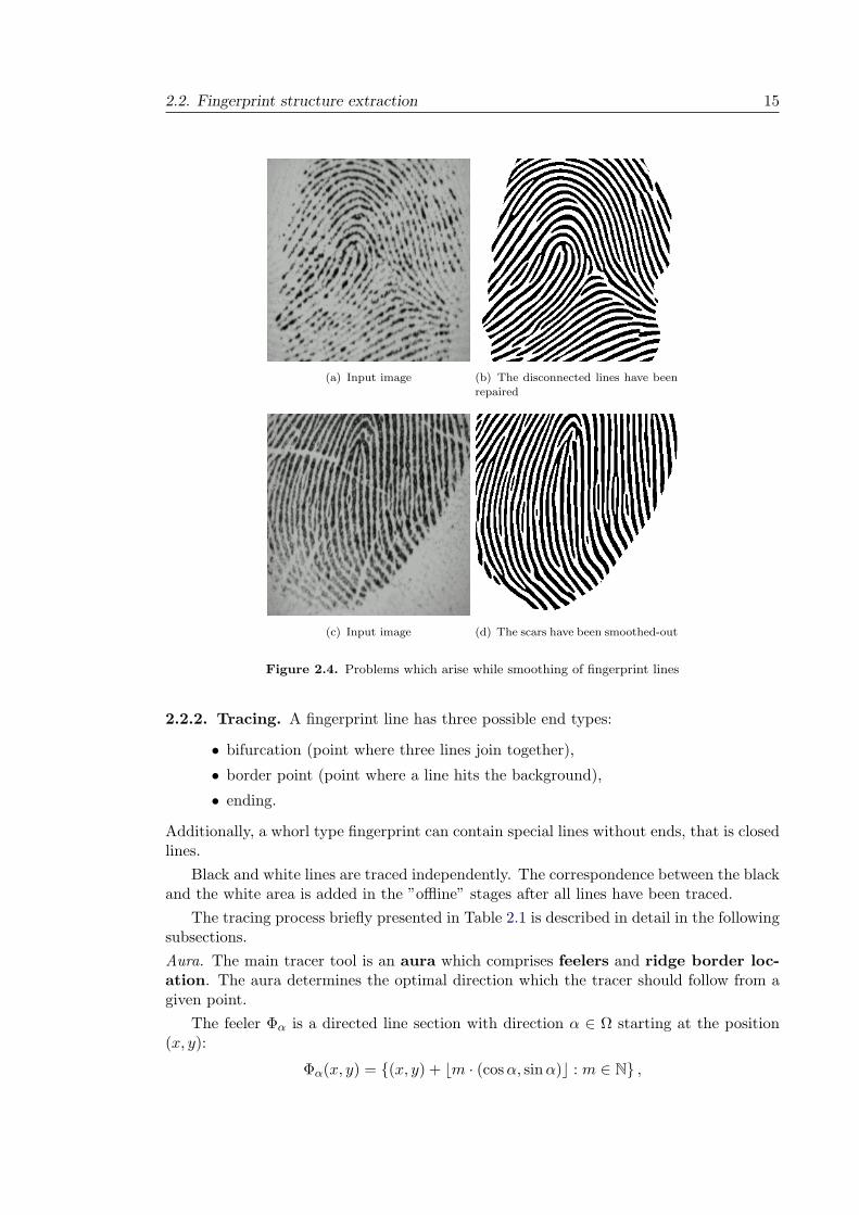
2.2. Fingerprint structure extraction 15
(a) Input image (b) The disconnected lines have beenrepaired
(c) Input image (d) The scars have been smoothed-out
Figure 2.4. Problems which arise while smoothing of fingerprint lines
2.2.2. Tracing. A fingerprint line has three possible end types:
• bifurcation (point where three lines join together),
• border point (point where a line hits the background),
• ending.
Additionally, a whorl type fingerprint can contain special lines without ends, that is closedlines.
Black and white lines are traced independently. The correspondence between the blackand the white area is added in the ”offline” stages after all lines have been traced.
The tracing process briefly presented in Table 2.1 is described in detail in the followingsubsections.
Aura. The main tracer tool is an aura which comprises feelers and ridge border loc-ation. The aura determines the optimal direction which the tracer should follow from agiven point.
The feeler Φα is a directed line section with direction α ∈ Ω starting at the position(x, y):
Φα(x, y) = (x, y) + ⌊m · (cos α, sin α)⌋ : m ∈ N ,

16 2. Entracer - an extended feature extractor
Table 2.1. Tracing process
begin
found newvalid starting point? end
start a new segment
full directional aurarestricted
directional aura
go to the
furthest point
add the point
to the segment
hit a traced line?
did the segment
met itself? hit the border?
an ending?
whorlhandling
bifurcationhandling
marka border point
markan ending point
yesno
yesno
yes no yes
no
yes
no
(x,y)
α(x,y)
Φα
αB (x,y)
l (x,y)α
(a) Sample values of functions for auracomputation
(b) Set of angular border distances.
Figure 2.5.
For each direction α the maximal value of m is computed, such that the section Φα(x, y)stays within the fingerprint line. The section length for that m is computed as:
lα(x, y) = |Bα(x, y) − (x, y)| ,
where Bα(x, y) : N2 → N
2 returns the point where the section Φα(x, y) crosses the lineborder and | · | denotes the Euclidian distance, see Fig. 2.5.

2.2. Fingerprint structure extraction 17
(a) (b)
Figure 2.6. Aura in a starting point (a) and in a next point (b).
The set of directions Ω at the first point of the traced line is a discrete set of equidistantangles:
Ω =
i
n2π : i = 0, ..., n − 1
As ridges and valleys do not take abrupt turns but change direction rather smoothly, wecan restrict Ω to some subset Ω0 ⊂ Ω for the following points on the line so that onlydirections in a cone around the previous direction are taken into account. An example isshown in Fig. 2.6. An extracted fingerprint line between two minutiae or border pointswill be called a segment.
Valid starting point. A point in a fingerprint image at which a single tracing process isstarted has to fulfil the following conditions:
• it is located in the foreground,
• it is within a fingerprint line,
• the line has not been traced yet.
In order to check the last two conditions, the full aura is computed for a given point.It has to have significantly larger values for two opposite directions compared with theirorthogonal directions, and none of the feelers should meet an already traced line at adistance below a given threshold.
The candidates for the starting points are taken from a grid, that is from the set
(i · x∆, j · y∆) : i = 1 . . .
⌊xsize
x∆
⌋, j = 1 . . .
⌊ysize
y∆
⌋
where xsize and ysize are the vertical and horizontal size of the input fingerprint imagewhile the values of x∆ and y∆ depend on the resolution of the fingerprint sensor wasused for acquisition. On the one hand, overly small values result in unnecessarily largecomputation times for processing the whole fingerprint. On the other hand, if the valuesare too large some lines may not be traced. For a 500 dpi sensor, we choose x∆ = y∆ = 4.
The tests performed have shown that the order in which the points on the grid areexamined does not influence the result of the tracing.
Branches of a bifurcation. In order to properly identify the segments connected to a bi-furcation, adjacent segments are numbered according to a certain scheme: the first branchis the one on the opposite side of the smallest angle and all branches are ordered anti-clockwise (Fig. 2.7(a)).
To find the correct order, the distances a, b, c (Fig. 2.7(b)) between the points on theconnected segments at a given distance from the bifurcation point are computed. Thesmallest distance (in this case c) is between the second and the third branch.

18 2. Entracer - an extended feature extractor
31
2(a)
a
b
c
(b)
Figure 2.7. The order of bifurcation branches
last point new point traced point
Figure 2.8. Simple centring
2.2.2.1. Centring. With the existing grey level tracing methods, in order to follow a ridgecorrectly the tracer has to stay at the top of the ridge, which requires the application of anexpensive centring method. This is not necessary in case of tracing in a binarised imageas the algorithm for line border recognition uses only transitions between the black andthe white area, but no grey level intensity differences. However, if one prefers that thetraced points are near the line centre, a simple and efficient centring can be used. Afterproceeding to the next traced point, the traced point is moved back toward the last pointby 20% of the distance between the current and the last point. An example is presentedin Fig. 2.8.
2.2.3. Fingerprint structure. The information obtained from the tracing process is:
• minutiae and border points;
• closed segments (whorls) which are usually not captured by a typical minutiaeextraction algorithm;
• ordinary segments with two ends from which one is called front end and the otherback end.
Information stored for a minutia or a border point:
• position
• adjacent segments (3 for a bifurcation and 1 for an ending or a border point)with information whether the minutia is connected at the front or back end ofthe segment.
The following data are stored for segments:
• type (simple or closed)
• in case of a simple segment: minutiae or border points at both ends of the segment
• line course as a sequence of points.
A sample traced fingerprint is presented in Fig. 2.9.

2.2. Fingerprint structure extraction 19
(a) Fingerprint structure with underlying binarised image. Each segment is marked with a differentcolour. Endings are marked in green and bifurcations in red. Note the unvalidated minutiae at the core
points where only endings and no bifurcation are marked and and at the delta point where a bifurcationbut no ending is marked.
(b) Fingerprint structure for the black lines. Each segment is marked with a different colour. Endingsare marked in green and bifurcations in red. The black points on the segments are the traced points.
Figure 2.9. A sample traced fingerprint.

20 2. Entracer - an extended feature extractor
2
14
3
(a)
2
14
3
(b)
2
14
3
(c)
Figure 2.10. Deleting of short segments
(a) A bifurcation in white with the correspondingending in black
(b) The exceptionfor a singular point
Figure 2.11. Duality principle
2.3. Postprocessing
Due to existing noise in fingerprint impressions as well as the specific way in which theentracer works, the obtained structure has to be postprocessed.
2.3.1. Short segments. Spurious bifurcations extracted by the entracer in noisy areasare removed in this step. If two bifurcations are connected over a short segment and thesegment is connected to both minutiae at the branch with the same number (Fig. 2.10(a)and 2.10(b)), the short segment and the bifurcations are removed and the remainingsegments are connected (Fig. 2.10(c)). The two segments on the disrupted black line areconnected in one of the later postprocessing stages.
2.3.2. Validation. The white and black areas are naturally dual to each other (see Fig.2.11(a)). Generally, bifurcations in one area correspond bijectively to endings in the otherarea. Natural exceptions can be encountered only at singular points (Fig. 2.11(b)); furtherexceptions are consequences of noise (Fig. 2.12(a) and 2.12(b)) or additional features (Fig.2.12(c)) and thus the existence of dual minutiae is an indicator for a reliable minutia point.Consequently, this – obviously not novel ([7], p.86) – observation of the duality of ridgesand valleys becomes a fruitful resource for validating minutiae.
During the validation step, for every bifurcation its corresponding ending is searchedfor in the area between the second and third branch of the bifurcation, as shown in Fig.2.13. Once the dual ending has been found, the bifurcation position is reset to the endingposition. This eliminates the problem of false positions of bifurcations determined duringthe tracing step. For each validated minutia, the pointer to the corresponding minutia isstored in the structure, which introduces the first connection between dual areas.
2.3.3. “Bifurcations ladder”. It may happen in some fingerprints that due to an un-usual grey-level distribution the background may be falsely recognised as foreground, whichresults in a foreground stripe around the fingerprint (Fig. 2.14(a)). During the tracingprocess false bifurcations are found in such regions (Fig. 2.14(b)). As the bifurcations areconnected between the first and the second or third branch, they are not removed during

2.4. Neighbour information 21
(a) Due to noise, two unval-idated endings have been ex-tracted
(b) Correction of the situ-ation presented in (a)
(c) Crease which is markedas an additional feature formatching
Figure 2.12. Unnatural exceptions from the duality principle
Figure 2.13. Process of minutia validation
(a) Wrongly extractedforeground
(b) Spurious bifurca-tions
(c) Result of the post-processing
Figure 2.14. An example of “bifurcation ladder” processing. For better illustrationonly lines traced in white are shown.
the short segment removal stage but in an extra postprocessing step in which such a se-quence of at least 3 shortly connected bifurcations (which we call bifurcations ladder)is identified and removed. The bifurcations are resolved and the corresponding dual falseendings are changed into border points. The result is shown in Fig. 2.14(c).
2.4. Neighbour information
In order to provide for the required robustness of the features, additional informationcontained in the fingerprint structure must be evaluated. The most important informationfor that purpose is the neighbourhood information described in this section.

22 2. Entracer - an extended feature extractor
BA
C
35
24
1
At point C line 4: At point A line 5: At point A line 5:side: right
position: 25
before: 2
after: 1minutia: B
side: left
position: 0
before: none
after: 3minutia: none
side: right
position: 0
before: none
after: 2minutia: none
Figure 2.15. Sample change points for segment neighbours, front ends of segments 4and 5 are on their right.
2.4.1. Segment neighbours. For further postprocessing and applications to other fin-gerprints tasks (classification, matching), neighbouring dual lines, which are the linesrunning parallel in the dual colour area, are identified for each traced line or, in case ofan outermost segment, the background is marked as the neighbour.
The neighbour information is stored as a list of change points - the points on a linewhere the neighbours change. The information stored in one list element is:
• side of change - right or left looking from the front towards the back end of thesegment;
• position of change - the length of the segment between the front end and thechange point;
• neighbouring segment towards the front end (before);
• neighbouring segment towards the back end (after);
• minutia causing the change of the neighbour.
Some examples for the stored information are shown in Fig. 2.15.
For sake of simplicity, in the following description we assume that minutiae are adjacentat the corresponding segment’s front ends.
Clearly, in a non-disturbed area the neighbour of a segment changes only if there isa minutia on the neighbouring segment. Hence, it suffices to find the neighbours for allminutiae and border points and in order to create the neighbour lists. Consequently,the computation time is reduced in comparison to identifying neighbours by followingsegments and checking at fixed lengths.
The points are processed in the following order:
• validated bifurcations
• border points
• unvalidated minutiae
For a validated bifurcation the information about inside neighbours already exists dueto the duality principle (compare Fig. 2.16(a)). Consequently, the right neighbour of thesecond branch and the left neighbour of the third branch is the segment connected to thedual ending. Hence the neighbours of the segment connected to the ending are definedas well. In order to find the outside neighbours, we follow the directions orthogonal to

2.4. Neighbour information 23
outside
inside
outside
12
3
(a) (b)
Figure 2.16. Finding neighbours for a bifurcation (a) and a border point (b)
A
BC
Figure 2.17. An unvalidated ending next to the background
the bifurcation direction until a segment in the dual area is met. For border points andunvalidated minutiae the strategy is similar to the one for “outside” neighbours at abifurcation. We look for the neighbours in the directions orthogonal to a border point oran unvalidated minutia direction (Fig. 2.16(b)).
2.4.2. Neighbours at border points and unvalidated endings. In addition to theinformation about segment neighbours, the neighbour point (if one exists) is stored foreach unvalidated ending or border point. For the situation presented in Fig. 2.17 at theborder point B the following data is stored: the left neighbour is the border point C andthe right neighbour is the unvalidated ending A.
2.4.3. Postprocessing using neighbours information.
Bridging. For connecting disconnected lines dual information is used. Generally, if a ridgeis disconnected, their dual neighbours are not broken. See Fig. 2.10(c). We use thisinformation to repair broken ridges.
In order to distinguish between a line break caused only by noise and that contained ina fingerprint (creases, scars), the number of neighbouring, disconnected lines is counted. Ifit is less than or equal 3, we treat it as noise and consequently connect the lines. Otherwisethe disconnection is marked as a scar for further processing.
Correcting unvalidated endings. As already mentioned, an unvalidated minutia, apart fromone for each singular point, is an indicator for an extraction error. The neighbour inform-ation can be used to repair such errors.
If an unvalidated ending has a border point as its minutia neighbour (compare Fig.2.17), its type is changed from ending to border point.
Another unvalidated ending occurs when the tracer gets stuck instead of finding abifurcation as presented in Fig. 2.18(a). In order to find and correct these errors, theneighbourhood information can be used and the segment adjacent to one of the endingsis connected to its neighbour segment in such a way that the resulting bifurcation is the

24 2. Entracer - an extended feature extractor
54
321
(a)
54
321
(b)
Figure 2.18. Correcting an unvalidated ending
4
1
32
1
BA
C
(a) before
1
32
12
(b) after
4
1
32
1
5AB
(c) before
4
1
32
1
(d) after
Figure 2.19. Correcting an unvalidated endings located in a core area; before and after postprocessing
dual one for the second unvalidated ending (Fig. 2.18(b)). Because of the virtual minutiaeintroduced in Section 2.6.2, we can choose arbitrary which ridge pair is connected (4 to 2or 3 to 5 in Fig. 2.18(a)).
Yet other rules apply for an unvalidated ending in a core area. First, the core has to beidentified, which is an easy task using the neighbour information. The possible situationsare presented on the left side of Fig. 2.19. Points A and C have the same segment neighbouron opposite sides in the first case, and in the other case A has the same neighbours onboth of its sides and the length of segment 5 is below the threshold. The corrections arepresented on the right side of Fig. 2.19.
2.5. Features
The fingerprint structure presented above, containing minutiae, segments and connectivityinformation, is an important basis for extracting the information contained in a fingerprintwhich is used for recognition. The generally extracted features are presented below whilethe features for the particular applications are described in the following chapters.
2.5.1. Standard features. In addition to the new features described below, the stand-ard features such as orientation field or minutiae are also contained in the extractedstructure. For example, the orientation field can be straightly computed from the anglebetween a linear piece of a traced line and the horizontal line. The singular points canbe extracted as well. The approach for deltas is described in Section 4.5.2. For detectionof a core point, an approach based on the duality as described in Section 2.3.2 could be

2.5. Features 25
developed. However, due to noise the duality condition saves only as a necessary condi-tion since there can exist an unvalidated minutia other than at a singular point which hasbeen introduced by noise. Hence additional information – still contained in the extendedfeature set – curvature and windings of the line and their neighbours have to be used.
2.5.2. Minutia and border point direction. As the fingerprint structure changesfrequently during the postprocessing, additional information such as the direction of aminutia, curvature or winding number of a line is computed directly from the extracteddata. The direction of an ending or a border point is computed from the line course of theconnected segment. For a bifurcation the direction is taken as the average of the secondand third branch direction.
2.5.3. Line distance. To compute the distance between two points p1 and p2 lying onthe same segment, their Euclidian distance can be used. However, in order to capture theshape of the line, we use the notion of line distance which is defined as the length of thesegment’s interval between p1 and p2.
2.5.4. Segment line shape. In order to describe the flow and the shape of a segment,the following descriptors can be introduced:
• length of the segment - the line distance between the end points which will bedenoted with l(s) for a given segment s,
• cumulative direction change - the sum of direction changes along the segmentline,
• winding number, and
• curvature.
In order to compute the curvature two approaches have been investigated. The first isthe computation directly from the natural piecewise linear representation of a segment [22].Although this method is not computationally intensive and provides good results in clearareas of a fingerprint, it performs poorly in the disturbed areas of high curvature suchas regions around singular points. One solution could be the approximation of the seg-ment line by a smooth curve, which leads us directly to the second approach: B-splinesposses good smoothing and approximation capabilities for a segment [23]. Each segmentis represented as a plane curve in parametric form:
rs(t) : [t0, tm] → R2
given by a linear combination of B-spline basis functions bi,k(t) using m+1 control pointspi = (xi, yi)
rs(t) =m∑
i=0
pibi,k(t) =m∑
i=0
(xibi,k(t), yibi,k(t))
where k is the order of the B-spline curve [24]. The application of B-splines is also import-ant for the reconstructing of the fingerprint image from the stored fingerprint structure.Additionally, the B-spline representation can be used for the comparison of fingerprintridges during matching. This two applications have not yet been thoroughly investigatedbut are left for future research.

26 2. Entracer - an extended feature extractor
2.5.5. Scars and creases. As has already been mentioned, in contrast to simple linebreaks, scars or creases are not being connected. They are marked as level 3 features tobe used in the matching process.
Structures which at first sight look like a scar or crease may turn out to be only noise,and consequently scars and creases should be validated by means of multiple acquisition.Furthermore, some scars can be temporary and disappear over time (e.g. a wound thatheals). To distinguish between a permanent and a temporal scar some correction overtime might have to be applied. If a fingerprint with scar was stored as a template and thescar has not been detected in a series of future acquisitions, the scar should be deletedfrom the template.
2.6. Fingerprint structure in detail
2.6.1. Fingerprint graphs. We can regard the obtained fingerprint structure (extractedminutiae, border points, and segments) as a graph in which minutiae and border pointsare vertices and segments are edges between them. Since it may happen that two edgesjoin the same bifurcations (e.g. for an eye) it is in general a multigraph (a graph in whichmultiple edges and loops are allowed) [25]. In order to include duality information weadd special edges that connect corresponding validated minutiae. The graph is defined asfollows:
GM = (VM , EM , ED),
where VM is the set comprising minutiae and border points. The sets3 of edges EM , ED ⊂VM × VM fulfil the following conditions:
v1, v2 ∈ EM ⇐⇒ v1 and v2 are connected via a single segment.
v1, v2 ∈ ED ⇐⇒ one of v1, v2 is a bifurcation and the other one is an ending, andthey are dual to each other.
Hence the vertex degree d(v) ∈ 1, 2, 3, 4:
• border points have degree 1,
• endings have 1 (unvalidated) or 2 (validated),
• bifurcations have 3 (unvalidated) or 4 (validated).
We can also create a graph in which segments are vertices, as Isenor and Zaky pro-posed [27]. Let us define
GS = (VS , ES , EN ),
where VS is the set of segments, and the edge sets ES , EN fulfil the following conditions:
v1, v2 ∈ ES ⇐⇒ v1 and v2 have a common bifurcation, or v1 and v2 are connectedover a dual minutia pair, that is, there exists a path P = (e1, e2, e3) in the graph GM inwhich e1 = v1, e3 = v2 and e2 ∈ ED
v1, v2 ∈ EN ⇐⇒ the segments v1 and v2 are neighbours.
The graph GS also contains information about closed segments which are representedby vertices adjacent only to edges from the EN set.
3Actually EM is a multiset, that is a collection of objects in which order is ignored and elements may occurmore than once [26].

2.6. Fingerprint structure in detail 27
1A2
(a)
1
2
(b)
A
B
C
(c)
Figure 2.20. An example of minutia type change and a virtual minutia
2.6.2. Virtual minutiae. Because of the instability of minutia type, a challenge in fin-gerprint matching is the switching of the minutia type between an ending and a bifurca-tion. Hence, in the most automatic fingerprint matching methods the type of a minutiais generally not taken into consideration [1].
An ending can change to a bifurcation4 if the line adjacent to the ending gets connectedto a neighbouring line. There are two stages at which it can happen:
(1) during the enhancement of the image (e.g. by directional smoothing),
(2) already during the acquisition due to skin elasticity (Fig. 5.2).
While the disruptive influence of the first one can be decreased by improving theenhancement method, the second problem cannot be avoided when contact-based sensorsare used for acquisition as is commonly done.
Minutia A from Fig. 2.20(a) changes its type from an ending to a bifurcation whichleads to the situation presented in Fig. 2.20(b). It bears more consequences: whenminutia A is an ending, then points 1 and 2 lie in the same connected component butafter the minutia type has changed, the points might even no longer belong to the samedual connected component.
To deal with this problem we propose virtual bifurcations, that is we introduce addi-tional points on the neighbour segments and add links between them and the ending (Fig.2.20(c)), which results in an extension of graph GM :
GV = (VM ∪ VV , EM , ED, EV ),
where VV is the set of the additional points on the segments and 〈m, v〉 ∈ EV ⊂ VM × VV
is a link between a virtual minutia and an ending or an end of the segment on which thevirtual minutia lies.
2.6.3. Connected components. Three commonly applied connectivity systems are:
• simple – in graph GM . Two vertices are connected if there exists a path betweenthem containing only edges from the set EM .
• dual – in graph GM . Two vertices are connected if there exists a path whichmay contain edges from both sets EM and ED.
• extended – a connectivity system can be extended with virtual minutiae. Ifthere exists an edge in EV connecting two different connected components, thetwo components are combined into one.
The descriptors of a segment listed above can naturally be extended (with respect to adefined connectivity system) to measures between two points lying on different segments.E.g. for computing the distance between two points not lying on the same segment the
4Note that the corresponding dual bifurcation changes to an ending.

28 2. Entracer - an extended feature extractor
following procedure applies: if two points are in the same connected component, the linedistance between them is the length of the shortest path. Otherwise, the distance is setto infinity.

Chapter 3
Preprocessing using
extended features
As already mentioned, the extended features will be applied in all fingerprint processingstages. This chapter presents the application of those features for two tasks in prepro-cessing and enhancement: image segmentation and reconstruction of low quality areas.
3.1. Segmentation
A fingerprint image acquired by a sensor is composed of two parts: the fingerprint area(ridges with valleys) and the background. As features are contained only in the foreground,background and foreground have to be separated, which is the aim of segmentation; anexample is shown in Fig. 3.1.
It is desirable that areas disturbed by noise as well as those devoid of clear fingerprintstructure within the imprint should also be included in the background [28] since theycontain no information and most feature extraction algorithms extract many spuriousfeatures in those regions.
If the image background were always uniform and lighter than the fingerprint area,a simple approach based on local intensity could be effective for discriminating betweenforeground and background; in practice, the presence of noise requires more robust seg-mentation techniques [7].
Several approaches to fingerprint segmentation have been presented in literature. Me-htre et al. [29] divide the fingerprint in blocks of 16×16 pixels. In each block the local ridgeorientation is estimated for each pixel. The existence of a dominant orientation denotesan oriented pattern (the foreground), whereas a flat histogram of orientations is a charac-teristic of the background. Mehtre and Chatterjee [28] extended that method to includean additional block feature: a grey-scale variance. Ratha, Chen and Jain [30] classify eachblock according to the greyscale variance in the direction orthogonal to the block’s globalorientation. Jain, Ratha and Lakshmanan [31] use the output of a set of Gabor filters asthe input to a clustering algorithm that constructs spatially compact clusters. Maio andMaltoni [16] discriminate between foreground and background by using the average mag-nitude of the gradient in each image block. Bazen and Gerez [21] propose a segmentation
29

30 3. Preprocessing using extended features
(a) (b)
Figure 3.1. An acquired fingerprint image (a) and its marked background (b)
algorithm which uses three pixel features: gradient coherence, mean and variance in thepixel neighbourhood. An optimal linear classifier is trained for a pixel-wise classification,while morphology is applied as postprocessing to obtain compact clusters and to regularisethe external silhouette of the foreground.
The methods described above use the fact that the foreground contains a clear struc-ture of ridges and valleys. However, fingerprint images can also contain some ridge-likestructures in the background such as a second finger, the phalanx impression, or remaindersof old skin impressions from a previous acquisition, which results in false segmentationsas presented in Fig. 3.2. In order to circumvent that problem, the extended feature set isused as described in the next section.
3.2. Segmentation using extended features
In order to correct common drawbacks of segmentation algorithms, we will evaluate ad-ditional information contained in the fingerprint structure extracted by the entracer. Aninput fingerprint image is segmented by a common segmentation algorithm and then theareas classified wrongly as foreground are identified and marked as background.
3.2.1. Additional features for segmentation. The following features are used as in-dicators for an area belonging to the background.
Average length of dual connected components. For each dual connected component d itsaverage length
l(d) =
∑s∈S(d)
l(s)
|S(d)|

3.2. Segmentation using extended features 31
(a) (b)
Figure 3.2. A fingerprint for which a segmentation algorithm has assigned a noisy areato the foreground
is being computed. S(d) denotes the set of all segments in a component d, |S(d)| is itscardinality, and l(s) the length of segment s.
Experiments have shown that the average length of connected components is small inmisclassified areas, which is a consequence of the increased number of spurious minutiaein such areas.
Number of unvalidated minutiae. As already mentioned, every singular point has a cor-responding unvalidated minutia. Each remaining minutia has its corresponding minutiain the dual area. As there exist at most 4 singular points (2 cores and 2 deltas) in afingerprint, a large number of unvalidated minutiae in a region is an indicator for thebackground.
Number of segments with inconsistent neighbours. In the disturbed area A in Fig. 3.3 thesegment neighbours are not consistent, e.g. for segment 1 no dual neighbour has beenfound since all possible neighbours are too far away, whereas in the region B the line flowis well preserved and each segment has its dual neighbour.
3.2.2. Block averaging. Image points are assigned to the background in a block-wisemanner. For descriptive features, their mean value in each block must be computed andquantity features must be summed up in each block.
The block average lengths for connected components are computed as follows. LetL ∈ N × N be a rectangular matrix with the same size as the fingerprint image. Anelement at position (i, j) in the matrix L is the average length of the component to whichthe segment passing through the point (i, j) belongs . If there is no such segment, thevalue is undefined. From the matrix L, the matrix B - the block average length matrix

32 3. Preprocessing using extended features
Figure 3.3. Low (A) and high (B) quality regions with extracted segments
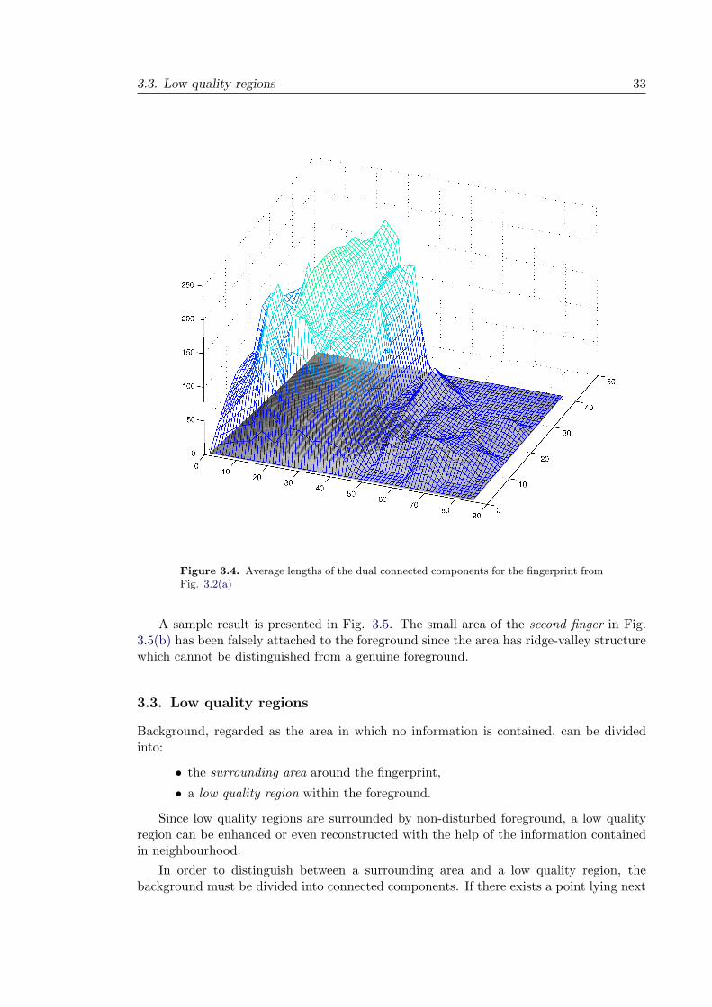
- is computed. The matrix L is divided into blocks of a given size and the average ofthe defined values is computed for each block. An exemplary matrix B for connectedcomponents from Fig. 3.2(a) is plotted as a mesh in Fig. 3.4.
3.2.3. Identifying background. With the help of the features described above, a clas-sification algorithm can be constructed for discriminating between background and fore-ground. Since the samples of features in both areas are available, we follow the supervisedlearning approach. Many different classification algorithms exist that can be applied tothis problem. One can for instance think of K−nearest neighbour classifier, neural net-works, among others to find decision boundaries. However, it is very important to use aclassification algorithm that has as low a computational complexity as possible [21]. Hencewe have decided to use a linear classifier:
y(c, m, s) = acc + amm + ass + b,
where
• c is the mean of the average dual connected component lengths in the block,
• m is the number of unvalidated minutiae in the block,
• s is the number of segments with inconsistent neighbours in the block.
And the decision for a block is:
the block
remains foreground if y(c, m, s) ≥ 0changes to background if y(c, m, s) < 0
The weights ac, am and as are determined during a supervised learning phase with thehelp of images in which the background has been marked manually.
3.3. Low quality regions 33
Figure 3.4. Average lengths of the dual connected components for the fingerprint fromFig. 3.2(a)
A sample result is presented in Fig. 3.5. The small area of the second finger in Fig.3.5(b) has been falsely attached to the foreground since the area has ridge-valley structurewhich cannot be distinguished from a genuine foreground.
3.3. Low quality regions
Background, regarded as the area in which no information is contained, can be dividedinto:
• the surrounding area around the fingerprint,
• a low quality region within the foreground.
Since low quality regions are surrounded by non-disturbed foreground, a low qualityregion can be enhanced or even reconstructed with the help of the information containedin neighbourhood.
In order to distinguish between a surrounding area and a low quality region, thebackground must be divided into connected components. If there exists a point lying next

34 3. Preprocessing using extended features
(a) (b)
Figure 3.5. The image from Fig. 3.2 binarised and segmented with commonly usedmethod [21] and its improved segmentation
(a) (b)
Figure 3.6. A fingerprint image before and after binarisation and segmentation. Thesurrounding area is marked light grey and low quality regions - dark grey
to the image border in some component, the component is declared to be the surroundingarea. Otherwise it is a low quality region. An example is shown in Fig. 3.6.
3.3.1. Connecting segments. In Section 2.4.2 border point neighbours have been in-troduced. Like a real border point each noisy point (the end of a segment at a low qualityarea border) knows its neighbours if they exist. With the help of that information, andadditionally using the neighbouring non-disrupted segments, the trace lines can be con-nected: from the outermost line towards the centre of the noisy area. The result for a lowquality region which has an equal number of segment ends at both sides (Fig. 3.7(a)) is

3.3. Low quality regions 35
(a) Low quality area with
the same number of seg-
ment ends at both sides
(b) After connection of
disrupted segments
(c) Low quality area withdifferent number of seg-ment ends at both sides
(d) After simple connect-ing. One line could notbe connected
(e) After identifying theminutia
Figure 3.7. Connecting segments
(a) (b)
Figure 3.8. Hidden minutiae in a low quality region
presented in Fig. 3.7(b). An example for a region with different numbers of segment endsat both sides is shown in Fig. 3.7(c) and the result of the line connecting is presented inFig. 3.7(d). Different numbers of line ends at both sides of a low quality area are an in-dicator for the existence of one or more minutiae in that region. A method for finding theapproximate position and direction of the minutiae is described in the following section.
Obviously, if a noisy region does not contain any minutia, the number of segment endsat one of its sides is equal to the number at the other side. However, this statement cannotbe reversed. Even if the numbers at both sides are equal, there might exist minutiae inthe low quality region as presented in Fig. 3.8. Such minutiae cannot be reconstructed byour algorithm and will be missing.
3.3.2. Minutiae in low quality regions. In this subsection we will consider a situationin which the numbers of segment ends at both sides of a low quality area differ. For whatfollows we will assume, without loss of generality, that the left side has less end pointsthan the right side.
The following two situations are possible:

36 3. Preprocessing using extended features
(a) Low quality region with odd difference in
the number of segment ends
(b) Low quality region with even difference in
the number of segment ends
(c) Correction of situation presented in (a) (d) Fitting of polynomials
Figure 3.9.
(1) There exist two neighbouring ends having same colour (Fig. 3.9(a)), i.e. bothare black or both are white.
(2) Each neighbour of an end, if one exists, lies in the dual area (Fig. 3.9(b)), so thatthe difference in the numbers of ends at both sides is even.
In the first case, any two neighbouring ends lying in the same dual area are connectedto make a bifurcation and consequently the number of ends at that side decreases by one.The result of connecting the ending for the situation presented in Fig. 3.9(a) is shownin Fig. 3.9(c). After processing of all such neighbouring endings the second condition isfulfilled. In that case the strategy is as follows.
In order to find likely connections between the disrupted segments, we use the factthat the flow of fingerprint lines is very smooth. We thus try to fit a polynomial curveto points at the ends of the disrupted segments. The connections with the best fit arechosen. Sample fits are presented in Fig. 3.9(d).
We use curves of degree 2 that can be written in the parametric form as
l(t) =(a2t
2 + a1t + a0, b2t2 + b2t + b0
)
For the approximation four points will be chosen, two for each segment. On eachsegment, one point is the end and the second is chosen at a given distance from theend. The residual sum of squares defines the cost of the connection. The lines should beconnected in a way such that the overall cost is minimised and all lines are connected.If a segment end has been connected to two other segment ends, a bifurcation is placedin the middle between the left and the right side of the low quality area since the exactposition cannot be determined. The corrected connections for the situation presented inFig. 3.7(c) are shown in Fig. 3.7(e).

Chapter 4
Classification
4.1. Introduction
This chapter discusses applications of the extended feature set for another fingerprintrecognition stage – classification.
Fingerprints have specific flow dynamics which manifest themselves in relatively dis-tinct flow patterns – these help to define classes of fingerprints. The first classification offingerprints was made by Purkinje in 1823. The most important and widespread one is SirEdward Henry’s classification, designed in 1902 as a refinement of the earlier classificationsystem by Galton. Most of the currently used classification schemes are variants of Henry’sclassification scheme [7]. The six most common classes, shown schematically in Fig. 4.2,are the following: plain arch, tented arch, left loop, right loop, whorl, and double loop.
Whereas fingerprint matching is predominantly performed with the help of local fea-tures, fingerprint classification is generally based on global features, that is, a skin ridgeflow direction and singular points. The orientation field can be used as a feature vectorfor classification [32; 33; 34]. Different procedures for a reduction of the dimension ofthe orientation field, e.g. Karhunen-Loeve transformation [35] have been proposed. Thestatistical classifiers may then be applied to the reduced vector [36; 15].
Dass and Jain [37] have proposed the utilisation of the ridge shape. However, theyactually use only level 1 features since they extract the shapes not directly from the ridgeimage but from the computed orientation field, which can lead to misclassification offingerprints containing very few indicators for their class. For the left loop presented inFig. 4.1(a)) the computed orientation field (Fig. 4.1(b)) does not contain any indicator fora left loop as the loop has been smoothed out. Consequently, the fingerprint is misclassifiedas an arch, whereas a flow line indicating a left loop can be found within the flow lineswhich are directly extracted from the ridge segments (Fig. 4.1(c)).
One of the main objectives of this thesis is to abandon the classical approach whichdistinguishes between the global and the local features. Some investigations aimed atfinding alternatives to level 1 features have already been presented in literature. Changand Fan [38] have proposed a combination of global ridge shape analysis – leading to anauxiliary classification of 10 ridge patterns – and the recognition of syntactic grammar lan-guages with a non-deterministic finite automaton. Cho et al. [39] have proposed a method
37

38 4. Classification
(a) A left loop image with asmall class indicator
(b) Orientation field, note thatthe loop was smoothed-out
(c) Class indicator from the ex-tended feature set
Figure 4.1. Small loop challenge
(a) plain arch (b) tented arch (c) whorl
(d) left loop (e) right loop (f) double loop
Figure 4.2. Characteristic lines for fingerprint classification
that classifies fingerprints according to the curvature and orientation of the fingerprintarea near the core.
Principally, our method is based on the ridge flow extracted directly from the ridgesegments. In order to deal with noisy or partial images, we will explore additional features,such as the ridge connectivity or a flow mode of ridges.
4.2. Classification
Each of Henry’s classes has a certain winding of connected lines which are class-specific.Typically, they can be found around the centre of a fingerprint (see Fig. 4.2). This suggeststhat with the help of the connected entraced lines, a characteristic line for that class maybe found. In order to determine a class it is sufficient to find one or, for robustness, a fewsuch lines.

4.3. Extended lines 39
5
6 2
43
AB1C
FGHIJ
ED
Figure 4.3. Extended line identification process
4.3. Extended lines
The obtained fingerprint structure (extracted minutiae, border points, and segments) canbe considered as two graphs, using the definitions introduced in Section 2.6.1:
GM := (VM := VM , EM := EM ∪ ED)
and
GS = (VS , ES),
where:
• VM is the set containing all minutiae and border points,
• v1, v2 ∈ EM ⇐⇒ v1 and v2 are connected via a segment or corresponddual to each other. For the situation presented in Fig. 4.3, in addition to the“natural” edges A, D, A, G, A, I, B, H, C, F, and E, J also the edge A, Bis contained in the edge set.
• VS is the set of all segments, and
• v1, v2 ∈ ES ⇐⇒ the segments v1 and v2 are neighbours. For the segments inFig. 4.3, ES = 1, 5, 1, 6, 2, 4, 2, 6, 3, 4, 3, 5.
An extended line λ is a path in the graph GM:
λ = 〈v1, e1, v2, . . . , em−1, vm〉
which connects two border points v1, vm with the additional condition that, in order torespect the natural flow, bifurcations are traversed only by following their larger angles.Hence, the only extended lines in Fig. 4.3 are: 〈C, 5, F〉, 〈D, 1, A, 3, G〉, 〈D, 1, A, eA−B, B, 4, H〉,〈D, 1, A, 2, I〉, 〈E, 6, J〉, where eA−B ∈ ED denotes the dual link between A and B. Moreover,we can equivalently use another representation of an extended line – its pointwise repres-entation:
λp = 〈p1, p2, . . . , pn〉
where p1 . . . pn are the segment points contained in the edges e1 . . . em−1.
We denote the set of all extended lines contained in a fingerprint with Λ.
4.3.1. Extended line properties. An extended line can be characterised by two descriptors:maximal change of direction and flow mode defined, as follows:

40 4. Classification
Figure 4.4. Determination of the border point side location
Maximal change of direction. The cumulative direction change of a segment defined inSection 2.5.4 can naturally be extended to extended lines.
Definition 4.1 (Cumulative change of direction). For an extended line λp = 〈p1, p2, . . . , pn〉the cumulative direction change φλ(i) up to segment point pi is the sum of directionchanges at segment points p2, . . . , pi−1:
φλ(i) :=
φλ(i − 1) + αi for 2 < i ≤ m
0 for i ∈ 1, 2
where αi ∈ (−π, π] is the change of direction at point pi−1.
Definition 4.2 (Maximal change of direction). For an extended line λ the maximaldirection change Φ(λ) is defined as follows:
Φ(λ) := maxi
(φλ(i)) − mini
(φλ(i))
4.3.1.1. Flow mode. Flow mode describes the shape of a line on a global scale. Theinformation about the side location (on the left or the right side of a fingerprint) of borderpoints required for the computation of flow modes will be introduced first. For fingerprintimages unaffected by a rotation, i.e. being aligned vertically, the value of the secondcomponent of a border point direction vector is a good indicator for its side location. If itis smaller than 0 (the direction vector points to the left), then the border point is locatedon the right side, otherwise on the left. However, that method can fail if the finger hadbeen rotated slightly before it was acquired. The border points in the marked area inFig. 4.4 can then be falsely classified as left border points. However, since every borderpoint knows its neighbour (if it has one) as described in Section 2.4.2, we can connectthe neighbouring border points together in order to build larger components. For eachcomponent its mean direction is utilised for a side assignment.

4.4. First decisions 41
Table 4.1. Flow modes
lr l1801 2
3
ll r1803
2
1
rr l360
12
3
w r360
12
3
With the help of the image sides characteristic lines can be divided into the followingclasses, illustrated in Table 4.1:
• connecting two sides of the image (lr);
• having both ends at the same image side (ll, rr);
• closed line without ends (w);
• having one end at an image side and the other end within the line (l180, r180,l360, r360).
The 180 and 360 loops are discriminated by using the branches order of the bifurc-ation (introduced in Section 2.2.2) where the loop is connected. If the loop is betweenthe second and the third bifurcation branch, it is a 180 loop. Otherwise, if the loop isconnected at the first branch, it is a 360 loop.
We introduce the set of all possible flow modes
F = lr, ll, rr, w, l180, r180, l360, r360 ,
and let Γ : Λ → F be the function which returns the flow mode for an extended line.
4.4. First decisions
If a good quality fingerprint image contains an extended line with flow mode w it is clearthat the fingerprint belongs to the whorl class. Similarly, if it has only lr extended linesand none of them has a maximal direction change larger than π
2 , it is clearly a plain arch.Hence the classification of good quality images can be achieved with the help of the treeclassifier shown in Table 4.2, where FΛ ⊂ F is the set of all flow mode among extendedlines in the set Λ,
FΛ := Γ(λ) : λ ∈ Λ
and ψΛ is the largest maximal direction change in Λ,
ψΛ = maxλ∈Λ
Φ(λ)

42 4. Classification
Table 4.2. First decision tree
Begin
double loop ψΛ ≥ 2π
whorl FΛ ∩ w, l360, r360 6= ∅
right loop FΛ ∩ rr, r180 6= ∅
left loop FΛ ∩ ll, l180 6= ∅
tented arch ψΛ > 34π
plain arch
yesno
yesno
yesno
yesno
yes
no
Figure 4.5. A sample characteristic line in a right loop fingerprint
An extended line which has fulfilled one of the five conditions resulting in the assign-ment of the fingerprint to a class other than plain arch is called a characteristic line. Asample characteristic line is presented in Fig. 4.5.
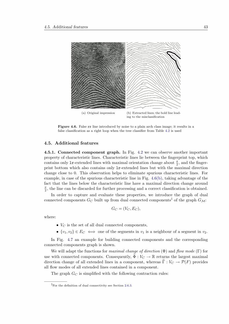
The classification described above works well for good quality fingerprint images. How-ever, in case of a noisy image a characteristic line may not be found or a spurious char-acteristic line may be extracted (Fig. 4.6), which results in a false classification. Thus,additional features are required for images of lower quality.
4.5. Additional features 43
(a) Original impression (b) Extracted lines; the bold line lead-ing to the misclassification
Figure 4.6. False rr line introduced by noise to a plain arch class image; it results in afalse classification as a right loop when the tree classifier from Table 4.2 is used
4.5. Additional features
4.5.1. Connected component graph. In Fig. 4.2 we can observe another importantproperty of characteristic lines. Characteristic lines lie between the fingerprint top, whichcontains only lr-extended lines with maximal orientation change about π
2 , and the finger-print bottom which also contains only lr-extended lines but with the maximal directionchange close to 0. This observation helps to eliminate spurious characteristic lines. Forexample, in case of the spurious characteristic line in Fig. 4.6(b), taking advantage of thefact that the lines below the characteristic line have a maximal direction change aroundπ2 , the line can be discarded for further processing and a correct classification is obtained.
In order to capture and evaluate these properties, we introduce the graph of dualconnected components GC built up from dual connected components1 of the graph GM:
GC = (VC , EC),
where:
• VC is the set of all dual connected components,
• v1, v2 ∈ EC ⇐⇒ one of the segments in v1 is a neighbour of a segment in v2.
In Fig. 4.7 an example for building connected components and the correspondingconnected components graph is shown.
We will adapt the functions for maximal change of direction (Φ) and flow mode (Γ) for
use with connected components. Consequently, Φ : VC → R returns the largest maximal
direction change of all extended lines in a component, whereas Γ : VC → P(F ) providesall flow modes of all extended lines contained in a component.
The graph GC is simplified with the following contraction rules:
1For the definition of dual connectivity see Section 2.6.3.

44 4. Classification
(a) For a part of a fingerprint.
(b) For a whole fingerprint
Figure 4.7. Dual connected components and a dual connected component graph withmarked correspondences. Each dual connected component is marked with a different
colour.
• Vertices which correspond to components not containing any extended line (e.g.containing only one line with two unvalidated endings) are removed from thegraph.
• A vertex with degree 1 is merged with its neighbour if they are compatible, thatis, they have the same flow modes and the difference in maximal direction changeis below a given threshold.
• A vertex with degree 2 is deleted and its neighbours are connected if all 3 verticesare compatible.

4.5. Additional features 45
(a) Reduced connected componentgraph
(b) Corresponding regions
Figure 4.8.
0 lr
π/2 lr
(a) For an arch
0 lr
π lr
π/2 lr
π rr
(b) For a right loop
Figure 4.9. Sample graph prototypes, dashed parts are optional
The result of this postprocessing step applied to the connected component graph fromFig. 4.7 together with the corresponding regions is presented in Fig. 4.8.
The postprocessed graph contains four vertices:
(1) component with lr flow mode and maximal direction change π2 ;
(2) component with ll flow mode;
(3) component with lr flow mode and maximal direction change near 0;
(4) component with lr and ll flow modes, adjacent to all other components. It isalso the component containing the delta point.
Consequently, prototypes for each class are constructed. The sample prototypes foran arch and a right loop are shown in Fig. 4.9. The dashed parts in Fig. 4.9(b) indicateoptional parts of the graph as there can exist either a connection between the fingerprinttop and bottom or the central part can be merged with the component containing deltabut either one must be present.
An extracted characteristic line can be validated by comparing the obtained reducedconnected component graph with the above proposed prototypes.

46 4. Classification
(a) (b)
Figure 4.10. Different delta architectures
4.5.2. Delta points. For a fingerprint the number of core points always equals the num-ber of delta points: for tented arches, right or left loops it equals 1, for whorls and doubleloops there are 2 while plain arches do not posses any.
Although delta points are not reliable features since they often lie outside of the visiblefingerprint area, our experiments have shown that the classification error rate decreaseswhen delta point information is used in the following way: if two deltas have been foundin a fingerprint it is declared to be a whorl or a double loop; if no characteristic line butone delta can be found, it is most probably a tented arch.
We will utilise only delta point information and no core point information because ofthe following reasons:
(1) Generally, if no characteristic line can be found in a noisy fingerprint which isnot a plain arch, a core point will also not be found.
(2) Delta points can easily and reliably be computed with the help of extended linesand a computation of orientation field is not required.
Deltas exist in various types. The easiest one to detect is presented in Fig. 4.10(a).Two attributes of such a delta are:
• there exists a triangle build up of three bifurcations,
• the second and the third branch of the uppermost bifurcation are adjacent to thesegments having their other ends at different image sides.
The most difficult delta architecture is presented in Fig. 4.10(b). Since there is no bifurc-ation triangle, the above listed conditions cannot be applied directly. The best solution isto utilise neighbourhood information. Another indicator for a delta point is the existenceof a star-like unvalidated bifurcation with all three angles around 60.
4.6. Final decisions
The final decision tree for classification is presented in Table 4.3 using the first classifierpresented in Table 4.2.
4.7. Results and conclusion
We have tested our method on the NIST Special Database 4 [41]. This database contains4000 fingerprint images acquired from 2000 fingers. The fingerprints are equally distributedover five classes assigned by human expert: plain arch, tented arch, left loop, right loop,

4.7. Results and conclusion 47
Table 4.3. Final decision tree
Begin
Two deltas found?
Apply the first
decision tree.
Has a characteristicline been found?
Validatethe characteristic
line.Has a deltabeen found?
Has the characteristicline has been removed?
whorldouble loop
the first classifier’sdecision tented arch plain arch
yes
no
yes
no
yes
no
yes no
Table 4.4. Comparison of error rates
4 class problem 5 class problem
Dass and Jain [37] 6.6% —Li, Yau, and Wang [40] 5% 6.5%our method 4.5% 6.3%
Table 4.5. Confusion matrix of the results on the NIST 4 Database
true predicted classclass PA TA LL RL WPA 751 35 15 12 0TA 39 747 16 9 7LL 8 6 763 11 10RL 12 10 6 733 12W 8 7 14 16 753
and whorl. The whorl class contains fingerprints from both the whorl and the double loopclass.

48 4. Classification
The performance of a fingerprint classification system is usually measured in terms oferror rate which is the ratio between the number of misclassified fingerprints and the totalnumber of samples in the test set [7]:
error rate =number of misclassified fingerprints
total number of fingerprints× 100%
Since the discrimination between a plane and a tented arch is a difficult task, we have alsocomputed, as many researches do, the error rate for the four class problem, in which planeand tended arches are identified as a single class. For the four class problem we obtained3.5% error rate, and 6.6% for the five class problem. A comparison with error rates fromthe literature is presented in Table 4.4.
A more detailed analysis of the behaviour of a classifier can be obtained by examiningthe confusion matrix which has one row for each true class and one column for eachpredicted class; each cell at row r and column c reports how many fingerprints belongingto class r are assigned to class c [7]. Table 4.5 shows the confusion matrix of the results onthe NIST 4 database for the presented approach. As even experts have problems assigninga given fingerprint to a class, some fingerprints in the database had been assigned to twoclasses. In such a case, a fingerprint is concerned as classified correctly if it has beenassigned to one of the two classes. For building the confusion matrix we report an imageas falling into the class we assigned in such a case.
In the remaining part of the section we will discuss misclassifications which occurredand the reasons.
Fingerprint classification is a difficult task due to small inter-class but large intra-class variability (Fig. 4.11). Furthermore, in a non-negligible series of images even atrained expert may have difficulty in determining a unique class in which to classify agiven fingerprint so that multiple class decisions are a possible solution.
In spite of the multiple class decisions, one can find in the NIST 4 database sets ofimages in which a visual confrontation may render it difficult to follow the expert’s decision(Fig. 4.12), for example where a delta was identified in an image which appears to showa plain arch (Fig. 4.13(b)) or where an apparent left loop appears to have been classifiedas a tented arch only because it is so acute (Fig. 4.13(c)). The distinctions are blurredand, unless one trains an algorithm on a given database, there is no apparent a prioricriterion which might enable the algorithm to duplicate the expert’s decisions. In orderto construct a database independent method, we have decided to reject such a training.
We have been confronted with considerable problems when trying to distinguish betweenthe two arch classes (Fig. 4.13(a) and 4.13(b)) as well as in case of the distinction betweenwhorls and some loops, mostly due to the presence of small pocket whorls. Moreover, thequality of images is quite an important factor. Some low quality images have their discrim-inating features removed in the enhancement stage (Fig. 4.14(b) and 4.14(c)), whereassome are difficult to classify even for a human (Fig. 4.14(a)).
Since the tests have proven the extended features’ usefulness for classification, it mightbe worth applying them for indexing. Last but not least, the refinement of the existingclasses, e.g. by dividing a class into subclasses by means of the number of characteristiclines or their curvature appears to be worth a deeper examination.

4.7. Results and conclusion 49
(a) plain arch (b) left loop (c) left loop (d) left loop (e) tended arch
Figure 4.11. An example of small inter-class and large intra-class variability.
(a) s1936 07 TA (b) f0008 10 TA LL (c) f0045 06 LL
Figure 4.12. Contentious assignments to the classes proposed by an expert. We wouldsuggest to at least assign all image as TA LL. s1936 07 was horizontally mirrored forbetter comparison.
(a) f0791 03 PA (b) f1070 07 TA (c) f0401 08 TA
Figure 4.13. Fingerprints and the expert’s decisions
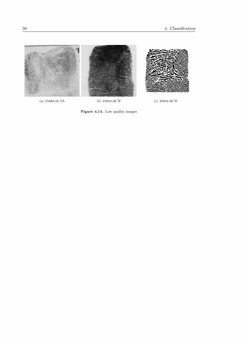
50 4. Classification
(a) f1463 02 TA (b) f0310 05 W (c) f0310 05 W
Figure 4.14. Low quality images
Chapter 5
Matching
5.1. Introduction
In general, matching two fingerprint images is a difficult task, mainly due to a greatdissimilarity of impressions of the same finger. The main factors for those large variationsare summarised below [7].
• Translation: the finger may be placed at different locations on the sensor. Al-though a well-designed sensor housing can prevent large finger displacements,even a 2 mm finger translation on the sensor results in a translation of about 40pixels in the acquired image while scanning at a resolution of 500 dpi. For anexample compare Fig. 5.1(a) and 5.1(d).
• Rotation: the finger may be placed at different angles relative to the sensor. Likein the translation case, even using a well-designed sensor cannot completely avoidrotations and as a result a rotations of about ±20 can be observed. An exampleof relatively rotated fingerprint acquisitions is shown in Fig. 5.1(a) and 5.1(c).
• Partial overlap: the above mentioned linear distortions can result in a small over-lap between the acquired images. The common part of the impressions presentedin Fig. 5.1(d) and 5.1(e) covers only about 30% of the foreground in each finger-print.
As mentioned in Section 1.3, the commonly used fingerprint sensors are touch-based,that is a finger has to be pressed onto the sensor surface. As a result additional factorsresulting in a large intra-finger variability come into play:
• Noise: finger pressure, dryness of the skin, sweat, dirt, grease and humidity inthe air may contribute to non-uniform contact with the sensor surface. As aconsequence, the acquired images are noisy.
• Skin elasticity: may contribute to distortions at all levels. On the global levelit may induce non-linear deformations of the ridge flow (Fig. 5.2). On the locallevel it may lead to change of minutiae type from an ending to a bifurcation (orthe other way round), as presented in Fig. 5.2 within the region marked in red.
51

52 5. Matching
(a) 10 1 (b) 10 2 (c) 10 3
(d) 10 4 (e) 26 1 (f) 18 6
Figure 5.1. Sample fingerprint impressions from the FVC2002 database db2 [42]
In this chapter we will first investigate the quality of minutiae extracted by the entracerusing a standard minutiae-based matching algorithm. The minutiae-based matching al-gorithm is then extended to include some of the extended features. Finally, we will presenta sketch of a matcher which fully utilises all the extracted features.

5.2. Measuring the performance of a fingerprint-based identification system 53
(a) (b)
Figure 5.2. Two impressions of the same finger affected by non-linear deformations
5.2. Measuring the performance of a fingerprint-based identification
system
In order to compare two fingerprint-based identification systems each system can be runon a given test database and error rates can be computed and compared. This sectionprovides the details of this process.
When testing the similarity of two input fingerprints, an automatic identification sys-tem provides us with a score t ∈ [0, 1]. The input fingerprints are considered as genuine,if t is greater than a given threshold t0.
In order to measure the performance of an identification system, we introduce thefollowing notation:
• F : set of fingerprints in the test database
• Fg := f1, f2 ∈ F × F : f1 and f2 come from the same finger: set of genuinepairs
• Fi := f1, f2 ∈ F × F : f1 and f2 come from different fingers: set of impostorpairs
• I : F × F → [0, 1]: a matcher
For a given threshold t0 we can compute two types of errors:
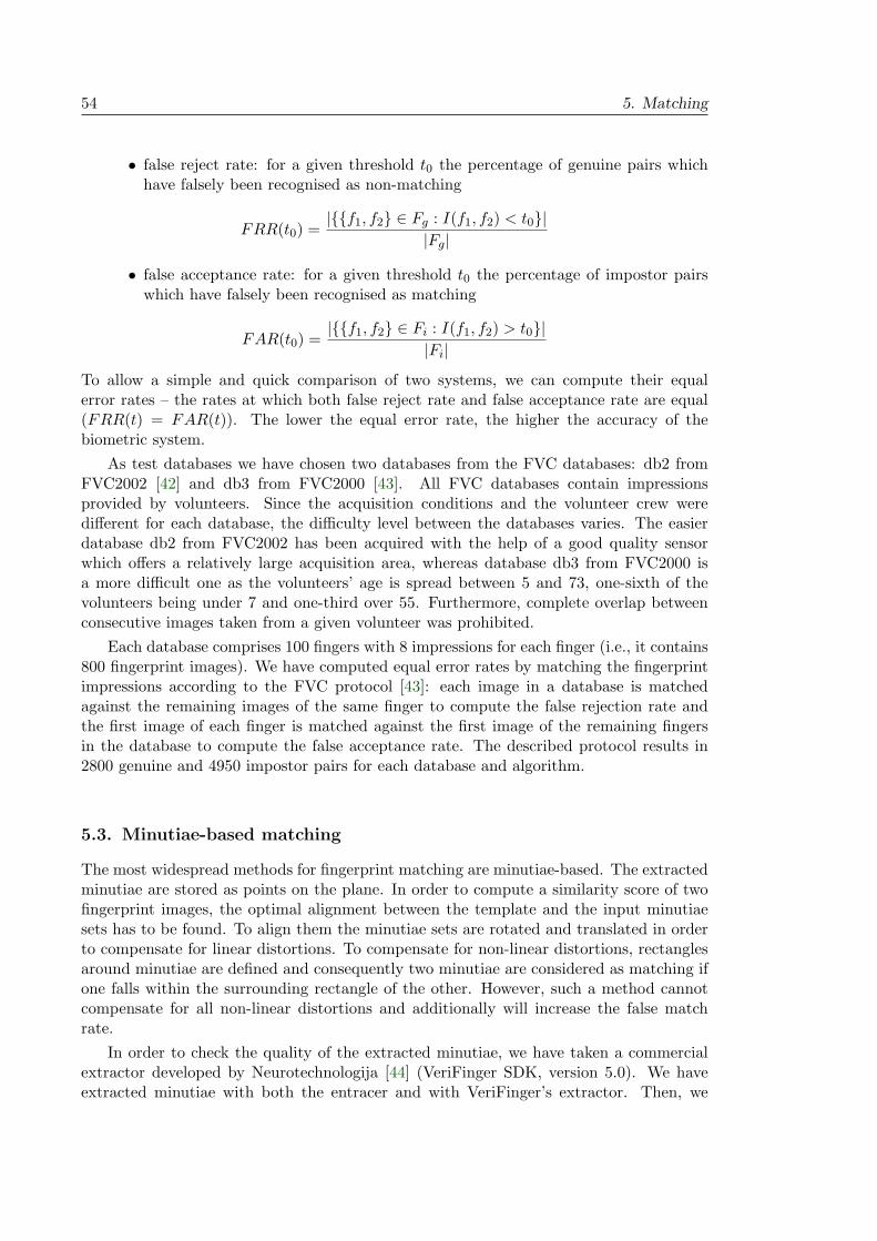
54 5. Matching
• false reject rate: for a given threshold t0 the percentage of genuine pairs whichhave falsely been recognised as non-matching
FRR(t0) =|f1, f2 ∈ Fg : I(f1, f2) < t0|
|Fg|
• false acceptance rate: for a given threshold t0 the percentage of impostor pairswhich have falsely been recognised as matching
FAR(t0) =|f1, f2 ∈ Fi : I(f1, f2) > t0|
|Fi|
To allow a simple and quick comparison of two systems, we can compute their equalerror rates – the rates at which both false reject rate and false acceptance rate are equal(FRR(t) = FAR(t)). The lower the equal error rate, the higher the accuracy of thebiometric system.
As test databases we have chosen two databases from the FVC databases: db2 fromFVC2002 [42] and db3 from FVC2000 [43]. All FVC databases contain impressionsprovided by volunteers. Since the acquisition conditions and the volunteer crew weredifferent for each database, the difficulty level between the databases varies. The easierdatabase db2 from FVC2002 has been acquired with the help of a good quality sensorwhich offers a relatively large acquisition area, whereas database db3 from FVC2000 isa more difficult one as the volunteers’ age is spread between 5 and 73, one-sixth of thevolunteers being under 7 and one-third over 55. Furthermore, complete overlap betweenconsecutive images taken from a given volunteer was prohibited.
Each database comprises 100 fingers with 8 impressions for each finger (i.e., it contains800 fingerprint images). We have computed equal error rates by matching the fingerprintimpressions according to the FVC protocol [43]: each image in a database is matchedagainst the remaining images of the same finger to compute the false rejection rate andthe first image of each finger is matched against the first image of the remaining fingersin the database to compute the false acceptance rate. The described protocol results in2800 genuine and 4950 impostor pairs for each database and algorithm.
5.3. Minutiae-based matching
The most widespread methods for fingerprint matching are minutiae-based. The extractedminutiae are stored as points on the plane. In order to compute a similarity score of twofingerprint images, the optimal alignment between the template and the input minutiaesets has to be found. To align them the minutiae sets are rotated and translated in orderto compensate for linear distortions. To compensate for non-linear distortions, rectanglesaround minutiae are defined and consequently two minutiae are considered as matching ifone falls within the surrounding rectangle of the other. However, such a method cannotcompensate for all non-linear distortions and additionally will increase the false matchrate.
In order to check the quality of the extracted minutiae, we have taken a commercialextractor developed by Neurotechnologija [44] (VeriFinger SDK, version 5.0). We haveextracted minutiae with both the entracer and with VeriFinger’s extractor. Then, we

5.4. Consistency-based matching 55
Table 5.1. Equal error rates for minutiae matching
Neurotechnologija Entracer
FVC2002 db2 1.056% 0.953%
FVC2000 db3 7.692% 7.253%
have used the matcher from the VeriFinger SDK to match the extracted minutiae sets1.The results are presented in Table 5.1.
These tests show that the error rates are reduced even when no additional extractedfeatures are used. In the next step, we extended the matching algorithm so that it exploitsthe advantages of some of the extended features.
5.4. Consistency-based matching
First, the extracted minutiae are matched with the help of a minutiae-based matchingmethod. Next, the following consistency test is applied.
Let GM = (U, EM , ED) and HM = (V, FM , FD) be the extracted fingerprint graphs(see Section 2.6.1) for the fingerprints to be matched.
Let M be the set of all matched minutiae pairs
M := (ui, vi)ni=1 ⊂ U × V
M is a relation between the elements of the set U and the set V . Let Um ⊆ U andVm ⊆ V be its domain and its range, respectively, that is:
[∀u∈Um∃v∈Vm
(u, v) ∈ M ] ∧ [∀v∈Vm∃u∈Um
(u, v) ∈ M ]
For the consistency test we take two minutiae u1, u2 ∈ Um that lie in the same extendeddual connected component of the graph GM . For the corresponding matched minutiae inthe second fingerprint
v1, v2 ∈ Vm : (u1, v1) ∈ M ∧ (u2, v2) ∈ M
we check the following conditions in a top-down manner, that is, if any of earlier conditionsis not fulfilled, the following conditions will not be checked:
• v1 and v2 lie in the same extended dual connected component of the graph HM ,
• the difference of line distances is below a given threshold:
|dedl (u1, u2) − ded
l (v1, v2)| < td,
• the difference in the cumulative direction change on the shortest path betweenthe vertices is below a certain threshold
|φed(u1, u2) − φed(v1, v2)| < tφ.
Consequently, the scores for pairs (u1, v1) and (u2, v2) are updated according to theresult of the consistency test.
This method does not exhaust the full power of the extended features as it onlydecreases scores for falsely matched minutiae, whereas the main reason for using extendedfeatures is to decrease the false rejection rate in case the level 2 features (usually minutiae)do not provide enough information to declare a pair as genuine [6]. However, even with
1For the tests we have not used any additional extracted information but only minutia position and direction.

56 5. Matching
Table 5.2. Equal error rates for consistency based matching
Neurotechnologija Entracer
FVC2002 db2 1.056% 0.784%
FVC2000 db3 7.692% 6.727%
the simple extension described above we were able to decrease the equal error rates, asshown in Table 5.2.
5.5. Extended features-based matching
In this section a new approach to fingerprint matching is described, taking into accountthe information about minutiae, ridges and particularly the connectivity information con-tained in the extracted fingerprint structure. Consequently, global and local features areconnected so that the automatic matching resembles more closely the way human expertsproceed.
Although the consistency-based method (described in the last section) already usesextended features, it still utilises a minutiae-based matching algorithm. The methoddescribed in this section adopts a thoroughly different approach to matching. Insteadof globally aligning minutiae sets, each pair of minutiae is compared with the help ofthe information contained in the connected component to which the minutiae belong.This results in a minutiae similarity score. After all minutiae in a fingerprint have beencompared, a global similarity score for the two fingerprints is determined.
In the following subsections the concepts of segment similarity, minutiae score andfinally fingerprint similarity score are introduced. GM = (VM , EM , ED) denotes theminutiae-vertex graph introduced in Section 2.6.1.
5.5.1. Segment similarity. In order to define segment similarity the following segmentfeatures are compared:
• Length: their relative difference is computed and if it is below a given threshold,the lengths are considered to be similar:
|l1 − l2|
max(l1, l2)< c;
where c is an empirically chosen constant.
• Maximal curvature or curvature course: provides a good measure for fingerprintswhich have only linearly been disturbed. In case of non-linear distortions thelocal curvature can change diametrically as for example in the top left regionof the fingerprint presented in Fig. 5.2. Hence the following features are moresuitable.
• Maximal change of direction: see Section 4.3.1. Their difference is computedrelatively as in the case of the length.
• Sign of the global direction change: provides the information whether a line isleft- or right-twisted.
Since the set of features and the comparison techniques used for similarity tests havebeen specified only partially so far, for further investigation the following binary similarityfunction is defined:

5.5. Extended features-based matching 57
σ( , 0)v vδ( , 3)
vδ( , 2)vσ( , 1)
vδ( , 1)vβ( , 0)=0
t(v) = bifurcation
v
v
v
δ( , 0)
σ( , 2)
v
v
v
β( , 1)=1
β( , 2)=1
B(v) =0, 1, 2, 3
β( , 3)=3
vσ( , 3)
Figure 5.3. Sample values of functions for minutiae similarity score computation
Definition 5.1 (Similar segments - s(s1, s2)). The function s : EM ×EM → 0, 1 returns1 if the segments s1, s2 are similar, i.e. pass the similarity tests, and 0 otherwise.
5.5.2. Minutiae similarity score. In this subsection we proceed to the comparison oftwo minutiae. This approach explores the connectivity information. The score is computedrecursively that is the minutiae and their adjacent segments are compared; if they can beconsidered as similar, the minutiae at the other ends of the segments are compared. Asa result, both a similarity score and a connected component which contains minutiaeand segments included into the comparison are obtained. In order to write down thiscomparison concept, some additional functions have to be defined.
Definition 5.2 (Type of a vertex – t(v)). t : VM → ending, border point, bifurcation.
Definition 5.3 (Valid branches). The function B : VM → P(0, 1, 2, 3) returns the setof all the valid branches of a vertex. The return values are presented below. The branchwith number 0 is a dual connection.
v B(v)non-validated ending,
border point 1validated ending 0, 1
non-validated bifurcation 1, 2, 3validated bifurcation 0, 1, 2, 3
Definition 5.4 (Adjacent minutia – δ(v, b)). The function δ : VM × 0, 1, 2, 3 → VM
returns the minutia at the opposite end of the segment adjacent to vertex v at branch b.The valid values of b are contained in the set B(v). In case minutia v is validated, δ(v, 0)is the corresponding dual minutia.
Definition 5.5 (Adjacent segment – σ(v, b)). The function σ : VM×0, 1, 2, 3 → EM∪ED
returns the segment adjacent to vertex v at branch b. The valid values of b are containedin the set B(v). Like for δ, if minutia v is validated, σ(v, 0) is an edge from the set ED.
Definition 5.6 (Branch at the adjacent minutia – β(v, b)). The function β : VM ×0, 1, 2, 3 → 0, 1, 2, 3 returns the index of the branch at which segment σ(v, b) is con-nected to minutia δ(v, b).
Exemplary values for the functions introduced above are presented in Fig. 5.3. In thenext part of this section we will proceed with the comparison of two minutiae.
Let G = (U, EM , ED) and H = (V, FM , FD) be the extracted fingerprint graphs (seeSection 2.6.1) for the fingerprints to be matched. For two minutiae u ∈ U and v ∈ V the

58 5. Matching
Table 5.3. Computation rules for ms
in(u, bu, v, bv, s). The introduced vertex v′ is anew bifurcation created while connecting the neighbouring segment ending to the linebeing followed. In order to find whether there exists an appropriate ending, the virtualminutiae are utilised.
G H return valueexampleon figure
1 t(u) = ending t(v) = ending s + 1 5.4(a)
2 t(u) = border point t(v) = border point
s + 1 if same image side,
0 otherwise5.4(b)
3 t(u) = border point
t(v) ∈ ending,
bifucarion s + 0.75 5.4(c)
4 t(u) = bifurcation
t(v) = bifurcation,bv = bu s + 1 +
∑b 6=bv
mout(u, b, v, b, 0) 5.4(d)
5
t(u) = bifurcation,
bu ∈ 1, 2 t(v) = ending s + 34
+ msin(u, bu, v′, b′v) 5.4(e)
6
t(u) = bifurcation,
bu ∈ 1, 2
t(v) = bifurcation
bv ∈ 1, 2 ∧ bv 6= bu s + 12
+ msin(u, bu, v′, b′v) 5.4(f)
7t(u) = bifurcation,
bu = 0
t(v) = bifurcation,
bv ∈ 1, 2 s + 14
+ maxb∈1,2
(mout(u, b, v, 0, 0)) 5.4(g)
8t(u) = bifurcation,
bu = 0 t(v) = ending s + 14
+ maxb∈1,2
(mout(u, b, v′, 0, 0)) 5.4(h)
similarity score between them is denoted with m(u, v). The function m : U × V → R isdefined for two vertices of the same type (t(u) = t(v)) as follows:
m(u, v) =∑
b∈B(u)∩B(v)
mout(u, b, v, b, 0),
where the recursive function mout : U × 0, 1, 2, 3 × V × 0, 1, 2, 3 × R → R is definedbelow.
Definition 5.7 (Outgoing match – mout(u, bu, v, bv, s)). The function mout : U×0, 1, 2, 3×V ×0, 1, 2, 3×R → R compares the segments adjacent to the input minutiae. The func-tion takes the following arguments:
• u, v - minutiae from the sets U and V respectively;
• bu, bv - the indices of branches at which the segments to be compared are connected;
• s - the similarity score computed from the minutiae compared so far.
and is defined by the following equation:
mout(v, bv, u, bu, s) =
=
msin(δ(v, bv), β(v, bv), δ(u, bu), β(u, bu), s) if s(σ(v, bv), σ(u, bu)) = 1;
mdin(δ(v, bv), β(v, bv), σ(u, bu), s) otherwise, if l(σ(v, bv) < l(σ(u, bu);
mdin(σ(v, bv), δ(u, bu), β(u, bu), s) otherwise, if l(σ(v, bv) > l(σ(u, bu).
The functions msin, md
in and mdin are defined below.
Definition 5.8 (Incoming match for similar segments – msin(u, bu, v, bv, s)). The function
msin : U×0, 1, 2, 3×V ×0, 1, 2, 3×R → R returns the score for two minutiae reached by
segments which have been regarded as similar. The function has the following arguments:

5.5. Extended features-based matching 59
(a)
(b)
or
(c)
(d)
(e)
(f)
(g)
(h)
Figure 5.4. The situations which may arise in the case of similar segments. The dashedlines are processed in the direction of the arrow which points at the vertex u or v,
respectively.

60 5. Matching
Table 5.4. Computation rules for md
in(u, bu, e, s)
additional condition return valueexampleon figure
1 t(u) = border point s 5.5(a)
2 t(u) = bifurcation
an appropriate endingon the neighbour of e exists s + 1
2+ ms
in(u, bu, v′, b′v) 5.5(b)3 t(u) = bifurcation no appropriate ending s 5.5(c)
4 t(u) = ending
an appropriate endingon the neighbour of e exists s + ms
in(u′, b′u, v′, b′v) 5.5(d)4 t(u) = ending no appropriate ending s 5.5(e)
• u, v - vertices in fingerprint graphs G and H, respectively;
• bu, bv - the branches at which the vertices u and v, respectively, have been reached;
• s - the similarity score computed from the minutiae compared so far.
The computation rules are presented in Table 5.3.
The inclusion of the “score computed so far” to the parameter list allows us to introducea stopping condition for aborting the computation of the similarity score when a clearindicator for non-matching arises. An example of such a condition is the second rule inTable 5.3.
Definition 5.9 (Incoming match for different segments – mdin(u, bu, e, s)). The function
mdin : U × 0, 1, 2, 3 × (FM ∪ FD) × R → R returns the similarity score in the case of
non-similar segments. The function takes the following arguments:
• u - a vertex in the fingerprint graph G;
• bu - the branch at which vertex u has been reached;
• e - the segment in graph H compared with the segment adjacent to vertex u atbranch bu;
• s - the similarity score computed from the minutiae compared so far.
The computation rules are presented in Table 5.4.
Since function mdin : (EM ∪ ED) × V × 0, 1, 2, 3 × R → R is symmetric to function
mdin : U × 0, 1, 2, 3 × (FM ∪ FD) × R → R, its definition is not presented.
While the similarity score for minutiae u and v is being computed, minutiae belongingto the connected components which contain u and v, respectively, are matched onto eachother. As a result we get a match set defined as follows.
Definition 5.10 (Match set for a vertex pair (u, v) – M(u, v) ⊂ U ×V ). The set M(u, v)contains all minutia pairs matched during the approach described above when starting atthe vertices u ∈ U and v ∈ V :
M(u, v) = (ui, vi) ∈ U × V
Obviously (u, v) ∈ M(u, v) and M(u, v) defines a relation on U ×V . Let us denote itsdomain and its range with UM(u,v) and VM(u,v)
2, respectively. A crucial property of matchsets is their consistency, which means that every minutia has been matched with at mostone minutia:
2In the following, we omit the dependence on (u, v) when it does not lead to confusion.

5.5. Extended features-based matching 61
(a)
(b)
(c)
(d)
(e)
Figure 5.5. The situations which may arise in case of non-similar segments. The dashedlines are processed in the direction of the arrow which points at the vertex u or v,
respectively.
Definition 5.11 (Match set consistency). A match set M ⊂ U × V is consistent if M
defines a bijective function M : UM → VM , that is, the following two conditions arefulfilled:
(u1, v1) ∈ M ∧ (u2, v1) ∈ M ⇒ u1 = u2
(u1, v1) ∈ M ∧ (u1, v2) ∈ M ⇒ v1 = v2
5.5.3. Fingerprint similarity score. For two minutiae u ∈ U and v ∈ V , the com-parison algorithm described in the previous subsection provides us with a match scorem(u, v) and a consistent match set M(u, v). Samples of computed score values for twoimpostor fingerprints are presented in Table 5.5 and for two genuine ones in Table 5.6.From these partial results a global similarity score has to be computed. Three approachesare proposed in the following subsections.
Bipartite graph. Let
m := (u, v) ∈ U × V : m(u, v) > 0

62 5. Matching
Table 5.5. A sample subset of minutiae scores for an impostor fingerprint pair
minutiae in the minutiae in the second fingerprintfirst fingerprint 1 2 3 4 5 6 7 8 9 10
1 0 0.09 0 0 0 0 0 0 0.31 02 0 0 0 0 0 0 0.49 0 0 03 0.13 0 0 0 0 0 0 0 0 04 0 0 0 0 0.21 0 0 0 0 0.195 0 0 0 0 0 0 0 0 0 06 0.83 0 0 0 0 0 0 0 0 07 0.16 0 0 0 0 0 0 0 0 0
Table 5.6. A sample subset of minutiae scores for a genuine fingerprint pair. The scoresfor the corresponding minutiae are marked bold
minutiae in the minutiae in the second fingerprintfirst fingerprint 1 2 3 4 5 6
1 0 0 0.66 0 0 02 0 0.15 0 0 0 03 0 0 0.28 0 0 04 0.50 0 0 0 0.12 05 0 0.12 0 0 0.66 06 0 0 0 0.21 0 07 0 0 0 0 0 0.838 0 0.73 0 0 0 0.23
be the set of all non-zero matching minutiae pairs. The goal is to find a consistent subsetm of m which maximises the global score
∑
(u,v)∈bm
m(u, v).
In order to find such a subset, let us consider a bipartite graph
GB := ((U, V ), EB)
in which the edge set EB contains an edge (u, v) with weight w iff there exist a non-zeromatch between minutiae u ∈ U and v ∈ V with the score w. Such a graph for the matchmatrix from Table 5.6 is presented in Fig. 5.6. The problem of finding the maximalconsistent matching is then equivalent to the problem of finding the maximal matchingin the bipartite graph GB. This is the well-known weighted marriage problem [45] whichcan be solved in polynomial time.
Unfortunately, this method computes a high similarity score also for impostor pairsas it does not take the dependencies between the matched pairs into account. Methodstaking this problem into account are presented in the next subsections.
Displacement vectors. In order to decrease the similarity score for impostor pairs in thelast method, some connections between minutiae pairs have to be introduced.
Let us consider a displacement vector for a matched minutia pair (u, v) ∈ U×V , that isa vector originating at the position of minutia u and pointing to the position of minutia v.Examples of displacement vectors for minutia pairs with a non-zero score of the fingerprints

5.5. Extended features-based matching 63
1
3
0.66
2
2
0.15
3
0.33
4 10.50
5
0.12
5
0.12
0.66
6 40.21
7
60.83
8
0.73
0.23
Figure 5.6. Bipartite graph for the scores presented in Table 5.6
0 50 100 150 200 250 300
010
020
030
040
050
0
(a) 10 1 10 2
0 50 100 150 200 250 300
010
020
030
040
050
0
(b) 10 1 10 3
0 50 100 150 200 250 300
010
020
030
040
050
0
(c) 10 1 10 4
0 50 100 150 200 250 300
010
020
030
040
050
0
(d) 18 6 26 1
Figure 5.7. Displacement vectors for fingerprints from Fig. 5.1. Three genuine pairsand one impostor pair.
given in Fig. 5.1 are presented in Fig. 5.7. We can observe that most displacement vectorsfor a genuine fingerprint pair correlate with some linear transformation, whereas such alinear transformation cannot be found for an impostor pair. Consequently, one can finda linear transformation Tϕ,o,t containing a rotation by an angle ϕ around a point o andtranslation by t approximating the displacement of a majority of the minutiae pairs in amatch. The transformation Tϕ,o,t for a point p in the plane is defined by
Tϕ,o,t(p) := (p − o) ·
(cos ϕ − sinϕ
sinϕ cos ϕ
)+ o + t
Thus, in order to compute a global score the weighted marriage problem describedabove can be applied but with the additional constraint that the displacement of matchedpairs should conform to a linear transformation. Obviously, due to the non-linear deform-ations and the inexact determination of a minutia position, the conformance to a linear

64 5. Matching
transformation should not be strict. The degree of accepted non-linear deformations iscorrelated with the degree of the conformance relaxation. Obviously, the higher the re-laxation, the larger is the false match rate. The following subsection introduces a methodfor dealing with this problem.
Clique approach. In the matching approaches described above two minutiae pairings (u1, v1)and (u2, v2) are accepted if the following condition is fulfilled:
u1 = u2 ⇐⇒ v1 = v2
However, even if the above condition is fulfilled it may happen that there exist two pairsin the corresponding match sets : (u′
1, v′1) ∈ M(u1, v1) and (u′
2, v′2) ∈ M(u2, v2), so that:
(u′
1 = u′2 ∧ v′1 6= v′2
)∨
(u′
1 6= u′2 ∧ v′1 = v′2
).
This leads us to the following definition.
Definition 5.12 (Compatible matching sets). Two consistent match sets M1, M2 arecompatible if M1 ∪ M2 is a consistent match set for a match between UM1
∪ UM2and
VM1∪ VM2
, i.e. it complies with the following requirements:
(u1, v1) ∈ M1 ∧ (u2, v1) ∈ M2 ⇒ u1 = u2,
(u1, v1) ∈ M1 ∧ (u1, v2) ∈ M2 ⇒ v1 = v2.
LetM := M(u, v) : u ∈ U ∧ v ∈ V ∧ m(u, v) > 0
be the set of all minutiae match sets with a non-zero match score. The goal is to find a
subset M of M so that all match sets in M are compatible to each other and the globalscore ∑
u,v:M(u,v)∈cM
m(u, v)
is maximal.
In order to find such a subset M, let us consider the graph
GM := (VM, EM)
in which the vertex set VM ⊂ U×V contains all the matched minutiae pairs with a positivescore and there exists an edge ((u1, v1), (u2, v2)) ∈ E iff match set M(u1, v1) is compatible
with match set M(u2, v2). The problem of finding a subset M which maximises the scoreis then equivalent to the weighted clique (complete subgraph) problem. Unfortunatelythe problem of finding a maximal clique is NP-hard [46]. However, as the graph GM isusually small and sparse the computation time required to find a desired clique is notunreasonable. Empirical tests have shown that a long computation time is needed onlyfor few fingerprints.
5.5.4. Conclusion. In this section a novel approach to fingerprint matching has beendescribed. The method has however not been completely developed. There are a fewsteps in which the approach calls for improvements. It may be worthwhile considering acontinuous function which returns a segment similarity score instead of a binary function.Furthermore, it would also be reasonable to additionally introduce segment neighbourhoodinformation so that the segments not adjacent to any bifurcation or ending might beincluded in the matching process.

Chapter 6
Development process
and software
environment
6.1. Design and development
The design and development process which has been used for constructing the methodsdescribed above is briefly presented in Table 6.1 and explained in greater detail in whatfollows. After the implementation of a new approach, the research is carried on to themain step - the interactive testing on chosen fingerprint images. These visually controlledtests give a valuable feedback for perfecting the methods and their implementation. Aftercompleting the interactive step, the approach is non-interactively tested over a large fin-gerprint image database. The outliers, that is the impressions for which the method failsor the achieved error rates are high, can then be identified and processed in the interactivestage in order to find improvements.
Using an interactive approach simplifies more or less technical procedures such choos-ing between methods or parameter tuning. Methods can be applied on a small sector of
Table 6.1. Stages in the development process
concept
implementation
interactive testson selected images
test overlarge database
result
65

66 6. Development process and software environment
the image, which provides us with a more detailed view. Furthermore, in order to findan appropriate method from a large set of candidates, as for example in image processingsteps, different methods can easily be applied at the same time in order to judge theirinfluences. After the right method has been found, its parameters can easily be tuned.Consequently, the interactive step supplies us with an answer to the question: How do theparameters or methods influence the outcome? However, for a fruitful research it is evenmore important to know the answer to the question: Why do the parameters or methodsinfluence the outcome in that manner? The support gained for getting the answer tothe latter question is the most valuable, though in a sense indirect, contribution of theinteractive step. The interactive investigation provides us with a feeling for the complic-ated structure of a fingerprint: one can precisely observe where problems arise and one’sapproach is improved gradually through assessing one’s results.
The interactive development can be well illustrated in the example described below.During the development of the entracer, a single line was traced at the beginning. Thestarting point for the tracer was manually chosen by pointing with the mouse. The linefollowing process was done step by step so that the influence of the different parameterssuch as feeler length or number of angles could be monitored. The behaviour of the tracerin difficult areas such as ones disturbed by noise or close to singular points, with highridge curvature, could be tracked. In the next step, the tracer was applied to the wholeimage, and again the results could be utilised for further improvement.
6.2. Software environment for research and development
The approach described above for conducting the research has contributed to the creationof an environment for fingerprint investigation. It is a software platform which includesimplementations of common methods from image analysis and fingerprint processing, thenew methods presented in this thesis as well as interactive tools. The environment iscomposed of three parts:
• faul: the main part with a graphical interface,
• kfinger: a package for statistical evaluation,
• fate: a library with a functional programming approach to selected problems.
For the development of the whole platform only free software has been used. Althoughthe environment has been developed under the Linux operating system, the libraries andcompilers used are platform independent and thus the environment can easily be migratedto other operating systems.
The following sections provide for a brief description of the platform.
6.2.1. faul. This part, written in C++ and compiled under the GNU GCC compiler [47],is built up of three modules:
• fingerprint processing methods: the part containing both common and new meth-ods for fingerprint processing,
• graphical user interface: the front-end implemented with the wxWidgets toolkit [48],allowing interaction,
• command line interface: allows scripted execution of the methods which is usefule.g. for tests over large databases.

6.2. Software environment for research and development 67
Figure 6.1. Graphical user interface of faul
Fingerprint processing methods. The software is built modular and implemented in anobject-oriented style. The core classes are listed below:
• Finger - class holding the fingerprint image, containing I/O-procedures for load-ing and saving, functions for image processing as well as implementations ofcommon methods;
• Minutia - class holding a single minutia;
• FingerMinutiae - container holding all the minutiae in a fingerprint;
• FingerTracerBase - contains the entracer methods;
• TracerMinutia - class derived from the Minutia class. The base class has beenextended with members and methods required for the tracing process such aslinks to adjacent segments;
• FingerTracerMinutiae - class derived from the FingerMinutiae class. Likefor the last class, the base class has been extended with members and methodsrequired for the tracing process;
• Segment - class holding a single segment, containing methods for computing de-scriptive characteristics of a segment such as its orientation change or curvaturecourse;
• FingerTracerGraph - class holding all the segments, and the connectivity in-formation between segments and minutiae which define the fingerprint graph.

68 6. Development process and software environment
Graphical user interface. A screenshot of the software in use is presented in Fig. 6.1; themain features of the graphical front-end are listed below:
• interactive– parameter adjustment,– method selection,– pointwise or regional application,– keeping track of how an algorithm proceeds;
• log-window which displays the textual output of the methods;
• graphical display results when applying a method;
• selection of features to be displayed.
6.2.2. kfinger and fate. Although the main part of the platform has been implementedin the C++ language, two parts have been separately implemented in other programminglanguages more suitable for particular tasks.
Accordingly, the R programming language and software environment [49] has beenused for the statistical evaluation.
Furthermore, some of the methods has been developed with the help of a functionalprogramming language. Since functional programming provides one with a higher levelof abstraction than imperative programming, the former is more suitable for handlingcomplicated abstract mathematical structures. For the present platform, the functionalapproach has been used for graph processing and recursive matching. OCaml (objectivecaml) [50] has been chosen for the implementation as it unifies functional, imperative, andobject-oriented programming under an ML-like type system [51]. The OCaml’s tool setincludes an interactive top-level interpreter and an optimising native code compiler whichprovides a fast running executable for integration with the faul platform.

Chapter 7
Conclusion
Traditionally, minutiae have been used as primary features for fingerprint comparisonand global features only for classification. The primary goal of this thesis has been toinvestigate the use of alternative features that can be extracted from fingerprint images,which includes a proposal for introducing a hierarchically linked extended feature set anda new entropy-sensitive extraction approach.
The universal class of features defined in this thesis can be applied in various stagesof fingerprint processing since the features combine the global and local scales which areordinarily used separately. Consequently, this approach makes the automatic fingerprintrecognition procedure more similar to the way human experts work. The tests performedfor classification and matching have shown a performance increase as the result. Simil-arly, new approaches for other stages in fingerprint processing have been proposed. Theaddressed stages are presented in Fig. 7.1.
Figure 7.1. Potential applications of the entracer. The green marked ones have beenalready successfully performed. For the double coloured applications a realisation sketchhas been presented in this thesis. The blue ones have not been investigated yet.
69

70 7. Conclusion
The entracer introduced in Chapter 2 is a novel approach to fingerprint feature extrac-tion. The extraction proceeds in two stages. First, information contained in a fingerprintis extracted and stored in the fingerprint structure as a basis for the feature extraction.The features required for a particular task are then computed from the structure.
Features such as lengths of connected components in the fingerprint graph or numberof unvalidated minutiae have been employed for the segmentation improvement describedin Chapter 3. Furthermore, connectivity information has been used for reconstructingfingerprint lines in low quality areas.
In Chapter 4 the extended lines extracted from the fingerprint structure have suc-cessfully been applied to fingerprint classification and a possible application to fingerprintindexing has been proposed.
Minutiae - the conventional features used for matching - are also contained in thisstructure. Their quality has been tested in Chapter 5. Additionally, a sketch of a matchingapproach which fully utilises the extended features has been presented.
The thesis provides a good basis for applications of the new features for other tasks infingerprint processing, as well. The extracted features are robust, which is crucial for se-curing a template. Finally, since the features are extracted from the underlying fingerprintstructure exclusively, storing of the structure instead of the whole fingerprint requires lessmemory, and can save resources. Furthermore, it would be desirable to investigate theproblem of reconstruction of a fingerprint image from its fingerprint structure.
It would be also worth considering an application of the methods described in thisthesis for recognition of other structures build up of parallel running ridges, such as tree-rings.

Index
B(v) - valid branches, 57
ED, 26
EM , 26
GC - dual connected component graph, 43
GM , 26
M(u, v) ⊂ U × V - match set for a vertices pair(u, v), 60
VM , 26
β(v, b) - branch at the adjacent minutia, 57
mdin
(u, bu, e, s) - Incoming match for different
segments, 60
mdin
(u, bu, e, s) – Incoming match for differentsegments, 60
m - bipartite graph, 61
σ(v, b) - adjacent segment, 57
m(u, v) - similarity score, 58
msin
(u, bu, v, bv , s) – incoming match for similarsegments, 58
mout(u, bu, v, bv , s) – outgoing match, 58
s(s1, s2) - similar segments, 57
t(v) - type of a vertex, 57
Adjacent minutia - δ(v, b), 57
Adjacent segment - σ(v, b), 57
Aura, 15
Bifurcations ladder, 20
Biometrics, 3
Branch at the adjacent minutia - β(v, b), 57
Branches of a bifurcation, 17
Bridging, 23
Centring on a line, 18
Compatible matching sets, 64
Connectivity systems, 27
Consistency of a match set, 61
Displacement vectors, 62
Dual connected component graph - GC , 43
Feature levels, 4
Gabor filters, 14
Incoming match for different segments –md
in(u, bu, e, s), 60
Incoming match for different segments –
mdin
(u, bu, e, s), 60Incoming match for similar segments –
msin
(u, bu, v, bv , s), 58
Match set for a vertices pair (u, v) -
M(u, v) ⊂ U × V , 60
Orientation field, 13
Outgoing match – mout(u, bu, v, bv , s), 58
Short segments, 20
Similar segments - s(s1, s2), 57Similarity score - m(u, v), 58
Type of a vertex - t(v), 57
Valid branches – B(v), 57
Validation, 20
71


Bibliography
[1] S. Pankanti, S. Prabhakar, and A. K. Jain, “On the individuality of fingerprints,”IEEE Transactions on Pattern Analysis and Machine Intelligence, vol. 24, no. 8, pp.1010–1025, Aug. 2002.
[2] A. Jain and S. Pankanti, “Biometric systems: Anatomy of performance,” IEICEtransactions on information and systems, vol. 84, no. 7, pp. 788–799, 2001.
[3] A. K. Jain, K. Nandakumar, and A. Nagar, “Biometric template security,” EURASIPJournal on Advances in Signal Processing, vol. 2008, 2008, article ID 579416, 17 pages.
[4] J. Zhou and J. Gu, “Modeling orientation fields of fingerprints with rational complexfunctions,” Pattern Recognition, vol. 37, pp. 389–391, 2004.
[5] A. K. Jain, S. Prabhakar, and S. Pankanti, “On the similarity of identical twinsfingerprints,” Pattern Recognition, vol. 35, no. 11, pp. 2653–2663, 2002.
[6] A. K. Jain, Y. Chen, and D. Meltem, “Pores and ridges: high-resolution fingerprintmatching using level 3 features,” IEEE Transactions on Pattern Analysis and MachineIntelligence, vol. 29, no. 1, pp. 15–27, 2007.
[7] D. Maltoni, D. Maio, A. K. Jain, and S. Prabhakar, Handbook of Fingerprint Recog-nition. New York: Springer, 2003.
[8] A. K. Jain and S. Pankanti, Automated Fingerprint Identification and Imaging Sys-tems, ser. Crc Series in Forensic and Police Science. CRC Press, 2001, ch. 8, pp.275–326.
[9] A. Lumini, D. Maio, and D. Maltoni, “Continuous vs. exclusive classification forfingerprint retrieval,” Pattern Recognition Letters, vol. 18, no. 10, pp. 1027–1034,1997.
[10] X. Xiongwu and L. O’Gorman, “Innovations in fingerprint capture devices,” PatternRecognition, vol. 36, no. 2, pp. 361–369, 2003.
[11] N. Yager and A. Amin, “Fingerprint verification based on minutiae features: a re-view,” Pattern Analysis Application, vol. 7, pp. 94–113, 2004.
[12] N. Yager, “Hierarchical fingerprint verification,” Ph.D. dissertation, School of Com-puter Science and Engineering, University of New South Wales, 2006.
73

74 Bibliography
[13] CDEFFS: the ANSI/NIST Committee to Define an Extended Fingerprint FeatureSet. [Online]. Available: http://fingerprint.nist.gov/standard/cdeffs
[14] A. Hicklin, CDEFFS – Extended Feature Sets, Latent Testing Workshop,National Institute of Standards and Technology, 2006. [Online]. Available:http://www.itl.nist.gov/iad/894.03/latent/presentations.htm
[15] L. Hong, Y. Wan, and A. K. Jain, “Fingerprint image enhancement: Algorithmand performance evaluation,” IEEE Transactions on Pattern Analysis and MachineIntelligence, vol. 20, no. 8, pp. 777–789, Aug. 1998.
[16] D. Maio and D. Maltion, “Direct gray-scale minutiae detection in fingerprints,” IEEETransactions on Pattern Analysis and Machine Intelligence, vol. 19, no. 1, pp. 27–40,1997.
[17] D. Maio and D. Maltoni, “Minutiae extraction and filtering from gray-scale im-ages,” in Intelligent Biometric Techniques in Fingerprint & Face Recognition, L. Jain,U. Halici, I. Hayashi, and S. Lee, Eds. CRC Press, 1999, pp. 153–192.
[18] X. Jiang, W.-Y. Yau, and W. Ser, “Detecting the fingerprint minutiae by adaptivetracing the gray-level ridge,” Pattern Recognition, vol. 34, pp. 999–1013, 2001.
[19] H. Liu and Chang, “Direct minutiae extraction from gray-level fingerprint image byrelationship examination,” in Proc. International Conference on Image Processing,vol. 2, 2000, pp. 427–430.
[20] L. Hong, A. K. Jain, S. Pankanti, and R. Bolle, “Fingerprint enhancement,” in Proc.of IEEE Workshop on Applications of Computer Vision, 1996, pp. 202–207.
[21] A. M. Bazen and S. H. Gerez, “Segmentation of fingerprint images,” in Proc. ProRISC2001 Workshop on Circuits, Systems and Signal Processing, 2001, pp. 276–280.
[22] F. Leymarie and D. Levine, “Curvature morphology,” Computer Vision and RoboticsLaboratory, McGill University, Tech. Rep., 1988.
[23] M. M. S. Chong, T. H. Ngee, L. Jun, and R. K. L. Gay, “Geometric framework forfingerprint image classification,” Pattern Recognition, vol. 30, no. 9, pp. 1475–1488,1997.
[24] C. de Boor, A practical guide to splines. New York: Springer, 2001.
[25] B. Bollobas, Graph Theory. New York: Springer, 1979.
[26] W. D. Blizard, “Multiset theory,” Notre Dame Journal of Formal Logic, vol. 30, no. 1,pp. 36–66, 1988.
[27] D. K. Isenor and S. G. Zaky, “Fingerprint identification using graph matching,” Pat-tern Recognition, vol. 19, no. 2, pp. 113–122, 1986.
[28] B. M. Mehtre and B. Chatterjee, “Segmentation of fingerprint images - a compositemethod,” Pattern Recognition, vol. 22, no. 4, pp. 381–385, 1989.
[29] B. M. Mehtre, N. N. Murthy, S. Kapoor, and B. Chatterjee, “Segmentation of fin-gerprint images using the directional image,” Pattern Recognition, vol. 20, no. 4, pp.429–435, 1987.
[30] N. K. Ratha, S. Chen, and A. K. Jain, “Adaptive flow orientation-based featureextraction in fingerprint images,” Pattern Recognition, vol. 28, no. 11, pp. 1657–1672,1995.

Bibliography 75
[31] A. K. Jain, N. K. Ratha, and S. Lakshmanan, “Object detection using gabor filters,”Pattern Recognition, vol. 30, no. 2, pp. 295–309, 1997.
[32] M. Ballan, F. A. Sakarya, and B. L. Evans, “A fingerprint classification technique us-ing directional images,” in Proc. Asilomar Conf. on Signals Systems and Computers,1997, pp. 101–104.
[33] K. Mardia, A. Baczkowski, X. Feng, and T. Hainsworth, “Statistical methods forautomatic interpretation of digitally scanned fingerprints,” Pattern Recognition Let-ters, vol. 18, no. 11-13, pp. 1197–1203, 1997.
[34] M. Kawagoe and A. Tojo, “Fingerprint pattern classification,” Pattern Recognition,vol. 17, no. 3, pp. 295–303, 1984.
[35] R. Cappelli, D. Maio, and D. Maltoni, “Multi-space kl for pattern representation andclassification,” IEEE Transactions on Pattern Analysis and Machine Intelligence,vol. 23, no. 9, pp. 977–996, 2001.
[36] A. Senior, “A hidden markov model fingerprint classifier,” in Proc. Asilomar Conf.on Signals Systems and Computers (31st), 1997, pp. 306–310.
[37] S. C. Dass and A. K. Jain, “Fingerprint classification using orientation field flowcurves,” in Proc. of the Fourth Indian Conference on Computer Vision Graphics &Image Processing, 2004, pp. 650–655.
[38] J. Chang and K. Fan, “Fingerprint ridge allocation in direct grey-scale domain,”Pattern Recognition, vol. 34, pp. 1907–1925, 2001.
[39] B. H. Cho, J. S. Kim, J. H. Bae, I. G. Bae, and K. Y. Yoo, “Core-base fingerprintimage classification,” in Proc. Int. Conf. on Pattern Recognition, 2000, pp. 863–866.
[40] J. Li, W.-Y. Yau, and H. Wang, “Combining singular points and orientation imageinformation for fingerprint classification,” Pattern Recognition, vol. 41, no. 1, pp.353–366, 2008.
[41] C. I. Watson and C. L. Wilson, NIST Special Database 4: Fingerprint Database,National Institute of Standards and Technology, Mar. 1992.
[42] D. Maio, D. Maltoni, R. Cappelli, J. L. Wayman, and A. K. Jain, “FVC2002:Second fingerprint verification competition,” in Proc. Int. Conf. on Pattern Recogni-tion (16th), vol. 3, 2002, pp. 811–814.
[43] ——, “FVC2000: Fingerprint verification competition,” IEEE Transactions on Pat-tern Analysis and Machine Intelligence, vol. 24, no. 3, pp. 402–412, 2002.
[44] Neurotechnologija Verifinger SDK. [Online]. Available: www.neurotechnologija.com
[45] D. B. West, Introduction to Graph Theory. London: Prentice-Hall, 1996.
[46] C. M. Papadimitriou, Computational complexity. Reading, Massachusetts: Addison-Wesley, 1994.
[47] GNU Project, GNU Compiler Collection, 2008. [Online]. Available:http://gcc.gnu.org
[48] wxWidgets Developers and Contributors, wxWidgets: A portable C++ and Pythontoolkit, 2007. [Online]. Available: http://www.wxwidgets.org
[49] R Development Core Team, R: A Language and Environment for StatisticalComputing, R Foundation for Statistical Computing, Vienna, Austria, 2008. [Online].Available: http://www.R-project.org

76 Bibliography
[50] X. Leroy, D. Doligez, J. Garrigue, D. Remy, and J. Vouillon, The Objective Camlsystem, Institut National de Recherche en Informatique et Automatique, Paris,France, 2007. [Online]. Available: http://caml.inria.fr
[51] A. Webber, Modern programming languages: a practical introduction. Wilsonville:Franklin, Beedle & Associates, 2003.

Curriculum Vitae
Krzysztof Mieloch (M.Sc.)
born 20th September 1980 in WrocÃlaw, Polandmarried, Polish
September 1985 – June 1998SchoolingMatura at Liceum OgolnoksztaÃlcace, Strzelin, Poland
September 1998 – October 2003Study of Computer Science (Master)Institute of Computer Science, University of WrocÃlaw, Polandmaster thesis: Jenga: analysis and implementationsupervised by Prof. Dr. Krzysztof Lorys
September 1998 – June 2003Study of Mathematics (Bachelor)Mathematical Institute, University of WrocÃlaw, Poland
October 2003 – November 2004Study of Mathematics (Master)Faculty of Mathematics, University of Gottingenmaster thesis: Mathematical models and statistical analysis of fingerprintssupervised by Prof. Dr. Axel Munk
October 2003 – November 2004Student AssistantInstitute for Mathematical Stochastics, University of Gottingen
since November 2004Ph.D. Studies in MathematicsFaculty of Mathematics, University of Gottingensupervised by Prof. Dr. Axel Munkmember of the DFG Graduate Program 1023“Identification in Mathematical Models”
77