hi-tech pic18 peripheral libraries -...
TRANSCRIPT


HI-TECH PIC18 Peripheral LibrariesHI-TECH Software
Copyright (C) 2009 HI-TECH Software.All Rights Reserved. Printed in Australia.
PICC-18 is licensed exclusively to HI-TECH Softwareby Microchip Technology Inc.
MPLAB is a registered trademark of Microchip Technology Inc.Produced on: February 3, 2009
HI-TECH Software Pty. Ltd.ACN 002 724 549
45 Colebard Street WestAcacia Ridge QLD 4110
Australia
email: [email protected]: http://microchip.htsoft.com
ftp: ftp://www.htsoft.com
Contents
Table of Contents 3
List of Tables 5
1 Introduction 71.1 Chapter Organization . . . . . . . . . . . . . . . . . . . . . . . . . . . . . . . . . . 71.2 Using the 32-Bit Peripheral Libraries . . . . . . . . . . . . . . . . . . . . . . . . . . 8
2 Hardware Peripherals 92.1 ADC . . . . . . . . . . . . . . . . . . . . . . . . . . . . . . . . . . . . . . . . . . . 9
2.1.1 ADC Functions . . . . . . . . . . . . . . . . . . . . . . . . . . . . . . . . . 92.1.2 Example of Use . . . . . . . . . . . . . . . . . . . . . . . . . . . . . . . . . 17
2.2 Input Capture . . . . . . . . . . . . . . . . . . . . . . . . . . . . . . . . . . . . . . 172.2.1 Input Capture Functions . . . . . . . . . . . . . . . . . . . . . . . . . . . . 172.2.2 Example of Use . . . . . . . . . . . . . . . . . . . . . . . . . . . . . . . . . 20
2.3 I2C . . . . . . . . . . . . . . . . . . . . . . . . . . . . . . . . . . . . . . . . . . . 212.3.1 I2C Functions . . . . . . . . . . . . . . . . . . . . . . . . . . . . . . . . . . 21
2.3.1.1 EE Memory Device Interface Function Descriptions . . . . . . . . 292.3.2 Example of Use . . . . . . . . . . . . . . . . . . . . . . . . . . . . . . . . . 35
2.4 IO Ports . . . . . . . . . . . . . . . . . . . . . . . . . . . . . . . . . . . . . . . . . 352.4.1 IO Port Functions . . . . . . . . . . . . . . . . . . . . . . . . . . . . . . . . 35
2.5 Microwire . . . . . . . . . . . . . . . . . . . . . . . . . . . . . . . . . . . . . . . . 382.5.1 Microwire Functions . . . . . . . . . . . . . . . . . . . . . . . . . . . . . . 382.5.2 Example of Use . . . . . . . . . . . . . . . . . . . . . . . . . . . . . . . . . 43
2.6 Pulse-Width Modulation . . . . . . . . . . . . . . . . . . . . . . . . . . . . . . . . 452.6.1 Pulse-Width Modulation Functions . . . . . . . . . . . . . . . . . . . . . . 45
2.7 SPI . . . . . . . . . . . . . . . . . . . . . . . . . . . . . . . . . . . . . . . . . . . . 492.7.1 SPI Functions . . . . . . . . . . . . . . . . . . . . . . . . . . . . . . . . . . 49
3
CONTENTS CONTENTS
2.7.2 Example of Use . . . . . . . . . . . . . . . . . . . . . . . . . . . . . . . . . 542.8 Timer . . . . . . . . . . . . . . . . . . . . . . . . . . . . . . . . . . . . . . . . . . 58
2.8.1 Timer Functions . . . . . . . . . . . . . . . . . . . . . . . . . . . . . . . . 582.8.2 Example of Use . . . . . . . . . . . . . . . . . . . . . . . . . . . . . . . . . 65
2.9 USART . . . . . . . . . . . . . . . . . . . . . . . . . . . . . . . . . . . . . . . . . 662.9.1 USART Functions . . . . . . . . . . . . . . . . . . . . . . . . . . . . . . . 662.9.2 Example of Use . . . . . . . . . . . . . . . . . . . . . . . . . . . . . . . . . 76
3 Software Peripherals 773.1 LCD . . . . . . . . . . . . . . . . . . . . . . . . . . . . . . . . . . . . . . . . . . . 77
3.1.1 3.1.1 LCD Functions . . . . . . . . . . . . . . . . . . . . . . . . . . . . . . 793.1.2 Example of Use . . . . . . . . . . . . . . . . . . . . . . . . . . . . . . . . . 84
3.2 CAN . . . . . . . . . . . . . . . . . . . . . . . . . . . . . . . . . . . . . . . . . . . 863.2.1 CAN Functions . . . . . . . . . . . . . . . . . . . . . . . . . . . . . . . . . 863.2.2 Example of Use . . . . . . . . . . . . . . . . . . . . . . . . . . . . . . . . . 114
3.3 I2C . . . . . . . . . . . . . . . . . . . . . . . . . . . . . . . . . . . . . . . . . . . 1153.3.1 I2C Functions . . . . . . . . . . . . . . . . . . . . . . . . . . . . . . . . . . 1163.3.2 Example of Use . . . . . . . . . . . . . . . . . . . . . . . . . . . . . . . . . 119
3.4 SPI . . . . . . . . . . . . . . . . . . . . . . . . . . . . . . . . . . . . . . . . . . . . 1223.4.1 Macros for Selecting SPI Pin Assignment . . . . . . . . . . . . . . . . . . . 1223.4.2 SPI Functions . . . . . . . . . . . . . . . . . . . . . . . . . . . . . . . . . . 1233.4.3 Example of Use . . . . . . . . . . . . . . . . . . . . . . . . . . . . . . . . . 125
3.5 UART . . . . . . . . . . . . . . . . . . . . . . . . . . . . . . . . . . . . . . . . . . 1253.5.1 I2C Functions . . . . . . . . . . . . . . . . . . . . . . . . . . . . . . . . . . 1263.5.2 Example of Use . . . . . . . . . . . . . . . . . . . . . . . . . . . . . . . . . 129
4

List of Tables
5

LIST OF TABLES LIST OF TABLES
6

Chapter 1
Introduction
This document describes the functions and macros contained in the peripheral libraries for the HI-TECH C PRO for the PIC18 MCU Family compiler. These routines and definitions are direct portsof the peripheral library shipped with Microchip’s MPLAB C18 compiler, and which are describedin the Microchip document “PIC18 Peripheral Libraries for MPLAB C18 Compiler”. In most cases,code that uses these routines can be used without modification.
Examples of use are also provided. Files containing the source code for the examples can befound in the compiler’s samples directory.
1.1 Chapter OrganizationThis document is organized as follows:
• Using the Peripheral Libraries
Individual Hardware Peripheral Module functions and macros
• ADC Functions
• Input Capture Functions
• Output Compare Functions
• I2CT M
• I/O Port Functions
• Microwire
7
Using the 32-Bit Peripheral Libraries Introduction
• Pulse Width Modulation Functions
• SPI Functions
• Timer Functions
• USART Functions
Individual Software Peripheral Module functions and macros
• LCD Functions
• CAN Functions
• I2CT M
• SPI Functions
• UART Functions
1.2 Using the 32-Bit Peripheral LibrariesIn order to use the supplied Microchip-compatible peripheral library functions, the user must ensurethe --runtime=+plib option is passed to the driver on the command line, or “Link in PeripheralLibraries” is selected in the “Runtime Options” section of the Project Build Options in MPLAB.The user need not include <plib.h> directly, as including <htc.h> will automatically include<plib.h> when the above option is used, or the macro _PLIB is defined.
8

Chapter 2
Hardware Peripherals
2.1 ADC
2.1.1 ADC Functions
BusyADC
Description: This macro returns the ADC conversion status.Include: htc.h
Prototype: char BusyADC(void);Arguments: None
Return Value: 1 if ADC is busy in conversion.0 if ADC is has completed conversion or currently not performing anyconversion.
Remarks: NoneFilename: adc.h
Code Example: while(BusyADC());
CloseADC
Description: This macro turns off the ADC module.Include: htc.h
Prototype: void CloseADC(void);continued. . .
9
ADC Hardware Peripherals
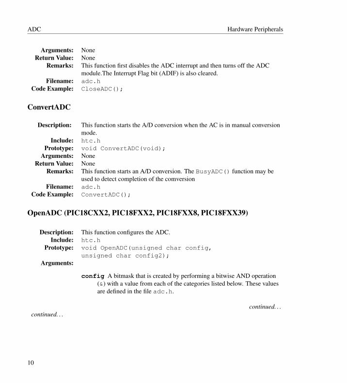
Arguments: NoneReturn Value: None
Remarks: This function first disables the ADC interrupt and then turns off the ADCmodule.The Interrupt Flag bit (ADIF) is also cleared.
Filename: adc.hCode Example: CloseADC();
ConvertADC
Description: This function starts the A/D conversion when the AC is in manual conversionmode.
Include: htc.hPrototype: void ConvertADC(void);
Arguments: NoneReturn Value: None
Remarks: This function starts an A/D conversion. The BusyADC() function may beused to detect completion of the comversion
Filename: adc.hCode Example: ConvertADC();
OpenADC (PIC18CXX2, PIC18FXX2, PIC18FXX8, PIC18FXX39)
Description: This function configures the ADC.Include: htc.h
Prototype: void OpenADC(unsigned char config,unsigned char config2);
Arguments:
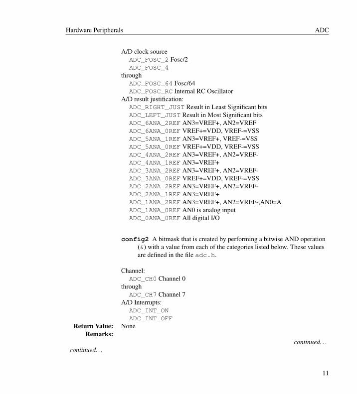
config A bitmask that is created by performing a bitwise AND operation(&) with a value from each of the categories listed below. These valuesare defined in the file adc.h.
continued. . .continued. . .
10
Hardware Peripherals ADC
A/D clock sourceADC_FOSC_2 Fosc/2ADC_FOSC_4
throughADC_FOSC_64 Fosc/64ADC_FOSC_RC Internal RC Oscillator
A/D result justification:ADC_RIGHT_JUST Result in Least Significant bitsADC_LEFT_JUST Result in Most Significant bitsADC_6ANA_2REF AN3=VREF+, AN2=VREFADC_6ANA_0REF VREF+=VDD, VREF-=VSSADC_5ANA_1REF AN3=VREF+, VREF-=VSSADC_5ANA_0REF VREF+=VDD, VREF-=VSSADC_4ANA_2REF AN3=VREF+, AN2=VREF-ADC_4ANA_1REF AN3=VREF+ADC_3ANA_2REF AN3=VREF+, AN2=VREF-ADC_3ANA_0REF VREF+=VDD, VREF-=VSSADC_2ANA_2REF AN3=VREF+, AN2=VREF-ADC_2ANA_1REF AN3=VREF+ADC_1ANA_2REF AN3=VREF+, AN2=VREF-,AN0=AADC_1ANA_0REF AN0 is analog inputADC_0ANA_0REF All digital I/O
config2 A bitmask that is created by performing a bitwise AND operation(&) with a value from each of the categories listed below. These valuesare defined in the file adc.h.
Channel:ADC_CH0 Channel 0
throughADC_CH7 Channel 7
A/D Interrupts:ADC_INT_ONADC_INT_OFF
Return Value: NoneRemarks:
continued. . .continued. . .
11

ADC Hardware Peripherals
Filename: adcopen.cCode Example: OpenADC( ADC_FOSC_32 & ADC_RIGHT_JUST &
ADC_1ANA_0REF, ADC_CH0 & ADC_INT_OFF);
OpenADC (PIC18C658/858, PIC18C601/801, PIC18F6X20, PIC18F8X20)
Description: This function configures the ADC.Include: htc.h
Prototype: void OpenADC(unsigned char config,unsigned char config2);
Arguments:
config A bitmask that is created by performing a bitwise AND operation(&) with a value from each of the categories listed below. These valuesare defined in the file adc.h.
A/D clock sourceADC_FOSC_2 Fosc/2ADC_FOSC_4
throughADC_FOSC_64 Fosc/64ADC_FOSC_RC Internal RC Oscillator
A/D result justification:ADC_RIGHT_JUST Result in Least Significant bitsADC_LEFT_JUST Result in Most Significant bits
continued. . .continued. . .
12
Hardware Peripherals ADC
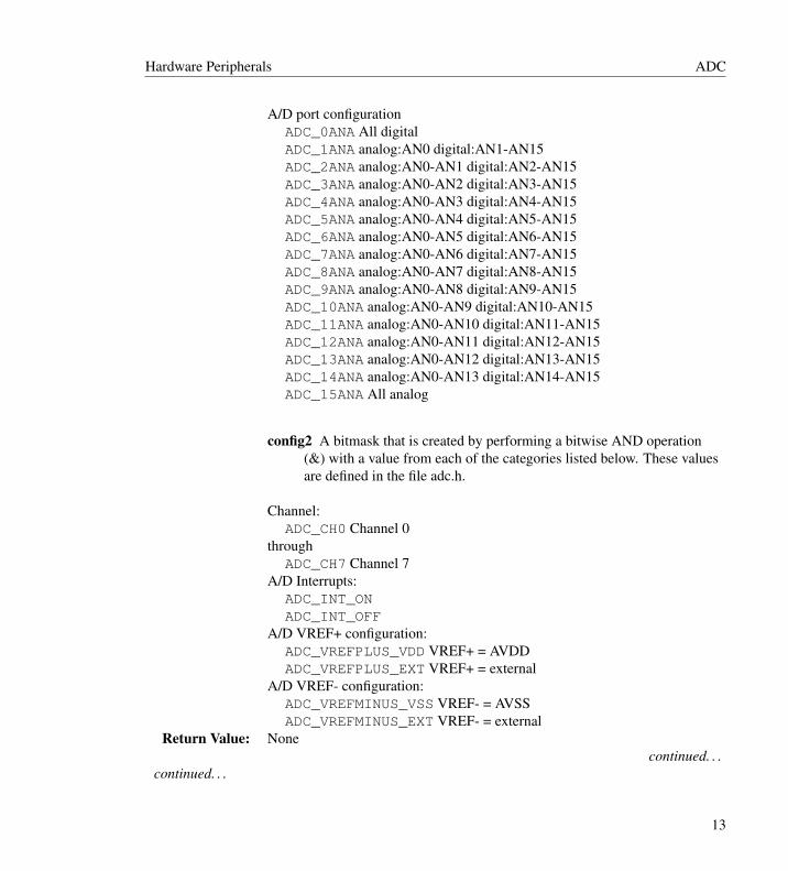
A/D port configurationADC_0ANA All digitalADC_1ANA analog:AN0 digital:AN1-AN15ADC_2ANA analog:AN0-AN1 digital:AN2-AN15ADC_3ANA analog:AN0-AN2 digital:AN3-AN15ADC_4ANA analog:AN0-AN3 digital:AN4-AN15ADC_5ANA analog:AN0-AN4 digital:AN5-AN15ADC_6ANA analog:AN0-AN5 digital:AN6-AN15ADC_7ANA analog:AN0-AN6 digital:AN7-AN15ADC_8ANA analog:AN0-AN7 digital:AN8-AN15ADC_9ANA analog:AN0-AN8 digital:AN9-AN15ADC_10ANA analog:AN0-AN9 digital:AN10-AN15ADC_11ANA analog:AN0-AN10 digital:AN11-AN15ADC_12ANA analog:AN0-AN11 digital:AN12-AN15ADC_13ANA analog:AN0-AN12 digital:AN13-AN15ADC_14ANA analog:AN0-AN13 digital:AN14-AN15ADC_15ANA All analog
config2 A bitmask that is created by performing a bitwise AND operation(&) with a value from each of the categories listed below. These valuesare defined in the file adc.h.
Channel:ADC_CH0 Channel 0
throughADC_CH7 Channel 7
A/D Interrupts:ADC_INT_ONADC_INT_OFF
A/D VREF+ configuration:ADC_VREFPLUS_VDD VREF+ = AVDDADC_VREFPLUS_EXT VREF+ = external
A/D VREF- configuration:ADC_VREFMINUS_VSS VREF- = AVSSADC_VREFMINUS_EXT VREF- = external
Return Value: Nonecontinued. . .
continued. . .
13

ADC Hardware Peripherals
Remarks: This function resets the A/D-related registers to the POR state and thenconfigures the clock, result format, voltage reference, port and channel.
Filename: adcopen.cCode Example: OpenADC( ADC_FOSC_32 & ADC_RIGHT_JUST & ADC_14ANA,
ADC_CH0 & ADC_INT_OFF);
OpenADC (All other processors)
Description: This function configures the ADC.Include: htc.h
Prototype: void OpenADC(unsigned char config,unsigned char config2,
unsigned char portconfig);Arguments:
config A bitmask that is created by performing a bitwise AND operation(&) with a value from each of the categories listed below. These valuesare defined in the file adc.h.
A/D clock sourceADC_FOSC_2 Fosc/2ADC_FOSC_4
throughADC_FOSC_64 Fosc/64ADC_FOSC_RC Internal RC Oscillator
A/D result justification:ADC_RIGHT_JUST Result in Least Significant bitsADC_LEFT_JUST Result in Most Significant bits
A/D acquisition time selectADC_0_TAD 0 TadADC_2_TAD 2 TadADC_4_TAD 4 TadADC_6_TAD 6 TadADC_8_TAD 8 TadADC_12_TAD 12 TadADC_16_TAD 16 TadADC_20_TAD 20 Tad
continued. . .continued. . .
14
Hardware Peripherals ADC
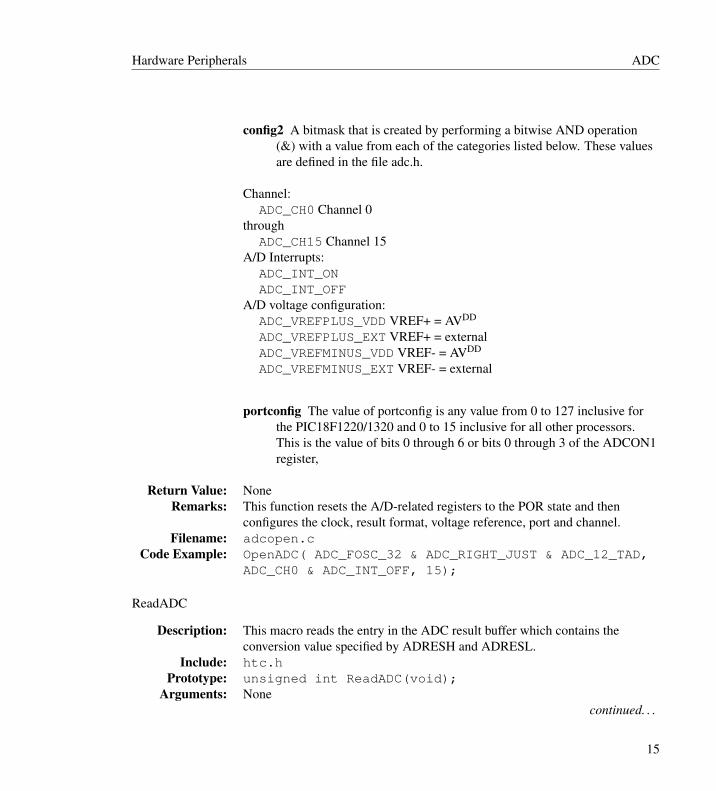
config2 A bitmask that is created by performing a bitwise AND operation(&) with a value from each of the categories listed below. These valuesare defined in the file adc.h.
Channel:ADC_CH0 Channel 0
throughADC_CH15 Channel 15
A/D Interrupts:ADC_INT_ONADC_INT_OFF
A/D voltage configuration:ADC_VREFPLUS_VDD VREF+ = AVDD
ADC_VREFPLUS_EXT VREF+ = externalADC_VREFMINUS_VDD VREF- = AVDD
ADC_VREFMINUS_EXT VREF- = external
portconfig The value of portconfig is any value from 0 to 127 inclusive forthe PIC18F1220/1320 and 0 to 15 inclusive for all other processors.This is the value of bits 0 through 6 or bits 0 through 3 of the ADCON1register,
Return Value: NoneRemarks: This function resets the A/D-related registers to the POR state and then
configures the clock, result format, voltage reference, port and channel.Filename: adcopen.c
Code Example: OpenADC( ADC_FOSC_32 & ADC_RIGHT_JUST & ADC_12_TAD,ADC_CH0 & ADC_INT_OFF, 15);
ReadADC
Description: This macro reads the entry in the ADC result buffer which contains theconversion value specified by ADRESH and ADRESL.
Include: htc.hPrototype: unsigned int ReadADC(void);
Arguments: Nonecontinued. . .
15

ADC Hardware Peripherals
Return Value: The correcsponding entry from the ADC result bufferRemarks: This function returns the contents of the ADC Buffer register.
Code Example: unsigned int result;result = ReadADC();
SetChanADC
Description: This function sets the positive and negative inputs for the sample multiplexersA and B for manual and alternate sample modes.
Include: htc.hPrototype: SetChanADC(unsigned int channel);
Arguments:
channel This contains the bit fields that make up the parameter. A logicalOR is used to combine multiple bit fields together.
A/D Channel 0 positive input select for Sample AADC_CH0_POS_SAMPLEA_AN0
throughADC_CH0_POS_SAMPLEA_AN15
(These bit fields are mutually exclusive)A/D Channel 0 negative input select for Sample A
ADC_CH0_NEG_SAMPLEA_AN1ADC_CH0_NEG_SAMPLEA_NVREF
(These bit fields are mutually exclusive)n A/D Channel 0 positive input select for Sample B
ADC_CH0_POS_SAMPLEB_AN0through
ADC_CH0_POS_SAMPLEB_AN15(These bit fields are mutually exclusive)A/D Channel 0 negative input select for Sample B
ADC_CH0_NEG_SAMPLEB_AN1ADC_CH0_NEG_SAMPLEB_NVREF
(These bit fields are mutually exclusive)Return Value: None
continued. . .
16

Hardware Peripherals Input Capture
Remarks: This function configures the inputs for sample multiplexers A and B bywriting to ADCHS register. This macro is intended for use when configuringthe positive inputs when not using scan mode. This macro can be used toconfigure the negative input for the ADC in all modes of operation.
Code Example: SetChanADC(ADC_CH0_POS_SAMPLEA_AN0 |ADC_CH0_NEG_SAMPLEA_NVREF);
2.1.2 Example of Use
// <htc.h> will automatically include peripheral library header files when --runtime=+plib is used.#include <htc.h>int result;void main(void){// Configure ADCOpenADC(ADC_FOSC_32 & ADC_RIGHT_JUST & ADC_8ANA_0REF & ADC_CH0 & ADC_INT_OFF);delay(50); // Delay for 50 cyclesConvertADC(); // Start conversionwhile (BusyADC()); //Wait for completionresult = ReadADC(); // Read ResultCloseADC(); // Disable ADC}
2.2 Input Capture
2.2.1 Input Capture FunctionsThe capture peripheral is supported with the following functions
CloseCapture1CloseCapture2CloseCapture3CloseCapture4CloseCapture5CloseECapture1
17
Input Capture Hardware Peripherals
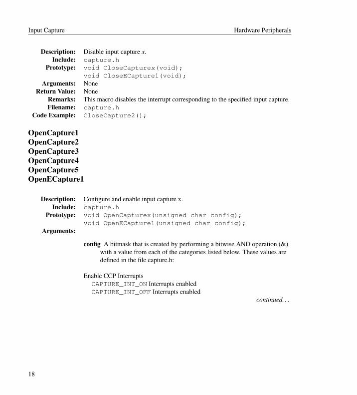
Description: Disable input capture x.Include: capture.h
Prototype: void CloseCapturex(void);void CloseECapture1(void);
Arguments: NoneReturn Value: None
Remarks: This macro disables the interrupt corresponding to the specified input capture.Filename: capture.h
Code Example: CloseCapture2();
OpenCapture1OpenCapture2OpenCapture3OpenCapture4OpenCapture5OpenECapture1
Description: Configure and enable input capture x.Include: capture.h
Prototype: void OpenCapturex(unsigned char config);void OpenECapture1(unsigned char config);
Arguments:
config A bitmask that is created by performing a bitwise AND operation (&)with a value from each of the categories listed below. These values aredefined in the file capture.h:
Enable CCP InterruptsCAPTURE_INT_ON Interrupts enabledCAPTURE_INT_OFF Interrupts enabled
continued. . .
18
Hardware Peripherals Input Capture
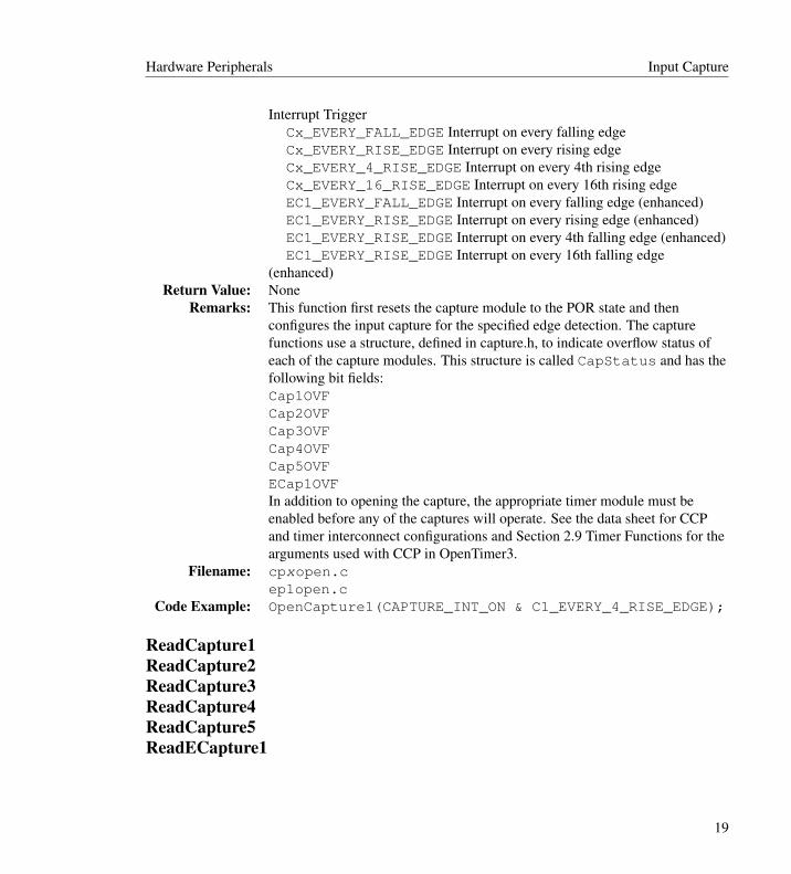
Interrupt TriggerCx_EVERY_FALL_EDGE Interrupt on every falling edgeCx_EVERY_RISE_EDGE Interrupt on every rising edgeCx_EVERY_4_RISE_EDGE Interrupt on every 4th rising edgeCx_EVERY_16_RISE_EDGE Interrupt on every 16th rising edgeEC1_EVERY_FALL_EDGE Interrupt on every falling edge (enhanced)EC1_EVERY_RISE_EDGE Interrupt on every rising edge (enhanced)EC1_EVERY_RISE_EDGE Interrupt on every 4th falling edge (enhanced)EC1_EVERY_RISE_EDGE Interrupt on every 16th falling edge
(enhanced)Return Value: None
Remarks: This function first resets the capture module to the POR state and thenconfigures the input capture for the specified edge detection. The capturefunctions use a structure, defined in capture.h, to indicate overflow status ofeach of the capture modules. This structure is called CapStatus and has thefollowing bit fields:Cap1OVFCap2OVFCap3OVFCap4OVFCap5OVFECap1OVFIn addition to opening the capture, the appropriate timer module must beenabled before any of the captures will operate. See the data sheet for CCPand timer interconnect configurations and Section 2.9 Timer Functions for thearguments used with CCP in OpenTimer3.
Filename: cpxopen.cep1open.c
Code Example: OpenCapture1(CAPTURE_INT_ON & C1_EVERY_4_RISE_EDGE);
ReadCapture1ReadCapture2ReadCapture3ReadCapture4ReadCapture5ReadECapture1
19

Input Capture Hardware Peripherals
Description: Read the result of a capture event from the specified input capture.Include: capture.h
Prototype: unsigned int ReadCapturex(void);unsigned int ReadECapture1(void);
Arguments: NoneReturn Value: This function returns the result of the capture event.
Remarks: This function reads the value of the respective input capture’s SFRs.Filename: cpxread.c
ep1read.cCode Example: ConvertADC();
2.2.2 Example of UseThis example demonstrates the use of the capture library routines in a polled (not interrupt-driven)environment.
// <htc.h> will automatically include peripheral library header files when --runtime=+plib is used.#include <htc.h>#include <stdlib.h>void main(void){
unsigned int result;char str[7];// Configure Capture1OpenCapture1( C1_EVERY_4_RISE_EDGE &
CAPTURE_INT_OFF );// Configure Timer3OpenTimer3( TIMER_INT_OFF &
T3_SOURCE_INT );// Configure USARTOpenUSART( USART_TX_INT_OFF &
USART_RX_INT_OFF &USART_ASYNCH_MODE &USART_EIGHT_BIT &USART_CONT_RX,25 );
while(!PIR1bits.CCP1IF); // Wait for eventresult = ReadCapture1(); // read resultultoa(result,str); // convert to string
20

Hardware Peripherals I2C
// Write the string out to the USART if// an overflow condition has not occurred.if(!CapStatus.Cap1OVF){
putsUSART(str);}// Clean upCloseCapture1();CloseTimer3();CloseUSART();
}
2.3 I2C
2.3.1 I2C Functions
AckI2CAckI2C1AckI2C2
Description: Generate I2C bus Acknowledge condition.Include: i2c.h
Prototype: void AckI2C(void);void AckI2C1(void);void AckI2C2(void);
Arguments: NoneReturn Value: None
Remarks: This macro generates an I2Cx bus Acknowledge condition.Filename: i2c_.h
Code Example: AckI2C();
CloseI2CCloseI2C1CloseI2C2
Description: Disable the SSPx module.continued. . .
21
I2C Hardware Peripherals
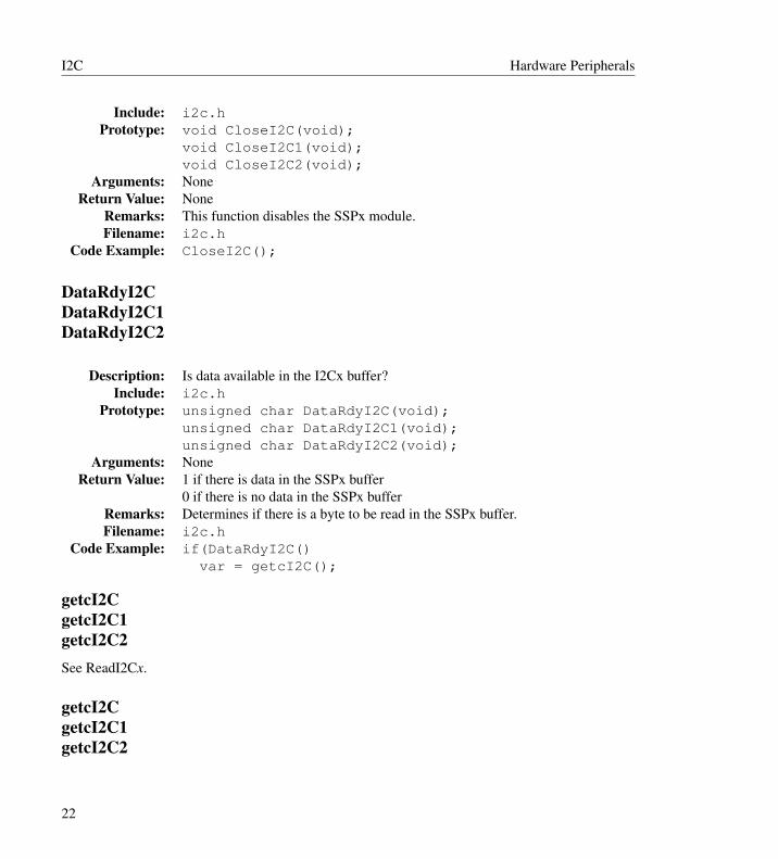
Include: i2c.hPrototype: void CloseI2C(void);
void CloseI2C1(void);void CloseI2C2(void);
Arguments: NoneReturn Value: None
Remarks: This function disables the SSPx module.Filename: i2c.h
Code Example: CloseI2C();
DataRdyI2CDataRdyI2C1DataRdyI2C2
Description: Is data available in the I2Cx buffer?Include: i2c.h
Prototype: unsigned char DataRdyI2C(void);unsigned char DataRdyI2C1(void);unsigned char DataRdyI2C2(void);
Arguments: NoneReturn Value: 1 if there is data in the SSPx buffer
0 if there is no data in the SSPx bufferRemarks: Determines if there is a byte to be read in the SSPx buffer.Filename: i2c.h
Code Example: if(DataRdyI2C()var = getcI2C();
getcI2CgetcI2C1getcI2C2See ReadI2Cx.
getcI2CgetcI2C1getcI2C2
22
Hardware Peripherals I2C
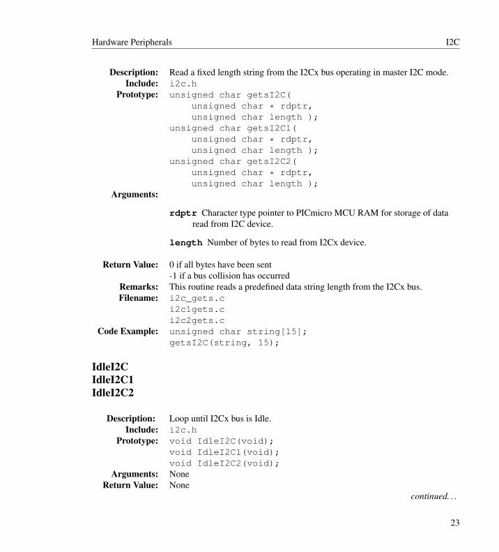
Description: Read a fixed length string from the I2Cx bus operating in master I2C mode.Include: i2c.h
Prototype: unsigned char getsI2C(unsigned char * rdptr,unsigned char length );
unsigned char getsI2C1(unsigned char * rdptr,unsigned char length );
unsigned char getsI2C2(unsigned char * rdptr,unsigned char length );
Arguments:
rdptr Character type pointer to PICmicro MCU RAM for storage of dataread from I2C device.
length Number of bytes to read from I2Cx device.
Return Value: 0 if all bytes have been sent-1 if a bus collision has occurred
Remarks: This routine reads a predefined data string length from the I2Cx bus.Filename: i2c_gets.c
i2c1gets.ci2c2gets.c
Code Example: unsigned char string[15];getsI2C(string, 15);
IdleI2CIdleI2C1IdleI2C2
Description: Loop until I2Cx bus is Idle.Include: i2c.h
Prototype: void IdleI2C(void);void IdleI2C1(void);void IdleI2C2(void);
Arguments: NoneReturn Value: None
continued. . .
23
I2C Hardware Peripherals
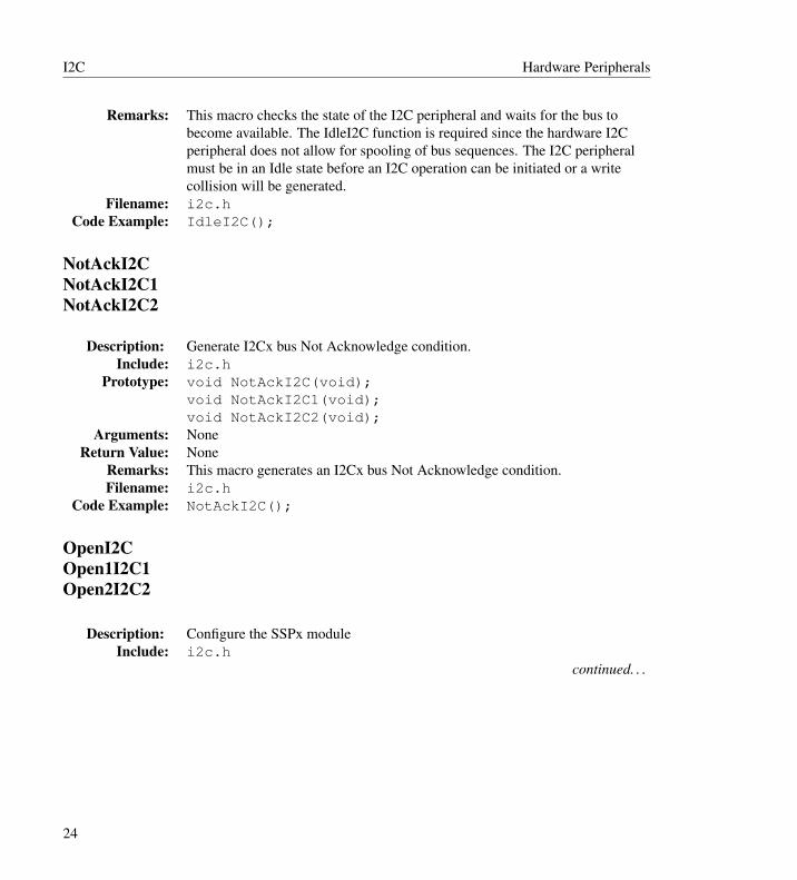
Remarks: This macro checks the state of the I2C peripheral and waits for the bus tobecome available. The IdleI2C function is required since the hardware I2Cperipheral does not allow for spooling of bus sequences. The I2C peripheralmust be in an Idle state before an I2C operation can be initiated or a writecollision will be generated.
Filename: i2c.hCode Example: IdleI2C();
NotAckI2CNotAckI2C1NotAckI2C2
Description: Generate I2Cx bus Not Acknowledge condition.Include: i2c.h
Prototype: void NotAckI2C(void);void NotAckI2C1(void);void NotAckI2C2(void);
Arguments: NoneReturn Value: None
Remarks: This macro generates an I2Cx bus Not Acknowledge condition.Filename: i2c.h
Code Example: NotAckI2C();
OpenI2COpen1I2C1Open2I2C2
Description: Configure the SSPx moduleInclude: i2c.h
continued. . .
24
Hardware Peripherals I2C
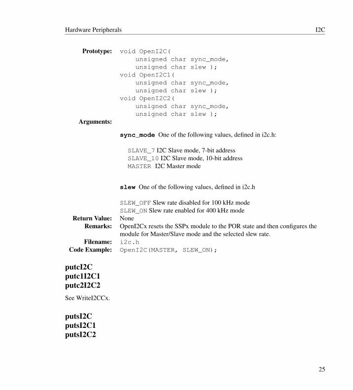
Prototype: void OpenI2C(unsigned char sync_mode,unsigned char slew );
void OpenI2C1(unsigned char sync_mode,unsigned char slew );
void OpenI2C2(unsigned char sync_mode,unsigned char slew );
Arguments:
sync_mode One of the following values, defined in i2c.h:
SLAVE_7 I2C Slave mode, 7-bit addressSLAVE_10 I2C Slave mode, 10-bit addressMASTER I2C Master mode
slew One of the following values, defined in i2c.h
SLEW_OFF Slew rate disabled for 100 kHz modeSLEW_ON Slew rate enabled for 400 kHz mode
Return Value: NoneRemarks: OpenI2Cx resets the SSPx module to the POR state and then configures the
module for Master/Slave mode and the selected slew rate.Filename: i2c.h
Code Example: OpenI2C(MASTER, SLEW_ON);
putcI2Cputc1I2C1putc2I2C2See WriteI2CCx.
putsI2CputsI2C1putsI2C2
25

I2C Hardware Peripherals
Description: Write a data string to the I2Cx bus operating in either Master or Slave mode.Include: i2c.h
Prototype: unsigned char putsI2C(unsigned char * wrptr,
unsigned char putsI2C1(unsigned char * wrptr,
unsigned char putsI2C2(unsigned char * wrptr,
Arguments:
wrptr Pointer to data that will be written to the I2C bus.
Return Value: Master I2C Mode0 if the null character was reached in the data string-2 if the slave I2Cx device responded with a NOT ACK-3 if a write collision occurredSlave I2C Mode0 if the null character was reached in the data string -2 if the master I2Cxdevice responded with a NOT ACK which terminated the data transfer
Remarks: This routine puts a predefined data string length on the I2Cx bus.Filename: i2c_puts.c
i2c1puts.ci2c2puts.c
Code Example: unsigned char string[] = “data to send”;putsI2C(string);
ReadI2CReadI2C1ReadI2C2getI2CgetI2C1getI2C2
Description: Read a single byte from the I2Cx bus.Include: i2c.h
continued. . .
26

Hardware Peripherals I2C
Prototype: unsigned char ReadI2C(void);unsigned char ReadI2C1(void);unsigned char ReadI2C2(void);
Arguments: NoneReturn Value: The byte read from the I2Cx bus.
Remarks: This function reads in a single byte from the I2Cx bus. getcI2Cx is defined tobe ReadI2Cx in i2c.h, and have the same prototype and function.
Filename: i2c_read.ci2c1read.ci2c2read.c
Code Example: unsigned char valuevalue = ReadI2C();
RestartI2CRestartI2C1RestartI2C2
Description: Generate an I2Cx bus restart condition.Include: i2c.h
Prototype: void RestartI2C(void);void RestartI2C1(void);void RestartI2C2(void);
Arguments: NoneReturn Value: None
Remarks: This macro generates an I2Cx bus Restart condition.Filename: i2c.h
Code Example: RestartI2C();
StartI2CStartI2C1StartI2C2
Description: Generate an I2Cx bus Start condition.Include: i2c.h
Prototype: void StartI2C(void);void StartI2C1(void);void StartI2C2(void);
continued. . .
27
I2C Hardware Peripherals
Arguments: NoneReturn Value: None
Remarks: This macro generates an I2Cx bus Start condition.Filename: i2c.h
Code Example: StartI2C();
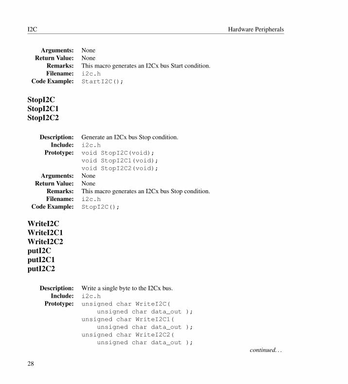
StopI2CStopI2C1StopI2C2
Description: Generate an I2Cx bus Stop condition.Include: i2c.h
Prototype: void StopI2C(void);void StopI2C1(void);void StopI2C2(void);
Arguments: NoneReturn Value: None
Remarks: This macro generates an I2Cx bus Stop condition.Filename: i2c.h
Code Example: StopI2C();
WriteI2CWriteI2C1WriteI2C2putI2CputI2C1putI2C2
Description: Write a single byte to the I2Cx bus.Include: i2c.h
Prototype: unsigned char WriteI2C(unsigned char data_out );
unsigned char WriteI2C1(unsigned char data_out );
unsigned char WriteI2C2(unsigned char data_out );
continued. . .
28
Hardware Peripherals I2C
Arguments:
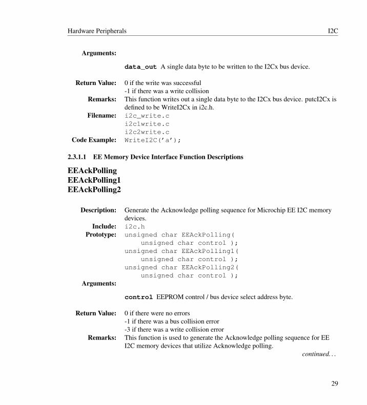
data_out A single data byte to be written to the I2Cx bus device.
Return Value: 0 if the write was successful-1 if there was a write collision
Remarks: This function writes out a single data byte to the I2Cx bus device. putcI2Cx isdefined to be WriteI2Cx in i2c.h.
Filename: i2c_write.ci2c1write.ci2c2write.c
Code Example: WriteI2C(’a’);
2.3.1.1 EE Memory Device Interface Function Descriptions
EEAckPollingEEAckPolling1EEAckPolling2
Description: Generate the Acknowledge polling sequence for Microchip EE I2C memorydevices.
Include: i2c.hPrototype: unsigned char EEAckPolling(
unsigned char control );unsigned char EEAckPolling1(
unsigned char control );unsigned char EEAckPolling2(
unsigned char control );Arguments:
control EEPROM control / bus device select address byte.
Return Value: 0 if there were no errors-1 if there was a bus collision error-3 if there was a write collision error
Remarks: This function is used to generate the Acknowledge polling sequence for EEI2C memory devices that utilize Acknowledge polling.
continued. . .
29

I2C Hardware Peripherals
Filename: i2c_ecap.ci2c1ecap.ci2c2ecap.c
Code Example: temp = EEAckPolling(0xA0);
EEByteWriteEEByteWrite1EEByteWrite2
Description: Write a single byte to the I2Cx bus.Include: i2c.h
Prototype: void EEByteWrite(unsigned char control,unsigned char address,unsigned char data );
void EEByteWrite1(unsigned char control,unsigned char address,unsigned char data );
void EEByteWrite2(unsigned char control,unsigned char address,unsigned char data );
Arguments:
control EEPROM control / bus device select address byte.
address EEPROM internal address location.
data Data to write to EEPROM address specified in function parameteraddress.
Return Value: -1 if there was a bus collision error-2 if there was a NOT ACK error-3 if there was a write collision error
Remarks: This function writes a single data byte to the I2Cx bus. This routine can beused for any Microchip I2C EE memory device which requires only 1 byte ofaddress information.
continued. . .
30
Hardware Peripherals I2C
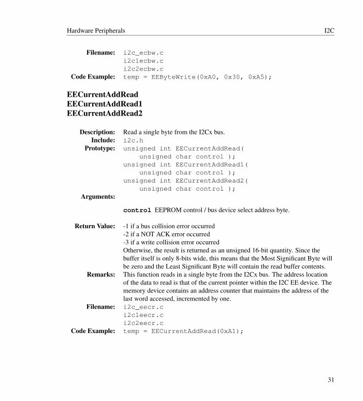
Filename: i2c_ecbw.ci2c1ecbw.ci2c2ecbw.c
Code Example: temp = EEByteWrite(0xA0, 0x30, 0xA5);
EECurrentAddReadEECurrentAddRead1EECurrentAddRead2
Description: Read a single byte from the I2Cx bus.Include: i2c.h
Prototype: unsigned int EECurrentAddRead(unsigned char control );
unsigned int EECurrentAddRead1(unsigned char control );
unsigned int EECurrentAddRead2(unsigned char control );
Arguments:
control EEPROM control / bus device select address byte.
Return Value: -1 if a bus collision error occurred-2 if a NOT ACK error occurred-3 if a write collision error occurredOtherwise, the result is returned as an unsigned 16-bit quantity. Since thebuffer itself is only 8-bits wide, this means that the Most Significant Byte willbe zero and the Least Significant Byte will contain the read buffer contents.
Remarks: This function reads in a single byte from the I2Cx bus. The address locationof the data to read is that of the current pointer within the I2C EE device. Thememory device contains an address counter that maintains the address of thelast word accessed, incremented by one.
Filename: i2c_eecr.ci2c1eecr.ci2c2eecr.c
Code Example: temp = EECurrentAddRead(0xA1);
31

I2C Hardware Peripherals
EEPageWriteEEPageWrite1EEPageWrite2
Description: Write a string of data to the EE device from the I2Cx bus.Include: i2c.h
Prototype: unsigned char EEPageWrite(unsigned char control,unsigned char address,unsigned char * wrptr );
unsigned char EEPageWrite1(unsigned char control,unsigned char address,unsigned char * wrptr );
unsigned char EEPageWrite2(unsigned char control,unsigned char address,unsigned char * wrptr );
Arguments:
control EEPROM control / bus device select address byte.
address EEPROM internal address location.
wrptr Character type pointer in PICmicro MCU RAM. The data objectspointed to by wrptr will be written to the EE device.
Return Value: 0 if there were no errors-1 if there was a bus collision error-2 if there was a NOT ACK error-3 if there was a write collision error
Remarks: This function writes a null terminated string of data to the I2C EE memorydevice. The null character itself is not transmitted.
Filename: i2c_eepw.ci2c1eepw.ci2c2eepw.c
Code Example: temp = EEPageWrite(0xA0, 0x70, wrptr);
32
Hardware Peripherals I2C
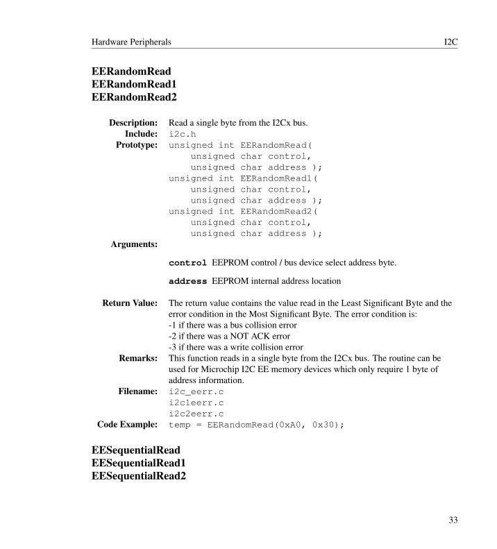
EERandomReadEERandomRead1EERandomRead2
Description: Read a single byte from the I2Cx bus.Include: i2c.h
Prototype: unsigned int EERandomRead(unsigned char control,unsigned char address );
unsigned int EERandomRead1(unsigned char control,unsigned char address );
unsigned int EERandomRead2(unsigned char control,unsigned char address );
Arguments:
control EEPROM control / bus device select address byte.
address EEPROM internal address location
Return Value: The return value contains the value read in the Least Significant Byte and theerror condition in the Most Significant Byte. The error condition is:-1 if there was a bus collision error-2 if there was a NOT ACK error-3 if there was a write collision error
Remarks: This function reads in a single byte from the I2Cx bus. The routine can beused for Microchip I2C EE memory devices which only require 1 byte ofaddress information.
Filename: i2c_eerr.ci2c1eerr.ci2c2eerr.c
Code Example: temp = EERandomRead(0xA0, 0x30);
EESequentialReadEESequentialRead1EESequentialRead2
33

I2C Hardware Peripherals
Description: Read a string of data from the I2Cx bus.Include: i2c.h
Prototype: unsigned char EEPageWrite(unsigned char control,unsigned char address,unsigned char * rdptr,unsigned char length );
unsigned char EEPageWrite1(unsigned char control,unsigned char address,unsigned char * rdptr );unsigned char length );
unsigned char EEPageWrite2(unsigned char control,unsigned char address,unsigned char * rdptr,unsigned char length );
Arguments:
control EEPROM control / bus device select address byte.
address EEPROM internal address location.
rdptr Character type pointer in PICmicro MCU RAM area for placementof data read from EEPROM device.
length Number of bytes to read from EEPROM device.
Return Value: 0 if there were no errors-1 if there was a bus collision error-2 if there was a NOT ACK error-3 if there was a write collision error
Remarks: This function reads in a predefined string length of data from the I2Cx bus.The routine can be used for Microchip I2C EE memory devices which onlyrequire 1 byte of address information.
Filename: i2c_eepw.ci2c1eepw.ci2c2eepw.c
Code Example: err = EESequentialRead(0xA0, 0x70, rdptr, 15);
34
Hardware Peripherals IO Ports
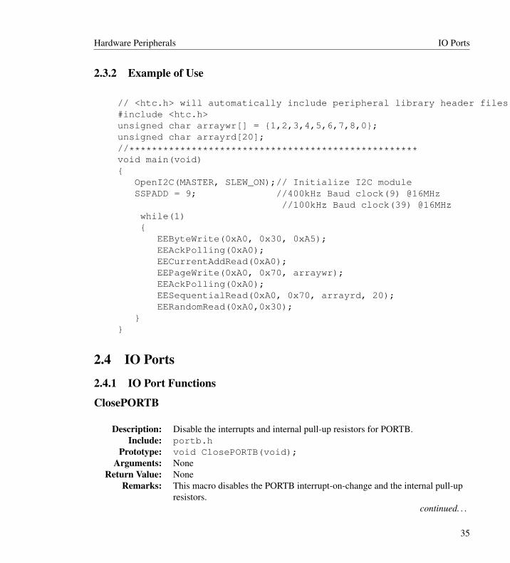
2.3.2 Example of Use
// <htc.h> will automatically include peripheral library header files when --runtime=+plib is used.#include <htc.h>unsigned char arraywr[] = {1,2,3,4,5,6,7,8,0};unsigned char arrayrd[20];//***************************************************void main(void){
OpenI2C(MASTER, SLEW_ON);// Initialize I2C moduleSSPADD = 9; //400kHz Baud clock(9) @16MHz
//100kHz Baud clock(39) @16MHzwhile(1){
EEByteWrite(0xA0, 0x30, 0xA5);EEAckPolling(0xA0);EECurrentAddRead(0xA0);EEPageWrite(0xA0, 0x70, arraywr);EEAckPolling(0xA0);EESequentialRead(0xA0, 0x70, arrayrd, 20);EERandomRead(0xA0,0x30);
}}
2.4 IO Ports
2.4.1 IO Port Functions
ClosePORTB
Description: Disable the interrupts and internal pull-up resistors for PORTB.Include: portb.h
Prototype: void ClosePORTB(void);Arguments: None
Return Value: NoneRemarks: This macro disables the PORTB interrupt-on-change and the internal pull-up
resistors.continued. . .
35

IO Ports Hardware Peripherals
Filename: portb.hCode Example: ClosePORTB();
CloseRB0INTCloseRB1INTCloseRB2INT
Description: Disable the interrupts for the specified PORTB pin.Include: portb.h
Prototype: void CloseRB0INT(void);void CloseRB1INT(void);void CloseRB2INT(void);
Arguments: NoneReturn Value: None
Remarks: This macro disables the PORTB interrupt-on-change.Filename: portb.h
Code Example: CloseRB0INT();
DisablePullups
Description: Disable the internal pull-up resistors on PORTB.Include: portb.h
Prototype: void DisablePullups(void);Arguments: None
Return Value: NoneRemarks: This macro disables the internal pull-up resistors on PORTB.Filename: portb.h
Code Example: DisablePullups();
EnablePullups
Description: Enable the internal pull-up resistors on PORTB.Include: portb.h
Prototype: void EnablePullups(void);Arguments: None
continued. . .
36
Hardware Peripherals IO Ports
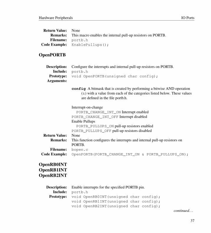
Return Value: NoneRemarks: This macro enables the internal pull-up resistors on PORTB.Filename: portb.h
Code Example: EnablePullups();
OpenPORTB
Description: Configure the interrupts and internal pull-up resistors on PORTB.Include: portb.h
Prototype: void OpenPORTB(unsigned char config);Arguments:
config A bitmask that is created by performing a bitwise AND operation(&) with a value from each of the categories listed below. These valuesare defined in the file portb.h.
Interrupt-on-changePORTB_CHANGE_INT_ON Interrupt enabled
PORTB_CHANGE_INT_OFF Interrupt disabledEnable Pullups
PORTB_PULLUPS_ON pull-up resistors enabledPORTB_PULLUPS_OFF pull-up resistors disabled
Return Value: NoneRemarks: This function configures the interrupts and internal pull-up resistors on
PORTB.Filename: bopen.c
Code Example: OpenPORTB(PORTB_CHANGE_INT_ON & PORTB_PULLUPS_ON);
OpenRB0INTOpenRB1INTOpenRB2INT
Description: Enable interrupts for the specified PORTB pin.Include: portb.h
Prototype: void OpenRB0INT(unsigned char config);void OpenRB1INT(unsigned char config);void OpenRB2INT(unsigned char config);
continued. . .
37

Microwire Hardware Peripherals
Arguments:
config A bitmask that is created by performing a bitwise AND operation(&) with a value from each of the categories listed below. These valuesare defined in the file portb.h.
Interrupt-on-changePORTB_CHANGE_INT_ON Interrupt enabled
PORTB_CHANGE_INT_OFF Interrupt disabledInterrupt-on-edge
RISING_EDGE_INT Interrupt on rising edgeFALLING_EDGE_INT Interrupt on falling edge
Enable PullupsPORTB_PULLUPS_ON pull-up resistors enabled
PORTB_PULLUPS_OFF pull-up resistors disabledReturn Value: None
Remarks: This function configures the interrupts and internal pull-up resistors onPORTB.
Filename: bopen.c
Code Example: OpenRB0INT(PORTB_CHANGE_INT_ON & RISING_EDGE_INT &PORTB_PULLUPS_ON);
2.5 Microwire
2.5.1 Microwire Functions
CloseMwireCloseMwire1CloseMwire2
Description: Disable the SSPx module.Include: mwire.h
Prototype: void CloseMwire(void);void CloseMwire1(void);void CloseMwire2(void);
continued. . .
38

Hardware Peripherals Microwire
Arguments: NoneReturn Value: None
Remarks: Pin I/O returns under control of the TRISC and LATC register settings.Filename: mw_close.c
mw1close.cmwire.h
Code Example: CloseMwire();
DataRdyMwireDataRdyMwire1DataRdyMwire2
Description: Indicate whether the Microwirex device has completed the internal writecycle.
Include: mwire.hPrototype: unsigned char DataRdyMwire(void);
unsigned char DataRdyMwire1(void);unsigned char DataRdyMwire2(void);
Arguments: NoneReturn Value: 1 if the Microwirex device is ready
0 if the internal write cycle is not complete or a bus error occurredRemarks: Determines if Microwirex device is ready.Filename: mwire.h
Code Example: while( ! DataRdyMwire())continue;
getcMwiregetcMwire1getcMwire2See ReadMwirex.
getsMwiregetsMwire1getsMwire2
39
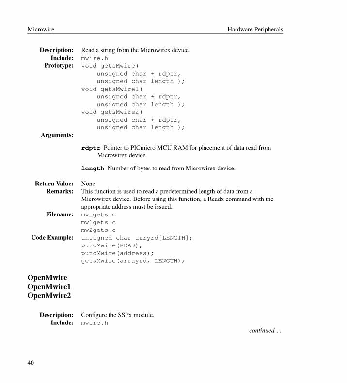
Microwire Hardware Peripherals
Description: Read a string from the Microwirex device.Include: mwire.h
Prototype: void getsMwire(unsigned char * rdptr,unsigned char length );
void getsMwire1(unsigned char * rdptr,unsigned char length );
void getsMwire2(unsigned char * rdptr,unsigned char length );
Arguments:
rdptr Pointer to PICmicro MCU RAM for placement of data read fromMicrowirex device.
length Number of bytes to read from Microwirex device.
Return Value: NoneRemarks: This function is used to read a predetermined length of data from a
Microwirex device. Before using this function, a Readx command with theappropriate address must be issued.
Filename: mw_gets.cmw1gets.cmw2gets.c
Code Example: unsigned char arryrd[LENGTH];putcMwire(READ);putcMwire(address);getsMwire(arrayrd, LENGTH);
OpenMwireOpenMwire1OpenMwire2
Description: Configure the SSPx module.Include: mwire.h
continued. . .
40

Hardware Peripherals Microwire
Prototype: void OpenMwire(unsigned char sync_mode);
void getsMwire1(unsigned char sync_mode);
void getsMwire2(unsigned char sync_mode);
Arguments:
sync_mode One of the following values defined in mwire.h:
MWIRE_FOSC_4 clock = FOSC/4MWIRE_FOSC_16 clock = FOSC/16MWIRE_FOSC_64 clock = FOSC/64MWIRE_FOSC_TMR2 clock = TMR2 output/2
Return Value: NoneRemarks: OpenMwirex resets the SSPx module to the POR state and then configures the
module for Microwire communications.Filename: mwire.h
Code Example: OpenMwire(MWIRE_FOSC_16);
putcMwireputcMwire1putcMwire2See WriteMwirex.
ReadMwireReadMwire1ReadMwire2getcMwiregetcMwire1getcMwire2
Description: Read a byte from the Microwirex device.Include: mwire.h
continued. . .
41
Microwire Hardware Peripherals
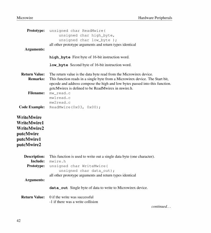
Prototype: unsigned char ReadMwire(unsigned char high_byte,unsigned char low_byte );
all other prototype arguments and return types identicalArguments:
high_byte First byte of 16-bit instruction word.
low_byte Second byte of 16-bit instruction word.
Return Value: The return value is the data byte read from the Microwirex device.Remarks: This function reads in a single byte from a Microwirex device. The Start bit,
opcode and address compose the high and low bytes passed into this function.getcMwirex is defined to be ReadMwirex in mwire.h.
Filename: mw_read.cmw1read.cmw2read.c
Code Example: ReadMwire(0x03, 0x00);
WriteMwireWriteMwire1WriteMwire2putcMwireputcMwire1putcMwire2
Description: This function is used to write out a single data byte (one character).Include: mwire.h
Prototype: unsigned char WriteMwire(unsigned char data_out);
all other prototype arguments and return types identicalArguments:
data_out Single byte of data to write to Microwirex device.
Return Value: 0 if the write was successful-1 if there was a write collision
continued. . .
42

Hardware Peripherals Microwire
Remarks: This function writes out single data byte to a Microwirex device utilizing theSSPx module. putcMwirex is defined to be WriteMwirex in mwire.h.
Filename: mw_write.cmw1write.cmw2write.c
Code Example: WriteMwire(0x55);
2.5.2 Example of UseThe following is a simple code example illustrating the SSP module communicating with a Mi-crochip 93LC66 Microwire EE memory device.
// <htc.h> will automatically include peripheral library header files when --runtime=+plib is used.#include <htc.h>// 93LC66 x 8// FUNCTION Prototypesvoid main(void);void ew_enable(void);void erase_all(void);void busy_poll(void);void write_all(unsigned char data);void byte_read(unsigned char address);void read_mult(unsigned char address,
unsigned char *rdptr,unsigned char length);
void write_byte(unsigned char address,unsigned char data);
// VARIABLE Definitionsunsigned char arrayrd[20];unsigned char var;// DEFINE 93LC66 MACROS -- see datasheet for details#define READ 0x0C#define WRITE 0x0A#define ERASE 0x0E#define EWEN1 0x09#define EWEN2 0x80#define ERAL1 0x09#define ERAL2 0x00#define WRAL1 0x08
43
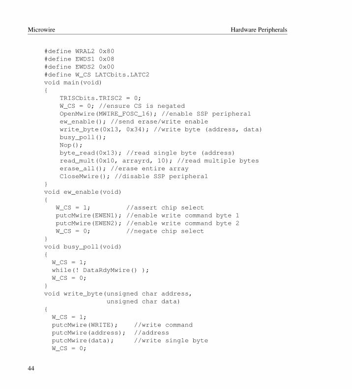
Microwire Hardware Peripherals
#define WRAL2 0x80#define EWDS1 0x08#define EWDS2 0x00#define W_CS LATCbits.LATC2void main(void){
TRISCbits.TRISC2 = 0;W_CS = 0; //ensure CS is negatedOpenMwire(MWIRE_FOSC_16); //enable SSP peripheralew_enable(); //send erase/write enablewrite_byte(0x13, 0x34); //write byte (address, data)busy_poll();Nop();byte_read(0x13); //read single byte (address)read_mult(0x10, arrayrd, 10); //read multiple byteserase_all(); //erase entire arrayCloseMwire(); //disable SSP peripheral
}void ew_enable(void){
W_CS = 1; //assert chip selectputcMwire(EWEN1); //enable write command byte 1putcMwire(EWEN2); //enable write command byte 2W_CS = 0; //negate chip select
}void busy_poll(void){
W_CS = 1;while(! DataRdyMwire() );W_CS = 0;
}void write_byte(unsigned char address,
unsigned char data){
W_CS = 1;putcMwire(WRITE); //write commandputcMwire(address); //addressputcMwire(data); //write single byteW_CS = 0;
44
Hardware Peripherals Pulse-Width Modulation
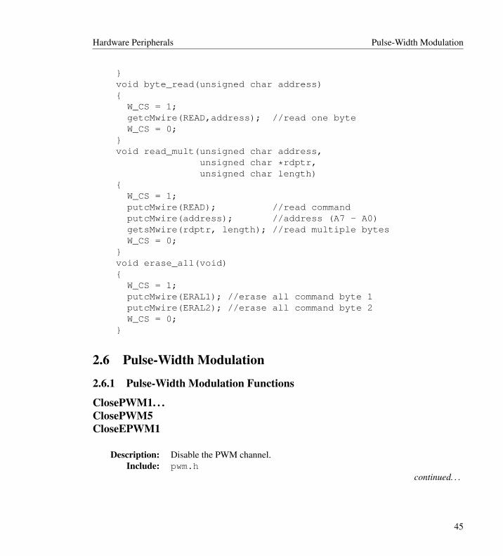
}void byte_read(unsigned char address){
W_CS = 1;getcMwire(READ,address); //read one byteW_CS = 0;
}void read_mult(unsigned char address,
unsigned char *rdptr,unsigned char length)
{W_CS = 1;putcMwire(READ); //read commandputcMwire(address); //address (A7 - A0)getsMwire(rdptr, length); //read multiple bytesW_CS = 0;
}void erase_all(void){
W_CS = 1;putcMwire(ERAL1); //erase all command byte 1putcMwire(ERAL2); //erase all command byte 2W_CS = 0;
}
2.6 Pulse-Width Modulation
2.6.1 Pulse-Width Modulation Functions
ClosePWM1. . .ClosePWM5CloseEPWM1
Description: Disable the PWM channel.Include: pwm.h
continued. . .
45

Pulse-Width Modulation Hardware Peripherals
Prototype: void ClosePWM1(void);...void ClosePWM5(void);void CloseEPWM1(void);
Arguments: NoneReturn Value: None
Remarks: This function disables the specified PWM channel.Filename: pw1close.c...
pwm.hCode Example: ClosePWM1();
OpenPWM1. . .OpenPWM5OpenEPWM1
Description: Configure the PWM channel.Include: pwm.h
Prototype: void OpenPWM1(char period);...void OpenPWM5(char period);void OpenEPWM1(char period);
Arguments:
period Can be any value from 0x00 to 0xff. This value determines thePWM frequency by using the following formula: PWM period=[(period ) + 1] x 4 x TOSC x TMR2 prescaler
Return Value: NoneRemarks: This function configures the specified PWM channel for period and for time
base. PWM uses only Timer2.In addition to opening the PWM, Timer2 must also be opened with anOpenTimer2() statement before the PWM will operate.
Filename: pw1open.c...pw5open.cew1open.c
Code Example: OpenPWM1(0xff);
46

Hardware Peripherals Pulse-Width Modulation
SetDCPWM1. . .SetDCPWM5SetDCEPWM1
Description: Write a new duty cycle value to the specified PWM channel duty-cycleregisters
Include: pwm.hPrototype: void SetDCPWM1(unsigned int dutycycle);
...void SetDCPWM5(unsigned int dutycycle);void OSetDCEPWM1(unsigned int dutycycle);
Arguments:
dutycycle The value of dutycycle can be any 10-bit number. Only thelower 10-bits of dutycycle are written into the duty cycle registers. Theduty cycle, or more specifically the high time of the PWM waveform,can be calculated from the following formula:PWM x Duty cycle = (DCx<9:0>) x TOSCwhere DCx<9:0> is the 10-bit value specified in the call to this function.
Return Value: NoneRemarks: This function writes the new value for dutycycle to the specified PWM
channel duty cycle registers.The maximum resolution of the PWM waveform can be calculated from theperiod using the following formula:Resolution (bits) = log(FOSC/Fpwm) / log(2)
Filename: pw1setdc.c...pw5setdc.cew1setdc.c
Code Example: SetDCPWM1(0);
SetOutputPWM1SetOutputPWM2SetOutputPWM3SetOutputEPWM1
Description: Sets the PWM output configuration bits for ECCP.continued. . .
47
Pulse-Width Modulation Hardware Peripherals
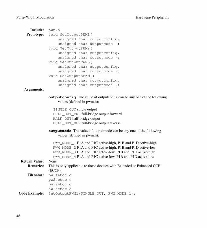
Include: pwm.hPrototype: void SetOutputPWM1(
unsigned char outputconfig,unsigned char outputmode );
void SetOutputPWM2(unsigned char outputconfig,unsigned char outputmode );
void SetOutputPWM3(unsigned char outputconfig,unsigned char outputmode );
void SetOutputEPWM1(unsigned char outputconfig,unsigned char outputmode );
Arguments:
outputconfig The value of outputconfig can be any one of the followingvalues (defined in pwm.h):
SINGLE_OUT single outputFULL_OUT_FWD full-bridge output forwardHALF_OUT half-bridge outputFULL_OUT_REV full-bridge output reverse
outputmode The value of outputmode can be any one of the followingvalues (defined in pwm.h):
PWM_MODE_1 P1A and P1C active-high, P1B and P1D active-highPWM_MODE_2 P1A and P1C active-high, P1B and P1D active-lowPWM_MODE_3 P1A and P1C active-low, P1B and P1D active-highPWM_MODE_4 P1A and P1C active-low, P1B and P1D active-low
Return Value: NoneRemarks: This is only applicable to those devices with Extended or Enhanced CCP
(ECCP).Filename: pw1setoc.c
pw2setoc.cpw3setoc.cew1setoc.c
Code Example: SetOutputPWM1(SINGLE_OUT, PWM_MODE_1);
48
Hardware Peripherals SPI
2.7 SPI
2.7.1 SPI Functions
CloseSPICloseSPI1CloseSPI2
Description: Disable the SSPx module.Include: spi.h
Prototype: void CloseSPI(void);void CloseSPI1(void);void CloseSPI2(void);
Arguments: NoneReturn Value: None
Remarks: This macro disables the SSPx module. Pin I/O returns under the control of theappropriate TRIS and LAT registers.
Filename: spi.hCode Example: CloseSPI();
DataRdySPIDataRdySPI1DataRdySPI2
Description: Determine if the SSPBUFx contains data.Include: spi.h
Prototype: unsigned char DataRdySPI(void);unsigned char DataRdySPI1(void);unsigned char DataRdySPI2(void);
Arguments: NoneReturn Value: 1 if there is data in the SSPBUFx register
0 if there is no data in the SSPBUFx registerRemarks: This function determines if there is a byte to be read from the SSPBUFx
register.Filename: spi.h
Code Example: while( ! DataRdySPI() )continue;
49
SPI Hardware Peripherals
getcSPIgetcSPI1getcSPI2See ReadSPIx.
getsSPIgetsSPI1getsSPI2
Description: Read a string from the SPIx bus.Include: spi.h
Prototype: void getsSPI(unsigned char * rdptr,unsigned char length );
void getsSPI1(unsigned char * rdptr,unsigned char length );
void getsSPI2(unsigned char * rdptr,unsigned char length );
Arguments:
rdptr Character type pointer to PICmicro MCU RAM for storage of dataread from SPI device.
length Number of bytes to read from SPIx device.
Return Value: NoneRemarks: This function reads a predefined data string length from the SPIx bus.Filename: spi_gets.c
spi1gets.cspi2gets.c
Code Example: unsigned char string[10];getsSPI(string, 10);
50

Hardware Peripherals SPI
OpenSPIOpenSPI1OpenSPI2
Description: Initialize the SSPx moduleInclude: spi.h
Prototype: void OpenSPI(unsigned char sync_mode,unsigned char bus_mode,unsigned char smp_phase );
void OpenSPI1(unsigned char sync_mode,unsigned char bus_mode,unsigned char smp_phase );
void OpenSPI2(unsigned char sync_mode,unsigned char bus_mode,unsigned char smp_phase );
Arguments:
sync_mode One of the following values, defined in spi.h:
SPI_FOSC_4 SPI Master mode, clock = FOSC/4SPI_FOSC_16 SPI Master mode, clock = FOSC/16SPI_FOSC_64 SPI Master mode, clock = FOSC/64SPI_FOSC_TMR2 SPI Master mode, clock = TMR2 output/2SLV_SSON SPI Slave mode, /SS pin control enabledSLV_SSOFF SPI Slave mode, /SS pin control disabled
bus_mode One of the following values, defined in spi.h
MODE_00 Setting for SPI bus Mode 0,0MODE_01 Setting for SPI bus Mode 0,1MODE_10 Setting for SPI bus Mode 1,0MODE_11 Setting for SPI bus Mode 1,1
continued. . .
51

SPI Hardware Peripherals
smp_phase One of the following values, defined in spi.h
SMPEND Input data sample at end of data outSMPMID Input data sample at middle of data out
Return Value: NoneRemarks: This function sets up the SSPx module for use with a SPIx bus device.Filename: spi_open.c
spi1open.cspi2open.c
Code Example: OpenSPI(SPI_FOSC_16, MODE_00, SMPEND);
putcSPIputc1SPI1putc2SPI2See WriteSPICx.
putsSPIputsSPI1putsSPI2
Description: Write a string to the SPIx bus.Include: spi.h
Prototype: void putsSPI(unsigned char * wrptr,);void putsSPI1(unsigned char * wrptr);void putsSPI2(unsigned char * wrptr);
Arguments:
wrptr Pointer to data that will be written to the SPI bus.
Return Value: NoneRemarks: This function writes out a data string to the SPIx bus device. The rou- tine is
terminated by reading a null character in the data string (the null character isnot written to the bus).
continued. . .
52

Hardware Peripherals SPI
Filename: spi_puts.cspi1puts.cspi2puts.c
Code Example: unsigned char string[] = “data to send”;putsSPI(string);
ReadSPIReadSPI1ReadSPI2getcSPIgetcSPI1getcSPI2
Description: Read a byte from the SPIx bus.Include: spi.h
Prototype: unsigned char ReadSPI(void);unsigned char ReadSPI1(void);unsigned char ReadSPI2(void);
Arguments: NoneReturn Value: The byte read during a SPIx read cycle.
Remarks: This function initiates a SPIx bus cycle for the acquisition of a byte of data.getcSPIx is defined to be ReadSPIx in spi.h.
Filename: spi_read.cspi1read.cspi2read.c
Code Example: unsigned char valuevalue = ReadSPI();
WriteSPIWriteSPI1WriteSPI2putSPIputSPI1putSPI2
continued. . .
53
SPI Hardware Peripherals
Description: Write a byte to the SPIx bus.Include: spi.h
Prototype: unsigned char WriteSPI(unsigned char data_out );
unsigned char WriteSPI1(unsigned char data_out );
unsigned char WriteSPI2(unsigned char data_out );
Arguments:
data_out A single data byte to be written to the SPIx bus device.
Return Value: 0 if the write was successful-1 if there was a write collision
Remarks: This function writes a single data byte out and then checks for a writecollision. putcSPIx is defined to be WriteSPIx in spi.h.
Filename: spi_write.cSPI1write.cSPI2write.c
Code Example: WriteSPI(’a’);
2.7.2 Example of UseThe following example demonstrates the use of an SSP module to communicate with a Microchip25C080 SPI EE memory device.
// <htc.h> will automatically include peripheral library header files when --runtime=+plib is used.#include <htc.h>// FUNCTION Prototypesvoid main(void);void set_wren(void);void busy_polling(void);unsigned char status_read(void);void status_write(unsigned char data);void byte_write(unsigned char addhigh,
unsigned char addlow,unsigned char data);
void page_write(unsigned char addhigh,unsigned char addlow,
54

Hardware Peripherals SPI
unsigned char *wrptr);void array_read(unsigned char addhigh,
unsigned char addlow,unsigned char *rdptr,unsigned char count);
unsigned char byte_read(unsigned char addhigh,unsigned char addlow);
// VARIABLE Definitionsunsigned char arraywr[] = {1,2,3,4,5,6,7,8,9,10,11,12,13,14,15,16,0};//25C040/080/160 page write sizeunsigned char arrayrd[16];unsigned char var;#define SPI_CS LATCbits.LATC2//**************************************************void main(void){
TRISCbits.TRISC2 = 0;SPI_CS = 1; // ensure SPI memory device
// Chip Select is resetOpenSPI(SPI_FOSC_16, MODE_00, SMPEND);set_wren();status_write(0);busy_polling();set_wren();byte_write(0x00, 0x61, ’E’);busy_polling();var = byte_read(0x00, 0x61);set_wren();page_write(0x00, 0x30, arraywr);busy_polling();array_read(0x00, 0x30, arrayrd, 16);var = status_read();CloseSPI();while(1);
}void set_wren(void){
SPI_CS = 0; //assert chip selectvar = putcSPI(SPI_WREN); //send write enable command
55
SPI Hardware Peripherals
SPI_CS = 1; //negate chip select}void page_write (unsigned char addhigh,
unsigned char addlow,unsigned char *wrptr)
{SPI_CS = 0; //assert chip selectvar = putcSPI(SPI_WRITE); //send write commandvar = putcSPI(addhigh); //send high byte of addressvar = putcSPI(addlow); //send low byte of addressputsSPI(wrptr); //send data byteSPI_CS = 1; //negate chip select
}void array_read (unsigned char addhigh,
unsigned char addlow,unsigned char *rdptr,unsigned char count)
{SPI_CS = 0; //assert chip selectvar = putcSPI(SPI_READ); //send read commandvar = putcSPI(addhigh); //send high byte of addressvar = putcSPI(addlow); //send low byte of addressgetsSPI(rdptr, count); //read multiple bytesSPI_CS = 1;
}void byte_write (unsigned char addhigh,
unsigned char addlow,unsigned char data)
{SPI_CS = 0; //assert chip selectvar = putcSPI(SPI_WRITE); //send write commandvar = putcSPI(addhigh); //send high byte of addressvar = putcSPI(addlow); //send low byte of addressvar = putcSPI(data); //send data byteSPI_CS = 1; //negate chip select
}unsigned char byte_read (unsigned char addhigh,
unsigned char addlow){
56

Hardware Peripherals SPI
SPI_CS = 0; //assert chip selectvar = putcSPI(SPI_READ); //send read commandvar = putcSPI(addhigh); //send high byte of addressvar = putcSPI(addlow); //send low byte of addressvar = getcSPI(); //read single byteSPI_CS = 1;return (var);
}unsigned char status_read (void){
SPI_CS = 0; //assert chip selectvar = putcSPI(SPI_RDSR); //send read status commandvar = getcSPI(); //read data byteSPI_CS = 1; //negate chip selectreturn (var);
}void status_write (unsigned char data){
SPI_CS = 0;var = putcSPI(SPI_WRSR); //write status commandvar = putcSPI(data); //status byte to writeSPI_CS = 1; //negate chip select
}void busy_polling (void){
do{
SPI_CS = 0; //assert chip selectvar = putcSPI(SPI_RDSR); //send read status commandvar = getcSPI(); //read data byteSPI_CS = 1; //negate chip select
} while (var & 0x01); //stay in loop until !busy}
57

Timer Hardware Peripherals
2.8 Timer
2.8.1 Timer Functions
CloseTimer0. . .CloseTimer4
Description: Disable the specified timer.Include: timers.h
Prototype: void CloseTimer0(void);...void CloseTimer4(void);
Arguments: NoneReturn Value: None
Remarks: This macro disables the interrupt and the specified timer.Filename: timers.h
Code Example: CloseTimer0();
OpenTimer0
Description: Configure and enable timer0.Include: timers.h
Prototype: void OpenTimer0(unsigned char config);Arguments:
config A bitmask that is created by performing a bitwise AND operation(&) with a value from each of the categories listed below. These valuesare defined in the file timers.h.
Enable Timer0 Interrupt:TIMER_INT_ON Interrupt enabledTIMER_INT_OFF Interrupt disabled
Timer Width:T0_8BIT 8-bit modeT0_16BIT 16-bit mode
Clock Source:T0_SOURCE_EXT External clock source (I/O pin)T0_SOURCE_INT Internal clock source (TOSC)
continued. . .
58
Hardware Peripherals Timer
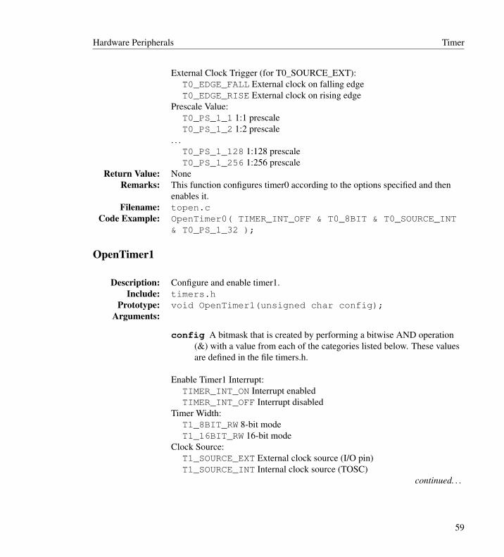
External Clock Trigger (for T0_SOURCE_EXT):T0_EDGE_FALL External clock on falling edgeT0_EDGE_RISE External clock on rising edge
Prescale Value:T0_PS_1_1 1:1 prescaleT0_PS_1_2 1:2 prescale
. . .T0_PS_1_128 1:128 prescaleT0_PS_1_256 1:256 prescale
Return Value: NoneRemarks: This function configures timer0 according to the options specified and then
enables it.Filename: topen.c
Code Example: OpenTimer0( TIMER_INT_OFF & T0_8BIT & T0_SOURCE_INT& T0_PS_1_32 );
OpenTimer1
Description: Configure and enable timer1.Include: timers.h
Prototype: void OpenTimer1(unsigned char config);Arguments:
config A bitmask that is created by performing a bitwise AND operation(&) with a value from each of the categories listed below. These valuesare defined in the file timers.h.
Enable Timer1 Interrupt:TIMER_INT_ON Interrupt enabledTIMER_INT_OFF Interrupt disabled
Timer Width:T1_8BIT_RW 8-bit modeT1_16BIT_RW 16-bit mode
Clock Source:T1_SOURCE_EXT External clock source (I/O pin)T1_SOURCE_INT Internal clock source (TOSC)
continued. . .
59

Timer Hardware Peripherals
Prescale Value:T1_PS_1_1 1:1 prescaleT1_PS_1_2 1:2 prescaleT1_PS_1_4 1:4 prescaleT1_PS_1_8 1:8 prescale
Oscillator Use:T1_OSC1EN_ON Enable Timer1 oscillatorT1_OSC1EN_OFF Disable Timer1 oscillator
Synchronize Clock Input:T1_SYNC_EXT_ON Sync external clock inputT1_SYNC_EXT_OFF Don’t sync external clock input
Use With CCP:(For devices with 1 or 2 CCPs)
T3_SOURCE_CCP Timer3 source for both CCP’sT1_CCP1_T3_CCP2 Timer1 source for CCP1 and Timer3 source for
CCP2T1_SOURCE_CCP Timer1 source for both CCP’s
(For devices with more than 2 CCPs)T34_SOURCE_CCP Timer3 and Timer4 are sources for all CCP’sT12_CCP12_T34_CCP345 Timer1 and Timer2 are sources for CCP1
and CCP2 and Timer3 and Timer4 are sources for CCP3 through CCP5T12_CCP1_T34_CCP2345 Timer1 and Timer2 are sources for CCP1
and Timer3 and Timer4 are sources for CCP2 through CCP5T12_SOURCE_CCP Timer1 and Timer2 are sources for all CCP’s
Return Value: NoneRemarks: This function configures timer1 according to the options specified and then
enables it.Filename: topen.c
Code Example: OpenTimer1(T1_SOURCE_EXT & T1_PS_1_1 & T1_OSC1EN_OFF& T1_SYNC_EXT_OFF );
OpenTimer2
Description: Configure and enable timer1.Include: timers.h
Prototype: void OpenTimer2(unsigned char config);continued. . .
60

Hardware Peripherals Timer
Arguments:
config A bitmask that is created by performing a bitwise AND operation(&) with a value from each of the categories listed below. These valuesare defined in the file timers.h.
Enable Timer2 Interrupt:TIMER_INT_ON Interrupt enabledTIMER_INT_OFF Interrupt disabled
Prescale Value:T2_PS_1_1 1:1 prescaleT2_PS_1_4 1:4 prescaleT2_PS_1_16 1:16 prescale
Postscale Value:T2_POST_1_1 1:1 prescaleT2_POST_1_2 1:2 prescale
...T2_POST_1_15 1:15 prescaleT2_POST_1_16 1:16 prescale
Use With CCP:(For devices with 1 or 2 CCPs)
T3_SOURCE_CCP Timer3 source for both CCP’sT1_CCP1_T3_CCP2 Timer1 source for CCP1 and Timer3 source for
CCP2T1_SOURCE_CCP Timer1 source for both CCP’s
(For devices with more than 2 CCPs)T34_SOURCE_CCP Timer3 and Timer4 are sources for all CCP’sT12_CCP12_T34_CCP345 Timer1 and Timer2 are sources for CCP1
and CCP2 and Timer3 and Timer4 are sources for CCP3 through CCP5T12_CCP1_T34_CCP2345 Timer1 and Timer2 are sources for CCP1
and Timer3 and Timer4 are sources for CCP2 through CCP5T12_SOURCE_CCP Timer1 and Timer2 are sources for all CCP’s
Return Value: NoneRemarks: This function configures timer1 according to the options specified and then
enables it.Filename: topen.c
Code Example: OpenTimer2(TIMER_INT_OFF & T2_PS_1_1 & T2_POST_1_8);
61
Timer Hardware Peripherals
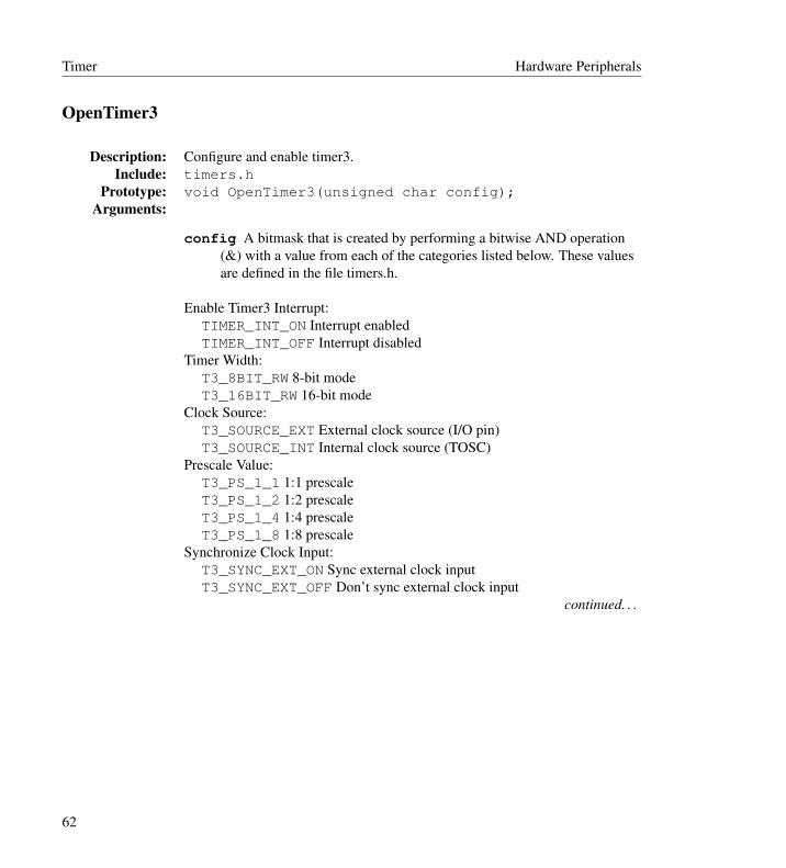
OpenTimer3
Description: Configure and enable timer3.Include: timers.h
Prototype: void OpenTimer3(unsigned char config);Arguments:
config A bitmask that is created by performing a bitwise AND operation(&) with a value from each of the categories listed below. These valuesare defined in the file timers.h.
Enable Timer3 Interrupt:TIMER_INT_ON Interrupt enabledTIMER_INT_OFF Interrupt disabled
Timer Width:T3_8BIT_RW 8-bit modeT3_16BIT_RW 16-bit mode
Clock Source:T3_SOURCE_EXT External clock source (I/O pin)T3_SOURCE_INT Internal clock source (TOSC)
Prescale Value:T3_PS_1_1 1:1 prescaleT3_PS_1_2 1:2 prescaleT3_PS_1_4 1:4 prescaleT3_PS_1_8 1:8 prescale
Synchronize Clock Input:T3_SYNC_EXT_ON Sync external clock inputT3_SYNC_EXT_OFF Don’t sync external clock input
continued. . .
62

Hardware Peripherals Timer
Use With CCP:(For devices with 1 or 2 CCPs)
T3_SOURCE_CCP Timer3 source for both CCP’sT1_CCP1_T3_CCP2 Timer1 source for CCP1 and Timer3 source for
CCP2T1_SOURCE_CCP Timer1 source for both CCP’s
(For devices with more than 2 CCPs)T34_SOURCE_CCP Timer3 and Timer4 are sources for all CCP’sT12_CCP12_T34_CCP345 Timer1 and Timer2 are sources for CCP1
and CCP2 and Timer3 and Timer4 are sources for CCP3 through CCP5T12_CCP1_T34_CCP2345 Timer1 and Timer2 are sources for CCP1
and Timer3 and Timer4 are sources for CCP2 through CCP5T12_SOURCE_CCP Timer1 and Timer2 are sources for all CCP’s
Return Value: NoneRemarks: This function configures timer1 according to the options specified and then
enables it.Filename: topen.c
Code Example: OpenTimer3(TIMER_INT_ON & T3_8BIT_RW & T3_SOURCE_EXT& T3_PS_1_1 & T3_OSC1EN_OFF & T3_SYNC_EXT_OFF );
OpenTimer4
Description: Configure and enable timer4.Include: timers.h
Prototype: void OpenTimer4(unsigned char config);Arguments:
config A bitmask that is created by performing a bitwise AND operation(&) with a value from each of the categories listed below. These valuesare defined in the file timers.h.
Enable Timer4 Interrupt:TIMER_INT_ON Interrupt enabledTIMER_INT_OFF Interrupt disabled
Prescale Value:T4_PS_1_1 1:1 prescaleT4_PS_1_4 1:4 prescaleT4_PS_1_16 1:16 prescale
continued. . .
63

Timer Hardware Peripherals
Postscale Value:T4_POST_1_1 1:1 prescaleT4_POST_1_2 1:2 prescale
...T4_POST_1_15 1:15 prescaleT4_POST_1_16 1:16 prescale
Return Value: NoneRemarks: This function configures timer4 according to the options specified and then
enables it.Filename: topen.c
Code Example: OpenTimer2(TIMER_INT_OFF & T4_PS_1_1 & T4_POST_1_8);
ReadTimer0. . .ReadTimer4
Description: Read the value of the specified timer.Include: timers.h
Prototype: unsigned int ReadTimer0(void);unsigned int ReadTimer1(void);unsigned char ReadTimer2(void);unsigned int ReadTimer3(void);unsigned char ReadTimer4(void);
Arguments: NoneReturn Value: The current value of the timer.
Remarks: These routines read the value of the respective timer register(s).Timer0: TMR0L,TMR0HTimer1: TMR1L,TMR1HTimer2: TMR2Timer3: TMR3L,TMR3HTimer4: TMR4
Note: When using a timer in 8-bit mode that may be configured in 16-bitmode (e.g., timer0), the upper byte is not ensured to be zero. The user maywish to cast the result to a char for correct results.
Filename: tread.ctimers.h
continued. . .
64
Hardware Peripherals Timer
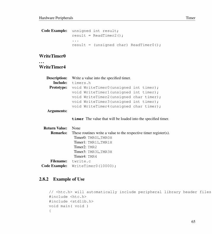
Code Example: unsigned int result;result = ReadTimer2();...result = (unsigned char) ReadTimer0();
WriteTimer0. . .WriteTimer4
Description: Write a value into the specified timer.Include: timers.h
Prototype: void WriteTimer0(unsigned int timer);void WriteTimer1(unsigned int timer);void WriteTimer2(unsigned char timer);void WriteTimer3(unsigned int timer);void WriteTimer4(unsigned char timer);
Arguments:
timer The value that will be loaded into the specified timer.
Return Value: NoneRemarks: These routines write a value to the respective timer register(s).
Timer0: TMR0L,TMR0HTimer1: TMR1L,TMR1HTimer2: TMR2Timer3: TMR3L,TMR3HTimer4: TMR4
Filename: twrite.cCode Example: WriteTimer0(10000);
2.8.2 Example of Use
// <htc.h> will automatically include peripheral library header files when --runtime=+plib is used.#include <htc.h>#include <stdlib.h>void main( void ){
65
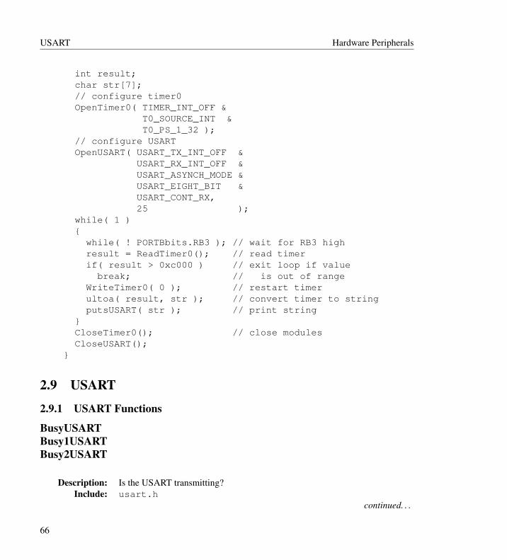
USART Hardware Peripherals
int result;char str[7];// configure timer0OpenTimer0( TIMER_INT_OFF &
T0_SOURCE_INT &T0_PS_1_32 );
// configure USARTOpenUSART( USART_TX_INT_OFF &
USART_RX_INT_OFF &USART_ASYNCH_MODE &USART_EIGHT_BIT &USART_CONT_RX,25 );
while( 1 ){
while( ! PORTBbits.RB3 ); // wait for RB3 highresult = ReadTimer0(); // read timerif( result > 0xc000 ) // exit loop if value
break; // is out of rangeWriteTimer0( 0 ); // restart timerultoa( result, str ); // convert timer to stringputsUSART( str ); // print string
}CloseTimer0(); // close modulesCloseUSART();
}
2.9 USART
2.9.1 USART Functions
BusyUSARTBusy1USARTBusy2USART
Description: Is the USART transmitting?Include: usart.h
continued. . .
66

Hardware Peripherals USART
Prototype: char BusyUSART(void);char Busy1USART(void);char Busy2USART(void);
Arguments: NoneReturn Value: 0 if the USART transmitter is idle
1 if the USART transmitter is in useRemarks: Returns a value indicating if the USART transmitter is currently busy. This
function should be used prior to commencing a new transmission.BusyUSART should be used on parts with a single USART peripheral.Busy1USART and Busy2USART should be used on parts with multipleUSART peripherals.
Filename: usart.hCode Example: while(BusyUSART())
continue;
CloseUSARTClose1USARTClose2USART
Description: Disable the specified USART.Include: usart.h
Prototype: void CloseUSART(void);void Close1USART(void);void Close2USART(void);
Arguments: NoneReturn Value: None
Remarks: This macro disables the interrupts, transmitter and receiver for the specifiedUSART. CloseUSART should be used on parts with a single USARTperipheral. Close1USART and Close2USART should be used on parts withmultiple USART peripherals.
Filename: usart.hCode Example: CloseUSART();
DataRdyUSARTDataRdy1USARTDataRdy2USART
67

USART Hardware Peripherals
Description: Is data available in the USART read buffer?Include: usart.h
Prototype: char DataRdyUSART(void);char DataRdy1USART(void);char DataRdy2USART(void);
Arguments: NoneReturn Value: 1 if data is available
0 if data is not availableRemarks: This macro returns the status of the RCIF flag bit in the PIR register.
DataRdyUSART should be used on parts with a single USART peripheral.DataRdy1USART and DataRdy2USART should be used on parts withmultiple USART peripherals.
Filename: usart.hCode Example: while( ! DataRdyUSART() )
continue;
getcUSARTgetc1USARTgetc2USARTSee ReadUSART.
getsUSARTgets1USARTgets2USART
Description: Read a fixed-length string of characters from the specified USART.Include: usart.h
Prototype: void getsUSART(unsigned char * buffer,unsigned char length );
void gets1USART(unsigned char * buffer,unsigned char length );
void gets2USART(unsigned char * buffer,unsigned char length );
continued. . .
68

Hardware Peripherals USART
Arguments:
buffer A pointer to the location where incoming characters are to bestored.
length Number of bytes to read from the USART.
Return Value: NoneRemarks: This function only works in 8-bit transmit/receive mode. This function waits
for and reads len number of characters out of the specified USART. There isno time out when waiting for characters to arrive. getsUSART should be usedon parts with a single USART peripheral. gets1USART and gets2USARTshould be used on parts with multiple USART peripherals.
Filename: ugets.cCode Example: char string[10];
getsUSART(string, 5);
OpenUSARTOpen1USARTOpen2USART
Description: Configure the specified USART module.Include: usart.h
Prototype: void OpenUSART(unsigned char config,unsigned char spbrg);
void Open1USART(unsigned char config,unsigned char spbrg);
void Open2USART(unsigned char config,unsigned char spbrg);
Arguments:
config A bitmask that is created by performing a bitwise AND operation(&) with a value from each of the categories listed below. These valuesare defined in the file usart.h.
continued. . .
69
USART Hardware Peripherals
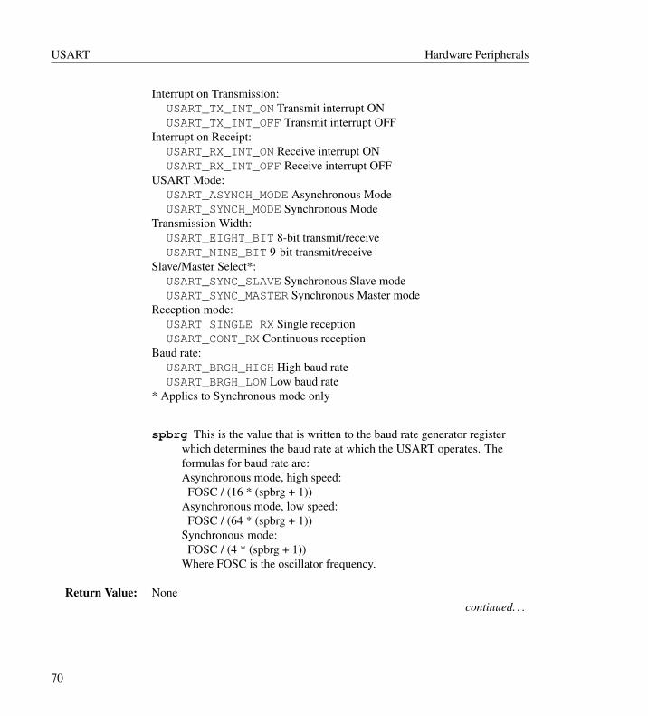
Interrupt on Transmission:USART_TX_INT_ON Transmit interrupt ONUSART_TX_INT_OFF Transmit interrupt OFF
Interrupt on Receipt:USART_RX_INT_ON Receive interrupt ONUSART_RX_INT_OFF Receive interrupt OFF
USART Mode:USART_ASYNCH_MODE Asynchronous ModeUSART_SYNCH_MODE Synchronous Mode
Transmission Width:USART_EIGHT_BIT 8-bit transmit/receiveUSART_NINE_BIT 9-bit transmit/receive
Slave/Master Select*:USART_SYNC_SLAVE Synchronous Slave modeUSART_SYNC_MASTER Synchronous Master mode
Reception mode:USART_SINGLE_RX Single receptionUSART_CONT_RX Continuous reception
Baud rate:USART_BRGH_HIGH High baud rateUSART_BRGH_LOW Low baud rate
* Applies to Synchronous mode only
spbrg This is the value that is written to the baud rate generator registerwhich determines the baud rate at which the USART operates. Theformulas for baud rate are:Asynchronous mode, high speed:
FOSC / (16 * (spbrg + 1))Asynchronous mode, low speed:
FOSC / (64 * (spbrg + 1))Synchronous mode:
FOSC / (4 * (spbrg + 1))Where FOSC is the oscillator frequency.
Return Value: Nonecontinued. . .
70
Hardware Peripherals USART
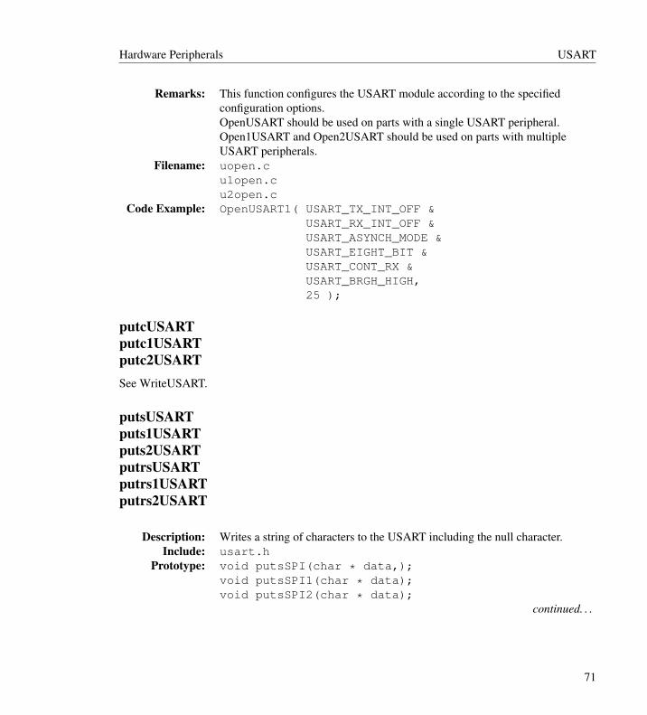
Remarks: This function configures the USART module according to the specifiedconfiguration options.OpenUSART should be used on parts with a single USART peripheral.Open1USART and Open2USART should be used on parts with multipleUSART peripherals.
Filename: uopen.cu1open.cu2open.c
Code Example: OpenUSART1( USART_TX_INT_OFF &USART_RX_INT_OFF &USART_ASYNCH_MODE &USART_EIGHT_BIT &USART_CONT_RX &USART_BRGH_HIGH,25 );
putcUSARTputc1USARTputc2USARTSee WriteUSART.
putsUSARTputs1USARTputs2USARTputrsUSARTputrs1USARTputrs2USART
Description: Writes a string of characters to the USART including the null character.Include: usart.h
Prototype: void putsSPI(char * data,);void putsSPI1(char * data);void putsSPI2(char * data);
continued. . .
71

USART Hardware Peripherals
Arguments:
data Pointer to a nul-terminated string of data.
Return Value: NoneRemarks: This function only works in 8-bit transmit/receive mode. This function writes
a string of data to the USART including the null character. These funtionswould with any character strings regardless of their storage location.putsUSART should be used on parts with a single USART peripheral. Theother functions should be used on parts with multiple USART peripherals.
Filename: uputs.cCode Example: putsUSART(“Hello World”);
ReadUSARTRead1USARTRead2USARTgetcUSARTgetc1USARTget2USART
Description: Read a byte (one character) out of the USART receive buffer, including the9th bit if enabled.
Include: usart.hPrototype: char ReadUSART(void);
char Read1USART(void);char Read2USART(void);char getcUSART(void);char getc1USART(void);char getc2USART(void);
Arguments: NoneReturn Value: This function returns the next character in the USART receive buffer.
continued. . .
72

Hardware Peripherals USART
Remarks: This function reads a byte out of the USART receive buffer. The Status bitsand the 9th data bits are saved in a union with the following declaration:union USART {
unsigned char val;struct {
unsigned RX_NINE:1;unsigned TX_NINE:1;unsigned FRAME_ERROR:1;unsigned OVERRUN_ERROR:1;unsigned fill:4;
};};The 9th bit is read-only if 9-bit mode is enabled. The Status bits are alwaysread.On a part with a single USART peripheral, the getcUSART and ReadUSARTfunctions should be used and the status information is read into a variablenamed USART_Status which is of the type USART described above.On a part with multiple USART peripherals, the getcxUSART andReadxUSART functions should be used and the status information is read intoa variable named USARTx_Status which is of the type USART describedabove.
Filename: uread.cCode Example: int result;
result = ReadUSART();result |= (unsigned int) USART_Status.RX_NINE << 8;
WriteUSARTWrite1USARTWrite2USARTputUSARTput1USARTput2USART
Description: Write a byte (one character) to the USART transmit buffer, including the 9thbit if enabled.
Include: usart.hcontinued. . .
73

USART Hardware Peripherals
Prototype: unsigned char WriteUSART(char data );
unsigned char Write1USART(char data );
unsigned char Write2USART(char data );
unsigned char putcUSART(char data );
unsigned char putc1USART(char data );
unsigned char putc2USART(char data );
Arguments:
data The value to be written to the USART.
Return Value: NoneRemarks: This function writes a byte to the USART transmit buffer. If 9-bit mode is
enabled, the 9th bit is written from the field TX_NINE, found in a variable oftype USART:union USART {
unsigned char val;struct {
unsigned RX_NINE:1;unsigned TX_NINE:1;unsigned FRAME_ERROR:1;unsigned OVERRUN_ERROR:1;unsigned fill:4;
};};On a part with a single USART peripheral, the putcUSART and WriteUSARTfunctions should be used and the Status register is named USART_Statuswhich is of the type USART described above.On a part with multiple USART peripherals, the putcxUSART andWritexUSART functions should be used and the status register is namedUSARTx_Status which is of the type USART described above.
Filename: uwrite.cu1write.cu2write.c
continued. . .
74
Hardware Peripherals USART
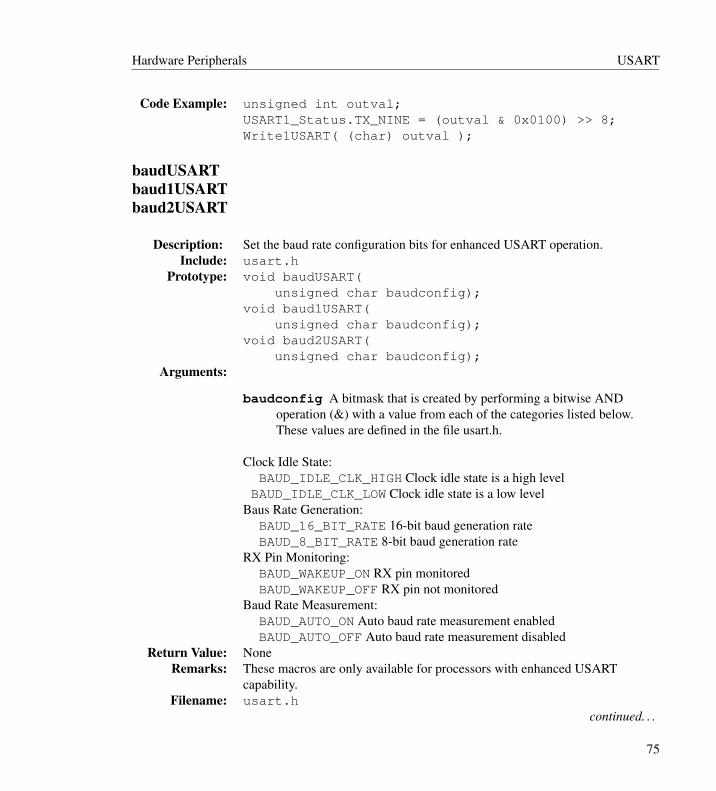
Code Example: unsigned int outval;USART1_Status.TX_NINE = (outval & 0x0100) >> 8;Write1USART( (char) outval );
baudUSARTbaud1USARTbaud2USART
Description: Set the baud rate configuration bits for enhanced USART operation.Include: usart.h
Prototype: void baudUSART(unsigned char baudconfig);
void baud1USART(unsigned char baudconfig);
void baud2USART(unsigned char baudconfig);
Arguments:
baudconfig A bitmask that is created by performing a bitwise ANDoperation (&) with a value from each of the categories listed below.These values are defined in the file usart.h.
Clock Idle State:BAUD_IDLE_CLK_HIGH Clock idle state is a high level
BAUD_IDLE_CLK_LOW Clock idle state is a low levelBaus Rate Generation:
BAUD_16_BIT_RATE 16-bit baud generation rateBAUD_8_BIT_RATE 8-bit baud generation rate
RX Pin Monitoring:BAUD_WAKEUP_ON RX pin monitoredBAUD_WAKEUP_OFF RX pin not monitored
Baud Rate Measurement:BAUD_AUTO_ON Auto baud rate measurement enabledBAUD_AUTO_OFF Auto baud rate measurement disabled
Return Value: NoneRemarks: These macros are only available for processors with enhanced USART
capability.Filename: usart.h
continued. . .
75
USART Hardware Peripherals
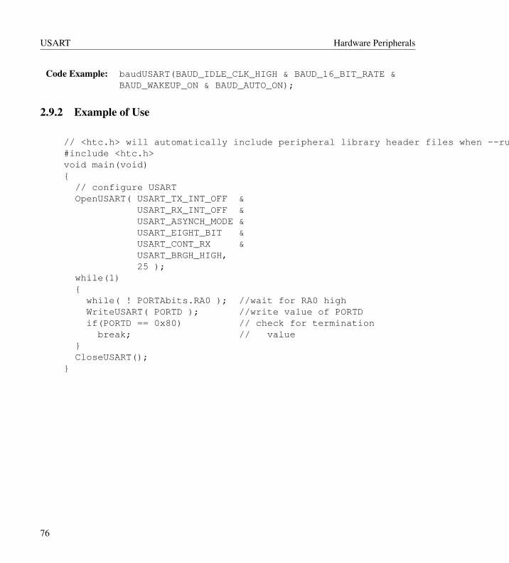
Code Example: baudUSART(BAUD_IDLE_CLK_HIGH & BAUD_16_BIT_RATE &BAUD_WAKEUP_ON & BAUD_AUTO_ON);
2.9.2 Example of Use
// <htc.h> will automatically include peripheral library header files when --runtime=+plib is used.#include <htc.h>void main(void){
// configure USARTOpenUSART( USART_TX_INT_OFF &
USART_RX_INT_OFF &USART_ASYNCH_MODE &USART_EIGHT_BIT &USART_CONT_RX &USART_BRGH_HIGH,25 );
while(1){
while( ! PORTAbits.RA0 ); //wait for RA0 highWriteUSART( PORTD ); //write value of PORTDif(PORTD == 0x80) // check for termination
break; // value}CloseUSART();
}
76
Chapter 3
Software Peripherals
3.1 LCD
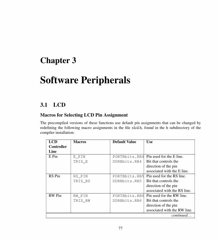
Macros for Selecting LCD Pin AssignmentThe precompiled versions of these functions use default pin assignments that can be changed byredefining the following macro assignments in the file xlcd.h, found in the h subdirectory of thecompiler installation:
LCDControllerLine
Macros Default Value Use
E Pin E_PINTRIS_E
PORTBbits.RB4DDRBbits.RB4
Pin used for the E line.Bit that controls thedirection of the pinassociated with the E line.
RS Pin RS_PINTRIS_RS
PORTBbits.RB5DDRBbits.RB5
Pin used for the RS line.Bit that controls thedirection of the pinassociated with the RS line.
RW Pin RW_PINTRIS_RW
PORTBbits.RB6DDRBbits.RB6
Pin used for the RW line.Bit that controls thedirection of the pinassociated with the RW line.
continued. . .
77
LCD Software Peripherals
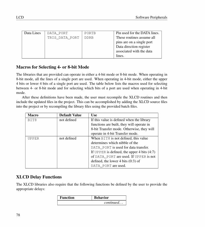
Data Lines DATA_PORTTRIS_DATA_PORT
PORTBDDRB
Pin used for the DATA lines.These routines assume allpins are on a single portData direction registerassociated with the datalines.
Macros for Selecting 4- or 8-bit ModeThe libraries that are provided can operate in either a 4-bit mode or 8-bit mode. When operating in8-bit mode, all the lines of a single port are used. When operating in 4-bit mode, either the upper4 bits or lower 4 bits of a single port are used. The table below lists the macros used for selectingbetween 4- or 8-bit mode and for selecting which bits of a port are used when operating in 4-bitmode.
After these definitions have been made, the user must recompile the XLCD routines and theninclude the updated files in the project. This can be accomplished by adding the XLCD source filesinto the project or by recompiling the library files using the provided batch files.
Macro Default Value UseBIT8 not defined If this value is defined when the library
functions are built, they will operate in8-bit Transfer mode. Otherwise, they willoperate in 4-bit Transfer mode.
UPPER not defined When BIT8 is not defined, this valuedetermines which nibble of theDATA_PORT is used for data transfer.If UPPER is defined, the upper 4 bits (4:7)of DATA_PORT are used. If UPPER is notdefined, the lower 4 bits (0:3) ofDATA_PORT are used.
XLCD Delay FunctionsThe XLCD libraries also require that the following functions be defined by the user to provide theappropriate delays:
Function Behaviorcontinued. . .
78
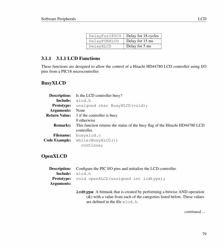
Software Peripherals LCD
DelayFor18TCY Delay for 18 cyclesDelayPORXLCD Delay for 15 msDelayXLCD Delay for 5 ms
3.1.1 3.1.1 LCD FunctionsThese functions are designed to allow the control of a Hitachi HD44780 LCD controller using I/Opins from a PIC18 microcontroller.
BusyXLCD
Description: Is the LCD controller busy?Include: xlcd.h
Prototype: unsigned char BusyXLCD(void);Arguments: None
Return Value: 1 if the controller is busy0 otherwise
Remarks: This function returns the status of the busy flag of the Hitachi HD44780 LCDcontroller.
Filename: busyxlcd.cCode Example: while(BusyXLCD())
continue;
OpenXLCD
Description: Configure the PIC I/O pins and initialize the LCD controller.Include: xlcd.h
Prototype: void openXLCD(unsigned int lcdtype);Arguments:
lcdtype A bitmask that is created by performing a bitwise AND operation(&) with a value from each of the categories listed below. These valuesare defined in the file xlcd.h.
continued. . .
79
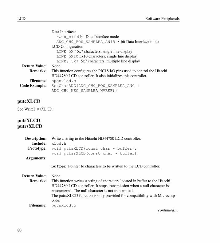
LCD Software Peripherals
Data Interface:FOUR_BIT 4-bit Data Interface modeADC_CH0_POS_SAMPLEA_AN15 8-bit Data Interface mode
LCD ConfigurationLINE_5X7 5x7 characters, single line displayLINE_5X10 5x10 characters, single line displayLINES_5X7 5x7 characters, multiple line display
Return Value: NoneRemarks: This function configures the PIC18 I/O pins used to control the Hitachi
HD44780 LCD controller. It also initializes this controller.Filename: openxlcd.c
Code Example: SetChanADC(ADC_CH0_POS_SAMPLEA_AN0 |ADC_CH0_NEG_SAMPLEA_NVREF);
putcXLCDSee WriteDataXLCD.
putsXLCDputrsXLCD
Description: Write a string to the Hitachi HD44780 LCD controller.Include: xlcd.h
Prototype: void putsXLCD(const char * buffer);void putsrXLCD(const char * buffer);
Arguments:
buffer Pointer to characters to be written to the LCD controller.
Return Value: NoneRemarks: This function writes a string of characters located in buffer to the Hitachi
HD44780 LCD controller. It stops transmission when a null character isencountered. The null character is not transmitted.The putrsXLCD function is only provided for compatibility with Microchipcode.
Filename: putsxlcd.ccontinued. . .
80
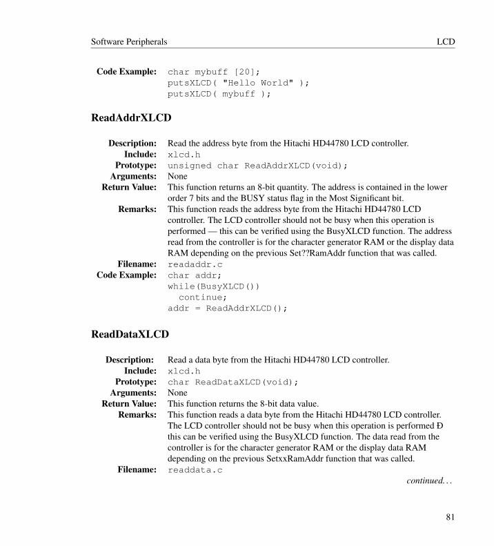
Software Peripherals LCD
Code Example: char mybuff [20];putsXLCD( "Hello World" );putsXLCD( mybuff );
ReadAddrXLCD
Description: Read the address byte from the Hitachi HD44780 LCD controller.Include: xlcd.h
Prototype: unsigned char ReadAddrXLCD(void);Arguments: None
Return Value: This function returns an 8-bit quantity. The address is contained in the lowerorder 7 bits and the BUSY status flag in the Most Significant bit.
Remarks: This function reads the address byte from the Hitachi HD44780 LCDcontroller. The LCD controller should not be busy when this operation isperformed — this can be verified using the BusyXLCD function. The addressread from the controller is for the character generator RAM or the display dataRAM depending on the previous Set??RamAddr function that was called.
Filename: readaddr.cCode Example: char addr;
while(BusyXLCD())continue;
addr = ReadAddrXLCD();
ReadDataXLCD
Description: Read a data byte from the Hitachi HD44780 LCD controller.Include: xlcd.h
Prototype: char ReadDataXLCD(void);Arguments: None
Return Value: This function returns the 8-bit data value.Remarks: This function reads a data byte from the Hitachi HD44780 LCD controller.
The LCD controller should not be busy when this operation is performed Ðthis can be verified using the BusyXLCD function. The data read from thecontroller is for the character generator RAM or the display data RAMdepending on the previous SetxxRamAddr function that was called.
Filename: readdata.ccontinued. . .
81
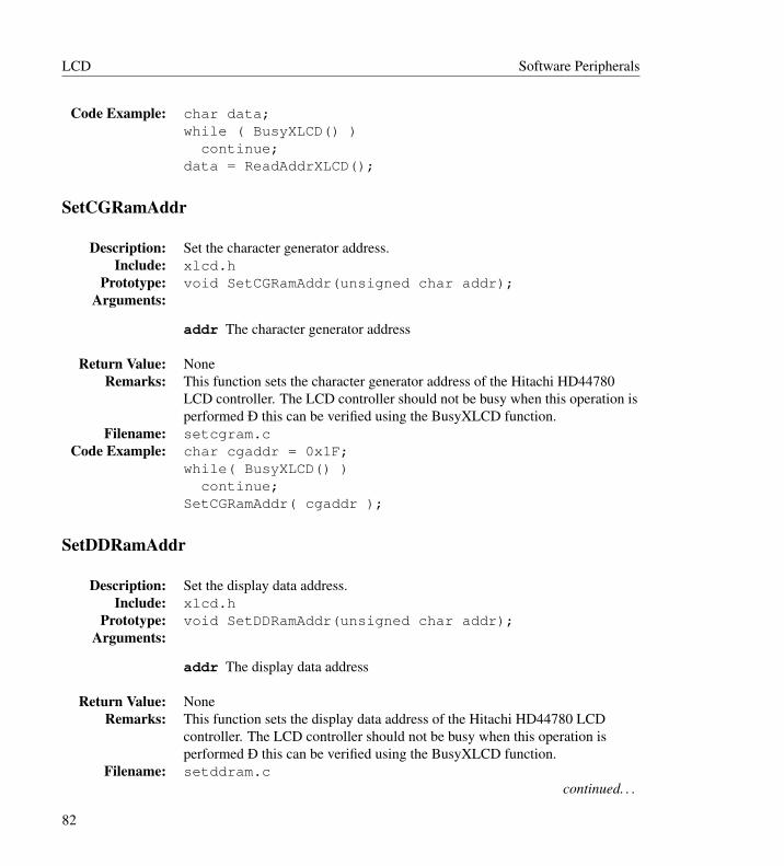
LCD Software Peripherals
Code Example: char data;while ( BusyXLCD() )
continue;data = ReadAddrXLCD();
SetCGRamAddr
Description: Set the character generator address.Include: xlcd.h
Prototype: void SetCGRamAddr(unsigned char addr);Arguments:
addr The character generator address
Return Value: NoneRemarks: This function sets the character generator address of the Hitachi HD44780
LCD controller. The LCD controller should not be busy when this operation isperformed Ð this can be verified using the BusyXLCD function.
Filename: setcgram.cCode Example: char cgaddr = 0x1F;
while( BusyXLCD() )continue;
SetCGRamAddr( cgaddr );
SetDDRamAddr
Description: Set the display data address.Include: xlcd.h
Prototype: void SetDDRamAddr(unsigned char addr);Arguments:
addr The display data address
Return Value: NoneRemarks: This function sets the display data address of the Hitachi HD44780 LCD
controller. The LCD controller should not be busy when this operation isperformed Ð this can be verified using the BusyXLCD function.
Filename: setddram.ccontinued. . .
82

Software Peripherals LCD
Code Example: char ddaddr = 0x1F;while( BusyXLCD() )
continue;SetDDRamAddr( ddaddr );
WriteCmdXLCD
Description: Write a command to the Hitachi HD44780 LCD controller.Include: xlcd.h
Prototype: void openXLCD(unsigned char cmd);Arguments: cmd Specifies the command to be performed. The command may be one of
the following values defined in xlcd.h:DOFF Turn display offCURSOR_OFF Enable display with no cursorBLINK_ON Enable display with blinking cursorBLINK_OFF Enable display with unblinking cursor
SHIFT_CUR_LEFT Cursor shifts to the leftSHIFT_CUR_RIGHT Cursor shifts to the rightSHIFT_DISP_LEFT Display shifts to the leftSHIFT_DISP_RIGHT Display shifts to the right
Alternatively, the command may be a bitmask that is created by performing abitwise AND operation (&) with a value from each of the categories listedbelow. These values are defined in the file xlcd.h.Data Transfer Mode:
FOUR_BIT 4-bit Data Interface modeEIGHT_BIT 8-bit Data Interface mode
Display TypeLINE_5X7 5x7 characters, single line displayLINE_5X10 5x10 characters, single line displayLINES_5X7 5x7 characters, multiple line display
Return Value: NoneRemarks: This function writes the command byte to the Hitachi HD44780 LCD
controller. The LCD controller should not be busy when this operation isperformed Ð this can be verified using the BusyXLCD function.
Filename: wcmdxlcd.ccontinued. . .
83

LCD Software Peripherals
Code Example: while( BusyXLCD() )continue;
WriteCmdXLCD( EIGHT_BIT & LINES_5X7 );WriteCmdXLCD( BLINK_ON );WriteCmdXLCD( SHIFT_DISP_LEFT );
putcXLCDWriteDataXLCD
Description: Writes a byte to the Hitachi HD44780 LCD controller.Include: xlcd.h
Prototype: void WriteDataXLCD(char data);Arguments:
data The value of data can be any 8-bit value, but should correspond to thecharacter RAM table of the HD44780 LCD controller.
Return Value: NoneRemarks: This function writes a data byte to the Hitachi HD44780 LCD controller. The
LCD controller should not be busy when this operation is performed — thiscan be verified using the BusyXLCD function. The data read from thecontroller is for the character generator RAM or the display data RAMdepending on the previous SetxxRamAddr function that was called.
Filename: writdata.cCode Example: WriteDataXLCD(0x10);
3.1.2 Example of Use
// <htc.h> will automatically include peripheral library header files when --runtime=+plib is used.#include <htc.h>void DelayFor18TCY( void ){
Nop();Nop();Nop();Nop();Nop();
84

Software Peripherals LCD
Nop();Nop();Nop();Nop();Nop();Nop();Nop();
}void DelayPORXLCD (void){
Delay1KTCYx(60); // Delay of 15ms// Cycles = (TimeDelay * Fosc) / 4// Cycles = (15ms * 16MHz) / 4// Cycles = 60,000
return;}void DelayXLCD (void){
Delay1KTCYx(20); // Delay of 5ms// Cycles = (TimeDelay * Fosc) / 4// Cycles = (5ms * 16MHz) / 4// Cycles = 20,000
return;}void main( void ){
char data;// configure external LCDOpenXLCD( EIGHT_BIT & LINES_5X7 );// configure USARTOpenUSART( USART_TX_INT_OFF & USART_RX_INT_OFF &
USART_ASYNCH_MODE & USART_EIGHT_BIT &USART_CONT_RX,25);
while(1){
while(!DataRdyUSART()); //wait for datadata = ReadUSART(); //read dataWriteDataXLCD(data); //write to LCD
85

CAN Software Peripherals
if(data==’Q’)break;
}CloseUSART();
}
3.2 CAN
3.2.1 CAN FunctionsThis section documents the MCP2510 external peripheral library functions.
CAN2510BitModify
Description: Modifies the specified bits in a register to the new values.Req’d Modes: All
Include: can2510.hPrototype: void CAN2510BitModify(
unsigned char addr,unsigned char mask,unsigned char data );
Arguments:
addr The value of addr specifies the address of the MCP2510 register tomodify.
mask The value of mask specifies the bits that will be modified.
data The value of data specifies the new state of the bits.
Return Value: NoneRemarks: This function modifies the contents of the register specified by address, the
mask specifies which bits are to be modified and the data specifies the newvalue to load into those bits. Only specific registers can be modified with theBit Modify command.
Filename: canbmod.cCode Example:
86
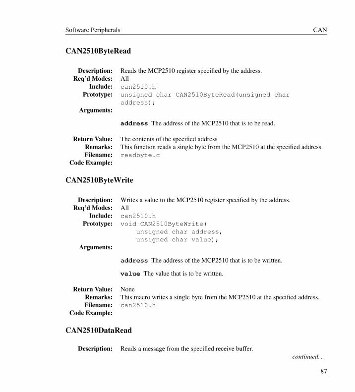
Software Peripherals CAN
CAN2510ByteRead
Description: Reads the MCP2510 register specified by the address.Req’d Modes: All
Include: can2510.hPrototype: unsigned char CAN2510ByteRead(unsigned char
address);Arguments:
address The address of the MCP2510 that is to be read.
Return Value: The contents of the specified addressRemarks: This function reads a single byte from the MCP2510 at the specified address.Filename: readbyte.c
Code Example:
CAN2510ByteWrite
Description: Writes a value to the MCP2510 register specified by the address.Req’d Modes: All
Include: can2510.hPrototype: void CAN2510ByteWrite(
unsigned char address,unsigned char value);
Arguments:
address The address of the MCP2510 that is to be written.
value The value that is to be written.
Return Value: NoneRemarks: This macro writes a single byte from the MCP2510 at the specified address.Filename: can2510.h
Code Example:
CAN2510DataRead
Description: Reads a message from the specified receive buffer.continued. . .
87
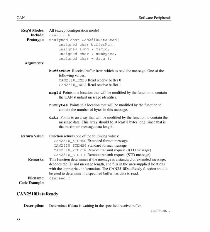
CAN Software Peripherals
Req’d Modes: All (except configuration mode)Include: can2510.h
Prototype: unsigned char CAN2510DataRead(unsigned char bufferNum,unsigned long * msgId,unsigned char * numBytes,unsigned char * data );
Arguments:
bufferNum Receive buffer from which to read the message. One of thefollowing values:CAN2510_RXB0 Read receive buffer 0CAN2510_RXB1 Read receive buffer 1
msgId Points to a location that will be modified by the function to containthe CAN standard message identifier.
numBytes Points to a location that will be modified by the function tocontain the number of bytes in this message.
data Points to an array that will be modified by the function to contain themessage data. This array should be at least 8 bytes long, since that isthe maximum message data length.
Return Value: Function returns one of the following values:CAN2510_XTDMSG Extended format messageCAN2510_STDMSG Standard format messageCAN2510_XTDRTR Remote transmit request (XTD message)CAN2510_STDRTR Remote transmit request (STD message)
Remarks: This function determines if the message is a standard or extended message,decodes the ID and message length, and fills in the user-supplied locationswith the appropriate information. The CAN2510DataReady function shouldbe used to determine if a specified buffer has data to read.
Filename: canread.cCode Example:
CAN2510DataReady
Description: Determines if data is waiting in the specified receive buffer.continued. . .
88
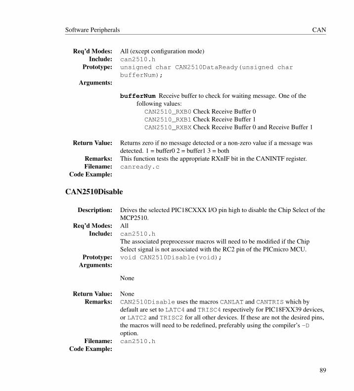
Software Peripherals CAN
Req’d Modes: All (except configuration mode)Include: can2510.h
Prototype: unsigned char CAN2510DataReady(unsigned charbufferNum);
Arguments:
bufferNum Receive buffer to check for waiting message. One of thefollowing values:
CAN2510_RXB0 Check Receive Buffer 0CAN2510_RXB1 Check Receive Buffer 1CAN2510_RXBX Check Receive Buffer 0 and Receive Buffer 1
Return Value: Returns zero if no message detected or a non-zero value if a message wasdetected. 1 = buffer0 2 = buffer1 3 = both
Remarks: This function tests the appropriate RXnIF bit in the CANINTF register.Filename: canready.c
Code Example:
CAN2510Disable
Description: Drives the selected PIC18CXXX I/O pin high to disable the Chip Select of theMCP2510.
Req’d Modes: AllInclude: can2510.h
The associated preprocessor macros will need to be modified if the ChipSelect signal is not associated with the RC2 pin of the PICmicro MCU.
Prototype: void CAN2510Disable(void);Arguments:
None
Return Value: NoneRemarks: CAN2510Disable uses the macros CANLAT and CANTRIS which by
default are set to LATC4 and TRISC4 respectively for PIC18FXX39 devices,or LATC2 and TRISC2 for all other devices. If these are not the desired pins,the macros will need to be redefined, preferably using the compiler’s -Doption.
Filename: can2510.hCode Example:
89
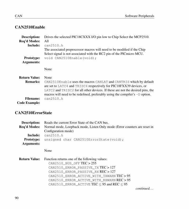
CAN Software Peripherals
CAN2510Enable
Description: Drives the selected PIC18CXXX I/O pin low to Chip Select the MCP2510.Req’d Modes: All
Include: can2510.hThe associated preprocessor macros will need to be modified if the ChipSelect signal is not associated with the RC2 pin of the PICmicro MCU.
Prototype: void CAN2510Enable(void);Arguments:
None
Return Value: NoneRemarks: CAN2510Enable uses the macros CANLAT and CANTRIS which by default
are set to LATC4 and TRISC4 respectively for PIC18FXX39 devices, orLATC2 and TRISC2 for all other devices. If these are not the desired pins, themacros will need to be redefined, preferably using the compiler’s -D option.
Filename: can2510.hCode Example:
CAN2510ErrorState
Description: Reads the current Error State of the CAN bus.Req’d Modes: Normal mode, Loopback mode, Listen Only mode (Error counters are reset in
Configuration mode)Include: can2510.h
Prototype: unsigned char CAN2510ErrorState(void);Arguments:
None
Return Value: Function returns one of the following values:CAN2510_BUS_OFF TEC > 255CAN2510_ERROR_PASSIVE_TX TEC > 127CAN2510_ERROR_PASSIVE_RX REC > 127CAN2510_ERROR_ACTIVE_WITH_TXWARN TEC > 95CAN2510_ERROR_ACTIVE_WITH_RXWARN REC > 95CAN2510_ERROR_ACTIVE TEC ≤ 95 and REC ≤ 95
continued. . .
90

Software Peripherals CAN
Remarks: This function returns the Error State of the CAN bus. The Error State isdependent on the values in the TEC and REC registers.
Filename: canerrst.cCode Example:
CAN2510Init
Description: Initialize the PIC18CXXX SPI port for communications to the MCP2510 andthen configures the MCP2510 registers to interface with the CAN bus
Req’d Modes: Configuration modeInclude: can2510.h
Prototype: unsigned char CAN2510Init(unsigned short long BufferConfig,unsigned short long BitTimeConfig,unsigned char interruptEnables,unsigned char SPI_syncMode,unsigned char SPI_busMode,unsigned char SPI_smpPhase );
Arguments:
BufferConfig The value of BufferConfig is constructed through thebitwise AND (&) operation of the following options. Only one optionper group function may be selected. The option in the bold font is thedefault value.
Reset MCP2510 DeviceSpecifies if the MCP2510 Reset command is to be sent. This does notcorrespond to a bit in the MCP2510 registers.
CAN2510_NORESET Don’t reset the MCP2510CAN2510_RESET Reset the MCP2510
Buffer 0 FilteringControlled by the RXB0M1:RXB0M0 bits (RXB0CTRL register)
CAN2510_RXB0_USEFILT Receive all messages, Use filtersCAN2510_RXB0_STDMSG Receive only Standard messagesCAN2510_RXB0_XTDMSG Receive only Extended messagesCAN2510_RXB0_NOFILT Receive all messages, NO filters
continued. . .continued. . .
91

CAN Software Peripherals
Buffer 1 FilteringControlled by the RXB1M1:RXB1M0 bits (RXB1CTRL register)
CAN2510_RXB1_USEFILT Receive all messages, Use filtersCAN2510_RXB1_STDMSG Receive only Standard messagesCAN2510_RXB1_XTDMSG Receive only Extended messagesCAN2510_RXB1_NOFILT Receive all messages, NO filters
Receive Buffer 0 to Receive Buffer 1 RolloverControlled by the BUKT bit (RXB0CTRL register)
CAN2510_RXB0_ROLL If receive buffer 0 is full, message goes toreceive buffer 1
CAN2510_RXB0_NOROLL Rollover DisabledRX1BF Pin SettingControlled by the B1BFS:B1BFE:B1BFM bits (BFPCTRL register)
CAN2510_RX1BF_OFF RX1BF pin is high-impedanceCAN2510_RX1BF_INT RX1BF pin is an output which indicates
Receive Buffer 1 was loaded. Can be used as an interrupt signal.CAN2510_RX1BF_GPOUTH RX1BF pin is a general purpose digital
output, Output HighCAN2510_RX1BF_GPOUTL RX1BF pin is a general purpose digital
output, Output LowRX0BF Pin SettingControlled by the B0BFS:B0BFE:B0BFM bits (BFPCTRL register)
CAN2510_RX0BF_OFF RX0BF pin is high-impedanceCAN2510_RX0BF_INT RX0BF pin is an output which indicates
Receive Buffer 0 was loaded. Can be used as an interrupt signal.CAN2510_RX0BF_GPOUTH RX0BF pin is a general purpose digital
output, Output HighCAN2510_RX0BF_GPOUTL RX0BF pin is a general purpose digital
output, Output LowTX2 Pin SettingControlled by the B2RTSM bit (TXRTSCTRL register)
CAN2510_TX2_GPIN TX2RTS pin is a digital inputCAN2510_TX2_RTS TX2RTS pin is an input used to initiate a Request
To Send frame from TXBUF2continued. . .continued. . .
92
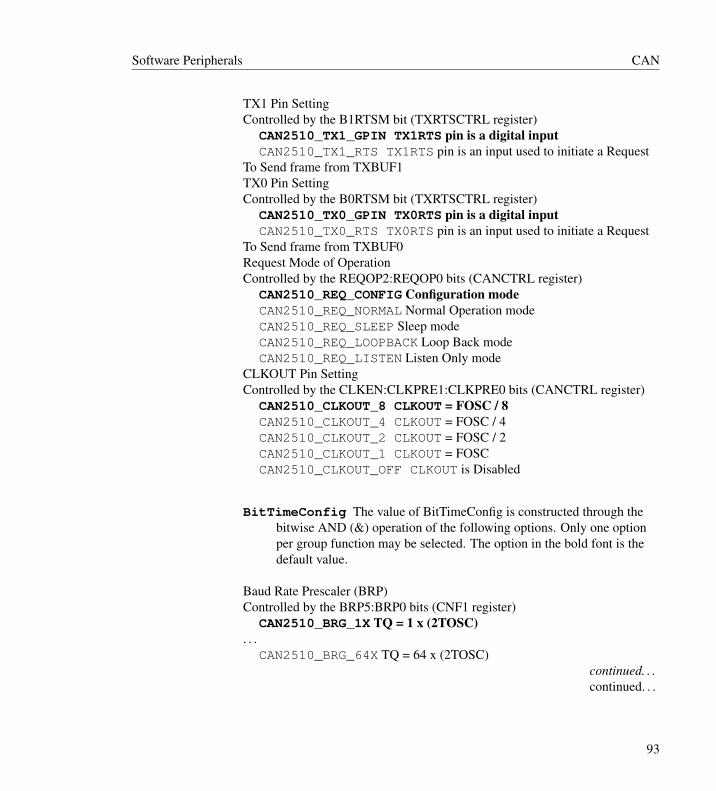
Software Peripherals CAN
TX1 Pin SettingControlled by the B1RTSM bit (TXRTSCTRL register)
CAN2510_TX1_GPIN TX1RTS pin is a digital inputCAN2510_TX1_RTS TX1RTS pin is an input used to initiate a Request
To Send frame from TXBUF1TX0 Pin SettingControlled by the B0RTSM bit (TXRTSCTRL register)
CAN2510_TX0_GPIN TX0RTS pin is a digital inputCAN2510_TX0_RTS TX0RTS pin is an input used to initiate a Request
To Send frame from TXBUF0Request Mode of OperationControlled by the REQOP2:REQOP0 bits (CANCTRL register)
CAN2510_REQ_CONFIG Configuration modeCAN2510_REQ_NORMAL Normal Operation modeCAN2510_REQ_SLEEP Sleep modeCAN2510_REQ_LOOPBACK Loop Back modeCAN2510_REQ_LISTEN Listen Only mode
CLKOUT Pin SettingControlled by the CLKEN:CLKPRE1:CLKPRE0 bits (CANCTRL register)
CAN2510_CLKOUT_8 CLKOUT = FOSC / 8CAN2510_CLKOUT_4 CLKOUT = FOSC / 4CAN2510_CLKOUT_2 CLKOUT = FOSC / 2CAN2510_CLKOUT_1 CLKOUT = FOSCCAN2510_CLKOUT_OFF CLKOUT is Disabled
BitTimeConfig The value of BitTimeConfig is constructed through thebitwise AND (&) operation of the following options. Only one optionper group function may be selected. The option in the bold font is thedefault value.
Baud Rate Prescaler (BRP)Controlled by the BRP5:BRP0 bits (CNF1 register)
CAN2510_BRG_1X TQ = 1 x (2TOSC). . .
CAN2510_BRG_64X TQ = 64 x (2TOSC)continued. . .continued. . .
93
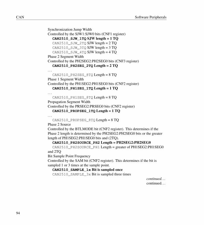
CAN Software Peripherals
Synchronization Jump WidthControlled by the SJW1:SJW0 bits (CNF1 register)
CAN2510_SJW_1TQ SJW length = 1 TQCAN2510_SJW_2TQ SJW length = 2 TQCAN2510_SJW_3TQ SJW length = 3 TQCAN2510_SJW_4TQ SJW length = 4 TQ
Phase 2 Segment WidthControlled by the PH2SEG2:PH2SEG0 bits (CNF3 register)
CAN2510_PH2SEG_2TQ Length = 2 TQ. . .
CAN2510_PH2SEG_8TQ Length = 8 TQPhase 1 Segment WidthControlled by the PH1SEG2:PH1SEG0 bits (CNF2 register)
CAN2510_PH1SEG_1TQ Length = 1 TQ. . .
CAN2510_PH1SEG_8TQ Length = 8 TQPropagation Segment WidthControlled by the PRSEG2:PRSEG0 bits (CNF2 register)
CAN2510_PROPSEG_1TQ Length = 1 TQ. . .
CAN2510_PROPSEG_8TQ Length = 8 TQPhase 2 SourceControlled by the BTLMODE bit (CNF2 register). This determines if thePhase 2 length is determined by the PH2SEG2:PH2SEG0 bits or the greaterlength of PH1SEG2:PH1SEG0 bits and (2TQ).
CAN2510_PH2SOURCE_PH2 Length = PH2SEG2:PH2SEG0CAN2510_PH2SOURCE_PH1 Length = greater of PH1SEG2:PH1SEG0
and 2TQBit Sample Point FrequencyControlled by the SAM bit (CNF2 register). This determines if the bit issampled 1 or 3 times at the sample point.
CAN2510_SAMPLE_1x Bit is sampled onceCAN2510_SAMPLE_3x Bit is sampled three times
continued. . .continued. . .
94
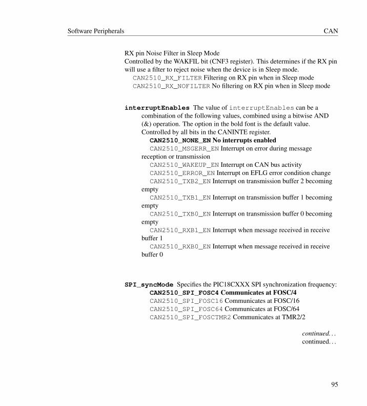
Software Peripherals CAN
RX pin Noise Filter in Sleep ModeControlled by the WAKFIL bit (CNF3 register). This determines if the RX pinwill use a filter to reject noise when the device is in Sleep mode.
CAN2510_RX_FILTER Filtering on RX pin when in Sleep modeCAN2510_RX_NOFILTER No filtering on RX pin when in Sleep mode
interruptEnables The value of interruptEnables can be acombination of the following values, combined using a bitwise AND(&) operation. The option in the bold font is the default value.Controlled by all bits in the CANINTE register.
CAN2510_NONE_EN No interrupts enabledCAN2510_MSGERR_EN Interrupt on error during message
reception or transmissionCAN2510_WAKEUP_EN Interrupt on CAN bus activityCAN2510_ERROR_EN Interrupt on EFLG error condition changeCAN2510_TXB2_EN Interrupt on transmission buffer 2 becoming
emptyCAN2510_TXB1_EN Interrupt on transmission buffer 1 becoming
emptyCAN2510_TXB0_EN Interrupt on transmission buffer 0 becoming
emptyCAN2510_RXB1_EN Interrupt when message received in receive
buffer 1CAN2510_RXB0_EN Interrupt when message received in receive
buffer 0
SPI_syncMode Specifies the PIC18CXXX SPI synchronization frequency:CAN2510_SPI_FOSC4 Communicates at FOSC/4CAN2510_SPI_FOSC16 Communicates at FOSC/16CAN2510_SPI_FOSC64 Communicates at FOSC/64CAN2510_SPI_FOSCTMR2 Communicates at TMR2/2
continued. . .continued. . .
95
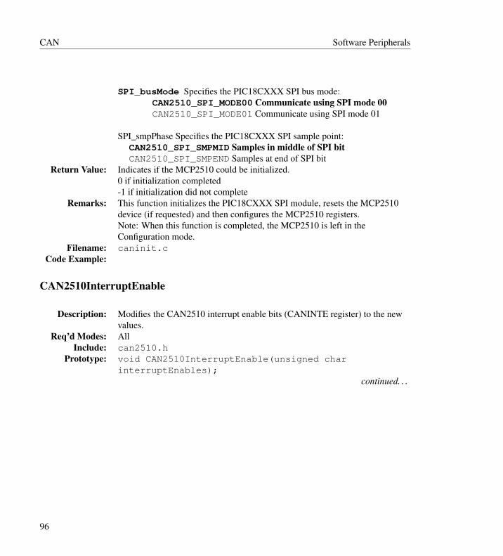
CAN Software Peripherals
SPI_busMode Specifies the PIC18CXXX SPI bus mode:CAN2510_SPI_MODE00 Communicate using SPI mode 00CAN2510_SPI_MODE01 Communicate using SPI mode 01
SPI_smpPhase Specifies the PIC18CXXX SPI sample point:CAN2510_SPI_SMPMID Samples in middle of SPI bitCAN2510_SPI_SMPEND Samples at end of SPI bit
Return Value: Indicates if the MCP2510 could be initialized.0 if initialization completed-1 if initialization did not complete
Remarks: This function initializes the PIC18CXXX SPI module, resets the MCP2510device (if requested) and then configures the MCP2510 registers.Note: When this function is completed, the MCP2510 is left in theConfiguration mode.
Filename: caninit.cCode Example:
CAN2510InterruptEnable
Description: Modifies the CAN2510 interrupt enable bits (CANINTE register) to the newvalues.
Req’d Modes: AllInclude: can2510.h
Prototype: void CAN2510InterruptEnable(unsigned charinterruptEnables);
continued. . .
96

Software Peripherals CAN
Arguments:
interruptEnables The value of interruptEnables can be a combinationof the following values, combined using a bitwise AND (&) operation.The option in the bold font is the default value. Controlled by all bits inthe CANINTE register.
CAN2510_NONE_EN No interrupts enabled (00000000)CAN2510_MSGERR_EN Interrupt on error during message
reception or transmission (10000000)CAN2510_WAKEUP_EN Interrupt on CAN bus activity (01000000)CAN2510_ERROR_EN Interrupt on EFLG error condition change
(00100000)CAN2510_TXB2_EN Interrupt on transmission buffer 2 becoming
empty (00010000)CAN2510_TXB1_EN Interrupt on transmission buffer 1 becoming
empty (00001000)CAN2510_TXB0_EN Interrupt on transmission buffer 0 becoming
empty (00000100)CAN2510_RXB1_EN Interrupt when message received in receive
buffer 1 (00000010)CAN2510_RXB0_EN Interrupt when message received in receive
buffer 0 (00000001)
Return Value: NoneRemarks: This macro updates the CANINTE register with the value that is determined
by ANDing the desired interrupt sources.Filename: can2510.h
Code Example:
CAN2510InterruptStatus
Description: Indicates the source of the CAN2510 interrupt.Req’d Modes: All
Include: can2510.hPrototype: unsigned char CAN2510InterruptStatus(void);
Arguments:
None
continued. . .
97
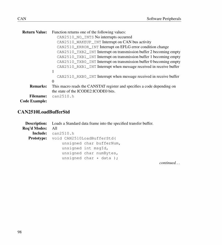
CAN Software Peripherals
Return Value: Function returns one of the following values:CAN2510_NO_INTS No interrupts occurredCAN2510_WAKEUP_INT Interrupt on CAN bus activityCAN2510_ERROR_INT Interrupt on EFLG error condition changeCAN2510_TXB2_INT Interrupt on transmission buffer 2 becoming emptyCAN2510_TXB1_INT Interrupt on transmission buffer 1 becoming emptyCAN2510_TXB0_INT Interrupt on transmission buffer 0 becoming emptyCAN2510_RXB1_INT Interrupt when message received in receive buffer
1CAN2510_RXB0_INT Interrupt when message received in receive buffer
0Remarks: This macro reads the CANSTAT register and specifies a code depending on
the state of the ICODE2:ICODE0 bits.Filename: can2510.h
Code Example:
CAN2510LoadBufferStd
Description: Loads a Standard data frame into the specified transfer buffer.Req’d Modes: All
Include: can2510.hPrototype: void CAN2510LoadBufferStd(
unsigned char bufferNum,unsigned int msgId,unsigned char numBytes,unsigned char * data );
continued. . .
98
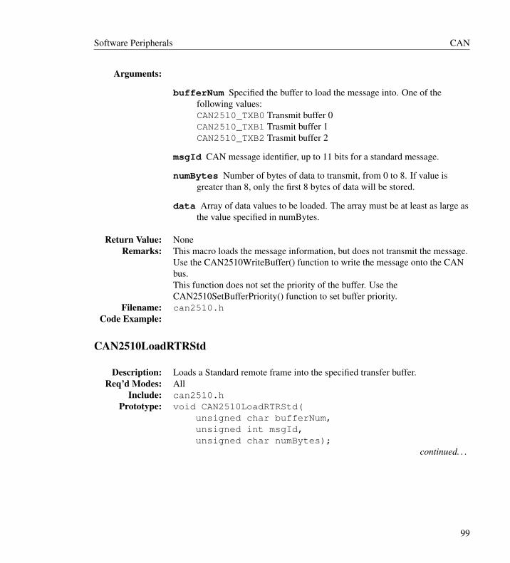
Software Peripherals CAN
Arguments:
bufferNum Specified the buffer to load the message into. One of thefollowing values:CAN2510_TXB0 Transmit buffer 0CAN2510_TXB1 Trasmit buffer 1CAN2510_TXB2 Trasmit buffer 2
msgId CAN message identifier, up to 11 bits for a standard message.
numBytes Number of bytes of data to transmit, from 0 to 8. If value isgreater than 8, only the first 8 bytes of data will be stored.
data Array of data values to be loaded. The array must be at least as large asthe value specified in numBytes.
Return Value: NoneRemarks: This macro loads the message information, but does not transmit the message.
Use the CAN2510WriteBuffer() function to write the message onto the CANbus.This function does not set the priority of the buffer. Use theCAN2510SetBufferPriority() function to set buffer priority.
Filename: can2510.hCode Example:
CAN2510LoadRTRStd
Description: Loads a Standard remote frame into the specified transfer buffer.Req’d Modes: All
Include: can2510.hPrototype: void CAN2510LoadRTRStd(
unsigned char bufferNum,unsigned int msgId,unsigned char numBytes);
continued. . .
99

CAN Software Peripherals
Arguments:
bufferNum Specified the buffer to load the message into. One of thefollowing values:CAN2510_TXB0 Transmit buffer 0CAN2510_TXB1 Trasmit buffer 1CAN2510_TXB2 Trasmit buffer 2
msgId CAN message identifier, up to 11 bits for a standard message.
numBytes Number of bytes of data to transmit, from 0 to 8. If value isgreater than 8, only the first 8 bytes of data will be stored.
Return Value: NoneRemarks: This function loads the message information, but does not transmit the
message. Use the CAN2510WriteBuffer() function to write the messageonto the CAN bus.This function does not set the priority of the buffer. Use theCAN2510SetBufferPriority() function to set buffer priority.
Filename: canlrtrs.cCode Example:
CAN2510LoadRTRXtd
Description: Loads a Extended remote frame into the specified transfer buffer.Req’d Modes: All
Include: can2510.hPrototype: void CAN2510LoadRTRXtd(
unsigned char bufferNum,unsigned long msgId,unsigned char numBytes);
continued. . .
100

Software Peripherals CAN
Arguments:
bufferNum Specified the buffer to load the message into. One of thefollowing values:CAN2510_TXB0 Transmit buffer 0CAN2510_TXB1 Trasmit buffer 1CAN2510_TXB2 Trasmit buffer 2
msgId CAN message identifier, up to 29 bits for an extended message.
numBytes Number of bytes of data to transmit, from 0 to 8. If value isgreater than 8, only the first 8 bytes of data will be stored.
Return Value: NoneRemarks: This function loads the message information, but does not transmit the
message. Use the CAN2510WriteBuffer() function to write the messageonto the CAN bus.This function does not set the priority of the buffer. Use theCAN2510SetBufferPriority() function to set buffer priority.
Filename: canlrtrx.cCode Example:
CAN2510ReadMode
Description: Reads the MCP2510 current mode of operation.Req’d Modes: All
Include: can2510.hPrototype: unsigned char CAN2510ReadMode(void);
Arguments:
None
Return Value: The return value can be one of the following values (defined in can2510.h).Specified by the OPMODE2:OPMODE0 bits (CANSTAT register).
CAN2510_MODE_CONFIG Configuration registers can be modifiedCAN2510_MODE_NORMAL Normal (send and receive messages)CAN2510_MODE_SLEEP Wait for interruptCAN2510_MODE_LISTEN Listen only, don’t sendCAN2510_MODE_LOOPBACK Used for testing, messages stay internal
continued. . .
101
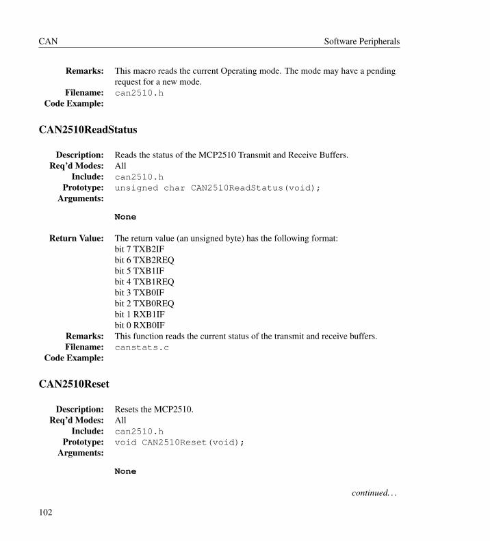
CAN Software Peripherals
Remarks: This macro reads the current Operating mode. The mode may have a pendingrequest for a new mode.
Filename: can2510.hCode Example:
CAN2510ReadStatus
Description: Reads the status of the MCP2510 Transmit and Receive Buffers.Req’d Modes: All
Include: can2510.hPrototype: unsigned char CAN2510ReadStatus(void);
Arguments:
None
Return Value: The return value (an unsigned byte) has the following format:bit 7 TXB2IFbit 6 TXB2REQbit 5 TXB1IFbit 4 TXB1REQbit 3 TXB0IFbit 2 TXB0REQbit 1 RXB1IFbit 0 RXB0IF
Remarks: This function reads the current status of the transmit and receive buffers.Filename: canstats.c
Code Example:
CAN2510Reset
Description: Resets the MCP2510.Req’d Modes: All
Include: can2510.hPrototype: void CAN2510Reset(void);
Arguments:
None
continued. . .
102

Software Peripherals CAN
Return Value: NoneRemarks: This macro resets the MCP2510.Filename: can2510.h
Code Example:
CAN2510SendBuffer
Description: Requests message transmission for the specified transmit buffer(s).Req’d Modes: Normal
Include: can2510.hPrototype: void CAN2510SendBuffer(unsigned char bufferNum);
Arguments:
bufferNum Specified the trasmit buffer. One of the following values:CAN2510_TXB0 Transmit buffer 0CAN2510_TXB1 Trasmit buffer 1CAN2510_TXB2 Trasmit buffer 2CAN2510_TXB20_B1 Trasmit buffer 0 and buffer 1CAN2510_TXB20_B2 Trasmit buffer 0 and buffer 2CAN2510_TXB21_B2 Trasmit buffer 1 and buffer 2CAN2510_TXB21_B1_B2 Trasmit buffer 0, buffer 1 and buffer 2
Return Value: NoneRemarks: This function requests transmission of a previously loaded message stored in
the specified buffer(s). To load a message, use theCAN2510LoadBufferStd() or CAN2510LoadBufferXtd()routines.
Filename: cansend.cCode Example:
CAN2510SequentialRead
Description: Reads the number of specified bytes in the MCP2510, starting at the specifiedaddress. These values will be stored in DataArray.
Req’d Modes: AllInclude: can2510.h
continued. . .
103

CAN Software Peripherals
Prototype: void CAN2510SequentialRead(unsigned char * DataArray,unsigned char CAN2510addr,unsigned char numBytes);
Arguments:
DataArray The start address of the data array that stores the sequentialread data.
CAN2510addr The address of the MCP2510 where the sequential readsstart from.
numBytes The number of bytes to sequentialy read.
Return Value: NoneRemarks: This function reads sequential bytes from the MCP2510 starting at the
specified address. These values are loaded starting at the first address of thearray that is specified.
Filename: readseq.cCode Example:
CAN2510SequentialWrite
Description: Writes the number of specified bytes in the MCP2510, starting at the specifiedaddress. These values will be written from DataArray.
Req’d Modes: AllInclude: can2510.h
Prototype: void CAN2510SequentialRead(unsigned char * DataArray,unsigned char CAN2510addr,unsigned char numBytes);
continued. . .
104
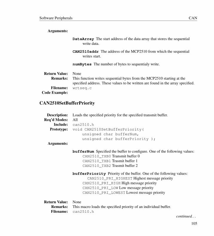
Software Peripherals CAN
Arguments:
DataArray The start address of the data array that stores the sequentialwrite data.
CAN2510addr The address of the MCP2510 from which the sequentialwrites start.
numBytes The number of bytes to sequentialy write.
Return Value: NoneRemarks: This function writes sequential bytes from the MCP2510 starting at the
specified address. These values to be written are found in the array specified.Filename: wrtseq.c
Code Example:
CAN2510SetBufferPriority
Description: Loads the specified priority for the specified transmit buffer.Req’d Modes: All
Include: can2510.hPrototype: void CAN2510SetBufferPriority(
unsigned char bufferNum,unsigned char bufferPriority );
Arguments:
bufferNum Specified the buffer to configure. One of the following values:CAN2510_TXB0 Transmit buffer 0CAN2510_TXB1 Trasmit buffer 1CAN2510_TXB2 Trasmit buffer 2
bufferPriority Priority of the buffer. One of the following values:CAN2510_PRI_HIGHEST Highest message priority
CAN2510_PRI_HIGH High message priorityCAN2510_PRI_LOW Low message priorityCAN2510_PRI_LOWEST Lowest message priority
Return Value: NoneRemarks: This macro loads the specified priority of an individual buffer.Filename: can2510.h
continued. . .
105
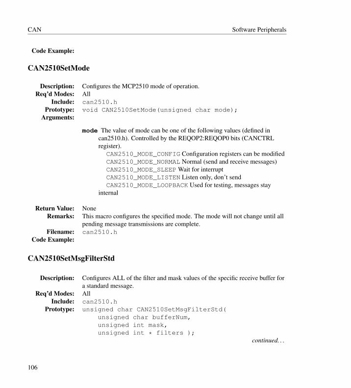
CAN Software Peripherals
Code Example:
CAN2510SetMode
Description: Configures the MCP2510 mode of operation.Req’d Modes: All
Include: can2510.hPrototype: void CAN2510SetMode(unsigned char mode);
Arguments:
mode The value of mode can be one of the following values (defined incan2510.h). Controlled by the REQOP2:REQOP0 bits (CANCTRLregister).
CAN2510_MODE_CONFIG Configuration registers can be modifiedCAN2510_MODE_NORMAL Normal (send and receive messages)CAN2510_MODE_SLEEP Wait for interruptCAN2510_MODE_LISTEN Listen only, don’t sendCAN2510_MODE_LOOPBACK Used for testing, messages stay
internal
Return Value: NoneRemarks: This macro configures the specified mode. The mode will not change until all
pending message transmissions are complete.Filename: can2510.h
Code Example:
CAN2510SetMsgFilterStd
Description: Configures ALL of the filter and mask values of the specific receive buffer fora standard message.
Req’d Modes: AllInclude: can2510.h
Prototype: unsigned char CAN2510SetMsgFilterStd(unsigned char bufferNum,unsigned int mask,unsigned int * filters );
continued. . .
106

Software Peripherals CAN
Arguments:
bufferNum Specified the buffer to configure. One of the following values:CAN2510_RXB0 Configure RXM0, RXF0 and RXF1CAN2510_RXB1 Configure RXM1, RXF2, RXF3, RXF4 and RXF
mask Value to store in the corresponding mask
filters Array of filter values.For Buffer 0 Standard-length messages:
Array of 2 unsigned integersFor Buffer 1
Standard-length messages: Array of 4 unsigned integers
Return Value: Indicates if the MCP2510 modes could be modified properly.0 if initialization and restoration of Operating mode completed-1 if initialization and restoration of Operating mode did not complete
Remarks: This function configures the MCP2510 into Configuration mode, then writesthe mask and filter values out to the appropriate registers. Before returning, itconfigures the MCP2510 to the original mode.
Filename: canfms.cCode Example:
CAN2510SetMsgFilterXtd
Description: Configures ALL of the filter and mask values of the specific receive buffer foran extended message.
Req’d Modes: AllInclude: can2510.h
Prototype: unsigned char CAN2510SetMsgFilterXtd(unsigned char bufferNum,unsigned long mask,unsigned long * filters );
continued. . .
107

CAN Software Peripherals
Arguments:
bufferNum Specified the buffer to configure. One of the following values:CAN2510_RXB0 Configure RXM0, RXF0 and RXF1CAN2510_RXB1 Configure RXM1, RXF2, RXF3, RXF4 and RXF
mask Value to store in the corresponding mask
filters Array of filter values.For Buffer 0 Extended-length messages:
Array of 2 unsigned long integersFor Buffer 1
Standard-length messages: Array of 4 unsigned long integers
Return Value: Indicates if the MCP2510 modes could be modified properly.0 if initialization and restoration of Operating mode completed-1 if initialization and restoration of Operating mode did not complete
Remarks: This function configures the MCP2510 into Configuration mode, then writesthe mask and filter values out to the appropriate registers. Before returning, itconfigures the MCP2510 to the original mode.
Filename: canfmx.cCode Example:
CAN2510SetSingleFilterStd
Description: Configures the specified Receive filter with a filter value for a Standard (Std)message.
Req’d Modes: ConfigurationInclude: can2510.h
Prototype: unsigned char CAN2510SetSingleFilterStd(unsign
ed char filterNum,unsigned int filter);
continued. . .
108
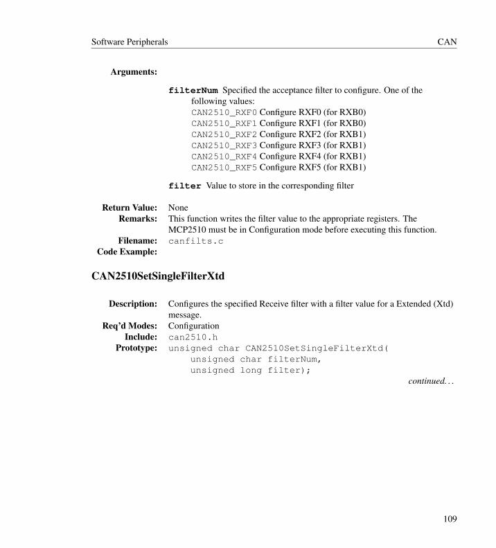
Software Peripherals CAN
Arguments:
filterNum Specified the acceptance filter to configure. One of thefollowing values:CAN2510_RXF0 Configure RXF0 (for RXB0)CAN2510_RXF1 Configure RXF1 (for RXB0)CAN2510_RXF2 Configure RXF2 (for RXB1)CAN2510_RXF3 Configure RXF3 (for RXB1)CAN2510_RXF4 Configure RXF4 (for RXB1)CAN2510_RXF5 Configure RXF5 (for RXB1)
filter Value to store in the corresponding filter
Return Value: NoneRemarks: This function writes the filter value to the appropriate registers. The
MCP2510 must be in Configuration mode before executing this function.Filename: canfilts.c
Code Example:
CAN2510SetSingleFilterXtd
Description: Configures the specified Receive filter with a filter value for a Extended (Xtd)message.
Req’d Modes: ConfigurationInclude: can2510.h
Prototype: unsigned char CAN2510SetSingleFilterXtd(unsigned char filterNum,unsigned long filter);
continued. . .
109
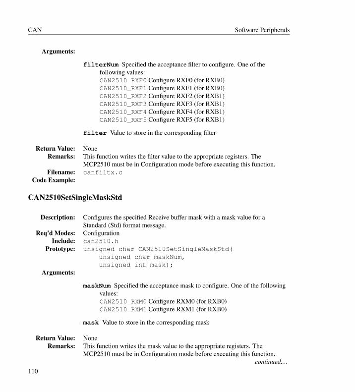
CAN Software Peripherals
Arguments:
filterNum Specified the acceptance filter to configure. One of thefollowing values:CAN2510_RXF0 Configure RXF0 (for RXB0)CAN2510_RXF1 Configure RXF1 (for RXB0)CAN2510_RXF2 Configure RXF2 (for RXB1)CAN2510_RXF3 Configure RXF3 (for RXB1)CAN2510_RXF4 Configure RXF4 (for RXB1)CAN2510_RXF5 Configure RXF5 (for RXB1)
filter Value to store in the corresponding filter
Return Value: NoneRemarks: This function writes the filter value to the appropriate registers. The
MCP2510 must be in Configuration mode before executing this function.Filename: canfiltx.c
Code Example:
CAN2510SetSingleMaskStd
Description: Configures the specified Receive buffer mask with a mask value for aStandard (Std) format message.
Req’d Modes: ConfigurationInclude: can2510.h
Prototype: unsigned char CAN2510SetSingleMaskStd(unsigned char maskNum,unsigned int mask);
Arguments:
maskNum Specified the acceptance mask to configure. One of the followingvalues:CAN2510_RXM0 Configure RXM0 (for RXB0)CAN2510_RXM1 Configure RXM1 (for RXB0)
mask Value to store in the corresponding mask
Return Value: NoneRemarks: This function writes the mask value to the appropriate registers. The
MCP2510 must be in Configuration mode before executing this function.continued. . .
110
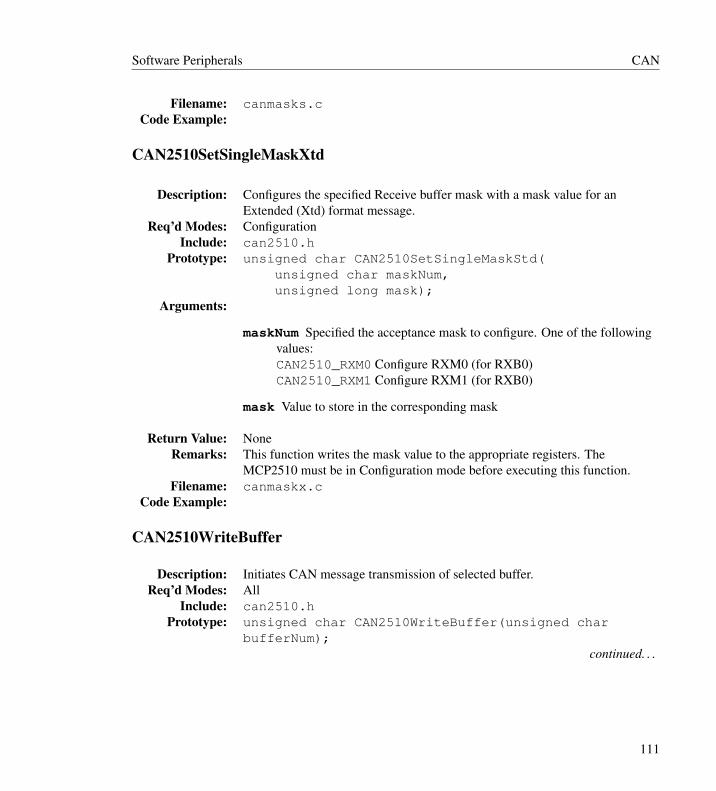
Software Peripherals CAN
Filename: canmasks.cCode Example:
CAN2510SetSingleMaskXtd
Description: Configures the specified Receive buffer mask with a mask value for anExtended (Xtd) format message.
Req’d Modes: ConfigurationInclude: can2510.h
Prototype: unsigned char CAN2510SetSingleMaskStd(unsigned char maskNum,unsigned long mask);
Arguments:
maskNum Specified the acceptance mask to configure. One of the followingvalues:CAN2510_RXM0 Configure RXM0 (for RXB0)CAN2510_RXM1 Configure RXM1 (for RXB0)
mask Value to store in the corresponding mask
Return Value: NoneRemarks: This function writes the mask value to the appropriate registers. The
MCP2510 must be in Configuration mode before executing this function.Filename: canmaskx.c
Code Example:
CAN2510WriteBuffer
Description: Initiates CAN message transmission of selected buffer.Req’d Modes: All
Include: can2510.hPrototype: unsigned char CAN2510WriteBuffer(unsigned char
bufferNum);continued. . .
111
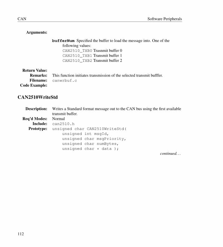
CAN Software Peripherals
Arguments:
bufferNum Specified the buffer to load the message into. One of thefollowing values:CAN2510_TXB0 Trasnmit buffer 0CAN2510_TXB1 Transmit buffer 1CAN2510_TXB2 Transmit buffer 2
Return Value:Remarks: This function initiates transmission of the selected transmit bufffer.Filename: canwrbuf.c
Code Example:
CAN2510WriteStd
Description: Writes a Standard format message out to the CAN bus using the first availabletransmit buffer.
Req’d Modes: NormalInclude: can2510.h
Prototype: unsigned char CAN2510WriteStd(unsigned int msgId,unsigned char msgPriority,unsigned char numBytes,unsigned char * data );
continued. . .
112

Software Peripherals CAN
Arguments:
msgID CAN message identifier, 11 bits for a standard message. This 11-bitidentifier is stored in the lower 11 bits of msgId (an unsigned integer).
msgPriority Priority of buffer. One of the following values:CAN2510_PRI_HIGHEST Highest message priorityCAN2510_PRI_HIGH High intermediate message priorityCAN2510_PRI_LOW Low intermediate message priorityCAN2510_PRI_LOWEST Lowest message priority
numBytes Number of bytes of data to transmit, from 0 to 8. If value isgreater than 8, only the first 8 bytes of data will be sent.
data Array of data values to be written. Must be at least as large as the valuespecified in numBytes.
Return Value: Value indicates which buffer was used to transmit the message (0, 1 or 2).-1 indicates that no message was sent.
Remarks: This function will query each transmit buffer for a pending message, and willpost the specified message into the first available buffer.
Filename: canwrits.cCode Example:
CAN2510WriteXtd
Description: Writes a Extended format message out to the CAN bus using the firstavailable transmit buffer.
Req’d Modes: NormalInclude: can2510.h
Prototype: unsigned char CAN2510WriteXtd(unsigned long msgId,unsigned char msgPriority,unsigned char numBytes,unsigned char * data );
continued. . .
113
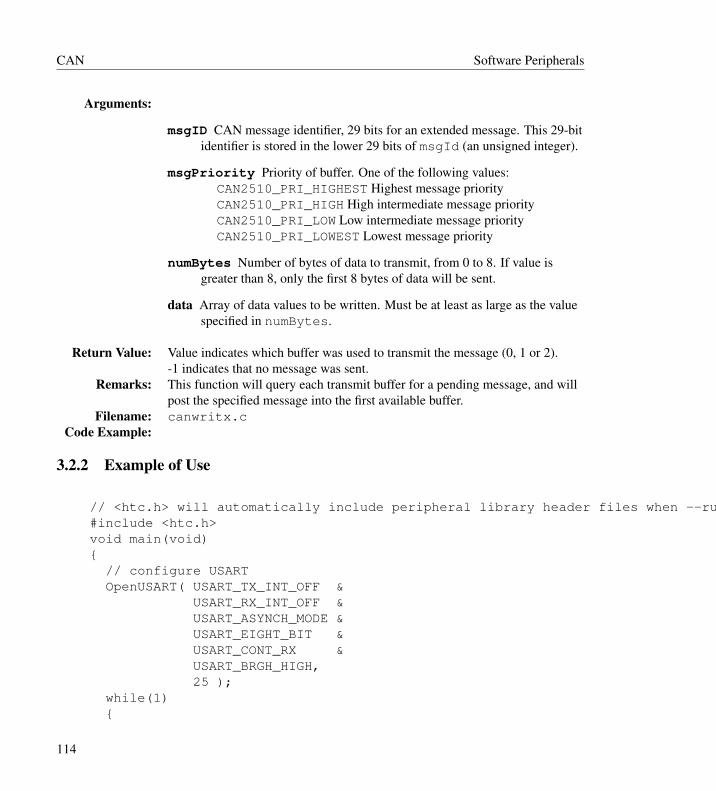
CAN Software Peripherals
Arguments:
msgID CAN message identifier, 29 bits for an extended message. This 29-bitidentifier is stored in the lower 29 bits of msgId (an unsigned integer).
msgPriority Priority of buffer. One of the following values:CAN2510_PRI_HIGHEST Highest message priorityCAN2510_PRI_HIGH High intermediate message priorityCAN2510_PRI_LOW Low intermediate message priorityCAN2510_PRI_LOWEST Lowest message priority
numBytes Number of bytes of data to transmit, from 0 to 8. If value isgreater than 8, only the first 8 bytes of data will be sent.
data Array of data values to be written. Must be at least as large as the valuespecified in numBytes.
Return Value: Value indicates which buffer was used to transmit the message (0, 1 or 2).-1 indicates that no message was sent.
Remarks: This function will query each transmit buffer for a pending message, and willpost the specified message into the first available buffer.
Filename: canwritx.cCode Example:
3.2.2 Example of Use
// <htc.h> will automatically include peripheral library header files when --runtime=+plib is used.#include <htc.h>void main(void){
// configure USARTOpenUSART( USART_TX_INT_OFF &
USART_RX_INT_OFF &USART_ASYNCH_MODE &USART_EIGHT_BIT &USART_CONT_RX &USART_BRGH_HIGH,25 );
while(1){
114

Software Peripherals I2C
while( ! PORTAbits.RA0 ); //wait for RA0 highWriteUSART( PORTD ); //write value of PORTDif(PORTD == 0x80) // check for termination
break; // value}CloseUSART();
}
3.3 I2C
Macros for Selecting I2C Pin AssignmentThe precompiled versions of these functions use default pin assignments that can be changed byredefining the following macro assignments in the file sw_i2c.h, found in the h subdirectory ofthe compiler installation:
I2C Line Macros Default Value UseDATA Pin DATA_PIN
DATA_LATDATA_LOWDATA_HI
PORTBbits.RB4LATBbits.RB4TRISBbits.TRISB4 =0;TRISBbits.TRISB4 =1;
Pin used for the DATA line.Latch associated withDATA pin.Statement to configure theDATA pin as an output.Statement to configure theDATA pin as an input.
CLOCKPin
SCLK_PINSCLK_LATCLOCK_LOWCLOCK_HI
PORTBbits.RB3LATBbits.LATB3TRISBbits.TRISB3 =0;TRISBbits.TRISB3 =1;
Pin used for the CLOCKline.Latch associated withCLOCK pin.Statement to configure theCLOCK pin as an output.Statement to configure theCLOCK pin as an input.
After these definitions have been made, the user must recompile the I2C routines and then usethe updated files in the project. This can be accomplished by adding the library source files into theproject or by recompiling the library files using the provided batch files.
115
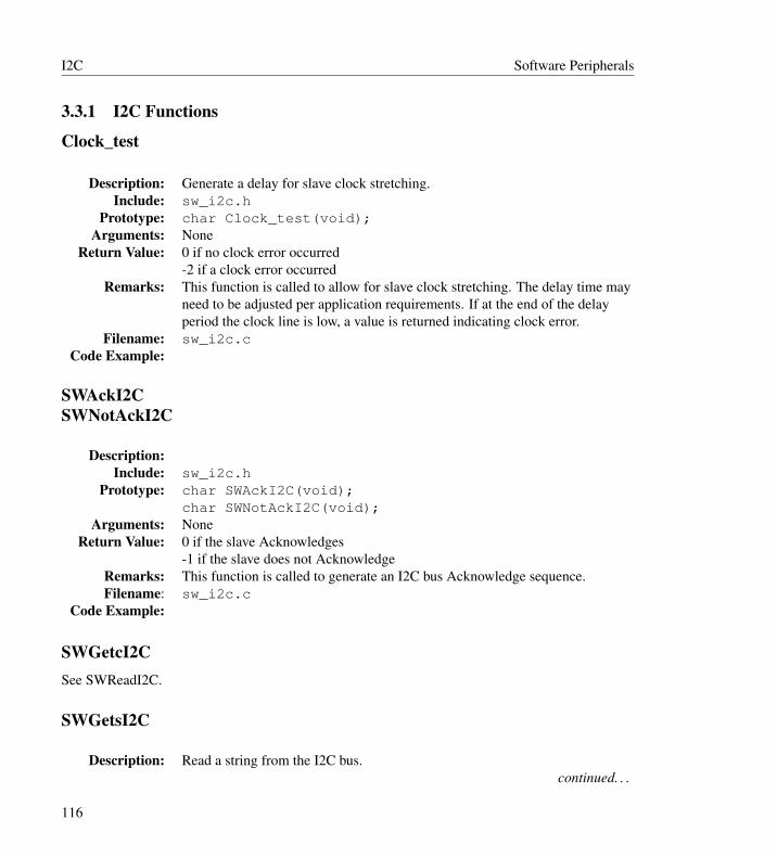
I2C Software Peripherals
3.3.1 I2C Functions
Clock_test
Description: Generate a delay for slave clock stretching.Include: sw_i2c.h
Prototype: char Clock_test(void);Arguments: None
Return Value: 0 if no clock error occurred-2 if a clock error occurred
Remarks: This function is called to allow for slave clock stretching. The delay time mayneed to be adjusted per application requirements. If at the end of the delayperiod the clock line is low, a value is returned indicating clock error.
Filename: sw_i2c.cCode Example:
SWAckI2CSWNotAckI2C
Description:Include: sw_i2c.h
Prototype: char SWAckI2C(void);char SWNotAckI2C(void);
Arguments: NoneReturn Value: 0 if the slave Acknowledges
-1 if the slave does not AcknowledgeRemarks: This function is called to generate an I2C bus Acknowledge sequence.Filename: sw_i2c.c
Code Example:
SWGetcI2CSee SWReadI2C.
SWGetsI2C
Description: Read a string from the I2C bus.continued. . .
116

Software Peripherals I2C
Include: sw_i2c.hPrototype: char SWGetsI2C(
unsigned char * rdptr,unsigned char length );
Arguments:
rdptr Location to store the data read from the I2C bus
length Number of bytes to read
Return Value: -1 if the master generated a NOT ACK bus condition before all bytes havebeen received0 otherwise
Remarks: This function reads in a string of predetermined length.Filename: sw_i2c.c
Code Example: char x[10];SWGetsI2C(x, 5);
SWNotAckI2CSee SWAckI2C.
SWPutcI2CSee SWWriteI2C.
SWPutsI2C
Description: Write a string to the I2C bus.Include: sw_i2c.h
Prototype: char SWPutsI2C(unsigned char * wrdptr);Arguments:
wrdptr Pointer to data to be written to the I2C bus
Return Value: -1 if there was an error writing to the I2C bus0 otherwise
Remarks: This function writes out a data string up to (but not including) a null character.Filename: sw_i2c.c
continued. . .
117

I2C Software Peripherals
Code Example: char mybuff[] = “hello”;SWPutsI2C(mybuff);
SWReadI2CSWGetcI2C
Description: Read a data byte from the I2C bus.Include: sw_i2c.h
Prototype: unsigned int SWReadI2C(void);Arguments: None
Return Value: This function returns the acquired I2C data byte.-1 if there was an error in this function.
Remarks: This function reads in a single data byte by generating the appropriate signalson the predefined I2C clock line. This function may need to be modifiedbased on the oscillator frequency.
nFilename: sw_i2c.cCode Example:
SWRestartI2C
Description: Generate an I2C bus Restart conditionInclude: sw_i2c.h
Prototype: void SWRestartI2C(void);Arguments: None
Return Value: NoneRemarks: This function is called to generate an I2C bus restart condition.Filename: sw_i2c.c
Code Example:
SWStartI2C
Description: Generate an I2C bus Start conditionInclude: sw_i2c.h
Prototype: void SWStartI2C(void);Arguments: None
Return Value: Nonecontinued. . .
118

Software Peripherals I2C
Remarks: This function is called to generate an I2C bus start condition.Filename: sw_i2c.c
Code Example:
SWStopI2C
Description: Generate an I2C bus Stop conditionInclude: sw_i2c.h
Prototype: void SWStopI2C(void);Arguments: None
Return Value: NoneRemarks: This function is called to generate an I2C bus stop condition.Filename: sw_i2c.c
Code Example:
SWWriteI2CSWPutcI2C
Description: Write a byte to the I2C bus.Include: sw_i2c.h
Prototype: char SWWriteI2C(unsigned char data_out);Arguments:
data_out The single data byte to be written to the I2C bus.
Return Value: 0 if write is successful-1 if there was an error condition
Remarks: This function writes out a single data byte to the predefined data pin.Filename: sw_i2c.c
Code Example: if(SWWriteI2C(0x80))errorHandler();
3.3.2 Example of Use
// <htc.h> will automatically include peripheral library header files when --runtime=+plib is used.#include <htc.h>// FUNCTION Prototype
119

I2C Software Peripherals
void byte_write(void);void page_write(void);void current_address(void);void random_read(void);void sequential_read(void);void ack_poll(void);unsigned char warr[] = {8,7,6,5,4,3,2,1,0};unsigned char rarr[15];unsigned char far *rdptr = rarr;unsigned char far *wrptr = warr;unsigned char var;#define W_CS PORTA.2//**************************************************void main( void ){
byte_write();ack_poll();page_write();ack_poll();Nop();sequential_read();Nop();while (1); // Loop indefinitely
}void byte_write( void ){
SWStartI2C();var = SWPutcI2C(0xA0); // control byteSWAckI2C();var = SWPutcI2C(0x10); // word addressSWAckI2C();var = SWPutcI2C(0x66); // dataSWAckI2C();SWStopI2C();
}void page_write( void ){
SWStartI2C();var = SWPutcI2C(0xA0); // control byte
120
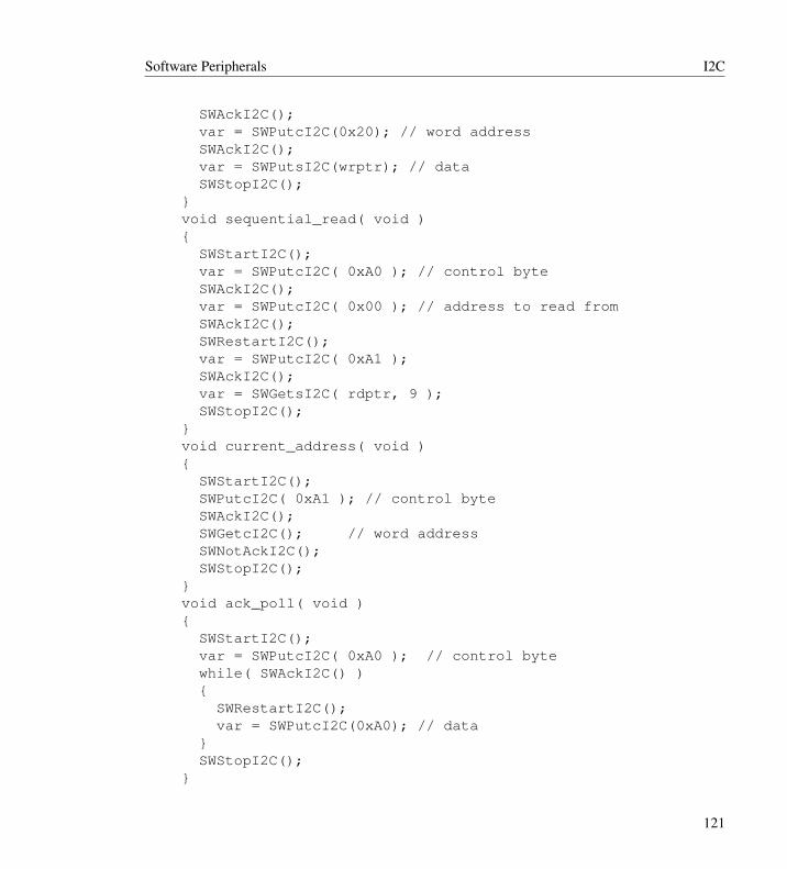
Software Peripherals I2C
SWAckI2C();var = SWPutcI2C(0x20); // word addressSWAckI2C();var = SWPutsI2C(wrptr); // dataSWStopI2C();
}void sequential_read( void ){
SWStartI2C();var = SWPutcI2C( 0xA0 ); // control byteSWAckI2C();var = SWPutcI2C( 0x00 ); // address to read fromSWAckI2C();SWRestartI2C();var = SWPutcI2C( 0xA1 );SWAckI2C();var = SWGetsI2C( rdptr, 9 );SWStopI2C();
}void current_address( void ){
SWStartI2C();SWPutcI2C( 0xA1 ); // control byteSWAckI2C();SWGetcI2C(); // word addressSWNotAckI2C();SWStopI2C();
}void ack_poll( void ){
SWStartI2C();var = SWPutcI2C( 0xA0 ); // control bytewhile( SWAckI2C() ){
SWRestartI2C();var = SWPutcI2C(0xA0); // data
}SWStopI2C();
}
121
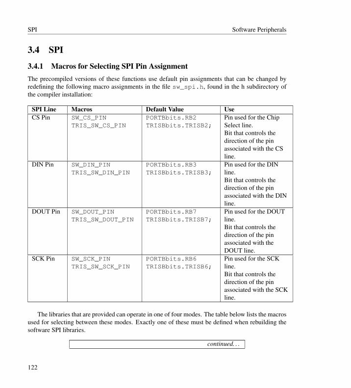
SPI Software Peripherals
3.4 SPI
3.4.1 Macros for Selecting SPI Pin AssignmentThe precompiled versions of these functions use default pin assignments that can be changed byredefining the following macro assignments in the file sw_spi.h, found in the h subdirectory ofthe compiler installation:
SPI Line Macros Default Value UseCS Pin SW_CS_PIN
TRIS_SW_CS_PINPORTBbits.RB2TRISBbits.TRISB2;
Pin used for the ChipSelect line.Bit that controls thedirection of the pinassociated with the CSline.
DIN Pin SW_DIN_PINTRIS_SW_DIN_PIN
PORTBbits.RB3TRISBbits.TRISB3;
Pin used for the DINline.Bit that controls thedirection of the pinassociated with the DINline.
DOUT Pin SW_DOUT_PINTRIS_SW_DOUT_PIN
PORTBbits.RB7TRISBbits.TRISB7;
Pin used for the DOUTline.Bit that controls thedirection of the pinassociated with theDOUT line.
SCK Pin SW_SCK_PINTRIS_SW_SCK_PIN
PORTBbits.RB6TRISBbits.TRISB6;
Pin used for the SCKline.Bit that controls thedirection of the pinassociated with the SCKline.
The libraries that are provided can operate in one of four modes. The table below lists the macrosused for selecting between these modes. Exactly one of these must be defined when rebuilding thesoftware SPI libraries.
continued. . .
122

Software Peripherals SPI
Macro Default Value MeaningMODE0 defined CKP=0
CKE = 0MODE1 not defined CKP=1
CKE = 0MODE2 not defined CKP=0
CKE = 1MODE3 not defined CKP=1
CKE = 1
After these definitions have been made, the user must recompile the SPI routines and then usethe updated files in the project. This can be accomplished by adding the library source files into theproject or by recompiling the library files using the provided batch files.
3.4.2 SPI Functions
ClearCSSWSPI
Description: Clear the Chip Select (CS) pin that is specified in the sw_spi.h header file.Include: sw_spi.h
Prototype: void ClearCSSWSPI(void);Arguments: None
Return Value: NoneRemarks: This macro clears the I/O pin that is specified in sw_spi.h to be the Chip
Select (CS) pin for the software SPI. By default this pin is RC3 for18FXXK50 and 18FXXK22 family devices, and RB2 for all other devices.
Filename: clrcsspi.cCode Example:
OpenSWSPI
Description: Configure the I/O pins for the software SPI.Include: sw_spi.h
Prototype: void OpenSWSPI(void);Arguments: None
Return Value: Nonecontinued. . .
123
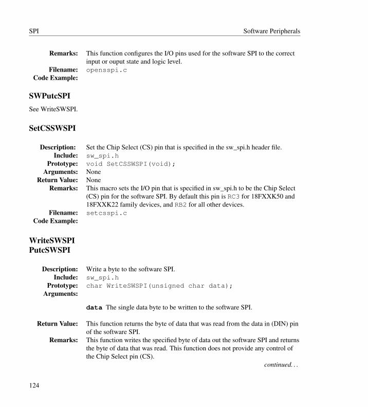
SPI Software Peripherals
Remarks: This function configures the I/O pins used for the software SPI to the correctinput or ouput state and logic level.
Filename: opensspi.cCode Example:
SWPutcSPISee WriteSWSPI.
SetCSSWSPI
Description: Set the Chip Select (CS) pin that is specified in the sw_spi.h header file.Include: sw_spi.h
Prototype: void SetCSSWSPI(void);Arguments: None
Return Value: NoneRemarks: This macro sets the I/O pin that is specified in sw_spi.h to be the Chip Select
(CS) pin for the software SPI. By default this pin is RC3 for 18FXXK50 and18FXXK22 family devices, and RB2 for all other devices.
Filename: setcsspi.cCode Example:
WriteSWSPIPutcSWSPI
Description: Write a byte to the software SPI.Include: sw_spi.h
Prototype: char WriteSWSPI(unsigned char data);Arguments:
data The single data byte to be written to the software SPI.
Return Value: This function returns the byte of data that was read from the data in (DIN) pinof the software SPI.
Remarks: This function writes the specified byte of data out the software SPI and returnsthe byte of data that was read. This function does not provide any control ofthe Chip Select pin (CS).
continued. . .
124
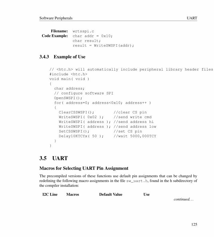
Software Peripherals UART
Filename: wrtsspi.cCode Example: char addr = 0x10;
char result;result = WriteSWSPI(addr);
3.4.3 Example of Use
// <htc.h> will automatically include peripheral library header files when --runtime=+plib is used.#include <htc.h>void main( void ){
char address;// configure software SPIOpenSWSPI();for( address=0; address<0x10; address++ ){
ClearCSSWSPI(); //clear CS pinWriteSWSPI( 0x02 ); //send write cmdWriteSWSPI( address ); //send address hiWriteSWSPI( address ); //send address lowSetCSSWSPI(); //set CS pinDelay10KTCYx( 50 ); //wait 5000,000TCY
}}
3.5 UART
Macros for Selecting UART Pin AssignmentThe precompiled versions of these functions use default pin assignments that can be changed byredefining the following macro assignments in the file sw_uart.h, found in the h subdirectory ofthe compiler installation:
I2C Line Macros Default Value Usecontinued. . .
125

UART Software Peripherals
TX Pin SWTXDSWTXDpiTRIS_SWTXD
PORTB4TRISB
Port used for the transmit line.Bit in the SWTXD port usedfor the TX line.Data Direction registerassociated with the port usedfor the TX line.
RX Pin SWRXDSWRXDpinTRIS_SWRXD
PORTB5TRISB
Port used for the receive line.Bit in the SWRXD port usedfor the RX line.Data Direction registerassociated with the port usedfor the RX line.
After these definitions have been made, the user must recompile the UART routines and then usethe updated files in the project. This can be accomplished by adding the library source files into theproject or by recompiling the library files using the provided batch files.
The UART libraries also require that the following functions be defined by the user to providethe appropriate delays:
Function BehaviorDelayTXBitUART Delay for ((((2*FOSC) / (4*baud)) + 1) / 2) - 12 cyclesDelayRXHalfBitUART Delay for ((((2*FOSC) / (8*baud)) + 1) / 2) - 9 cyclesDelayRXBitUART Delay for ((((2*FOSC) / (4*baud)) + 1) / 2) - 14 cycles
3.5.1 I2C Functions
getcUARTSee ReadUART.
getsUART
Description: Read a string from the software UART.Include: sw_uart.h
Prototype: void getsUART(unsigned char * buffer,unsigned char len );
continued. . .
126
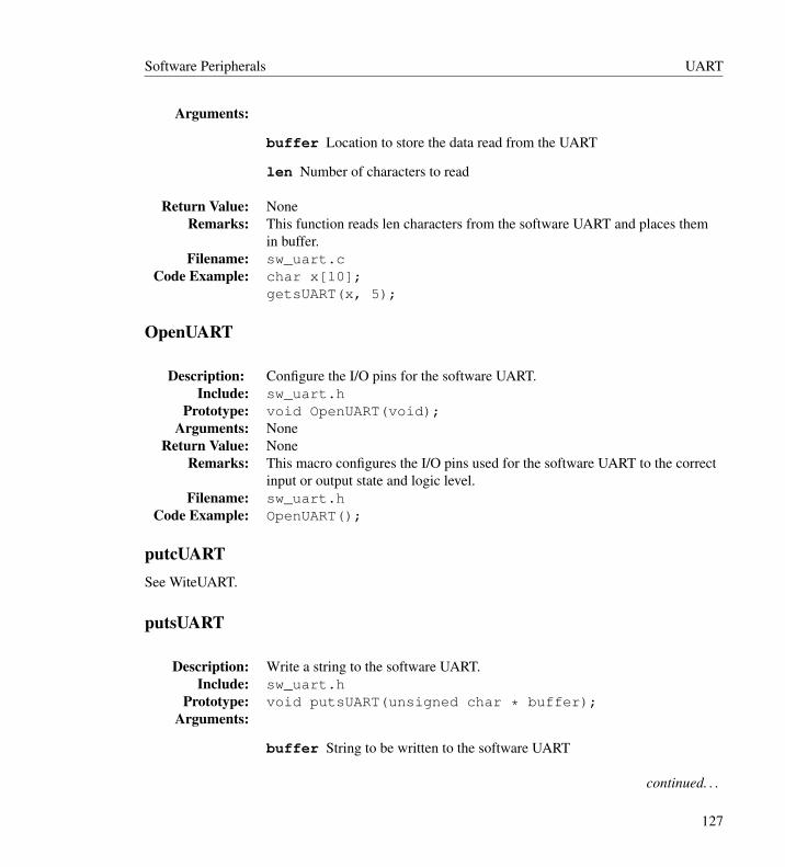
Software Peripherals UART
Arguments:
buffer Location to store the data read from the UART
len Number of characters to read
Return Value: NoneRemarks: This function reads len characters from the software UART and places them
in buffer.Filename: sw_uart.c
Code Example: char x[10];getsUART(x, 5);
OpenUART
Description: Configure the I/O pins for the software UART.Include: sw_uart.h
Prototype: void OpenUART(void);Arguments: None
Return Value: NoneRemarks: This macro configures the I/O pins used for the software UART to the correct
input or output state and logic level.Filename: sw_uart.h
Code Example: OpenUART();
putcUARTSee WiteUART.
putsUART
Description: Write a string to the software UART.Include: sw_uart.h
Prototype: void putsUART(unsigned char * buffer);Arguments:
buffer String to be written to the software UART
continued. . .
127
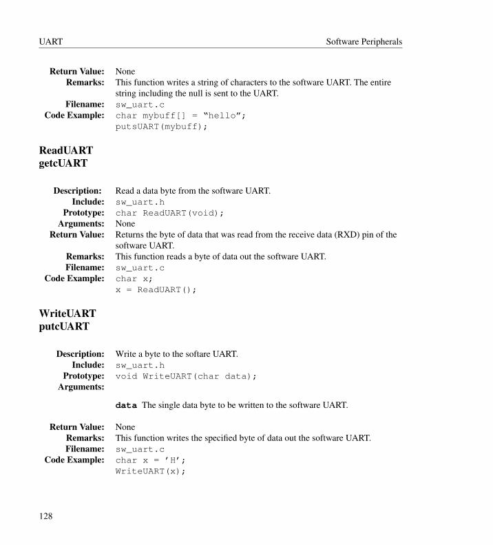
UART Software Peripherals
Return Value: NoneRemarks: This function writes a string of characters to the software UART. The entire
string including the null is sent to the UART.Filename: sw_uart.c
Code Example: char mybuff[] = “hello”;putsUART(mybuff);
ReadUARTgetcUART
Description: Read a data byte from the software UART.Include: sw_uart.h
Prototype: char ReadUART(void);Arguments: None
Return Value: Returns the byte of data that was read from the receive data (RXD) pin of thesoftware UART.
Remarks: This function reads a byte of data out the software UART.Filename: sw_uart.c
Code Example: char x;x = ReadUART();
WriteUARTputcUART
Description: Write a byte to the softare UART.Include: sw_uart.h
Prototype: void WriteUART(char data);Arguments:
data The single data byte to be written to the software UART.
Return Value: NoneRemarks: This function writes the specified byte of data out the software UART.Filename: sw_uart.c
Code Example: char x = ’H’;WriteUART(x);
128

Software Peripherals UART
3.5.2 Example of Use
// <htc.h> will automatically include peripheral library header files when --runtime=+plib is used.#include <htc.h>void main( void ){
char data;// configure software UARTOpenUART();while( 1 ){
data = ReadUART(); //read a byteWriteUART( data ); //bounce it back
}}
129