hheeaattiinngg ... · pdf...
TRANSCRIPT

Department of Climate Change & Energy EfficiencyNovember 2010
HHHeeeaaatttiiinnnggg,,, VVVeeennntttiiilllaaatttiiiooonnn aaannnddd AAAiiirrr CCCooonnndddiiitttiiiooonnniiinnnggg HHHiiiggghhhEEEffffffiiiccciiieeennncccyyy SSSyyysssttteeemmmsss SSStttrrraaattteeegggyyy --- CCCooodddeee ooofff BBBeeesssttt PPPrrraaaccctttiiiccceeefffooorrr MMMaaaiiinnnttteeennnaaannnccceee aaannnddd OOOpppeeerrraaatttiiiooonnn PPPrrrooojjjeeecccttt --- PPPhhhaaassseee 111
04/11/10 - Draft Code V8 - Industry Consultation
i61/25348/101730 Heating, Ventilation and Air Conditioning High Efficiency Systems Strategy - Code of Best Practice forMaintenance and Operation Project - Phase 104/11/10 - Draft Code V8 - Industry Consultation
Foreword
The maintenance and operation of heating ventilation and air conditioning (HVAC) systems incommercial buildings has traditionally been carried out with a focus on statutory requirements,occupational health and safety, reliability, maintaining occupant comfort conditions and the lowest tendercost for the maintenance contract. Often, opportunities for achieving energy & water efficiency gains areneglected and life cycle costs are not given due consideration. The consequences of higher energy &water costs have been accepted as being ‘inevitable’ and passed on to tenants.
The importance of sustainability in commercial buildings has now been pushed to the forefront.
Why Consider Energy & Water Efficiency in Maintenance and Operation?
The need to reduce the environmental footprint of commercial buildings has become an importantpart of strategies presented by Federal, State and Local Governments towards their commitment toaddress climate change, which is now a political issue important to the community.
Efficiencies are achievable across all grades of buildings from Premium Grade CBD properties torural or remote sites.
Commercial buildings are now being designed to comply with building performance rating systemsincluding Green Star and NABERS. The ability of buildings to actually perform efficiently ratherthan having the potential to be efficient is being scrutinised, verified and publicised as neverbefore. Proper Maintenance and Operation of HVAC systems are essential to deliver goodenvironmental performance.
Policies, including Energy Efficiency in Government Operations (EEGO) and other Local Governmentdirectives mandate that Government and State tenants only occupy buildings that have ademonstrated low impact on the environment, such as a 4.5 star or higher NABERS energy ratingor a 4 star NABERS water rating.
The Commercial Building Disclosure (CBD) regulations mandate the energy performance of buildingsto be disclosed and publicly displayed, thereby commercially incentivising energy efficiency.
Private tenants and companies are now demanding to occupy sustainable buildings. This isdriven by an interest to ‘do the right thing’ and corporate commitments to minimise environmentalimpact.
Reduced operating costs with long term financial and other benefits including comfort andreliability for building owners and tenants together with a better retention of asset value.
The HVAC maintenance industry is well placed to make a significant contribution towards reducing theenvironmental impact of buildings. By partnering with facilities managers, maintenance providers canproactively identify, promote and implement cost-effective measures that reduce energy & waterwastage. However, under the constraints of competitive tendering, setting up and delivering maintenancecontracts that successfully reduce a buildings environmental footprint and deliver long term cost savingsis often hampered. Typical maintenance specifications do not focus on achieving energy & waterefficiencies. Contracts often include penalty clauses for non performance on reliability and maintainingcomfort conditions but have no incentives for key people engaged in carrying out maintenance activitiesto actively champion energy & water efficiency during their day-to-day activities.

ii61/25348/101730 Heating, Ventilation and Air Conditioning High Efficiency Systems Strategy - Code of Best Practice forMaintenance and Operation Project - Phase 104/11/10 - Draft Code V8 - Industry Consultation
For buildings to deliver efficiencies and to achieve target performance ratings, it is essential that allstakeholders work in partnership towards making the necessary changes to overcome hurdles andachieve the common goal. This Code of Best Practice for Maintenance and Operation of HVACSystems in Commercial Buildings is intended to be a change accelerator by bringing a sharper focusto energy and water efficiency when maintaining and operating HVAC systems in commercial buildings.
This code provides Building Owners and Facility Managers with information and guidance on setting upmaintenance contracts that actually reduce a building’s environmental impact and achieve cost savings.Advice is given on how to set up environmental performance benchmarks and monitoring, targetimprovements and verify the results in a credible manner. Practical measures are suggested which areintended to assist Contractors to proactively identify energy & water saving opportunities duringmaintenance and operational activities and to add value to their work by partnering with FacilitiesManagers to implement these measures. Designers of HVAC systems and Commissioning Specialistswill also benefit from the technical advice and checklists provided in this code.
This code is applicable towards getting the best results out of existing maintenance contracts as well assetting up and managing future maintenance contracts, the advice being applicable to older facilities andnew.
Industry Reference Group
Australian Institute of Refrigeration, Airconditioning and Heating - Phil Wilkinson
Chartered Institute of Building Services Engineers - Peter Kinsella
Colliers International - John Pirovich
Department for Transport Energy and Infrastructure (SA) - Frank Parrello
Facility Management Association of Australia - Bryon Price
Green Building Council of Australia - Andrew Aitken
Green Leases - Lloyd Woodford
Jones Lang LaSalle – Chris Wallbank
Property Council of Australia - Bryon Price
ACMV Design Consultants - Glen Tatum
Acknowledgements
Editor
iii61/25348/101730 Heating, Ventilation and Air Conditioning High Efficiency Systems Strategy - Code of Best Practice forMaintenance and Operation Project - Phase 104/11/10 - Draft Code V8 - Industry Consultation
Project Background - Heating, Ventilation and AirConditioning – High Efficiency System Strategy (HVACHESS)
The project is funded under a three-year Cool Efficiency Program which is part of the NationalFramework for Energy Efficiency (NFEE) Stage 2. The HVAC High Efficiency Systems Strategy (HVACHESS) was endorsed by Australian, state and territory governments in 2005.
The HVAC HESS Implementation Committee aims to drive long term improvements in the energyefficiency of HVAC systems through whole of life improvements in HVAC efficiency, encompassingdesign, manufacture, installation, operation and maintenance. A large part of the gains targeted are inthe maintenance and operation of existing systems in existing buildings, and through the establishmentof national standard systems of documentation of the design, installation, operation and maintenance ofthe equipment.
Key elements include:
Code of best practice for maintenance and operation.
Scope and design of building services log books.
Development and rollout of Cool Efficiency Program for installation and commissioning best practice.
Development of a ‘Calculating Cool’ online tool.
Measurement, monitoring and metering projects.
The HESS has been designed to address many non-technical barriers to efficiency, while identifying andpromoting highly efficient technical solutions, systems optimisation processes, and creating theenvironment in which energy efficiency gains are valued, measurable and sustainable.
Further Information
1. www.ret.gov.au/documents/mce/energy-eff/nfee/committees/hvac/default.html
Disclaimer
The information or advice contained in this document is intended for use only by persons who have hadadequate technical training in the field to which the Code of Practice relates. The document has beencompiled as an aid only and the information or advice should be verified before it is put to use by anyperson. The user should also establish the applicability of the information or advice in relation to anyspecific circumstances. While the information or advice is believed to be correct, GHD and its employeesdisclaim responsibility for any inaccuracies contained within the document including those due to anynegligence in the preparation and publication of the said document.
While reasonable efforts have been made to ensure that the contents of this publication are factuallycorrect, GHD does not accept responsibility for the accuracy or completeness of the contents, and shallnot be liable for any loss or damage that may be occasioned directly or indirectly through the use of, orreliance on, the contents of this publication.

iv61/25348/101730 Heating, Ventilation and Air Conditioning High Efficiency Systems Strategy - Code of Best Practice forMaintenance and Operation Project - Phase 104/11/10 - Draft Code V8 - Industry Consultation

v61/25348/101730 Heating, Ventilation and Air Conditioning High Efficiency Systems Strategy - Code of Best Practice forMaintenance and Operation Project - Phase 104/11/10 - Draft Code V8 - Industry Consultation
Contents
1. Introduction 1
1.1 About this Document 1
1.2 Document Structure 2
1.3 Abbreviations used in this Code 2
1.4 Description of Key Words 3
2. Key Stakeholders and Potential Benefits 8
3. HVAC Equipment and Efficiency 13
3.1 Introduction 13
3.2 Chillers 14
3.3 Cooling Towers 17
3.4 Air Handling Units & VAV Boxes 19
3.5 Boilers 23
3.6 Pumps 24
3.7 Fans 25
3.8 Humidification and De-Humidification 26
3.9 Packaged HVAC Systems 27
3.10 Power Factor Correction 29
3.11 Building Management Systems 29
3.12 Commissioning, Tuning and Retro Commissioning 31
3.13 Develop Policies and Obtain Corporate Support 34
3.14 Develop Maintenance Strategy 35
3.15 Produce an Asset Register 37
3.16 Establish Benchmarks and KPIs 37
3.17 Procure Maintenance Contract 39
3.18 Training 41
3.19 Maintenance Management 41
3.20 Monitoring of Maintenance Contract 42
3.21 Maintenance Audit 42
4. Building Operation 44
5. Documentation 46
5.1 Operating & Maintenance Manuals 46

vi61/25348/101730 Heating, Ventilation and Air Conditioning High Efficiency Systems Strategy - Code of Best Practice forMaintenance and Operation Project - Phase 104/11/10 - Draft Code V8 - Industry Consultation
5.2 Maintenance Log Books 46
5.3 Building User Guides 47
5.4 Tenancy Fit Out Guidelines 47
5.5 Format for Information 48
6. Financial & Environmental Evaluation 49
6.1 Introduction 49
6.2 Simple Payback Period 49
6.3 Net Present Value 49
6.4 Internal Rate of Return 50
6.5 Life Cycle Analysis 50
6.6 Benefits of Economic Analysis 50
6.7 Environmental Evaluation 51
Figure Index
Figure 1 Document Structure 2Figure 2 Team Diagram 8Figure 3 Typical Energy Consumption Breakdown in an Office Building (NSW
Public Works 1993, Building Energy Manual) 13Figure 4 Steps to Maintenance Implementation 33Figure 5 Life Cycle Cost Vs Efficiency 51
Appendices
A Checklist: Building OwnerB Checklist: Facility ManagerC Checklist: TenantD Checklist: Maintenance ProviderE Checklist: Energy & Maintenance AuditorF Checklist: Controls ContractorG Checklist: DesignerH Asset RegisterI Public Submission Form

161/25348/101730 Heating, Ventilation and Air Conditioning High Efficiency Systems Strategy - Code of Best Practice forMaintenance and Operation Project - Phase 104/11/10 - Draft Code V8 - Industry Consultation
1. Introduction
1.1 About this DocumentThis Code focuses on cost effective measures which improve HVAC operation & maintenance, deliveringincreased energy & water efficiencies in new and existing commercial office type buildings. Apart fromincreasing a buildings ‘sustainability’, additional advantages are savings in utility bills & operational costs tothe building owner and tenant together with improved reliability and thermal comfort. Maintenance providerswould benefit as a result of better recognition gained for proper maintenance and from businessopportunities and financial incentives for adding value to existing and new maintenance contracts.
This Code identifies and recognises the importance of existing Australian and International standards andguidelines for maintenance of HVAC systems and attempts to avoid the repetition of material alreadypublished. Existing publications comprehensively cover factors for consideration when setting upmaintenance contracts- including statutory requirements, occupational health and safety, reliability,occupant comfort and contract administration. For the maintenance of HVAC systems in Australia, theavailability of the AIRAH application manual DA19 – HVAC&R Maintenance is acknowledged and this Codeis intended to complement the advice and maintenance schedules already published in DA19.
This Code is applicable to typical HVAC systems that are installed in commercial office type buildings, itapplies to existing buildings- old & new, different grades-premium grade CBD & rural and it includesmeasures that would be beneficial if considered during the design and documentation stages of newprojects. This code does not cover industrial applications and specialist equipment including steam, coal/oilfired boilers, cogeneration/tri-generation and data centres.
This Code can be used by building owners, facility & energy managers, maintenance providers,commissioning specialists, designers and other stakeholders to assist with the following:
Getting the most from existing maintenance contracts to achieve increased energy & water efficienciesfrom HVAC systems. Many of the recommendations in this code are likely to be cost effective towardsdelivering mutual benefits to facility Managers and maintenance providers, operating within existingmaintenance contracts.
Improving the energy and water performance ratings (NABERS energy & water) of existing buildings.
Maintaining the energy and water performance ratings of buildings that are currently delivering the targetrating. Maintaining a building’s performance rating requires efficient operation with regular monitoring ofkey parameters, together with fine-tuning and re-balancing of the HVAC systems. Buildings arebecoming increasingly complex, analogous with aeroplanes requiring ‘fly by wire’ technology in order tostay in the air. An example is failure of humidity control in buildings that have chilled beams and theoccupants getting ‘wet’. This code highlights the value of routine checks and re-tuning towards makingbuildings continue to perform efficiently.
As a source of reference for use when setting up future HVAC maintenance contracts to improve energy& water efficiencies. Technical advice is also provided for designers and commissioning specialists.
Identifying potential energy & water saving opportunities when considering the replacement andupgrading of HVAC systems. This code promotes partnership and collaboration between maintenanceproviders, facility managers and building owners towards achieving energy & water savings from HVACsystems.
Setting up of monitoring systems and key performance indicators (KPIs) to enable the benchmarking ofthe energy performance of buildings and the verification of the effectiveness of measures put in place toimprove energy & water efficiency.

261/25348/101730 Heating, Ventilation and Air Conditioning High Efficiency Systems Strategy - Code of Best Practice forMaintenance and Operation Project - Phase 104/11/10 - Draft Code V8 - Industry Consultation
Maximise the Net Present Value of assets and facilities by identifying capital investment opportunitiesthat will deliver significant savings.
1.2 Document Structure
Figure 1 Document Structure
1.3 Abbreviations used in this CodeAHU Air Handling Unit
AS Australian Standard (AS/NSZ-Australian New Zealand Standard)
AIRAH Australian Institute of Refrigeration, Air-Conditioning and Heating
ASHRAE American Society of Heating, Refrigerating and Air-Conditioning Engineers
BCA Building Code of Australia
BMS Building Management System
CIBSE Chartered Institute of Building Services Engineers
CBD Commercial Building Disclosure
CMMS Computerised Maintenance Management Systems
COP Coefficient of Performance (a measure of efficiency of a chiller)
CFC Chloro Fluoro Carbon (Refrigerant)
DCCEE Department of Climate Change and Energy Efficiency
EEGO Energy Efficiency in Government Operations

361/25348/101730 Heating, Ventilation and Air Conditioning High Efficiency Systems Strategy - Code of Best Practice forMaintenance and Operation Project - Phase 104/11/10 - Draft Code V8 - Industry Consultation
EIR Environmental Impact Rating (a factor that takes into account the environmentalimpact of HVAC equipment in a building)
GBCA Green Building Council Australia
HCFC Hydrogenated Chloro Fluoro Carbon (Refrigerant)
GWP Global Warming Potential
HVAC Heating Ventilation and Air Conditioning
HVCA Heating and Ventilating Contractors’ Association (United Kingdom)
IPLV Integrated Part Load Value (a measure of efficiency of a chiller)
KPI Key Performance Indicator
kWh Unit of energy, typically used for electricity
MJ Unit of energy, typically used for gas. 1MJ=0.278kWh (1GJ=278kWh)
ML Mega Litre, a Million Litres
MEPS Minimum Energy Performance Standards
NABERS National Australian Built Environment Rating System
NGERS National Greenhouse and Energy Reporting System
NLA Net Lettable Area, measured in accordance with the PCA Method of Measurement
ODP Ozone Depletion Potential
PCA Property Council of Australia
PPM Planned Preventative Maintenance
QA Quality Assurance
VSD Variable Speed Drive (also known as Variable Frequency Drive)
1.4 Description of Key WordsKey words used in this Code are described below.
Asset Register
Database (list) of building services equipment (plant), containing information such as equipment function,manufacturer & model, duty, age, cost and location. It is essential to compile a comprehensive assetregister prior to setting up a maintenance contract so that all parties are aware of the equipment covered inthe contract. This Code promotes the inclusion of an environmental impact rating (EIR) for the equipment inthe asset register to identify the performance and potential for upgrade in key HVAC components that havea significant impact on energy & water consumption.
461/25348/101730 Heating, Ventilation and Air Conditioning High Efficiency Systems Strategy - Code of Best Practice forMaintenance and Operation Project - Phase 104/11/10 - Draft Code V8 - Industry Consultation
Base Building Services
Also known as central services. These are common services provided by the building owner that serves alltenancies and include the HVAC systems installed within the tenancies except for supplementary airconditioning installed by the tenants. Most office buildings have “gross” leases where the operating andmaintenance costs associated with providing the base building services are paid by the landlord and thesecosts are included in the rents charged to tenants.
Benchmarking
The comparison of a building’s energy or water consumption with similar buildings and/or industry bestpractices. Typical benchmarks for buildings are expressed in kWh/m² or MJ/m² for energy, kg CO2/m² andML/m² for water. When comparing a buildings energy or water performance with available benchmarks, it isimportant to establish whether the systems are similar and you are comparing ‘apples with apples’ bynormalising for variances such as climate, operating hours and operating conditions.
Building TuningThe process of ongoing monitoring of energy consuming systems during a period (12 months typically) afterinitial commissioning. During this process, the performance of systems is optimised, making adjustments tocontrol algorithms, taking account of issues such as part load performance, seasonal changes intemperature and specific occupant requirements such as after hours operation.
Building Users Guide
A document that is written to assist the users (and service providers) of a building to understand keyfeatures and services that are designed to reduce the environmental impact, including energy & watersaving features. Traditionally, building occupants had no way of obtaining this information apart fromreferencing the operating and maintenance manuals, which by their nature are complex and cumbersomedocuments, not readily accessible to building occupants. The inclusion of a building users guide gains acredit point under the Green Star rating system.
Breakdown MaintenanceAlso known as reactive maintenance. Maintenance where remedial work is carried out upon equipmentfailing in operation (hence unplanned).
If remedial work is carried out to equipment in response to a situation that may have serious consequencessuch as threatening health and safety- this aspect of breakdown maintenance is referred to as emergencymaintenance.
Commercial Building DisclosureCBD is a national energy efficiency program that requires, from the 1st November 2010, for sellers or lessorsof office spaces greater than 2000 m2 to obtain and disclose up to date NABERS energy ratings and from 1st
November 2011 disclose a Building Energy Efficiency Certificate (BEEC). Refer to www.cbd.gov.au for moredetails.
CommissioningCommissioning is carried out after the installation of equipment and systems to ensure that they are testedin operation and perform satisfactorily. For HVAC systems to deliver optimal energy performance, thebalancing of air & water flows to design specifications and the correct setting up of BMS controls form a vitalpart of commissioning.

561/25348/101730 Heating, Ventilation and Air Conditioning High Efficiency Systems Strategy - Code of Best Practice forMaintenance and Operation Project - Phase 104/11/10 - Draft Code V8 - Industry Consultation
Defects Liability Period
A period of time (typically 12 months) following practical completion of a building construction and/or aservices installation, during which a contractor is liable for any issues or defects that arise due to faultyworkmanship or materials. For most HVAC installations, it is normal for the installation contractor to carryout planned maintenance during this period, although in certain circumstances (such as replacement ofexisting plant), the planned maintenance may be carried out by the incumbent maintenance contractor withbreakdowns being rectified by the installation contractor.
Contractors are increasingly being expected to deliver stipulated environmental performances during thedefects liability period and this has brought on a renewed focus on efficient operation and maintenance.
EEGO
Energy efficiency in government operations- applies to all government departments. Mandates signing ofgreen lease schedules for new leases and the achievement of a NABERS energy rating greater than 4.5stars, with a portfolio energy consumption target of 400MJ/m²/Y for base building services in new and re-furbished buildings. Organisations must annually report on-line, their energy performance. Refer towww.greenhouse.gov for further details.
Energy (or Water) AuditA survey and analysis of a building’s energy consumption to establish the building’s energy efficiency whencompared to other similar buildings. An energy audit also identifies energy saving opportunities as aprioritised list with payback periods. Energy Audits are typically carried out in accordance with AS/NZS3598:2000, which describes three levels of energy audit ranging from Level 1 to Level 3 depending on thedepth of analysis. A water audit would focus on water savings. There are no accepted standards for wateraudits although major utility providers have developed templates.
Greenhouse Emission FactorsThese values are published by the DCCEE and are available at www.climatechange.gov.au under NationalGreenhouse Accounts (NGA) Factors. The most common greenhouse gas associated with the operation ofHVAC systems will be CO2, although other emissions such as refrigerants, may be relevant to largerfacilities. CO2 emissions from a facility could be attributed to electricity consumption and the consumption offossil fuels such as gas (for space heating and domestic hot water) and diesel (for standby generators). TheCO2 emissions due to electricity generation vary from state to state, depending on the type of fossil fuelconsumed- brown coal, black coal or natural gas, and the proportion of electricity produced from renewablesources such as hydropower and wind.
Green Lease SchedulesAll new leases >2000m² and >2years that government tenants sign, must have a green lease scheduleincluded in the contract. Green lease schedules place mutual obligations on landlords and tenants toachieve energy efficiency targets of 4.5 stars NABERS or higher. Other requirements include the setting upof Building Management Committees, energy management plans and separate energy metering. Refer towww.climatechange.gov.au for more details.
Green Star
An environmental rating system for offices and other buildings developed by the GBCA. ‘Green Star Office’is specific to office buildings and it gives credits for implementing energy & water saving measures in newand re-furbishment building projects through proper design, installation and commissioning of HVACsystems. Green Star has raised the importance of key issues that have a significant impact on energy &water consumption in buildings, which have traditionally been neglected- such as proper commissioning,fine tuning, and good documentation including the development of Building User Guides. Visitwww.gbca.org.au for more details
661/25348/101730 Heating, Ventilation and Air Conditioning High Efficiency Systems Strategy - Code of Best Practice forMaintenance and Operation Project - Phase 104/11/10 - Draft Code V8 - Industry Consultation
Life Cycle
The time interval between a product’s conception and its disposal. Life cycle costing includes operatingcosts of an asset and is a true representation of cost over the long term rather than using capital or firstcost.
MaintenanceTechnical, administrative, managerial and supervisory activities that are carried out on plant and equipmentin order to retain performance and provide assurance that a system will work as and when required.
Maintenance LogbookA record of ongoing testing, events, parameters, settings including servicing and maintenance- from thedate of installation & commissioning to the end of life of a system. Equipment log books are dedicated tomajor equipment such as chillers, boilers and cooling towers.
Maintenance Policy
A policy developed by the Building Owner that stipulates maintenance requirements and may includereferences to health & safety, energy and environmental policies, giving consideration to any specificrequirements of lease agreements. It is essential for the maintenance policy to incorporate sustainabilityobjectives and obtain corporate endorsement from the highest levels, in order to secure the necessaryfunding and good governance necessary for energy & water efficient maintenance.
NABERS
NABERS is a performance based rating system for existing buildings. NABERS rates a building on the basisof its measured operational impacts on the environment, and provides an indication of how well a building ismanaging these environmental impacts compared with buildings of similar type, in similar geographiclocations. An un-accredited NABERS rating can be performed by anyone, using the online calculator, tocompare the energy or water performance of their building with similar buildings. An accredited NABERSrating, that can be publicly displayed, can only be performed by an accredited NABERS assessor. Refer towww.nabers.com.au for more details.
NGERS
The National Greenhouse and Energy Reporting Act (2007) is a mandatory act administered by the DCCEEfor the reporting of annual greenhouse gas emissions and energy consumption. NGERS applies to facilitiesor corporate groups whose emissions, energy consumption or production levels are higher than theapplicable thresholds. Refer to www.climatechange.gov.au for more details.
Planned Preventative MaintenanceMaintenance that is planned and carried out in a manner that is intended to prevent equipment failure,hence improving reliability and plant availability.
Planned preventative maintenance may be carried out at fixed intervals (or schedules) - hence referred toas scheduled maintenance or when certain pre determined parameters are exceeded- referred to ascondition (or performance) based maintenance. BMS systems can play an important role in condition basedmaintenance, helping to cost effectively improve reliability and efficiency.
Power Factor
Is relevant to the electricity invoice for a facility and is the ratio between true electrical power (kW) /apparentelectrical power (kVA). HVAC equipment have electrical motors (which are called inductive loads) thatreduce a buildings power factor, thereby increasing the maximum electricity demand kVA. Some electricitysuppliers charge for the monthly maximum demand kVA, in addition to the electrical energy (kWh)consumed and should this be the case, these demand charges are identified separately on the utility bill. It

761/25348/101730 Heating, Ventilation and Air Conditioning High Efficiency Systems Strategy - Code of Best Practice forMaintenance and Operation Project - Phase 104/11/10 - Draft Code V8 - Industry Consultation
is essential for Facilities Managers to be aware whether maximum demand charges are applicable to abuilding and if so, to monitor the power factor. Failure of power factor correction equipment can be veryexpensive in terms of maximum demand charges. Improving power factor in buildings, reduces constraintsto the electricity supply distribution networks
Service Level AgreementA negotiated agreement between the building owner and/or tenant and the maintenance provider, whichdefines the level to which the performance and condition of the plant and equipment will be maintained,together with the maintenance strategies.
Supplementary HVAC
These are HVAC systems installed, operated and maintained by the tenant to serve specific requirementssuch as meeting rooms having high occupant densities and computer rooms. Supplementary HVACsystems are powered through the tenant’s utility meter(s). Some supplementary HVAC systems areconnected to certain base building services operated by the Landlord. These include the tenant’s condenserwater loop and tenant’s supplementary fresh air and exhaust air. The proper operation of supplementaryHVAC systems is important to prevent energy wastage by these systems counteracting or ‘fighting’ the basebuilding systems.

861/25348/101730 Heating, Ventilation and Air Conditioning High Efficiency Systems Strategy - Code of Best Practice forMaintenance and Operation Project - Phase 104/11/10 - Draft Code V8 - Industry Consultation
2. Key Stakeholders and Potential Benefits
There are a number of Stakeholders who can take positive action to improve energy & water efficiency incommercial buildings and to whom the guidance in this Code would be beneficial. These are identifiedbelow with potential benefits highlighted.
Figure 2 Team Diagram
Building Owner
The building owner is a person or organisation that has ownership of the building and ultimate responsibilityfor legal and compliance issues. The building owner has the most influence for making buildingssustainable. The owner has the potential to motivate and empower all stakeholders from concept designstage through to operation & maintenance. For a building to perform efficiently, teamwork is essential and itis important for the building owner to ensure that the necessary resources are available and thestakeholders carry out their responsibilities. The building owner pays for the operation & maintenance ofHVAC systems installed, including statutory compliance, contractual obligations to tenants and systemefficiencies, therefore is entitled to receive a satisfactory outcome.
The building owner is responsible for setting maintenance and environmental objectives and for drivingbuilding energy & water efficiency initiatives.
Benefits
Encourages building owners to motivate key stakeholders to deliver Energy & Water efficiencies.
Promotes teamwork, which is essential for efficient building operation and maintenance.
Reduced HVAC life cycle costs & lower outgoings- higher profitability.
Improved building performance ratings, better reliability, greater tenant satisfaction- higher potentialrents and asset value.
Checklist provides a quick reference to key issues that must be in place for efficiencies to be gainedfrom maintenance contracts.

961/25348/101730 Heating, Ventilation and Air Conditioning High Efficiency Systems Strategy - Code of Best Practice forMaintenance and Operation Project - Phase 104/11/10 - Draft Code V8 - Industry Consultation
Facility Manager
A person or organisation employed by the building owner, to be responsible for the operation of a building(or facility) and its services. The Facility Manager’s responsibilities could range from day to day operation &maintenance, complying with statutory requirements, strategic planning and management of maintenance &energy efficiency initiatives.
Benefits
Obtaining the maximum potential from existing maintenance contracts with regards to energy & waterefficiency, by identifying measures that are low cost and easy to implement.
Provides information on energy & water efficiency issues which must be considered when setting upfuture maintenance contracts.
Highlights issues to consider when signing new leases with tenants- “Tenancy Rules” for sustainability.
Assists with setting up contracts that empower and encourage maintenance contractors to ‘partner’ withthe facility managers in order to deliver system efficiencies.
Checklists provide quick references to identify measures which are likely to be cost effective, easy toimplement and deliver quick results.
Provides information on monitoring the effectiveness of the maintenance contractor in reducing energy& water consumption.
Energy Manager
A person appointed by the building owner or facility manager, to focus on reducing energy (and water) costsand consumption. The Energy Manager has responsibility for the purchase of energy and for monitoring andcontrol of energy consumption and costs through the implementation of energy management policies andstrategies that deliver efficiencies. In smaller premises, the role of energy manager is likely to be combinedwith the role of the facility manager.
Benefits
Suggests possible benchmarks and performance indicators that can be used for setting up targets andmonitoring the effects of sustainability measures implemented.
Assists with achieving NABERS energy and NABERS water ratings by providing a set of monitoringtools for tracking actual verses target performance and diagnostic tools for investigating nonperformance.
Provides a set of easy to implement measures that can deliver quick results towards improving abuildings sustainability performance.
Provides a set of benchmarks and KPIs for monitoring the performance of maintenance contractors indelivering energy & water efficiency.
Provides possible frameworks for offering financial incentives in contracts that deliver systemefficiencies and improve building environmental performance ratings.
Tenant
The Tenant is the ultimate Client who pays rent to the building owner for the right to occupy the tenantedarea for the lease period. The tenant pays the utility bills for energy supplied to the tenancy and consumedby tenants lighting and power. The tenant also has responsibility for the installation, maintenance andoperation (including energy costs) associated with supplementary HVAC systems.

1061/25348/101730 Heating, Ventilation and Air Conditioning High Efficiency Systems Strategy - Code of Best Practice forMaintenance and Operation Project - Phase 104/11/10 - Draft Code V8 - Industry Consultation
The Tenant has influence on the correct selection of office equipment (such as computers) and behaviouralissues within the tenancies that affect the energy performance of the tenancy- typically measured by aNABERS energy tenancy rating. The tenant also can have a significant impact on the efficiency of the basebuilding HVAC systems through operational and behavioural issues.
Increasingly, tenants are demanding the buildings they occupy, to be environmentally friendly. This isstimulating other stakeholders to take action on achieving energy and water efficiencies.
Benefits:
A source of reference and checklist to identify energy & water saving measures for discussion inBuilding Management Committees as required in Green Lease Schedules.
Reduced HVAC operating costs for the base building- possible rent reductions to be negotiated with theLandlord, due to lower outgoings.
Reduced operating costs in tenancy due to improved system efficiencies in supplementary HVACsystems.
Improved sustainability performance in tenancy and base building- achievement of corporatecommitments.
Checklist for building operational issues related to occupant behaviour that affects energy consumptionin tenancy and the base building.
Improved plant reliability and occupant comfort. Greater tenant satisfaction and increased workplaceproductivity.
Designer
The designer is engaged by the building owner or developer and has responsibility for evaluating systemrequirements in accordance with the design brief, performing calculations and issuing drawings andspecifications to be used by the installer for the construction of a building and its systems. For HVACsystems to be operated and maintained in a manner that delivers energy & water savings, the starting pointis green design which depends very much on good design. The designer also has a major impact on thelevel of commissioning that is specified and delivered.
Increasingly, design briefs stipulate environmental performance requirements and designers have to focussharply on HVAC systems that actually perform efficiently rather than only have the ability to performefficiently.
Designers must give attention to the correct specification of commissioning and building tuningrequirements, building user guides, operating and maintenance manuals, energy smart controls strategies,monitoring and verification systems together with the necessary sub metering systems- which all have asignificant impact on achieving the full environmental potential of a building.
Benefits Provides a list of energy & water saving measures, including ‘maintainability’ and commission-ability’
that need to be considered during design and documentation stages.
This document and its checklists can be used for design review purposes.
Provides a set of benchmarks and KPIs for demonstrating the effectiveness of measures implementedto deliver system efficiencies.
1161/25348/101730 Heating, Ventilation and Air Conditioning High Efficiency Systems Strategy - Code of Best Practice forMaintenance and Operation Project - Phase 104/11/10 - Draft Code V8 - Industry Consultation
Services Installer
Has responsibility for the installation, testing, commissioning and handover of a system to the client, inaccordance with the design requirements. Increasingly, contractual requirements stipulate the achievementof certain environmental performance criteria (such as NABERS ratings) within defects liability period,therefore installers have financial incentives to ensure that buildings actually perform efficiently.
Benefits Highlights issues that must be given consideration during installation, commissioning, building tuning,
operation & maintenance in order to achieve contractual energy & water performance targets.
Commissioning Specialist
The Commissioning specialist is responsible for the verification of the building installation and its operationin accordance with the requirements of the designer. The importance of proper commissioning of HVACsystems cannot be overstated for systems to operate efficiently. An independent commissioning agent (ICA)is appointed to report directly to the building owner (or the tenant for tenancy fit out work) with regards toensuring that commissioning work is carried out in a systematic and thorough manner. The ICA must beindependent from the design team and the installation contractor.
For existing buildings, if commissioning and balancing are suspect, it is essential for systems to be re-commissioned properly if system efficiencies are to be gained.
Benefits Highlights the importance of correct commissioning and fine tuning for achieving environmental
efficiency in HVAC systems.
Provides a list of parameters that must be monitored in order to track the environmental performance ofa building towards achieving its contractual targets.
Maintenance Provider
A person or organisation engaged to perform maintenance on equipment within a building, complying withstatutory requirements and in accordance with the maintenance contract.
Some buildings may have maintenance staff directly employed by the building owner or the facility manager.Other buildings have maintenance contractors appointed.
The maintenance provider is ideally placed to identify energy and water saving opportunities in HVACsystems and in partnership with the Facility Manager, to implement these measures.
Benefits This Code promotes the application of Best Practice HVAC maintenance instead of “typical contract”
maintenance, including financial incentives for better performance. This would lead to marketrecognition of the value of good maintenance as opposed to lowest cost contracts. Better servicedelivery will improve client relationships and improve chances for repeat business including extension ofexisting contracts and marketing opportunities.
Opportunities for staff to increase their competencies, job recognition, undergo professional training andto be rewarded for achieving results.
This code advocates the inclusion of specific energy and water efficiency clauses in maintenancecontracts, which will add value to contracts, rather than being expected for no extra monetary value.
1261/25348/101730 Heating, Ventilation and Air Conditioning High Efficiency Systems Strategy - Code of Best Practice forMaintenance and Operation Project - Phase 104/11/10 - Draft Code V8 - Industry Consultation
Collaboration between the maintenance provider and facility manager is encouraged, with themaintenance provider actively focussing on energy and water efficiency measures and promoting theirimplementation to the FM.
Provides a checklist of items that are likely to deliver cost effective results for improving the energy andwater efficiency in HVAC systems.
Raises the possibility of contractual clauses that offer financial incentives for maintenance contractorsthat deliver system efficiencies and improve building environmental performance ratings. Opportunitiesexist for shared incentives for the building owners and maintenance contractors.
Energy and Maintenance Auditors
Typically employed by facility managers to carry out Energy (and/or water) Audits on buildings or to assessthe quality of service provided by maintenance contractors. Maintenance audits may also be requested bytenants, who want assurance that the landlord is maintaining the central services in a safe and efficientmanner.
Benefits This code advocates the importance of sound documentation including operating and maintenance
manuals and maintenance log books, which can be used to check the quality of work carried out bycontractors.
Benchmarks and performance indicators including trending of key parameters that monitor the systemefficiencies of key equipment such as chillers, boilers and AHU’s.
Sets up maintenance contracts with clear objectives for achieving sustainability targets that aremeasurable, hence can be audited by external parties.
1361/25348/101730 Heating, Ventilation and Air Conditioning High Efficiency Systems Strategy - Code of Best Practice forMaintenance and Operation Project - Phase 104/11/10 - Draft Code V8 - Industry Consultation
3. HVAC Equipment and Efficiency
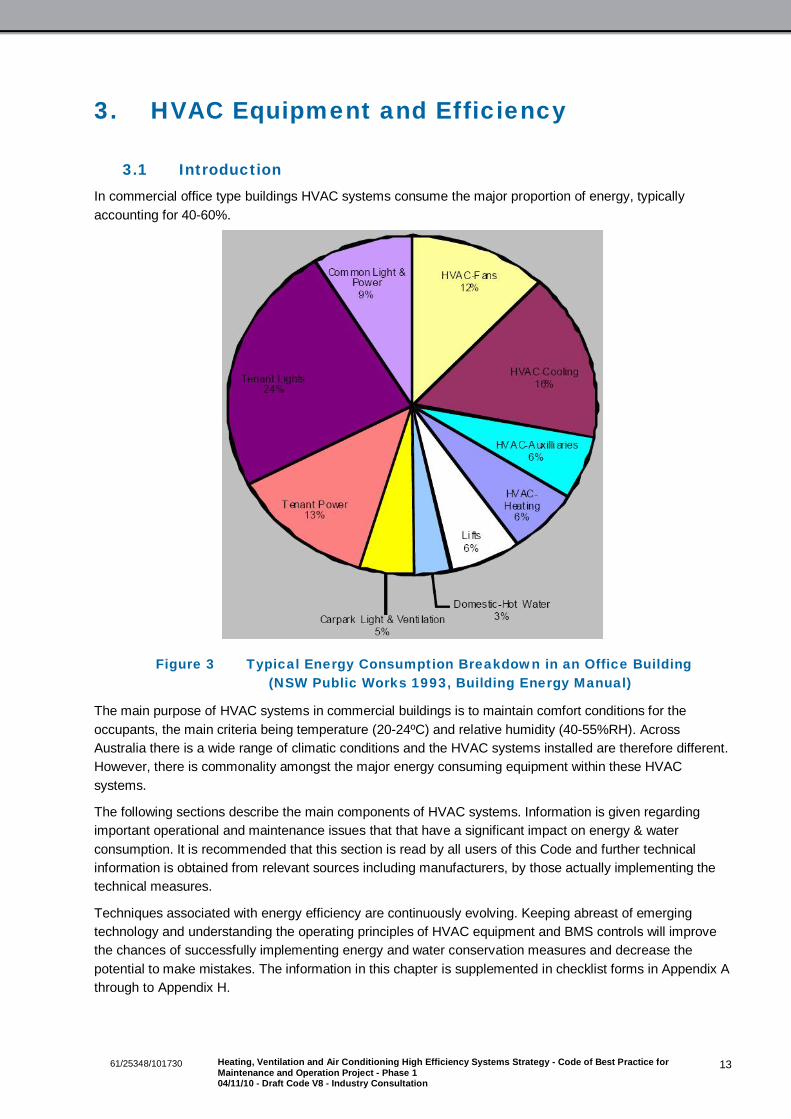
3.1 IntroductionIn commercial office type buildings HVAC systems consume the major proportion of energy, typicallyaccounting for 40-60%.
Figure 3 Typical Energy Consumption Breakdown in an Office Building(NSW Public Works 1993, Building Energy Manual)
The main purpose of HVAC systems in commercial buildings is to maintain comfort conditions for theoccupants, the main criteria being temperature (20-24ºC) and relative humidity (40-55%RH). AcrossAustralia there is a wide range of climatic conditions and the HVAC systems installed are therefore different.However, there is commonality amongst the major energy consuming equipment within these HVACsystems.
The following sections describe the main components of HVAC systems. Information is given regardingimportant operational and maintenance issues that that have a significant impact on energy & waterconsumption. It is recommended that this section is read by all users of this Code and further technicalinformation is obtained from relevant sources including manufacturers, by those actually implementing thetechnical measures.
Techniques associated with energy efficiency are continuously evolving. Keeping abreast of emergingtechnology and understanding the operating principles of HVAC equipment and BMS controls will improvethe chances of successfully implementing energy and water conservation measures and decrease thepotential to make mistakes. The information in this chapter is supplemented in checklist forms in Appendix Athrough to Appendix H.

1461/25348/101730 Heating, Ventilation and Air Conditioning High Efficiency Systems Strategy - Code of Best Practice forMaintenance and Operation Project - Phase 104/11/10 - Draft Code V8 - Industry Consultation
Further Information
1. CIBSE Guide- Energy Efficiency in Buildings: ISBN 0 900953 86 1.
2. Energy Efficiency Manual- Donald R Wulfinghoff: ISBN 0 9657926 7 6.
3. AIRAH Application Manual DA19: HVAC&R Maintenance: ISBN 0 949436 39 9
3.2 ChillersA chiller is a machine that produces chilled water that is used to air condition buildings. Chillers areexpensive items of plant and they consume significant amounts of energy in commercial buildings, thereforecorrect maintenance and operation is important.
Types of chillers in common use are:
Vapour Compression chillers- Commonly used type, these chillers use the vapour compression cycle forproducing chilled water. Electricity is consumed by the chiller compressor. These chillers can be furtherdescribed as air cooled chillers- where the chiller rejects heat to outside (ambient) air, or water cooledchillers- where the chiller rejects heat to water, typically from cooling towers.
Absorption chillers- these chillers use thermal energy (typically gas fired), rather than using electricity asthe main source of energy, to produce chilled water. Typical refrigerant (absorbent) used is LithiumBromide.
The efficiency of a chiller is measured in terms of its coefficient of performance (COP) or energy efficiencyratio (EER), both parameters stating the efficiency at full load conditions. Since chillers mostly operate atpart load conditions, the integrated part load value (IPLV) gives a more representative indication of chillerefficiency across typical loading factors encountered in buildings. Water cooled chillers which use coolingtowers are more energy efficient than air cooled chillers, however the costs associated with water and watertreatment need to be factored in. Modern chillers have high COPs compared to older chillers. The efficiencyof a chiller depends on the technology used in the chiller- for instance variable speed chillers and chillersthat use electromagnetic bearings have made a major impact on improving chiller efficiency. Another factorto consider is part load performance. A large chiller operating out of hours simply to serve a small load (suchas a lift motor room or a computer room) is likely to perform very inefficiently.
Absorption chillers have low COPs when compared to vapour compression types. However their majorenergy consumption is gas instead of electricity. This often has benefits in reducing the carbon footprint ofthe building and reducing electricity maximum demand charges. Absorption chillers can also operate using afree energy source such as waste heat from a gas fired engine/generator set that produces electricity.
Older chillers use CFCs (refrigerants that are banned from being manufactured or imported by the MontrealProtocol) and HCFCs (refrigerants being phased out). Therefore facilities managers may be faced with thepossibility of having to replace older chillers as existing stocks of CFCs and HCFCs run down.
Another recent option available is the availability of gas engine driven chillers and heat pumps, where anengine powered by gas drives a vapour compression type chiller.
Maintenance and Operation
Manufacturers’ guidelines and advice regarding maintenance must be followed. Also refer to AIRAHDA19.
Heat exchangers must be maintained in a clean state. Air cooled condensers must be cleaned regularlyand kept free from debris and possible restrictions including foliage. Water condensers must be cleanedat regular intervals and/or when evidence of fouling is noted through high temperature approach values.It is estimated that a build up of 0.6mm thickness layer of fouling on the condenser water tubes will
1561/25348/101730 Heating, Ventilation and Air Conditioning High Efficiency Systems Strategy - Code of Best Practice forMaintenance and Operation Project - Phase 104/11/10 - Draft Code V8 - Industry Consultation
reduce chiller efficiency by 20%. For larger chillers, the installation of automatic tube cleaning systemsmay be cost effective.
It is recommended that performance based maintenance is carried out on chillers, in addition toscheduled replacement of components as stated in manufacturers instructions. This relies on regularmeasurements of parameters including temperature and pressure drops through heat exchanges andmonitoring of chiller COP. This is ideally carried out on a continuous basis by a BMS, however wheresuch systems are not available, this may be achieved through regular recording of the data onmaintenance log books, by maintenance contractors.
Older chillers using reciprocating type compressors have thermostatic type expansion valves andreplacing these with electronic type expansion valves will deliver efficiencies in the order of 15-25%.
Check refrigerant charge and promptly repair leaks. Apart from environmental impacts including globalwarming and ozone depletion, the loss of refrigerant is expensive and will cause a reduction in plantcapacity and efficiency.
Check for water leaks from chillers and chilled water distribution system. Rectify leaks promptly.
The efficiency of a chiller can be enhanced by increasing the chilled water temperature and decreasingthe condenser water temperature within certain limits permitted by the chiller manufacturer. Typically a1ºC rise in chilled water temperature or a 1ºC lowering of condenser water temperature improves chillerefficiency by 3%. This method of chiller optimisation is called chilled water re-set or condenser water re-set and this method of chiller optimisation is possible for most buildings when suitable (mild) ambienttemperature conditions prevail.
Note 1: Consideration needs to be given to factors that might negate some of the efficiency gained atthe chiller. For instance raising the chilled water temperature will improve the chiller efficiency but moresupply air may be required from the air handling units to satisfy the building cooling load, therebyincreasing fan energy consumption at the AHU’s. Similarly, the extra energy necessary at the coolingtower fans to lower the condenser water temperature might negate the efficiency gains made at thechiller. There are well established smart control strategies (algorithms) which minimise the risk of these‘claw back’ effects negating energy efficiency initiatives and the facilities manager and the maintenancecontractor should seek expert assistance when considering major upgrades or smart controls.
Note 2: The chiller manufacturer must be consulted with regards to the maximum permissibleevaporating temperature and minimum acceptable condensing water temperature. Certain chillers areless tolerant of low condensing water temperatures. Eg older centrifugal types, reciprocating types thatuse thermostatic expansion valves and some screw types.
Optimise chiller sequencing strategy by operating the most efficient chiller to meet the prevailing coolingload. Inhibit chiller operation (chiller lock out) during low ambient temperatures when there is no demandfor chillers to operate and ensure that spurious cooling calls are minimised.
Ensure chiller control temperature sensors are calibrated and reading true, inaccurate readings will leadto inefficiencies or loss of capacity.
If large chillers, their associated pumps and other equipment such as cooling towers are being used toserve small after-hours loads such as lift motor rooms, security control rooms and server rooms, installdedicated supplementary systems to serve these areas after-hours rather than wastefully using centralchiller plant.
Replacing and Upgrading
The following points are given as indicators to consider chiller replacement and/or upgrade.
The chiller has refrigerants which have been phased out or are due to be phased out soon.
1661/25348/101730 Heating, Ventilation and Air Conditioning High Efficiency Systems Strategy - Code of Best Practice forMaintenance and Operation Project - Phase 104/11/10 - Draft Code V8 - Industry Consultation
Is more than 15 years old, spare parts are getting hard to source.
The chiller is proving to be unreliable or is due for a major (expensive) overhaul.
The cooling demand from the building has increased significantly.
The after hours load of the building is such that the chillers operate very in-efficiently.
If a chiller needs to be replaced, various factors must be considered. Simply replacing with a new machinesized for the same duty could result in lost opportunities for saving energy. Seek specialist advice andconsider the following factors:
Select chillers with high COPs and IPLVs.
Optimise chiller selection, don’t simply replace with the same capacity as the existing. The buildingcooling load may have changed over the years. Consider the demand cycle of the entire chiller systemand optimise the new chiller after investigating what its duty cycle would be. Seek advice if necessary,the potential financial and operational benefits from optimised chiller selection are significant.
Select a chiller that would be compatible with modern control strategies for saving energy and checkthat the chiller controls have the necessary communication interfaces such as BACnet or Modbus.Factors to consider are chilled water re-set, condenser water re-set, chiller load limiting capability andvariable chilled water flow.
Optimise chiller sequencing and controls strategy to operate the most efficient chiller to meet theprevailing cooling load. Implement energy smart strategies such as chilled water and condenser waterreset.
Install equipment for monitoring the chiller operation and efficiency. This information may be readilyavailable through the chiller controller or it may be necessary to install additional metering such as kWh,thermal energy metering or some additional temperature sensors connected to the BMS.
Consider implementing variable pumping of chilled water, to save energy. This measure is likely to beeffective where the chilled water has to be pumped over long distances or where there is significantthrottling of the primary chilled water flow.
Refrigerant Handling in HVAC Systems
The emission of all refrigerants from chillers and other HVAC equipment including packaged and split typesystems must be minimised. Apart from potential environmental harm from certain refrigerants and thedirect costs associated with replacement of refrigerant, indirect costs are incurred through lower efficiency ofthe equipment and possible impacts on NGERS reporting to a large facility.
It is illegal for refrigerants that have global warming or ozone depletion potential, to be vented to theatmosphere. It is irresponsible for persons including maintenance contractors and facility managers not tomake best endeavours to identify and to promptly rectify refrigerant leaks. It is a legal requirement fortradesmen working on refrigeration plant including chillers and air conditioning equipment to beappropriately licensed. The Australian Refrigeration Council Ltd. (ARC) is the body that manages theregulations under the Ozone Protection and Synthetic Greenhouse Gas Management Act (1989) and theARC provides the HVAC industry to comply with the law.
For systems where refrigerants are in use, measures must be taken to ensure that all maintenance activitiesincluding handling, storage and retrofitting of refrigerant are carried out in accordance with good practice,and this must be stipulated in contract conditions. For larger facilities the inclusion of a KPI that monitors theamount of refrigerant usage is essential. Refrigerant leakage monitoring systems are increasingly beingspecified together with liquid receivers large enough to store the system charge. For all facilities,maintenance log books must record the amount of refrigerant added to systems and contractors must bringto the attention of the Facility Manager any abnormal consumption.

1761/25348/101730 Heating, Ventilation and Air Conditioning High Efficiency Systems Strategy - Code of Best Practice forMaintenance and Operation Project - Phase 104/11/10 - Draft Code V8 - Industry Consultation
Further Information
1. HB40.1, The Australian Refrigeration and Air-conditioning Code of Good Practice - Reduction ofemissions of fluorocarbon refrigerants in commercial and industrial refrigeration and air-conditioningapplications ISBN: 0-7337-4170-3
2. Australia and New Zealand Refrigerant Handling COP 2007- DEWHA: ISBN 978 0 642 55379 3
3. The Australian Refrigeration Council Ltd. website www.arctic.org.
3.3 Cooling TowersCooling towers are used for the rejection of heat from chillers that are water cooled. Cooling towers drawheat rejection water (referred to as condenser water) from the chiller and this water is sprayed as dropletsthrough a stream of outside air drawn by a fan, evaporating a small proportion of the condenser water andcooling the remainder in the process. The outside air drawn through the cooling tower increases in humidityand temperature, and is discharged to outside.
A chiller is more efficient (performs with a higher COP) when it uses a cooling tower for heat rejection, ratherthan an air cooled condenser because the condensing temperature of the chiller can be much lower due tothe effects of evaporation of water. Water cooled chillers also last longer than air cooled chillers. A coolingtower can reduce the condenser water temperature down to typically 4ºC above the prevailing ambient wetbulb temperature. The difference in temperature between the water leaving the cooling tower and theambient wet bulb temperature is referred to as the cooling tower approach. The difference between waterentering temperature and water leaving temperature is known as the cooling tower range.
Systems that use water cooled chillers and cooling towers suffer the penalty of water consumption andcosts for water treatment to minimise risks of Legionella. Due to the costs associated with water treatment,the use of cooling towers is not cost effective for small chillers, typically below 600-800kW chiller capacity,unless they are part of a larger multi-chiller installation. The presence of a cooling tower in a buildingsignificantly lowers the energy consumption for air conditioning and significantly increases the waterconsumption, typically accounting for 30-40% of the total water consumption of the building.
Water is lost from a cooling tower, mainly due to evaporation, which is necessary for the tower to function.Water is also lost through drift and splash- which is the in-evitable loss of water droplets to the air streamand the surrounding area. A cooling tower also loses water through bleed- which is the intentional dischargeof water in order to reduce the concentration of solids (minerals and organic matter) in the water. Bleed istypically controlled by an automatic system which senses Total Dissolved Solids-TDS in the water within thecooling tower. The ratio between the TDS in the tower/TDS in the mains water supply is referred to as thecycle of concentration.
In a well maintained tower the water consumption is as follows:
Evaporation (88%): Drift & Splash (7%): Bleed: (5%).
A recent development is the use of adiabatic coolers which only consume water for evaporative coolingduring conditions of high ambient temperature. When used in suitable (dry) geographic regions, these havethe potential to give high energy efficiency with low water consumption and without the associated watertreatment costs.
Maintenance and Operation
Manufacturers’ guidelines and advice on maintenance specifications must be followed. Also refer toAIRAH DA 19 and DA17.
Ensure that there is no overflow of water from the basin due to:

1861/25348/101730 Heating, Ventilation and Air Conditioning High Efficiency Systems Strategy - Code of Best Practice forMaintenance and Operation Project - Phase 104/11/10 - Draft Code V8 - Industry Consultation
– Faulty water level controls.
– The volume of water within the high level return line, draining to the sump, when the tower stopsoperating.
– Where multiple towers are installed, a lack of a balance pipe to equalise water levels.
Water leaks from corroded pipes and valves must be eliminated.
Optimise the water bleed rate in accordance with the quality of the mains water, the water treatmentregime and the type of cooling tower. Where automatic TDS controls are installed, these must becalibrated and adjusted correctly. Where such controls do not exist, their installation would be beneficialbecause excessive water bleed loss due to the TDS setting being too low is wasteful. Operating coolingtowers with cycles of concentration typically below 3-5, indicates water wastage. Depending on thequality of the mains water, cycles of concentration as high as 8-9 may be possible.
The type and condition of splash guards and drift eliminators must be checked to ensure that waterwastage due to poor design and/or condition of the splash guards and drift eliminators is minimised.Replacement drift eliminators must comply with AS 4180 which limits the drift loss to 0.002% of themaximum design water circulation rate through the cooling tower. Chemicals and exposure to the suncould degrade these components over time.
The cooling tower fill must not be allowed to gather excessive fouling. Apart from the microbial hazards,excessive fouling on the fill material could also affect the break down of water flow and make the coolingtower less efficient by increasing the temperature approach of the tower.
The airflow around cooling towers must not be restricted. Discharge air from the cooling tower must notbe allowed to re-cycle into the intake. If prevailing winds are affecting the air flow through the coolingtower, it may be necessary to construct a wind barrier.
Where a cooling tower bypass valve is installed, there must be no conflict of controls between the valvebeing open and the fans being operated. Ensure that there is at least a 2ºC differential between the valveclosing and the fans operating.
The strategy for staging cooling towers and their fans must be optimised. Best efficiencies will be gainedwhen all available cooling towers are operated in parallel, rather than running the lead cooling tower tomaximum and staging the remainder. To obtain the best efficiency, fans should be speed controlled,rather than being switched on/off or operated on two speed. With an increasing demand for heatrejection from the chillers, initially each fan should be brought on line at the minimum permissible speed.Once all fans have been enabled, they should be modulated in unison.
Control algorithms must be programmed to minimise fan power consumed to deliver the desired condenserwater temperature to the chiller. Often, the set point for control of cooling tower fans is below the prevailingambient wet bulb temperature and this wastes energy because the fans are being asked to operate at100%, trying to deliver the impossible. This energy wastage can be minimised by staging the cooling towerfans to deliver condensing water temperatures which track the prevailing ambient wet bulb temperature by3-4ºC, depending on the capability of the tower. The controls strategies for optimising chiller efficiency andcooling tower efficiency must be considered together, to ensure that they don’t negate one another.
If a plate heat exchanger (PHE) is installed to protect equipment such as supplementary AC units connectedto an open circuit cooling tower, ensure that the pressure drop through the PHE is not excessive and thatthe system is not fouled. If the pressure drop is excessive, typically > 30kPa, then consider the addition ofmore plates to the PHE and re-balancing the water flow rate. Pumping energy can be saved by theinstallation of two port motorised valves at the supplementary AC units to shut down water flow when therefrigerant compressor is not in operation, thereby enabling the pump to be slowed down through VSDcontrol. Ideally this measure should be implemented at design stage of a fit out, or when supplementary ACunits are replaced, in order to avoid issues with nuisance tripping. However, if the systems are specified to

1961/25348/101730 Heating, Ventilation and Air Conditioning High Efficiency Systems Strategy - Code of Best Practice forMaintenance and Operation Project - Phase 104/11/10 - Draft Code V8 - Industry Consultation
incorporate the necessary time delays and control interlocks that ensure adequate water flow through theunits when the compressor is in operation, then this measure can be successfully retrofitted. It is alsoessential that this issue is covered under ‘tenancy rules’ to ensure that appropriate units are installed by thetenant.
It is essential for energy efficiency and water conservation that monitoring of cooling tower performanceis carried out, including the following:
– Water consumption, by installing dedicated water meters, preferably connected to the BMS. Alarmsto register if water is consumed after hours or exceeds pre-determined levels.
– For larger installations, the monitoring of cooling tower fan energy consumption, together withperformance indicators such as ambient wet bulb, condenser water flow temperature, VSD speed.
– Total dissolved solids (TDS) sensors, independent from the control sensor. Alarms to register if TDSis too low (too little bleed- risk of fouling the heat exchangers) or too high (water wastage).
Replacing and Upgrading
Replace with new fill material and drift eliminators that comply with AS 4180.
Consider the cost benefits of replacing cooling towers with adiabatic type coolers. These units are suitedfor dry climates. The capital cost of these units will be higher and they will require a larger footprint. Theoverall energy efficiency of the chilled water system will be lower, however, life cycle costs could belower due to the reduced water consumption and the elimination of water treatment costs associated withLegionella. For certain applications where the risks associated with Legionella have to be eliminated, thistype of system will give a definite advantage.
Using re-cycled water
The use of re-cycled water for cooling towers may be feasible and initially this must be discussed with awater treatment specialist. Using re-cycled rain water and condensate collected from the HVAC air handlingunits may be cost effective for saving water and costs associated with water treatment, because re-cycledwater is likely to contain less dissolved solids than mains water.
Further Information
1. AIRAH DA 17-Cooling Towers: ISBN 978 0 949436 46 7.
2. Sydney Water: Best Practice Guidelines for Cooling Towers in Commercial Buildings.www.sydneywater.com.au
3. Water Efficiency Guide- Department of the Environment and Heritage: ISBN 06425 52878
3.4 Air Handling Units & VAV Boxes
Air Handling Units
Air handling units (AHU’s) are used to condition and circulate air within buildings. AHU’s typically contain airfilters, a circulating fan, cooling coils and heating coils. The cooling coils have chilled water supplied fromthe chillers and the heating coils have heating hot water supplied from heat generators, typically referred toas boilers. Some AHU’s have electric heating elements to provide space heating. Sometimes AHU’s alsohave humidifiers installed (for increasing the humidity), although these are rare in office type buildings.
Depending on the type of HVAC system, AHU’s may either be constant air volume or variable air volume(VAV).
AHU’s supply a mixture of outside air and recirculated air to the occupied space, this mixing of air beingcarried out by modulating dampers within a mixing plenum. During early morning ‘warm up’ and ‘cool down’
2061/25348/101730 Heating, Ventilation and Air Conditioning High Efficiency Systems Strategy - Code of Best Practice forMaintenance and Operation Project - Phase 104/11/10 - Draft Code V8 - Industry Consultation
cycles, the outside air should be at 0% to minimise energy consumption. When suitable outside conditionsprevail (mild temperature and low humidity), the % of outside air can be increased to 100%, therebyreducing chiller operation and saving energy- this process is called the economy cycle. Operating AHU’sovernight, using low temperature ambient air to pre-cool buildings is called night purge. For certain types ofbuilding which have high thermal capacity, night purge can be an effective means of reducing daytime chilleroperation, hence energy consumption. However, care must be given to the controls strategy to ensure thatheating systems do not operate spuriously after night purge and to ensure that overnight fan energyconsumption does not exceed the benefits from cooling.
Poor control of airflow and temperature are a common cause for poor efficiency in AHU’s. Optimisation ofthe performance of an air distribution system depends on the proper interaction (coordination) between theAHU controls and the controls at zone level- such as VAV terminal devices.
VAV Boxes
VAV boxes (also known as VAV terminals) are devices that control the supply air flows into zones withinoccupied spaces. Each VAV box receives supply air from an AHU and a box serves a number of supply airdiffusers located within a zone in the occupied space. The zoning of occupied spaces, location of the VAVboxes, the type of supply air diffusers and factors such as the minimum & maximum air supply air flow ratesare designed by the design engineer. The Property Council of Australia - A Guide to Office Building Quality(www.propertyoz.com.au/) gives guidelines on the maximum size of zone to be served by one VAV box,smaller zone sizes reduce temperature variations within the zone (therefore enhance comfort) but increasescapital cost. During office fit outs, the design parameters for a zone are sometimes changed- factors suchas higher occupant densities, higher equipment loads, the installation of partitions and the location of officeequipment in a manner that affects zone temperature sensors all contribute to non performance of VAVboxes resulting in discomfort and/or energy wastage.
Each VAV box is controlled by a temperature sensor, the supply air volume being reduced as the zonetemperature reaches set point, a minimum supply air rate being maintained for ventilation purposes. OftenVAV terminals are installed with re-heat capability, being either electric or hot water. Reheat is requiredeither for heating perimeter zones and/or to maintain comfort conditions within the zones. Sometimes, evenwhen the supply air flow to a zone is throttled down to minimum, the cooling effect of the supply air issufficient to cause over cooling to the zone, hence re-heat must be used to maintain comfort conditions.Minimisation of re-heat is important towards making VAV systems efficient.
Modern VAV boxes are ‘pressure independent’ type, they can maintain the design air flow rates in spite ofvariations to supply air pressure. Some (older) types VAV boxes are fan assisted, the ‘series fan’ type has afan which operates continuously, the ‘parallel fan’ type has a fan that is operated when extra air flow isrequired for purposes such as space heating. Parallel fans can also be switched independently of the mainAHU for morning warm up of perimeter zones.
Poor setting up of design maximum/minimum air flows in VAV boxes, poor control strategies including a lackof coordination between the VAV boxes and the AHU that serves them, broken VAV boxes and leaking hotwater valves are collectively responsible for significant amounts of energy wastage in a typical office that isserved by VAV systems. The problems are often un-noticed because the heating system counteracts thecooling system and comfort conditions are maintained. Energy wastage is increased when zone set pointsare altered by operators in an attempt to ‘quick fix’ complaints of discomfort, without investigation of the rootcauses. Random alteration of zone set points can cause the relevant AHU to over cool the supply air to anextent which creates a significant re-heating demand at other zones and it is not a rare occurrence inbuildings for heating boilers to operate in the height of summer, fighting the cooling system, wasting gas andelectricity.
2161/25348/101730 Heating, Ventilation and Air Conditioning High Efficiency Systems Strategy - Code of Best Practice forMaintenance and Operation Project - Phase 104/11/10 - Draft Code V8 - Industry Consultation
Maintenance and Operation
Ensure heat exchange coils are kept clean. Dirty heat exchange surfaces (coils) increase resistance toheat transfer, thereby reducing chiller and boiler efficiency. Dirty coils also increase the resistance to airflow, the consequences of which are either an increase in fan energy consumption (where VSD’s areinstalled) or a reduction in airflow with possible discomfort and inadequate ventilation. The AIRAH bestpractice guidelines ‘HVAC Hygiene’ deals with maintaining HVAC systems with regards to reducingcontamination.
Replace or clean air filters regularly, in accordance with the maintenance schedules. Dirty air filters leadto an increased resistance to air flow and compound the effects mentioned above.
Check for leaking heating & cooling control valves, which have the potential to cause the heating systemto fight the cooling system. This is a common problem in buildings that is often unnoticed and wastes alot of energy.
Regularly inspect and eliminate all sources of air leakage through damaged flexible connections, poorductwork joints and access doors/panels.
Ensure that the economy cycle is set up correctly and functions satisfactorily. Common causes for in-efficiency include incorrect control algorithms, failed dampers & control actuators or failed temperatureand humidity sensors.
Avoid the installation of motors with poor efficiency- especially re-wound motors on large AHU’s. The lifecycle energy costs of a motor are significantly higher than the capital cost.
Rectify any misalignment between belts and pulleys, thereby minimising losses due to friction. For largemotors, typically greater than 20kW, investigate the feasibility of installing positive drive belts and toothedpulleys rather than V type belts, to reduce frictional losses.
Investigate whether AHU’s are performing active de-humidification or humidification, in order to maintainclose control of humidity- a feature not essential for most office type buildings. Either disable thesefunctions or operate the systems over a wide dead-band to reduce de-humidification and humidification.Buildings that have chilled beams will require active-dehumidification to outside air under certaincircumstances. Investigate the set points for excessive safety margins and check the calibration of thedew point sensors.
On constant air volume AHU’s, check whether the fan is oversized and there is excessive throttling ofairflow using dampers. The solution is to re-size the pulley ratio and to open the dampers.
Ensure that service lights inside AHU’s are not left continuously in operation. Light switches should haveindicator lights and maintenance contractors must be advised to switch these lights off. The facilitymanager should carry out random inspections to ensure that this is carried out.
Check the accuracy and location of zone temperature sensors. Common issues are poor sensorcalibration, air leakage into the sensor through poor gland sealing and sensors being affected by heatsources such as sunlight & office equipment (such as PCs). These faults can drive the zone AHU tosupply excessive cooling, heating or air flow, thereby wasting energy. Tenancy rules should address theissue of tenant’s equipment adversely affecting control sensors.
Ensure that tenancy fit outs have not affected airflows into the zones. Wall partitioning that disrupts airflow, excessive lengths of flexible ducting, often squashed and disconnected supply air diffusers,sometimes with supply air ducts that are open ended, are root causes for zone temperature controlfailure that drive AHU’s to perform inefficiently.
On VAV systems, check the following:
– The pressure control set point for the AHU supply air fan being set too high, or the sensor beingfaulty and the fan operating at constant speed without modulating, thereby wasting energy.

2261/25348/101730 Heating, Ventilation and Air Conditioning High Efficiency Systems Strategy - Code of Best Practice forMaintenance and Operation Project - Phase 104/11/10 - Draft Code V8 - Industry Consultation
– The AHU fan should be controlled on a critical zone re-set algorithm, which would ensure that theduct static pressure is dynamically reduced to ensure that at least some VAV boxes are fullyopened, and the duct static pressure is kept minimal.
– Variable pitch inlet guide vane mechanisms being faulty.
– Supply air temperature being set too high (wastes fan energy). Supply air temperature being too low(wastes energy for re-heating).
Check the operation of VAV boxes. Often there is at least one faulty VAV box on each floor or in eachzone. Apart from the discomfort and wasted energy at zone level, if the control algorithm is set to drivethe AHU based on the parameters sensed at the worst performing terminal, this could lead to massiveenergy wastage due to excessive cooling and wasteful reheating. Regular monitoring of the VAVterminals, prompt repairs and setting up smart control strategies will eliminate this energy wastage.
If monitoring indicates issues which are due to a lack of air balancing, then it will be advisable forsystems to be re-balanced and commissioned, at least on a floor by floor basis. Quite often FacilityManagers do not prioritise this important issue due to a lack of understanding of the problems and a lackof appreciation of the potential benefits. If a Maintenance Contractor can effectively target the systemdeficiencies through monitoring the BMS and make an effective business case for re-commissioning,then this work is more likely to gain approval to proceed, with benefits to both parties and possibly theoccupants as well, through enhanced comfort.
Check the minimum and maximum air flow settings on the VAV terminals. These are initially determinedby the design engineer, in accordance with the assumptions made at design stage. However, untiloccupants move in and the dynamic thermal characteristics of the building are actually determined, thereis no way of determining whether these values are optimal. If the minimum air-flow setting at a terminal istoo high, there could be wasteful re-heating at the terminal, and during shoulder seasons, this couldtrigger a heating call that operates the entire heating stem, thereby wasting significant amounts ofenergy. If the maximum airflow is too low, this could drive-down the supply air temperature of the AHU inorder to satisfy the cooling demand of this zone, and this in turn could cause wasteful re-heating at theother terminals. Often, design engineers are conservative with the specification of the minimum air flowsetting (the minimum setting is specified high), due to concerns with discomfort due to ‘dumping’ of coldair and compliance requirements of AS1668.2 with regards to minimum outside air requirements.Providing the minimum outside air requirements for the occupancy is met, it is often possible to set theminimum air flow rates to as low as 30% of design, for swirl type diffusers, without causing discomfortfrom ‘dumping’.
Regular monitoring of VAV terminals and the causes for heating and cooling calls will enable potentialissues that cause inefficiency to be identified. It may be necessary to engage the services of a controlsspecialist to set up the necessary smart control algorithms to avoid such issues.
Many buildings do not have the design air and water flows in operation. The reasons for this are that eitherthe HVAC systems were never commissioned and balanced initially or over the years or tenancy fit outshave been carried out with scant regard to air balance issues. Sometimes, tenancy fit outs change the zoneheating and cooling loads which have a bearing on the required air flow rates. The value of propercommissioning, fine tuning, re-balancing and retro-commissioning is now being realised. Often, the costs(and logistics) associated with fully retro commissioning a building prevents Facility Managers fromaddressing this important issue. Therefore it may be more cost effective and feasible for air and waterbalancing to be carried out during the tenure of a maintenance contract, at least on a staged basis- E.g.,floor by floor basis.

2361/25348/101730 Heating, Ventilation and Air Conditioning High Efficiency Systems Strategy - Code of Best Practice forMaintenance and Operation Project - Phase 104/11/10 - Draft Code V8 - Industry Consultation
Replacing and Upgrading
Don’t simply replace like with like. Ensure that the design air flow rates are re-assessed, withconsideration of factors including design heat losses & gains, which are likely to have changed since theoriginal design. Consider whether the design supply air temperatures are appropriate for energyefficiency, investigate potential benefits from a lower supply air temperature- lower air volume flow rates& lower fan energy verses higher chiller energy consumption.
Consider maximum use of the economy cycle, CO2 control of outside air and the installation of heatexchange between the supply & exhaust air streams.
Carefully select the fan for efficient operation. Install high efficiency motors and low loss belts & pulleys.The use of plug type fans (no belt and pulley losses) may be beneficial.
Do not re-wind motors, the higher energy costs of a re-wound motor is likely to outweigh savings incapital cost. It is recommended that a purchasing strategy is in place and maintenance contractors areinstructed accordingly, to ensure that replacement fans and motors are energy efficient. Replacement ofexisting fans also presents good opportunities to remedy existing problems such as throttling.
If the air supply diffusers are to be replaced as part of a major fit out, consider high efficiency swirl typediffusers which have high turn down ratios, which will reduce re-heat requirements significantly andreduce energy wastage.
Install duct static pressure sensors at appropriate locations, ensure efficient control strategies such ascritical zone re-set are in place to minimise fan energy consumption.
3.5 BoilersGas fired boilers are commonly used to provide heating hot water for air handling units in commercialbuildings. The term ‘boiler’ is the traditional name given. However, the term ‘hot water generator’ is morerepresentative. Most commercial buildings have boilers producing heating hot water at temperatures below85ºC and are referred to as low temperature hot water (LTHW) or low pressure hot water (LPHW) boilers.
Boilers are classified according to whether they are naturally aspirated (atmospheric) or forced draught, thelatter being more efficient and more compact. Modern boilers are much more efficient than older boilers dueto technological advances including pre-mix type burners, high efficiency fabricated heat exchangers andgood thermal insulation.
Condensing boilers are very efficient, with thermal efficiencies typically exceeding 96%- based on thegross calorific value. These boilers extract a very high percentage of energy from the combustion productsand therefore produce a plume of vapour in the exhaust. Condensing boilers have been successfully used inEuropean countries for the past 20 years and are in fact mandatory in many countries. For condensingboilers to be optimally efficient, the return water temperature to the boiler has to be below 55ºC, a fact toconsider when retrofitting these boilers. This could ideally be achieved by over-sizing the heat exchangersinitially or by specially designing the heating circuits. However these options are often not available whenretrofitting under maintenance contracts. Efficiency gains are also possible by scheduling the heating watertemperature to be high only during the relatively short periods for initial warm up and during extremely coldweather, the remainder of the time the flow temperature being low enough to cause condensing conditions.If condensing and conventional boilers are used in the same heating circuit, it is necessary to consider theeffects of low water temperatures on the conventional boilers, to prevent possible damage due to ‘back endcorrosion’ a term which describes corrosion that occurs in a conventional (non condensing type) boiler,when the return water temperature falls below 55ºC for prolonged periods.

2461/25348/101730 Heating, Ventilation and Air Conditioning High Efficiency Systems Strategy - Code of Best Practice forMaintenance and Operation Project - Phase 104/11/10 - Draft Code V8 - Industry Consultation
The efficiency of a boiler depends very much on the cleanliness of its heat exchangers and the state oftuning of the fuel/air ratio at the burner. To obtain optimal efficiency, combustion analysis must be carriedout on larger boilers at least once a year and the air/fuel ratio adjusted for optimal efficiency.
Maintenance and Operation
Manufacturers’ guidelines and advice on maintenance specifications must be followed. Also refer toAIRAH DA19.
Periodically (at least once a year) carry out combustion analysis and tuning of air/fuel ration to optimisecombustion efficiency for the range of output that is most applicable to the boiler, which may notnecessarily be 100%.
Ensure water treatment (corrosion inhibition and scale prevention) is satisfactory and water leaks fromthe heating system are eliminated. Make up water introduces oxygen and dissolved solids into thesystem which could lead to corrosion and/or scaling of heat exchanges and a loss of efficiency.
Check for water leaks from boilers and heating water distribution system. Rectify leaks promptly.
Check for damaged thermal insulation in heating water distribution system. Repair where necessary. Forsystem components such as heat exchangers, valves, strainers and flanges, it is unlikely that retrofittingproprietary thermal insulation to a high standard (that looks good), will be cost effective. However, theinstallation of 50mm silver foil lined glass wool, held in place with chicken mesh and wire will perform aswell and cost much less.
Poor boiler controls can contribute significantly to inefficiency. Spurious heating calls can lead to highheat losses due to short cycling, standby and pre-purge losses. Ensure that secondary means of controlare in place to minimise these issues- outside temperature lockouts and heating call verification (whichprevents boiler operation due to faulty control valves) are recommended.
Boiler sequencing controls should ensure that the most efficient boiler is matched to load demands. Thehot water flow temperature should be minimised to improve boiler efficiency (especially on condensingboilers) and to reduce heat losses from pipe-work. Note: for conventional boilers, to prevent internalcorrosion, ensure that the return water temperature is above the acid dew point- which is the temperatureat which the flue products condense.
Where multiple boilers are installed, especially atmospheric types (which have high standby heat lossesdue to natural convection), ensure that water flow does not occur through boilers not in use. This may beachieved through manual shut down of boilers (with due consideration of redundancy), through theinstallation of motorised valves or the installation of motorised flue dampers.
Replacing and Upgrading
Do not replace like with like. Re-asses the heat load of the building and select boilers that would deliver agood match between system demand and boiler capacity.
Consider the installation of high efficiency boilers including condensing boilers- at least as the lead boiler.
For systems that have high distribution pressure losses (typically on systems that have very longdistribution runs), consider converting the heating system to primary/secondary, in order to reducepumping energy.
3.6 PumpsPumps are used in HVAC systems, mainly for the circulation of water, which is used as a medium for heattransfer between chillers, boilers, air handling units and other heat exchangers. The correct selection of apump and its drive motor is important for energy efficiency. BCA Section J stipulates the maximum
2561/25348/101730 Heating, Ventilation and Air Conditioning High Efficiency Systems Strategy - Code of Best Practice forMaintenance and Operation Project - Phase 104/11/10 - Draft Code V8 - Industry Consultation
permitted power consumption for a particular duty. It is accepted that under most maintenance contracts,replacement of pumps may have to be carried out on a like for like basis to expedite replacement of animportant piece of equipment.
Apart from their impact on energy consumption, pumps also have the potential to affect the water (andenergy) consumption if they leak. Commonly used types of pump have gland-type seals and these arepotential sources of water leakage. Regular inspections are required to ensure that water leaks are repairedpromptly.
Maintenance and Operation
Routinely check for water leaks in accordance with maintenance schedules. Also refer to AIRAH DA19.
Ensure that all non essential pumps are automatically switched off when the circuits they serve are not inoperation.
Ensure that there is no unnecessary throttling of system water flow at balancing valves or isolation valvesin the index circuit (the circuit with the highest pressure drop). For constant volume pumping systems,opening the valves on the index circuit and either replacing the impellor, trimming it or the installation of aVSD will deliver energy savings. The longer the hours of operation are and bigger the size of pump, thehigher the cost benefit of this measure would be.
If chilled water or heating hot water circuits are served by three port valves (i.e. the circuits are constantwater flow systems), investigate the feasibility of shutting down the bypass circuit at each valve andeffectively operating them as two port valves, thereby converting the circuit into a variable volumesystem. Energy will be saved if the pump is controlled by a VSD to maintain the design static pressure.The cost effectiveness of this system will depend on the size of system, the operating hours and theextent of tolerance of the chiller or boiler to variable water flows.
Note: Consideration needs to be given to the minimum water flow rate that has to be maintained throughthe chiller or boiler that the pump serves.
Replacing and Upgrading
Do not replace like for like. Investigate the feasibility of improving energy efficiency through options suchas converting constant volume pumping to variable volume pumping systems, seek assistance from aservices design consultant where necessary.
Do not re-wind motors, the higher energy costs of a re-wound motor is likely to outweigh savings incapital cost. It is recommended that a purchasing strategy is in place and maintenance contractors areinstructed accordingly, to ensure that replacement pumps and motors are energy efficient. Replacementof existing pumps also present good opportunities to remedy existing problems such as throttling.
3.7 FansFans installed within AHU’s are covered in the Air Handling Unit & VAV Boxes section. Fans are alsoinstalled for the purposes of conveying return air from occupied spaces to AHU’s and for purposes ofextraction from areas such as toilets. Specialist fan systems such those installed for fire protection,consume insignificant amounts of energy, hence are not covered in this Code.
The main factors for saving energy from fans include the specification of efficient fans & motors, ensuringfans are switched off when not required and reducing the fan duty when possible through the use of VSDs.Car park ventilation systems are a good example where significant energy savings can be made through theinstallation of VSDs.
2661/25348/101730 Heating, Ventilation and Air Conditioning High Efficiency Systems Strategy - Code of Best Practice forMaintenance and Operation Project - Phase 104/11/10 - Draft Code V8 - Industry Consultation
Maintenance and Operation
Ensure that all non essential fans are automatically switched off when the systems they serve are not inoperation.
Ensure that belts and pulleys are aligned correctly, misalignment increases friction and wastes energy.
Ensure that there is no unnecessary throttling of system air flow at balancing dampers in the index circuit(the circuit with the highest pressure drop). For constant air volume systems, opening the dampers onthe index and other circuits and either replacing the belts & pulleys to reduce the fan speed, replacing thefan with one that delivers less air flow or the installation of a VSD will deliver energy savings. The longerthe hours of operation are and bigger the size of fan, the higher the cost benefit of this measure wouldbe.
Replacing and Upgrading
Do not replace like for like. Investigate the feasibility of improving energy efficiency through options suchas converting constant volume pumping to variable volume pumping systems, seek assistance from aservices design consultant where necessary. The installation of motorised dampers in tenant’ssupplementary supply air systems and extract systems is recommended, with dampers shutting offautomatically when the connected equipment is not in operation. The fan can be controlled via a VSD toreduce energy consumption.Ensure that these issues are covered in tenancy rules, where tenant installed equipment must complywith these requirements and incorporate the necessary control interfaces.
Convert car park ventilation systems from constant air volume to variable air volume systems bycontrolling the fans through VSDs controlled by carbon monoxide (CO) detectors, in accordance withAS1668.2. The cost benefits from this will depend on the size of car park, bigger the area, better the costbenefits.
Do not re-wind motors, the higher energy costs of a re-wound motor is likely to outweigh savings in capitalcost. It is recommended that a purchasing strategy is in place and maintenance contractors are instructedaccordingly, to ensure that replacement fans and motors are energy efficient. Replacement of existing fansalso present good opportunities to remedy existing problems such as throttling.
3.8 Humidification and De-HumidificationHumidifiers are used to increase the level of humidity within buildings, typically under conditions whereoutside air needs heating during colder (winter) periods. Heating outside air, lowers its relative humidity(RH) and could cause excessively dry conditions inside the occupied spaces. If RH typically falls below 35%for prolonged periods, the occupants could suffer from the effects runny noses (due to irritation caused tomucus membranes) and static electricity (electric shocks as objects such as office furniture and door knobsare touched). With improved carpet technologies, the latter problem has been alleviated to a large extent.
Humidifiers are not typically required in office type buildings, problems due to the effects of low humidity areusually cased by excessive use of outside air, either through over-conservative design or faulty economycycles. Where humidifiers have been installed, unless due consideration is given to their need andoperation, they could be wasting a lot of energy. Humidifiers used in offices are typically of the electrodeboiler type; therefore the energy they use is electricity which has a high green house coefficient and thepotential to add considerably to maximum demand charges.
Apart from electrode boiler types, ultrasonic type of humidifiers may also be in use. Although these consumeless electricity for the humidification process, the HVAC system will still require thermal energy (from boilersor electric heaters) to re-heat the supply air, due to the cooling effect of the water evaporated from theultrasonic humidifier.

2761/25348/101730 Heating, Ventilation and Air Conditioning High Efficiency Systems Strategy - Code of Best Practice forMaintenance and Operation Project - Phase 104/11/10 - Draft Code V8 - Industry Consultation
Active de-humidification is rarely required in commercial offices; occupants can typically tolerate high RHlevels of around 60-65% for short periods, providing the prevailing space temperature is low enough tomaintain space conditions within accepted human comfort zones. The important exception to this arebuildings which have chilled beam technology installed, if the internal space humidity conditions are allowedto rise, moisture could form on the chilled beams and ‘rain down’ on occupants. Active de-humidificationtypically uses chilled water to over-cool the supply air (thereby condensing moisture out) and then re-heating using the space heating system. HVAC systems in commercial offices typically incorporate a morepassive means for de-humidification in summer; the cooling coil removes some of the moisture from the airas it lowers the temperature.
Facilities managers should be aware (or made aware by maintenance contractors) of humidifiers and activede-humidification that are in operation in buildings.
Maintenance and Operation
Carry out assessment whether humidification and active de-humidification are in operation. Evaluatewhether their operation is necessary, giving consideration to any service level agreements that stipulateclose control of humidity. For typical offices, providing the HVAC systems are designed and operatedcorrectly, there should be no requirement for humidification (or active dehumidification) and where suchsystems are in use, this should be negotiated with the building occupiers and humidifiers should beturned off or their operating range limited. As a minimum, the operation of such equipment should berestricted during periods of maximum demand, this could make a significant impact to a buildingsmaximum demand charges for electricity.
Ensure calibration of humidity sensors inside the building and the temperature and humidity sensors thatoperate the economy cycle. If the sensors are not reading true, this could possible lead to wastage ofenergy.
Programme the BMS to make maximum use of the economy cycle, optimising the use of outside air forpurposes of space cooling, de-humidification and humidification, as well as for ventilation. This level ofprogramming is not typically found in office buildings, however with careful setting up of the controlalgorithms and subsequent fine-tuning, it should be possible to achieve savings.
If the operation of humidifiers and active de-humidification is essential, it is important to monitor theirusage, through either the BMS, hours run counters and/or dedicated energy meters.
Where humidification and de-humidification are essential, it is important that the building or the space iswell sealed, with leakage of outside air minimised. A typical example being computer rooms.
Replacing and Upgrading
Design –out these systems where possible.
If necessary, reduce their operation to a minimum, use the economy cycle as much as possible.
Consider alternative technology such as desiccant dehumidifiers for energy efficiency.
Consider the use of heat (and moisture) exchangers.
3.9 Packaged HVAC SystemsPackaged HVAC systems, split type AC systems and AC systems that reject heat to a common condenserwater loop are likely to be installed in office type buildings, to serve certain areas. Such areas include liftmotor rooms (which need cooling after the main HVAC plant has shut down), security and other office areasthat operate continuously and tenant supplementary AC units installed to serve areas that have high coolingloads which cannot be serviced by the base building HVAC system. It would be rare to find such HVAC

2861/25348/101730 Heating, Ventilation and Air Conditioning High Efficiency Systems Strategy - Code of Best Practice forMaintenance and Operation Project - Phase 104/11/10 - Draft Code V8 - Industry Consultation
systems serving large commercial office areas, except perhaps variable refrigerant volume (VRV) typesystems being installed to serve offices, instead of chillers, boilers and air handling units.
Tenant’s supplementary HVAC equipment is powered by the tenant’s distribution board, and this equipmentis usually maintained by the tenant. Inefficiencies associated with the operation of such equipment areborne by the tenant. The base building also can suffer (high energy costs and discomfort) when thesupplementary HVAC systems counteract the central HVAC plant and also when these systems depend oncentral plant for their operation, examples being condenser water supplied by the central plant andtempered outside air supplied by central plant.
Maintenance and Operation
Ensure systems are serviced in accordance with manufacturer’s instructions, at least annually. Heatexchangers must be cleaned. The refrigerant charge must be checked and topped up if necessary. Theoperation of controls must be checked, including the expansion device and superheat. Also refer toAIRAH DA19.
On VRV systems, maintenance is especially important. These systems are specialist in nature, ensurethat the service technicians are trained by the manufacturer of the system and they have the diagnosticsoftware and tools recommended by the manufacturer.
Minimise the operation of individual units, based on time and temperature. Is it really necessary tomaintain a lift motor room at 20ºC, when a temperature of 27ºC (or possible higher) is sufficient to keeplift maintenance technicians comfortable during routine maintenance visits, which are typically of shortduration. The facility manager can reduce the set point for occasions when the service technicians spendlong hours, or the set point can be lowered temporarily by pressing a self-timer. Similarly, question theneed to operate computer rooms such as server rooms at 20ºC, current thinking is that computerequipment can reliably operate at much higher temperatures of around 25-27ºC.
Lock the control thermostats in the desired position and/or label them accordingly.
Where supplementary HVAC systems are connected to BMS, ensure that the systems have controlinterlocks to prevent the supplementary HVAC system fighting the central system.
Install automatic controls to shut down supplementary HVAC systems automatically. These can take theform of self timers (typically set for 2 hours duration) or occupancy sensors. Ensure systems are labelledaccordingly.
For rooms such as lift motor rooms and computer rooms, ensure that the space is well sealed (except forthe provision of minimum outside air), shielded from solar gains. Install self closers on doors and/or ‘keepshut’ signs.
Replacing and Upgrading
Ensure systems have high efficiencies (or coefficients of performance COP)- systems must comply withcurrent minimum efficiency performance standards (MEPS) refer towww.energyrating.gov.au/meps1.html
For tenants’ supplementary systems, that depend on base building systems such as condenser waterand tempered fresh air, ensure that motorised valves & dampers are installed to shut down demandwhen the systems are not in use. When the refrigeration compressor is not in operation, the condenserwater valve should shut down. When the supplementary HVAC system is switched off, the tempered airdamper should shut down. This will enable central plant to be modulated, thereby saving energy. Ensurethat these issues are covered in tenancy rules, where tenant installed equipment must comply with theserequirements and incorporate the necessary control interfaces.

2961/25348/101730 Heating, Ventilation and Air Conditioning High Efficiency Systems Strategy - Code of Best Practice forMaintenance and Operation Project - Phase 104/11/10 - Draft Code V8 - Industry Consultation
Ensure systems operate only when required, incorporating automatic controls where possible. Whenordering new AC units, ensure that the necessary interface card is specified, to enable interfacing withexternal controls such as occupancy sensors or manually operated self timers.
3.10 Power Factor CorrectionMechanical services tend to have the biggest impact on the power factor in commercial buildings. Also, it ishighly desirable for power factor correction (PFC) equipment to be monitored, a function typically carried outby the BMS. Therefore, this topic is addressed in this code, although PFC equipment is not classed asHVAC systems.
Where a facility has a maximum demand component in the electricity invoice, it is essential to install PFCequipment. This basically consists of banks of capacitors which are automatically switched (by a PFCcontroller) according to prevailing electrical load conditions. Apart from reducing maximum demand chargesimproving the power factor at the mechanical services switch board will also enhance the capacity of thesub main cable, the main switch board and the supply transformer. It must be noted that the installation ofPFC correction equipment will only improve the power factor upstream of the point of installation.
Where PFC equipment is installed, the target power factor should be around 0.98-0.99 coincident with theoccurrence of maximum demand. If the corresponding power factor is less than 0.95, it is likely to be costeffective to investigate the causes and to improve the power factor- typically by replacing faulty capacitors,upgrading the existing capacitors or the installation of additional capacitors.
The installation of monitoring systems to PFC equipment is essential, because if failures are not remediedpromptly, the ensuing maximum demand charges could be significant.
Maintenance and Operation
Regularly monitor the systems for correct operation, especially during times of maximum demand.
Set up automatic alarm functions to warn of faults and loss of control. Use independent system (separatefrom a fault signal available from the PFC controller) connected to BMS, to monitor the power factor,certain electricity authorities permit direct connection of the BMS to the utility meter.
Rectify faults promptly.
3.11 Building Management SystemsBuilding Management Systems (BMS) control and monitor the operation of HVAC systems in buildings. Intypical buildings, BMS have the highest potential to deliver cost effective savings and improve systemefficiencies through the use of smart controls strategies to improve HVAC system performance. Additionalbenefits include monitoring of key performance indicators (KPIs) and providing timely warning when HVACequipment does not deliver the rated performance and systems don’t perform efficiently. The BMS can bethe most useful tool for all stakeholders to verify the performance of systems and service delivery by themaintenance providers.
Energy auditors can use information set up as trend logs or graphs on the BMS to monitor energyconsumption and diagnose abnormal performance. Facility managers can use BMS data for on-chargingtenants for after-hours usage of HVAC systems and for allocating costs. Maintenance providers can useBMS for monitoring certain parameters and KPIs for the purposes of condition based maintenance therebyreducing maintenance costs without compromising system performance or reliability.
Energy & water consumption can continuously be monitored by BMS and the system can either alarm oreven take corrective action should certain parameters be exceeded. An example being the shutting down ofa solenoid operated water supply valve that services non-essential equipment such as irrigation systems,

3061/25348/101730 Heating, Ventilation and Air Conditioning High Efficiency Systems Strategy - Code of Best Practice forMaintenance and Operation Project - Phase 104/11/10 - Draft Code V8 - Industry Consultation
should a pattern of water consumption indicate a possible leak. Also possible is load shedding or loadlimiting. At times of maximum demand the operation of equipment such as chillers and electrode humidifierscan be curtailed.
Unfortunately, in many buildings, the full potential of BMS systems is not used. BMS are often set up andcommissioned poorly at the tail end of projects. Operators are not trained adequately hence are not familiarwith the functions- some of which can be quite complex. Documentation is not updated to keep up withchanges made to the systems and trend logs are not set up for key parameters to identify non performance.Control loops are very rarely optimised for efficiency and the systems continue to perform on defaultsettings. The combined effects of these issues to a Facilities Manager and Maintenance Contractor is that itmay take a considerable amount of effort and specialist knowledge from a BMS specialist contractor, to getthe system to deliver optimal comfort and energy performance. A contractor tendering for a maintenancecontract that has specified deliverables for maintaining performance ratings or enhancing efficiency wouldbe well advised to obtain first hand knowledge about the state of the existing BMS.
For a BMS to deliver its full potential for optimising energy consumption, the systems have to be correctlyspecified, installed, commissioned & tuned. Continuous monitoring, maintenance including calibration ofsensors and fine tuning are required by skilled contractors to ensure that BMS continue to perform optimally.Sometimes BMS are underused and neglected to an extent where they perform little more than time clockfunctions.
Maintenance and Operation
The Facility Manager and Maintenance Contractor must familiarise with the capabilities and operationalparameters of the BMS. If necessary, the services of a BMS specialist will be required to updateavailable information on O&M manuals, including producing a functional description for the controlalgorithms.
It is important for maintenance contractors to have access to the BMS, for HVAC system maintenanceand operational purposes. The protocols and procedures for making changes to the BMS anddocumentation of any changes will need to be agreed between the Facility Manager and the HVACMaintenance Contractor. It is essential for key members in the Maintenance Contractors team to have agood working knowledge of the BMS operation, monitoring and targeting functions. The HVACMaintenance Contractor must allow to engage a specialist BMS contractor for services such asoptimisation of control algorithms, re- programming, setting up reporting functions (such as for NABERS)and diagnostic screens.
It is essential that diagnostic screens are set up for the verification of key HVAC system functionsincluding the economy cycle, operation of VAV boxes, modulation of fans & pumps through VSDs, chiller& boiler operation including flow temperature re-set and leaking valves.
Ensure HVAC equipment is correctly scheduled to operate only when required. Public holidays must beprogrammed. Optimum start and stop functions must be programmed where appropriate. After hoursoperation must be restricted only to enable the zones calling for HVAC.
For main energy consuming plant such as chillers and boilers, programme the BMS to give secondary oroverriding means of control (a belt & braces approach) to limit spurious operation. Examples are outsideair temperature lock outs for boilers, re-heat systems and chillers.
Ensure sensors are calibrated, at least annually. Ensure sensors are not affected by extraneous factorsincluding solar gains, heat output from office equipment, air leakage through unsealed cable entries.
Replacing and Upgrading
Do not replace like for like, simply replacing an existing BMS with new hardware and graphics, some ofthe controls algorithms residing within the existing BMS are likely to be inefficient. It is essential that a

3161/25348/101730 Heating, Ventilation and Air Conditioning High Efficiency Systems Strategy - Code of Best Practice forMaintenance and Operation Project - Phase 104/11/10 - Draft Code V8 - Industry Consultation
holistic view is adopted with a proper specification developed for the replacement BMS. Specifying a newBMS requires an in-depth knowledge and is much more complicated than specifying equipment such asa chiller, for which performance requirements can be easily stipulated in accordance with internationallyaccepted standards.
When producing a specification for a new system, all stakeholders must work as a team and carefullyevaluate the needs of the building, particularly the HVAC systems. The operational requirements andfunctions for monitoring key parameters & KPIs for performance based maintenance must beconsidered. Many energy smart control strategies have been developed recently and these mustevaluated against the HVAC systems in the building and specified accordingly.
Graphics, reporting pages for performance rating systems including NABERS and tools that enable easydiagnosis of non performance must be specified.
Ensure that proper commissioning and verification of BMS performance is specified. Also important ismonitoring and fine tuning over a 12 month period as well as training, technical support from establishedlocally based service technicians and on line assistance.
Further Information
1. CIBSE Guide H- Building Control Systems: ISBN 07506 504 78.
3.12 Commissioning, Tuning and Retro CommissioningEquipment such as chillers, boilers and air handling units only operate at design (worst case and deliveringmaximum output) conditions for very short periods in the year. Systematic and thorough commissioning ofHVAC and their control systems must be carried out after installation and testing of new equipment.Depending on factors such as the time of year (which determines outside air temperatures) and the level ofoccupancy in the building, the initial commissioning may have to be carried out during conditions which areeither simulated or non representative. For HVAC systems to deliver their maximum performance andenergy efficiency, it is important for fine tuning and re-commissioning of these systems to be carried outunder part load performance, and under representative conditions where different systems interact witheach other. e.g. The supply air fan in an AHU might deliver the design m3/s performance, but under realconditions where the VAV boxes throttle down, if the fan does not modulate satisfactorily, this is likely tolead to energy wastage and/or discomfort. Commissioning of HVAC systems and controls is an area whichhas traditionally been neglected due to a lack of awareness, prioritisation and competencies, with majorconsequences of energy wastage.
Green Star requirements have highlighted the importance of commissioning. The industry is now moreaware of the necessary resources including adequate planning & programming, trained commissioningtechnicians who are familiar with standards, proper equipment and the documentation which are allessential for a good outcome. At present, reference is made to CIBSE and ASHRAE commissioning guides,however AIRAH are currently in the process of developing a commissioning guide for use in Australia.
Building tuning should be carried out during the defects liability period, together with monitoring of thesystems and tracking the design environmental performance ratings of the building.
Retuning is carried out for older buildings, which have been in operation for a number of years. Retuning ofHVAC systems will probably be one of the most cost effective methods for improving energy performance intypical buildings. Retuning essentially identifies wasteful operational practices (such as ad hoc adjustment ofcontrol set points) and control inadequacies (such as poor sensor calibration, faulty field items includingmotorised dampers & valves) and corrects them. Re-tuning also covers the implementation of “smart” BMScontrols strategies, which may not have been implemented in the original system.

3261/25348/101730 Heating, Ventilation and Air Conditioning High Efficiency Systems Strategy - Code of Best Practice forMaintenance and Operation Project - Phase 104/11/10 - Draft Code V8 - Industry Consultation
Since retuning mostly involves interrogation and programming of the BMS, this is generally an inexpensiveand non-disruptive process. Retuning also identifies whether retro-commissioning is required and if so,identifies the areas that require this. e.g. whether air side or water side commissioning is required, whetheran entire building needs to be recommissioned or whether problems exist only in certain floors.
The term “retro commissioning” refers to recommissioning of existing buildings, often taking into accountchanges to heating and cooling loads that may have occurred over the years. Tenancy fit outs may alsohave affected the air and water side balance of the HVAC systems together with ad-hoc attempts to fixproblems by altering the settings on balancing valves and dampers.
Maintenance and Operation
Ensure that commissioning data is available for HVAC systems, together with details about operationand system drawings showing location of key system components including balancing valves anddampers. This information is typically available in operating and maintenance manuals.
Through regular monitoring of systems through the BMS (as described in the previous section) check forevidence that the air side and water side balance of the system is satisfactory.
If balancing is suspect, carry out checks using the services of a commissioning specialist and determinethe extent of the problem and determine whether re-commissioning a sub circuit, a floor or a zone islikely to remedy the fault or whether more extensive commissioning is required.
Carry out retro commissioning when required. If financial constraints prevent total systemrecommissioning, at least carry out a partial recommissioning on a staged basis- floor by floor or circuitby circuit.
Replacing and Upgrading
When upgrading HVAC systems, this is an ideal opportunity to asses the degree of commissioning andretuning of systems as necessary. Even if one major component such as a chiller is replaced, it isbeneficial to assess the water flows within the systems it operates, including chilled water andcondenser water flow rates.
It is essential for design engineers to include detailed commissioning specifications in tenderdocumentation. For new projects where Green Star requirements apply, the services of an independentcommissioning agent (ICA) are essential along with tuning. For larger HVAC upgrade projects, theservices of an ICA may be beneficial, together with commissioning plans and tuning during the defectsperiod.
Allow adequate resources and time for commissioning and the production of documentation. Resistpressure to reduce time allocated for commissioning due to time overruns during earlier stages ofprojects.

3361/25348/101730 Heating, Ventilation and Air Conditioning High Efficiency Systems Strategy - Code of Best Practice forMaintenance and Operation Project - Phase 104/11/10 - Draft Code V8 - Industry Consultation
Figure 4 Steps to Maintenance Implementation

3461/25348/101730 Heating, Ventilation and Air Conditioning High Efficiency Systems Strategy - Code of Best Practice forMaintenance and Operation Project - Phase 104/11/10 - Draft Code V8 - Industry Consultation
The subject of setting up and managing operating & maintenance contracts for facilities, includingcompliance with statutory regulations is comprehensively covered in publications which are well acceptedand readily available. This section of the Code describes important factors specific to energy and waterefficiencies, which must be given consideration when setting up maintenance contracts targeted to deliverenergy & water savings.
For buildings that are covered by existing maintenance contracts, it is important for Facility Managers andService Providers to give consideration to measures recommended in this section, which are likely to deliver‘win-win’ situations to the Client and the Maintenance Contractor by saving energy & water consumption.Priority must be given to issues such as setting up an asset register (if none exists or if the available registeris incomplete), comparing the current performance with available benchmarks, identifying potential KPIs andthe installation of electricity/gas/water sub metering that would be beneficial to monitor and improve theperformance of the existing contract and to gather the necessary data for setting up future ‘efficient’contracts. Under existing maintenance contracts, it may be feasible to cost effectively implement many ofthe recommendations in this section, and the key message is for Facility Managers to initiate discussions onthe topic of saving energy and water, with Maintenance Contractors. Opportunities will be lost if FacilityManagers and Maintenance Contractors simply turn a blind eye to potential efficiency measures, waiting forexisting contracts to run through.
The important factors that promote energy and water efficiency gains in HVAC maintenance and operationcontracts are as detailed in the paragraphs that follow.
In addition to assist stakeholders there are checklists available in Appendices A to H to assist in the HVACenergy efficient maintenance implementation.
Further Information
1. AIRAH application manual DA19- HVAC&R Maintenance:
2. CIBSE Guide M- Maintenance Engineering and Management: ISBN 978 1 903287 93 4.
3. CIBSE Guide to Ownership, Operation and Maintenance of Building Services: ISBN 1 903287 05 7
3.13 Develop Policies and Obtain Corporate Support
Environmental Policy
An environmental policy is a corporate document which states an organisations aspirations with regards toenvironmental responsibility covering sustainability aspects including Energy, Water, Waste Managementand Transport. The Building Owner is responsible for developing the Environmental Policy that applies to abuilding.
An environmental policy would typically include the following information:
An organisations mission statement with regards to safeguarding the environment.
Clear objectives with regards to achieving energy & water efficiencies. Environmental targets and goalssuch as NABERS ratings, renewable energy and goals to be carbon neutral.
Timeframe for achieving target goals.
Mechanism for monitoring and reporting.
Definition of roles and responsibilities for key stakeholders with clear objectives.
It is important for all stakeholders involved in the maintenance of HVAC systems to have writtenenvironmental policies which align with those of the building owner. Building owners and facility managers

3561/25348/101730 Heating, Ventilation and Air Conditioning High Efficiency Systems Strategy - Code of Best Practice forMaintenance and Operation Project - Phase 104/11/10 - Draft Code V8 - Industry Consultation
should ask prospective maintenance contractors for a copy of their environmental policy when requestingtenders for maintenance contracts.
For efficient operation and maintenance of HVAC systems, it is important for the relevant objectives in theenvironmental policy to be integrated with the maintenance policy.
Further Information:
1. AS/NZS ISO 14004: Environmental management systems -General guidelines on principles andsupporting techniques.
Maintenance Policy
A maintenance policy is a corporate document which is a written statement of intent which defines theframework and standards to which a building and its services must be maintained. Typically the BuildingOwner and/or Facility Manager develops the maintenance policy.
A maintenance policy must clearly refer to the Building Owners sustainability objectives in theEnvironmental Policy.
It is essential to obtain corporate endorsement for the maintenance policy, in order to secure the necessaryfunding, resources and support for the proper establishment, operation and maintenance of HVAC systems.Without adequate resources, the desired results will not be achieved. Carrying out effective maintenanceand operation of HVAC systems is cost effective over the long term, however- the initial set up costs arelikely to be higher. The challenge for those who are keen to implement such maintenance is to find the initialresources, including the time, to set up such contracts and it may be prudent for Facility Managers to seekspecialist assistance.
A maintenance policy must clearly state the Building Owners requirements for the following:
Statutory compliance including Local Authority Regulations.
Environmental objectives such as NABERS ratings.
Energy & water efficiency targets and KPIs for HVAC systems.
Indoor environment requirements, including indoor environment quality requirements.
Meeting specific requirements of tenants including response times for attending to faults.
HVAC system reliability and availability targets.
The definition of roles and responsibilities for key Stakeholders. Teamwork, good communication andeffective working relationships are essential for Maintenance Contracts to deliver efficiencies.
Details of funding allocations. This is essential to reduce the likelihood of maintenance budgets beingtargeted as easy pickings during difficult periods, without senior management understanding theconsequences.
A commitment to re-invest savings made to make further enhancements. Success breeds success.
Maintenance policies must be periodically reviewed and updated to ensure successful implementation.
3.14 Develop Maintenance StrategyThe Facility Manager must develop an appropriate maintenance strategy for the HVAC systems to bemaintained in accordance with the objectives stated in Environmental and Maintenance Policies, whilstconsidering the resources available.
Maintenance strategies which are geared to deliver the lowest initial cost, typically focus on carrying outstatutory & breakdown maintenance with limited scheduled attendance for items such as changing air filters
3661/25348/101730 Heating, Ventilation and Air Conditioning High Efficiency Systems Strategy - Code of Best Practice forMaintenance and Operation Project - Phase 104/11/10 - Draft Code V8 - Industry Consultation
and inspecting drive belts, together with agreed rates for attending to faults. With these types of contracts,energy efficiency is often sacrificed in order to resolve occupant complaints regarding discomfort. Poorequipment performance such as boiler and chiller inefficiencies and system failures that cause energywastage tend to get ignored or not to be allocated priority status, as long as these issues don’t causeoccupant dissatisfaction and maintenance call outs.
Common examples of such issues are:
Due to a lack of planned maintenance, the cooling and/or heating capacity of the HVAC systems in abuilding have diminished. The system takes a long time to achieve comfort conditions to occupiedspaces in the mornings, especially after a week end. In order to overcome complaints from occupants,the maintenance contractor bypasses the HVAC time-clock and the plant operates continuously over theweek ends and after hours, with a huge increase in energy consumption which goes unnoticed by theFacility Manager.
VAV terminal boxes and their controls are neglected and go out of calibration. The minimum air suppliedexceeds design values to some zones and occupants complain of “freezing” conditions. To resolve thesecomplaints the reheat system (electric or boilers) is kept operating even during summer, thereby wastinga lot of energy due to the chillers counter-acting the heating system and boilers operating in summer.Sometimes the zone control set-points are altered on an ad-hoc basis, creating further in-efficiencies.
The economy cycle fails and the contractor manually sets the dampers to operate in the minimumoutside air position, in order to resolve occupant complaints of being “too hot” or “too cold”. The chillersoperate longer hours thereby wasting energy and heating energy is wasted during warm up periods.
Chilled water and/or hot water control valves let through water in the closed position and the coolingsystem counteracts or ‘fights’ the heating system. Satisfactory temperature control is maintained butenergy is wasted.
Sensors that control VSD’s in variable air volume type air handling units either fail or are incorrectly setand the fan speed is not modulated, thereby wasting fan energy consumption. Since the VAV terminalsthrottle down, there are no occupant complaints and this issue is ignored. Faulty VAV terminals useexcessive re-heat, therefore energy wastage is higher.
To deliver energy and water efficiencies it is essential to focus on HVAC system efficiency and to activelymonitor KPIs that focus on key parameters related to energy & water consumption. Without activemonitoring and prioritisation to remedy defects that lead to energy & water wastage, it could be monthsbefore such issues are noticed. In the meantime the effects on energy & water consumption and buildingperformance ratings such as NABERS, could be significant.
To get the best outcome from a maintenance contract, contractors should be empowered and incentivisedto go beyond simply remedying faults that occur. They should look beyond the constraints of existing systemparameters with regards to identifying opportunities which are “low hanging fruit” that deliver savings.Contractors must partner with the Facility Manager to deliver the key performance objectives defined inenvironmental policies and reinforced in contract documents.
To achieve energy savings from HVAC systems, a strategy for planned preventative maintenance isessential. Scheduled maintenance, complemented with good building controls, monitoring and fine tuning isessential. It is important for contracts to clearly state energy & water saving objectives and for themaintenance provider to be incentivised for delivering target KPIs or exceeding them.
The maintenance strategy will need to be customised to the building, considering factors such as the age(and condition) of the equipment installed, the sophistication of the BMS and monitoring systems and thecapabilities of local service providers. In newer buildings, the priority would be to maintain peak performanceof the equipment, whereas in older buildings, consideration will need to be given for the replacement and/orupgrade of plant as part of the maintenance contract because maintaining obsolete, unreliable and

3761/25348/101730 Heating, Ventilation and Air Conditioning High Efficiency Systems Strategy - Code of Best Practice forMaintenance and Operation Project - Phase 104/11/10 - Draft Code V8 - Industry Consultation
inefficient equipment is likely to be more expensive than to replace. Buildings that have sophisticated BMSsystems will be more suitable for condition based maintenance whereas older buildings are likely to bebiased more towards adherence to maintenance schedules. Other factors to consider include the level ofservice required to meet specific tenant requirements and the achievement of building performance ratings.
Customised maintenance schedules and task specifications based on guides such as AIRAH DA19 must bedeveloped for the building, together with the necessary performance or condition based requirementsspecific to a buildings needs. This task is best performed by a consultant with knowledge of HVACmaintenance. It must be noted that issuing a maintenance contract document with a simple reference toguides such as AIRAH DA19 is of limited benefit.
3.15 Produce an Asset RegisterBefore setting up and managing a maintenance contract it is essential for a comprehensive Asset Registerto be compiled, listing all major items of HVAC equipment. Equipment must be given a unique asset numberwith a robust label attached in a clearly visible location. As equipment is repaired or replaced, the label andthe asset register must be updated. Bar code type systems are now available, which makes this task easier.An Asset Register can be simply maintained utilising a spreadsheet/database system using office typesoftware or can be an integral part of a sophisticated CMMS system for a larger facility.
An Asset Register must include details of equipment location, manufacturer, model number, serial numbers,equipment duty and cost to replace. It may be necessary to obtain professional assistance to carry out asurvey of the building and compile the asset register, especially if factors such as equipment condition are tobe captured. Once the asset register is established and a maintenance contract is set up, the responsibilityfor updating the asset register can be passed on to the contractor, with regular QA checks performed (eitherby the FM or the Maintenance Auditor) to ensure compliance.
It is important for HVAC equipment in an asset register to be given an Environmental Impact Rating (EIR)that quantifies their potential impact on energy and water consumption. Also important is to rank theasset in terms of its current energy & water performance and potential to improve. This will enable FacilitiesManagers and contractors to get an overall picture about the potential impact that HVAC systems have onenergy & water consumption and to prioritise opportunities.
An example of an asset register, which includes an EIR is contained in Appendix I.
3.16 Establish Benchmarks and KPIsIf you can’t measure it, you can’t manage it: Peter Drucker- Management Guru.
For maintenance contracts to deliver energy & water savings, the establishment of suitable benchmarks andKPIs is important for the following reasons.
Using relevant ratings such as NABERS energy and NABERS water is a credible way of comparing theperformance of a building with its peers. This also gives an indication of potential energy, water and costsavings. If for instance a building has a NABERS rating of 2 stars (which represents averageperformance) an assessment can be carried out to estimate what the potential savings would be ifmeasures are implemented to improve the rating to 4.5 or 5 stars (which represents best practice orexcellence). Facilities Managers can quite easily perform this evaluation themselves, by using theNABERS online calculator.
The establishment of benchmarks and KPIs is essential for stating the existing performance of a buildingand setting contractual targets to contractors for either maintaining this performance during the term ofthe contract or for offering incentives to improve. If credible KPIs are set up and agreed as part of

3861/25348/101730 Heating, Ventilation and Air Conditioning High Efficiency Systems Strategy - Code of Best Practice forMaintenance and Operation Project - Phase 104/11/10 - Draft Code V8 - Industry Consultation
contractual requirements, this would form a sound basis for verifying whether contractors are actuallydelivering energy & water efficiencies.
For any financial incentives offered to service providers for maintaining or enhancing energy efficiency tobe workable, there is a requirement to contractually agree to benchmarks against which the maintenancecontractor’s performance can be tracked against.
Condition monitoring and the setting up of self diagnostic systems on BMS with exception reporting isimportant to Facility Managers and Maintenance Contractors to proactively identify HVAC systems thatperform in-efficiently. This information would also be of great value to Energy and Maintenance Auditorsas a tool for verifying system efficiencies and for diagnostic reasons. With recent impetus for theinstallation of energy sub metering, including Green Star, NABERS and EEGO requirements, togetherwith the availability of sophisticated EMS and BMS, it is increasingly becoming easier for important KPIsand system parameters to be continuously trended and for the system to report exceptions.
Benchmarks and KPIs can be considered at three levels, as described below:
1. At Building or Facility Level
These could be NABERS Energy or NABERS water ratings for the base building and whole buildingrespectively. The challenge would be that these ratings include the energy & water consumption of systemsother than HVAC, therefore unless a holistic approach is applied to the contract (such as a energyperformance contract approach), with the Maintenance Contractor being safeguarded for issues outsidetheir control, this level of KPI is of little use contractually, for HVAC systems.
2. At System Level
KPIs could be set at system level, e.g. electricity consumption at the mechanical services switch board(MSSB), gas and water consumption to mechanical plant including cooling towers. Monitoring the trends ofthese parameters will give Facility Managers, Contractors and other Stakeholders a very good indication ofthe general state of efficiency of systems. However these KPIs would be difficult to enforce contractuallyunless they are normalised using factors including system operation hours and extraneous factors such asheating degree days, cooling degree days (dry bulb and/or wet bulb). It is beyond the scope of thisdocument to define what could be contractually accepted KPIs for a range of different buildings. With somespecialist assistance, the Facility Manager should be able to develop this.
3. At Equipment Level
The efficiency of major energy consuming equipment such as chillers and boilers depend very much on thestate of maintenance and operation. If, through the installation of thermal energy metering and electricity &gas sub metering, KPIs such as chiller coefficient of performance (or preferably the chilled water systemCOP) or boiler efficiency can be monitored, this could be contractually binding and the information would bevaluable for diagnostic purposes. Similarly a KPI could be developed for cooling towers, based on provenpast performance or best practice estimates, which could be used for monitoring purposes.
4. Other Means
There are numerous means readily available for Facility Managers, Contractors and other Stakeholders to‘feel the pulse’ with regards to HVAC system efficiency.
Analysing the ½ hour time of use electricity data- typically available free of charge from utility suppliers.This gives an easy method to check whether HVAC plant is wastefully operating out of hours (includingweek ends and public holidays) and for checking maximum demand kVA and the power factor. Sincethese issues have a significant effect on energy consumption and costs, it would be feasible to includethe regular reporting of these as contractual KPIs.

3961/25348/101730 Heating, Ventilation and Air Conditioning High Efficiency Systems Strategy - Code of Best Practice forMaintenance and Operation Project - Phase 104/11/10 - Draft Code V8 - Industry Consultation
Setting up trends on equipment. Equipment such as VSD’s can reveal a lot of information which could beused to verify the performance of HVAC systems. System cooling calls and heating calls can be polledand checked whether these are legitimate or spurious.
3.17 Procure Maintenance Contract
Decide on Contract Type
The Facility Manager must procure a maintenance contract that is likely to deliver the key requirements ofthe building maintenance strategy, with consideration given to the available budget and resources tomanage the contract. There are a number of types of maintenance contracts used within the BuildingServices industry including the following:
Service level agreements:
– Sets the required outcomes for the building including parameters such as the hours of operation,plant availability, design parameters such as space temperature requirements and energy & waterconsumption targets. Does not state the specific task details for building services maintenance.
Planned preventative maintenance:
– A frequency based maintenance contract whereby the maintenance contractor inspects andundertakes maintenance of equipment on an agreed period basis. The period of time determined tomaintenance optimum performance of plant and equipment and to minimise down time and failure.
Fully comprehensive contract
– A maintenance contract that includes for any all maintenance including scheduled, repair andbreakdown maintenance.
Specialist services
– A maintenance contract for recognised specialist maintenance. In HVAC an example is buildingcontrol system maintenance. This can be a sub contract through a main contractor maintenancecontract or contracted direct by the Facility Manager or Building Owner.
Define Scope of Works
The contract documents must clearly define the scope of works required to cover issues that affect energyand water efficiency, and would typically include the following:
Scheduled maintenance, typically in accordance with established schedules such as in AIRAH DA19,noting that the Facility Manager and/or the Contractor may wish to modify (improve) these schedules inorder to deliver the necessary outcomes. Should this be the case, the Facility Manager and theContractor must state this in the tender documents.
The maintaining of reporting systems, logbooks and records.
Updating the asset register.
Either maintaining existing energy and water consumption KPIs for HVAC systems or, setting targets toimprove them, with possible incentives.
Regular reporting of Energy & Water consumption together with KPIs for HVAC system performance.
Format for presentation of energy saving opportunities, including business cases, for consideration byFacility Manager.
4061/25348/101730 Heating, Ventilation and Air Conditioning High Efficiency Systems Strategy - Code of Best Practice forMaintenance and Operation Project - Phase 104/11/10 - Draft Code V8 - Industry Consultation
Specify Contractors Experience and QA Systems
The capability and track record of a Maintenance Contractor is important for a contractor to effectivelypartner with a Facility Manager and to deliver the desired outcomes. These expectations must be clearlystated in tender and contract documents, including requirements for QA, Environmental Policy and Health &Safety Policy.
It is essential for tender and contract documents to describe the minimum trade qualifications, andexperience of key personnel who would be working on the contract. The experience of the Supervisor isessential and key attributes include the following:
Trade qualifications and experience with the installation, operation and maintenance of HVAC systemsincluding chillers, boilers, air distribution systems and electrical work. Familiarity with AIRAH bestpractice guides including DA19.
Sound knowledge of BMS systems, this may be complemented by the contractor including the servicesof a specialist BMS contractor.
Good knowledge of commissioning and balancing of HVAC and controls systems, including familiaritywith CIBSE & ASHRAE commissioning guides.
A working knowledge with sustainability issues and building rating systems including NABERS andGreen Star, preferably having attended the courses run by these organisations. Experience with workingwithin environmental management and quality assurance (QA) systems.
Fluent communication skills including verbal and written skills.
Commercial awareness including the ability to present a written business case for implementing energy& water conservation measures.
It is important for all contractors staff working on maintenance contracts geared for efficiency gains to havethe necessary HVAC trade qualifications as well as having attended training courses on energy and waterefficiency in HVAC systems. Unless these requirements are contractually stipulated, the HVAC maintenanceindustry will continue to be cost driven to cut back on training and professional development of technicians,which will result in the industry lacking the necessary skills for enhancing operational efficiencies inbuildings. In Australia, numerous TAFE institutions as well as AIRAH are offering targeted training forefficient HVAC maintenance and operation. ASHRAE offer on line courses on numerous HVAC designtopics, intended to enhance efficiency.
Further Information
1. www.airah.org.au
2. www.ashrae.org
Specify Incentives for Efficient Maintenance
Rather than contracts only being punitive for non-performance, they should also encourage goodperformance through incentives to Contractors who either maintain a buildings good performance orenhance it. Incentives need to be contractually stipulated and tied to KPIs and agreed service levels.Incentives can take a range of forms including an extension of the present contract, a favourable weightingfactor for the next tender, financial incentives to enhance building performance ratings or a % share on utilitycost savings. Any incentive that promotes Maintenance Contractors to act in partnership with FacilityManagers will also improve communications and develop a better working relationship, and this will result inmutual benefits which go beyond financial gains.
4161/25348/101730 Heating, Ventilation and Air Conditioning High Efficiency Systems Strategy - Code of Best Practice forMaintenance and Operation Project - Phase 104/11/10 - Draft Code V8 - Industry Consultation
3.18 TrainingTo successfully implement energy efficient operation and maintenance it is essential that adequate trainingis available to those tasked with managing or undertaking the works required.
There are a number of organisations including AIRAH, CIBSE and Fmedge that have training availablerelating to HVAC Energy Efficiency and Water Conservation. Training available includes the following:
AIRAH – Energy Efficient Building Operations
AIRAH – Energy Management Planning
AIRAH – HVAC Maintenance for Energy Efficiency
AIRAH – HVAC Water Conservation
CIBSE has available on-line training towards continual professional development that has content relevantto HVAC energy efficient operation and maintenance.
Fmedge Facility Management Training - Vocational Graduate Cert in Energy Efficiency for Facility Managers
Further Information
1. www.airah.org.au
2. www.cibse.org.au
3. www.fmedge.com.au
3.19 Maintenance ManagementUpon the award of the HVAC operation and maintenance contract, it is essential to monitor and verify thatthe Contractor is delivering the key objectives necessary for a successful outcome.
The maintenance management may be carried out by the Facility Manager or the Maintenance Contractor,the latter is more common, with regular monitoring carried out by the Facility Manager, with external auditingcarried out by Independent Consultants (Maintenance Auditors), either at the request of the Building Owneror Tenants.
Regular communication and feedback is necessary to ensure that Contractors are continuously monitoringthe important performance indicators and are proactively identifying opportunities to save energy & water.Any major equipment that needs replacement or upgrading must be considered as opportunities to deliverenhanced energy & water savings through careful selection for optimised performance rather that a simplelike for like replacement.
Subcontracted maintenance will also require monitoring. Controls maintenance in particular has a greatbearing on HVAC energy efficient operation and maintenance and will therefore require monitoring as partof the planned preventative maintenance programme.
Records of maintenance carried out must be updated in maintenance logbooks.
Planned preventative maintenance must be carried out on HVAC systems as per the maintenanceschedules in accordance with the task detail and standards required. This can be managed through the useof a paper based system in conjunction with commonly available PC based software or by using asophisticated computerised maintenance management system (CMMS) - especially useful if the building iscomplex with many assets and associated work tasks that cover a variety of different trades and contractorswith interdependent activities that need coordination.

4261/25348/101730 Heating, Ventilation and Air Conditioning High Efficiency Systems Strategy - Code of Best Practice forMaintenance and Operation Project - Phase 104/11/10 - Draft Code V8 - Industry Consultation
Effective management of HVAC operation and maintenance can be improved through the use of a CMMS.There are a number of systems available and they typically consist of an asset register, work task details, amaintenance scheduler and status report.
A CMMS system can assist with the delivery of energy & water efficiencies. Task details would be clearlydetailed on work instructions, the instructions issued in a timely manner with ongoing progress recordsmaintained. The building owner, facility manager, maintenance provider and third party auditors can easilymonitor the progress and obtain KPIs. The CMMS can also raise instructions, keep a tally on faults &expenditure on specific equipment, maintain a spares register and be used to maintain records for electricitymeters, water meters and equipment hours run.
For the successful implementation of a CMMS it is essential that the system is tailored to the facility, thepersons utilising the system have had adequate training and the system providers offer on-line assistance.
Further Information
1. AIRAH application manual DA19 - HVAC&R Maintenance
2. CIBSE Guide M – Maintenance Engineering and Management.
3. CIBSE Guide to ownership, operation and maintenance of building services.
3.20 Monitoring of Maintenance ContractEffective monitoring of the maintenance contract is essential to ensure that maintenance is carried out asper the requirements of the maintenance contract. This must be carried out in a structured and methodicalmanner, using the functions of the BMS where possible, for monitoring, trending and alarm functions.Parameters must be set that are measurable and quantifiable. Utilising KPIs and benchmarking asdiscussed in Section 4.4 is an effective method of monitoring the energy & water efficient operation of HVACplant and equipment.
3.21 Maintenance AuditA maintenance audit must be carried out at regular frequencies throughout the term of the maintenancecontract. This can be carried out by the Facility Manager though it is recommended that suitableprofessional support is utilised to ensure an independent approach. The frequency of audit should be noless that annual and should include the following:
Check availability of logbooks and logbook content for compliance with the maintenance contract.
Inspection of building plant and equipment in particular:
– Inspection of AHU filter condition;
– Service records for major equipment such as chillers;
– Confirmation of damper operation (e.g. fresh air damper economy cycle);
– Face to face meetings with maintenance provider;
– Check on HVAC energy efficiency KPIs;
– Inspection of cooling tower condition.
Inspection of building controls and BMS to include:
– Check control sensor calibration;
– Confirm and check plant scheduled times;
– Check performance of AHU’s and VAV boxes through diagnostic screens;
– Check performance of VSD’s through diagnostic screens;

4361/25348/101730 Heating, Ventilation and Air Conditioning High Efficiency Systems Strategy - Code of Best Practice forMaintenance and Operation Project - Phase 104/11/10 - Draft Code V8 - Industry Consultation
– Check for software overrides.
Further Information
1. AIRAH application manual DA19 - HVAC&R Maintenance
2. CIBSE Guide M – Maintenance Engineering and Management.

4461/25348/101730 Heating, Ventilation and Air Conditioning High Efficiency Systems Strategy - Code of Best Practice forMaintenance and Operation Project - Phase 104/11/10 - Draft Code V8 - Industry Consultation
4. Building Operation
The correct operation of a building impacts greatly on HVAC performance and energy efficiency. It isessential that good practice in the everyday operation of the building is carried out to maximise energy &water efficiency.
With traditional practice, HVAC Maintenance Contractors have little to do with building operation, often theyare not given access to BMS controls. This is not satisfactory. If system efficiencies are to be gained, it isessential that Maintenance Contractors are included in building operations, with regards to having access toalter certain system operating parameters through the BMS. For Maintenance Contractors to proactivelyidentify and implement efficiency measures, they need access to the BMS and this should be carried out inpartnership between the Facility Manager and the Contractor, with strict protocols agreed with regards to thelevel of competency of the contractors BMS specialist, the level of BMS access permitted, the degree ofchanges allowed to be made, and the documentation required by the Facility Manager when the Contractorseeks permission to make changes to the BMS .
Tenant HVAC Operation
In order for HVAC system to operate at their full potential it is important that the actions by buildingoccupants do not have a negative effect. The following are some of the key issues that can assist to ensurecorrect building operation:
Awareness campaigns, signage at lighting and HVAC after hours switching points, promoting switchingoff systems which are not required;
When installing partitioning within the building space, ensure the use of natural lighting is not restrictedand the operation of HVAC systems is not affected;
Concentrate out-of-hours occupancy in as few areas as possible and only operate in these areas;
Switch off non-essential office equipment when not in use;
Ensure windows and doors are kept closed when the building is unoccupied during the heating or coolingseasons;
Use window shading devices during summer to minimise air conditioning loads. Close window shadingdevices during the heating season, and when dark outside to minimise radiation losses;
During tenancy fit outs, ensure that the lighting power density does not exceed BCA section Jrequirements and complies with the base building tenancy fit out guidelines;
Ensure that staff do not operate personal heaters and other equipment including catering appliances thatcould significantly increase energy consumption and/or affect the operation of the base building HVACsystems;
Ensure that during out of hours use of the building HVAC systems are switched off and cleaning staff donot have access to operate HVAC;
Ensure that the use of lighting is minimised by cleaning staff, after hours.
Ensure that regular patrols by security guards do not automatically switch on lighting circuits after hours.Guards should use torches and only switch on lights when necessary.
Building Owner / Facility Manager Operation
The following items should be undertaken by the Building Owner or Facility Manager to ensure systems arecontinually monitored:

4561/25348/101730 Heating, Ventilation and Air Conditioning High Efficiency Systems Strategy - Code of Best Practice forMaintenance and Operation Project - Phase 104/11/10 - Draft Code V8 - Industry Consultation
The adjustment of controls to match HVAC systems to occupancy periods to ensure service levels meetsthe needs of building occupants. Avoid over-heating and over-cooling of the building spaces;
Nominate individual responsibility or ownership for adjusting HVAC system control settings. Regularlyreview and adjust to the specific requirements of the building or building space;
Ensure that tenants do not use plug in type electrical space heating or cooling appliances which are notpart of a fit out, except for out-of-hours use, to avoid using central plant.;
Ensure automatic door closers are functioning properly;
Switch off exhaust fans when the building is unoccupied unless continuous operation is essential;
The monitoring of HVAC energy & water consumption of the building or individual tenancies, areas andfloors of a building is highly desirable. Examples of how this can be achieved are as follows:
Use utility metering, especially ½ hour time of use electricity metering where available, to monitor energyconsumption of HVAC systems, especially for wasteful operation after hours. Install additional sub-metering where necessary;
Where a BMS is available, use the system to monitor HVAC systems energy consumption and waterconsumption. Set up trends and alarms on the BMS to flag up any spikes or increased energy use;
Set up KPIs for monitoring the performance of HVAC systems with regards to energy & waterconsumption. Compare KPIs with other similar buildings and available benchmarks. Monitor the KPItrends to evaluate the impact of new equipment, changes to operational practices & control strategiesand changes to maintenance practices.
A purchasing policy for purchasing new equipment is instigated that considers energy consumption whenbuying new equipment or possible increased cooling load requirement.
Further Information
1. ESD Operations Guide for owners, managers and tenants- DEWHA:ISBN 0 642 553 505
2. Tenant Energy Management Handbook -SEDA: ISBN 0 7313 9740 1
3. Energy Efficiency in Government Operations- Dept. of the Environment and Heritage: ISBN 1921120 827

4661/25348/101730 Heating, Ventilation and Air Conditioning High Efficiency Systems Strategy - Code of Best Practice forMaintenance and Operation Project - Phase 104/11/10 - Draft Code V8 - Industry Consultation
5. Documentation
It is essential to maintain the important documentation related to a building and its services from cradle(design) through to grave (demolition). Documentation is important for a number of reasons including health& safety, maintenance & operation, financial probity and for achieving energy & water efficiency.
During the lifetime of a building there is inevitable change amongst the key stakeholders including facilitiesmanagement staff, maintenance contractors and tenants. Changes are made to HVAC services, includingreplacement of equipment, operation & maintenance procedures and control strategies. It is essential forthese changes to be documented and key stakeholders to have ready access.
This section describes the key documents that are required for the efficient operation & maintenance ofHVAC systems in commercial buildings.
5.1 Operating & Maintenance ManualsEasy access to Operation and Maintenance (O&M) manuals is essential for contractors to obtain informationregarding the correct maintenance & operation of systems. Manuals must include information on thefollowing:
The design intent for HVAC systems- including energy & water efficiency measures.
Description of the systems that are installed to serve the different areas.
Manufacturer’s data including servicing schedules and recommended spare parts.
Maintenance schedules for the HVAC systems covering ductwork and pipe work systems.
Functional description and control schematic drawings for the BMS.
As installed drawings, including location of key components that require maintenance and access.
Commissioning data, including settings on regulating valves.
Design and installation certification, with reference to the applicable regulations and standards.
In addition to proper structured commissioning of HVAC systems, the importance of Building Tuning over aperiod- typically 12 months is recognised as being essential for systems to deliver efficiencies. The O & Mmanuals should be a live document that keeps tracks of this process.
It is important for O & M manuals to include key parameters for condition monitoring. e.g. Maximum filterpressure drops, chiller temperature approach values & coefficients of performance, energy performanceindices.
5.2 Maintenance Log BooksMaintenance log books can be set up at a high level- serving an entire facility or a plant room, and at lowlevel- dedicated to specialist equipment such as chillers, cooling towers and large boilers. A site (or highlevel log book) would keep a record of service visits made by maintenance personnel noting the name ofstaff member, the date/time of visit, the nature of planned or reactive maintenance carried out, any controlsettings altered and any other comments that may be useful to the Facility Manager or other servicepersonnel. Such a record will assist all parties associated with the management of maintenance contracts tomonitor the nature and frequency of site visits. Traditionally, only issues that are likely to cause health &safety concerns and tenant complaints have been recorded in maintenance log books. It is essential toexpand this to include potential issues related to Energy & Water wastage.

4761/25348/101730 Heating, Ventilation and Air Conditioning High Efficiency Systems Strategy - Code of Best Practice forMaintenance and Operation Project - Phase 104/11/10 - Draft Code V8 - Industry Consultation
Maintenance log books are a mandatory requirement under Health and Safety Regulations for equipmentsuch as cooling towers and large boilers. However, even where there are no regulatory requirements, it willbe beneficial to set up maintenance log books dedicated to equipment that have a significant impact onenergy. Log books dedicated to equipment such as chillers, large boilers, co-generation and tri-generationequipment would have information specific to the correct operation and maintenance of such equipment andwould therefore be beneficial.
5.3 Building User GuidesA Building User Guide is a document that provides Building Users, Facility Managers, MaintenanceContractors and Energy Auditors information on the design intent for the HVAC systems and the correctoperation of any specific energy & water saving features. The Building User Guide must include informationon the buildings energy metering systems, target environmental performance ratings (such as NABERS)and KPIs such as monthly kWh/m² & MJ/m² for energy consumed by HVAC services and ML/m² for water, toenable effective monitoring and targeting. The building user guide must be readily available to tenants and itmust be referenced in tenancy contract documents. It is recommended that new staff that occupy a buildingare required to familiarise with the important operational features and efficiency measures (e.g. automaticlighting control systems or after hours operation of HVAC system) in the building, as part of the staffinduction process.
Further Information
1. www.works.qld.gov.au/downloads/qgao/oamf/4_sample_bug.pdf
2. CIBSE TM31: Building Log Book CDROM Kit
3. GPG 348 Building Log Books- A User’s Guide: www.actionenergy.org.uk
5.4 Tenancy Fit Out GuidelinesThe equipment installed by a Tenant can have a significant impact on the efficiency of the base buildingHVAC system, therefore guidelines must be included as part of lease agreements to ensure that Tenantsand their fit out contractors do not make changes to the base building systems that might have a negativeimpact on energy consumption. Issues to consider include the following:
Tenants and their contractors seeking approval from the Facility Manager prior to carrying out any workthat has an interface with the base building systems or, could affect the performance of the base buildingsystems.
Not exceeding the design lighting or equipment power density within the fit out- (by installing additionallighting and/or inefficient lighting), above any permitted margins stated by the designer. The heat givenoff by the tenants lighting system has an impact on the energy consumption of the base building airconditioning system.
Not making changes that affect the efficiency of an automatic lighting control system.
When installing supplementary HVAC systems, ensuring that controls are interlocked to prevent thetenants system fighting against the central system. As an alternative, disconnecting the base buildingsystem for these areas, with the approval of the Facility Manager.
The installation of motorised actuators to dampers and valves for all tenant’s supplementary equipmentthat is connected to base building services. This includes tenants supplementary outside air, exhaust airand condenser water. The actuators should automatically shut when these systems are not in operation,thereby reducing the energy consumption of the central systems, through VSD drives that reduce thespeed of the motors that drive these systems. Effective time of use controls such as occupancy sensing
4861/25348/101730 Heating, Ventilation and Air Conditioning High Efficiency Systems Strategy - Code of Best Practice forMaintenance and Operation Project - Phase 104/11/10 - Draft Code V8 - Industry Consultation
or run-on timers should be provided to ensure that the tenants do not operate these systems longer thanneeded.
Ensuring that tenants equipment installed, such as packaged water cooled HVAC systems, do not havehigh pressure drops on the heat exchangers, that would add to the index run pressure drop and wasteenergy on the central systems. Equipment connected to the tenants condenser water loop are ofparticular significance.
Ensuring that fit out contractors do not alter the characteristics of base building systems. Examples arethe partitioning of areas that affect HVAC zoning and/or return air paths, the ‘squashing’ of flexible supplyair ducts and/or lengthening them to an extent where the index pressure drop on the supply air fan isincreased and the system wastes energy when fan speed has to be increased in order to overcome therestriction.
The avoidance of positioning office equipment (especially those that give off heat), in locations wherethey are likely to interfere with base building controls such as temperature sensors. Where this is notpossible, the sensors must be re-located.
The installation of supplementary HVAC systems powered through the tenants distribution boards toserve any areas that have HVAC loads that are higher than the designed base building loads.
5.5 Format for InformationOn older buildings, it is likely that information is in the form of hard copies. For new buildings, informationshould be available in the form of hard copies and in electronic format. With the increased use of 3-Dmodelling and Building Information Modelling and Management (BIMM) systems, it is possible to present theinformation necessary for effective maintenance in the form of virtual plant rooms with objects incorporatingkey data including operating parameters, routine maintenance and spare parts.
In some premises, it is likely that key information including operating and maintenance manuals is missing.It is important to make best endeavours to obtain this information, either through contacting the originaldesigners and/or installers or contacting the various equipment suppliers and compiling the information withthe assistance of the maintenance contractors
4961/25348/101730 Heating, Ventilation and Air Conditioning High Efficiency Systems Strategy - Code of Best Practice forMaintenance and Operation Project - Phase 104/11/10 - Draft Code V8 - Industry Consultation
6. Financial & Environmental Evaluation
6.1 IntroductionDue to time and cost constraints, pressures may exist to select maintenance options and strategies that arebased solely on capital cost, as it is the easiest cost to quantify and has the most immediate financialimplications. However, this approach rarely results in an optimal outcome for any of the parties involved.Investing some additional time, on fairly simple economic analysis could lead to significant financial benefitsover subsequent years.
During the process of carrying out routine maintenance, the HVAC Maintenance Contractor is best placed toidentify opportunities that can save energy & water. The correct analysis and presentation of the costeffectiveness of these measures to the Facility Manager is essential. Also important is an assessment ofpotential environmental benefits, which would enhance the ‘green’ performance of the building and deliverthe building owners objectives as stated in the Environmental Policy. A credible presentation of potentialbenefits is likely to improve the chances of gaining the Facility Managers approval to implement thesemeasures, thereby presenting opportunities for the Contractor to add value to an existing contract andachieve a ‘win-win’ situation.
This section outlines some of the tools available to assist Facility Managers achieve better economic andenvironmental outcomes and for Maintenance Contractors to present the cost effectiveness andenvironmental benefits from measures that reduce energy & water consumption.
6.2 Simple Payback PeriodThis is the most basic of economic tools and it is only applicable in situations where a reduction in operatingcosts relative to business as usual (or some other alternative) will be achieved. This method roughlycalculates the number of years before capital is recovered but does not include savings beyond that,therefore this analysis does not calculate return on investment.
Simple payback period can be calculated using the following equation:
Payback Period (Years) = Capital Investment ($) / Annual Savings ($)
6.3 Net Present ValueNet Present Value (NPV) calculation is the recommended tool for identifying the economic outcome of anaction and the optimal outcome among a number of options. As the name indicates it calculates the netvalue (all benefits minus all costs) of an action in today’s dollars so that fair and direct comparisons can bemade.
The major benefit of this tool is that it acknowledges the time value of money; that is $1 today is worth morethan $1 in a years’ time. The time value of money is represented in the calculations by a ‘Discount Rate’which reduces the value of money in future years by a certain rate per year (usually in the range of 5-10%depending on the application).
The ability to include discount and inflation rates as well as other factors as required results in thegeneration of a good indication of the economic outcome of an action, however as these rates areassumptions of future trends they inevitably include a degree of inaccuracy and the opportunity exists forthese assumptions to be manipulated to support a particular position.
There are a number of online NPV calculators which can assist with assessments.

5061/25348/101730 Heating, Ventilation and Air Conditioning High Efficiency Systems Strategy - Code of Best Practice forMaintenance and Operation Project - Phase 104/11/10 - Draft Code V8 - Industry Consultation
Further Information
1. CIBSE Guide M- Maintenance Engineering and Management: ISBN 978 1 903287 93 4.
6.4 Internal Rate of ReturnInternal Rate of Return (IRR) is very similar to NPV however rather than attempting to calculate a monetaryvalue as the output it simply identifies the discount rate at which the NPV is zero, therefore eliminating oneof the assumptions required for NPV calculations.
IRR has benefits over NPV. However it requires some understanding of the underlying economics for theoutput to be meaningful and is therefore not always applicable when persuading others.
6.5 Life Cycle AnalysisLife Cycle Analysis (LCA) is a detailed analysis technique that aims to quantify all environmental costs, past,present and future, attributable to an action or product whether they be direct or indirect. This goes beyondsimply maximising the economic return to the building owner. LCA is more altruistic in nature, that is; it aimsto minimise environmental costs rather than costs borne by the owner.
Due to the detailed, time-consuming and costly nature of conducting a LCA it is unlikely to be used in thedevelopment of HVAC maintenance strategies however the benefits of a positive LCA should be understoodand products or services that have had a LCA conducted for them and have achieved a positive resultshould be given preference in the procurement process.
When presented with a LCA the scope and goals should always be scrutinised as they are critical factorsand the outcomes are largely meaningless unless presented in context.
Note: Life Cycle Analysis is not related to Life Cycle Cost which is referred to in the next section.
6.6 Benefits of Economic AnalysisConducting NPV calculations requires some extra effort however the potential benefits are substantial asshown in Figure 5 Life Cycle Cost Vs Efficiency below, which plots efficiency against Life Cycle Costs(LCC). NPV has an inverse relationship with LCC, NPV increasing as LCC decreases.
Figure 5 Life Cycle Cost Vs Efficiency illustrates that for a hypothetical building operating at point (1)efficiency can be improved while increasing NPV up until point (2). NPV analysis aims to result in operationat point (2).
Efficiency can continue to be improved until point (3) without costing any more than ‘business as usual’.There will always be a point where life cycle costs cannot be reduced any further (in this case point 2)because the capital cost of increasing efficiency is higher than the present value of the possible savings.
The green region from point (2) to point (3) is generally the best region to operate a building, however insome cases increasing efficiency beyond this range is required to achieve a building performance rating thatis desired or has been committed to. The installation of co-generation or tri-generation might fall within thiscategory.

5161/25348/101730 Heating, Ventilation and Air Conditioning High Efficiency Systems Strategy - Code of Best Practice forMaintenance and Operation Project - Phase 104/11/10 - Draft Code V8 - Industry Consultation
Figure 5 Life Cycle Cost Vs Efficiency
6.7 Environmental EvaluationWhen evaluating maintenance contracts and specific energy & water efficiency upgrades, apart fromevaluating the financial benefits, the potential environmental benefits must also be assessed.
The potential enhancement to NABERS energy and NABERS water ratings can be assessed by using theonline calculator freely accessible on the NABERS website. Any existing NABERS rating would be availablefrom the last accredited NABERS rating carried out on the building. If such a rating has not been previouslycarried out for the building, then the Facility Manager or the Maintenance Contractor can carry out aninformal NABERS assessment using the on line calculator. Key data required is theelectricity/gas/diesel/water consumption data for the previous 12 months, information regarding the netletable area (NLA) which should be available from the Facility Manager and the rated hours of serviceprovided by the HVAC systems for the building, including after-hours operation. Once the potentialreductions to energy and/or water consumption through efficiency measures has been estimated, it is asimple task to input the revised figures to the NABERS online calculator and to obtain an assessment of theimprovement to the rating. It must be noted that the NABERS ratings increment in steps of 0.5 star bands,however the NABERS calculator will display the improvement gained within a 0.5 star band.
It may also be necessary to estimate the savings of greenhouse gas emissions, through the implementationof these measures. Often this information can be used in news letters to announce, and celebrate thesuccess of ‘green measures’ implemented. Once the potential energy savings in kWh or MJ are assessed,the equivalent CO2 emissions can be obtained from www.climatechange.gov.au under National GreenhouseAccounts (NGA) Factors, the current figures for electricity consumed from the grid and for natural gas anddiesel are shown in Table 1 Emission Factors.
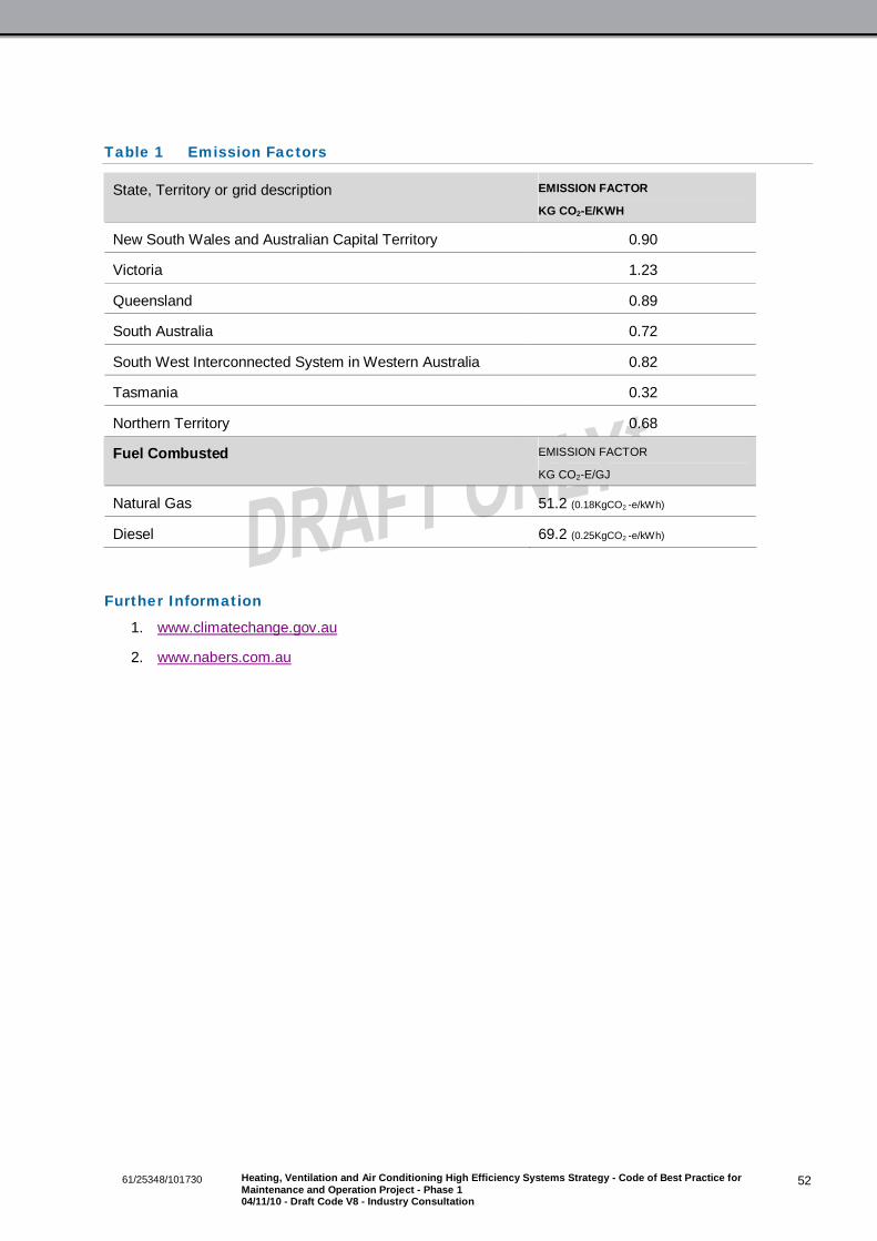
5261/25348/101730 Heating, Ventilation and Air Conditioning High Efficiency Systems Strategy - Code of Best Practice forMaintenance and Operation Project - Phase 104/11/10 - Draft Code V8 - Industry Consultation
Table 1 Emission Factors
State, Territory or grid description EMISSION FACTOR
KG CO2-E/KWH
New South Wales and Australian Capital Territory 0.90
Victoria 1.23
Queensland 0.89
South Australia 0.72
South West Interconnected System in Western Australia 0.82
Tasmania 0.32
Northern Territory 0.68
Fuel Combusted EMISSION FACTOR
KG CO2-E/GJ
Natural Gas 51.2 (0.18KgCO2 -e/kWh)
Diesel 69.2 (0.25KgCO2 -e/kWh)
Further Information
1. www.climatechange.gov.au
2. www.nabers.com.au

5361/25348/101730 Heating, Ventilation and Air Conditioning High Efficiency Systems Strategy - Code of Best Practice forMaintenance and Operation Project - Phase 104/11/10 - Draft Code V8 - Industry Consultation
Appendix A
Checklist: Building Owner

5461/25348/101730 Heating, Ventilation and Air Conditioning High Efficiency Systems Strategy - Code of Best Practice forMaintenance and Operation Project - Phase 104/11/10 - Draft Code V8 - Industry Consultation
Building Owner Checklist
Task Action Section/Comments
Develop Policies1 Prioritise efficient HVAC maintenance2 Ensure environment policy is in place. 3.133 Ensure maintenance policy is in place. 3.14
Ensure that agreed service conditions inleases (temperature, humidity, after hoursoperations) are not wasteful. Wherenecessary, negotiate with tenants.Develop Maintenance Strategy
4 Ensure maintenance strategy is developed. 3.145 Ensure HVAC benchmarks and energy
efficiency KPIs are developed.3.16
6 Consider incentives to key stakeholders forefficient operation & maintenance of HVACsystems.
7 Where an existing contract has a long timeremaining to run, discuss and negotiate theabove with the contractor.Allocate Resources
8 Allocate a budget to enable efficientmaintenance to be carried out.
3.13
9 Employ suitably trained staff to procure andmanage HVAC maintenance contract
Facility manager role.
Monitor Progress
10 Have regular progress meetings with thefacility manager.
11 Monitor HVAC KPIs and buildingperformance targets.Building Operation
12 Ensure Building User Guide (BUG) isdeveloped and distributed to occupants.
5.3
13 Develop fit out guidelines/tenancy rules andensure that they are in place.
5.4
14 Ensure key documentation is in place witheasy access to contractors: O&M manuals,as fitted drawings, maintenance log booksand commissioning data.

GHD | Department of Climate Change & Energy Efficiency –04/11/10 - Draft Code V8 - Industry Consultation
Appendix B
Checklist: Facility Manager

GHD | Department of Climate Change & Energy Efficiency –04/11/10 - Draft Code V8 - Industry Consultation
Facility Manager Checklist
Task Action Section/Comments
Develop Policies
1 Confirm/develop maintenance &environment policies with building owner.
3.13
Allocate Resources
2 Develop realistic maintenance budget withbuilding owner.
3.13
3 Ensure adequate resources are available tospecify, procure and manage maintenancecontract.
3.17, 3.19
Develop Maintenance Strategy 3.14
4 Implement maintenance strategy.
5 Develop with building owner HVAC KPIsand building performance targets.
6 Develop incentives for contractor to carryout efficient HVAC maintenance.
7 Prioritise actions that would improveefficiencies and make cost savings. Ifnecessary perform energy & water audits.
Prepare Documentation8 Ensure that an asset register is available
and up to date.3.15, See Appendix H for sample assetregister.
9 Develop environmental impact rating (EIR)for HVAC equipment.
Appendix H
10 Ensure key documentation is in place witheasy access to contractors: O&M manuals,as fitted drawings, maintenance log booksand commissioning data.
5.
Procure Maintenance Contract 3.17
11 Decide on maintenance contract types e.g.SLAs, PPM.
12 Check prospective maintenance contractors’environmental policy.
13 Check prospective maintenance contractors’track record with efficient HVACmaintenance.
Check maintenance provider references.
14 Check prospective maintenance contractors’capability on BMS and controls systems.
15 Check prospective maintenance contractors’business management and reportingsystems.Communication
16 Ensure robust communication methods arein place between the stakeholders.

GHD | Department of Climate Change & Energy Efficiency –04/11/10 - Draft Code V8 - Industry Consultation
Task Action Section/Comments
Maintenance Management 3.1917 Check that the maintenance contractor has
adequate resources and supervision todeliver the specified outcomes.
18 Discuss with maintenance provider and finetune HVAC KPIs and benchmarks.
19 Check the required logbooks are in place.Monitoring 3.20
20 Ensure metering is in place to monitorelectricity, gas and water consumption flowsthroughout the building.
21 Regularly check on KPIs. Use readilyavailable means such as ½ hour time of usedata from the electricity utility companies, tocheck unusual consumption patters duringpublic holidays and after hours.
22 Ensure maintenance log books are in placefor major HVAC equipment and are beingupdated
23 Review HVAC maintenance procedures.24 Carryout maintenance audits and reviews of
maintenance practices.Building Operation 4.
25 Develop building user guide (BUG) andensure distribution to occupants.
26 Are fit out guidelines/tenancy rules in place? Y/N
27 Ensure that agreed service conditions inleases (T, RH, after hours operations) arenot wasteful. Where necessary, negotiatewith tenants.
28 Increase temperature dead bands in areassuch as entry lobbies, lift motor rooms andin office areas where possible.
29 Is there adequate sub-metering (electricity,gas water) installed to monitor the KPIs andfor NABERS purposes?
30 Is energy monitoring and targeting beingcarried out.Building Maintenance
31 Assess building air tightness and insulation32 Assess efficiency and maintenance of chiller
system3.2
33 Assess efficiency and maintenance ofcooling towers
3.3
34 Assess efficiency and maintenance of AHUsand VAV boxes
3.4
35 Assess efficiency and maintenance ofBoilers
3.5
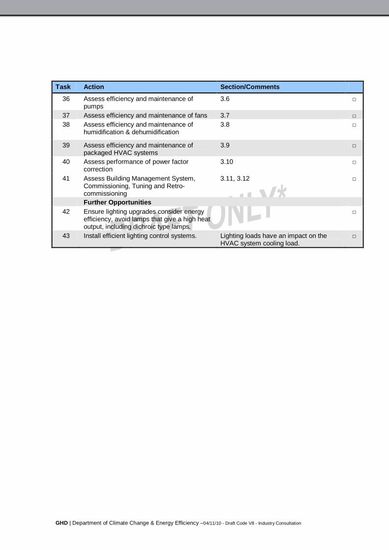
GHD | Department of Climate Change & Energy Efficiency –04/11/10 - Draft Code V8 - Industry Consultation
Task Action Section/Comments
36 Assess efficiency and maintenance ofpumps
3.6
37 Assess efficiency and maintenance of fans 3.738 Assess efficiency and maintenance of
humidification & dehumidification3.8
39 Assess efficiency and maintenance ofpackaged HVAC systems
3.9
40 Assess performance of power factorcorrection
3.10
41 Assess Building Management System,Commissioning, Tuning and Retro-commissioning
3.11, 3.12
Further Opportunities42 Ensure lighting upgrades consider energy
efficiency, avoid lamps that give a high heatoutput, including dichroic type lamps.
43 Install efficient lighting control systems. Lighting loads have an impact on theHVAC system cooling load.

GHD | Department of Climate Change & Energy Efficiency –04/11/10 - Draft Code V8 - Industry Consultation
Appendix C
Checklist: Tenant
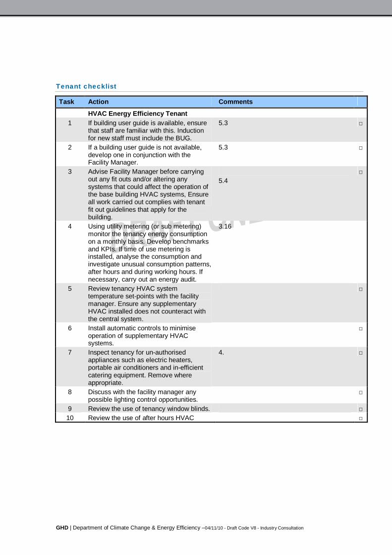
GHD | Department of Climate Change & Energy Efficiency –04/11/10 - Draft Code V8 - Industry Consultation
Tenant checklist
Task Action Comments
HVAC Energy Efficiency Tenant1 If building user guide is available, ensure
that staff are familiar with this. Inductionfor new staff must include the BUG.
5.3
2 If a building user guide is not available,develop one in conjunction with theFacility Manager.
5.3
3 Advise Facility Manager before carryingout any fit outs and/or altering anysystems that could affect the operation ofthe base building HVAC systems, Ensureall work carried out complies with tenantfit out guidelines that apply for thebuilding.
5.4
4 Using utility metering (or sub metering)monitor the tenancy energy consumptionon a monthly basis. Develop benchmarksand KPIs. If time of use metering isinstalled, analyse the consumption andinvestigate unusual consumption patterns,after hours and during working hours. Ifnecessary, carry out an energy audit.
3.16
5 Review tenancy HVAC systemtemperature set-points with the facilitymanager. Ensure any supplementaryHVAC installed does not counteract withthe central system.
6 Install automatic controls to minimiseoperation of supplementary HVACsystems.
7 Inspect tenancy for un-authorisedappliances such as electric heaters,portable air conditioners and in-efficientcatering equipment. Remove whereappropriate.
4.
8 Discuss with the facility manager anypossible lighting control opportunities.
9 Review the use of tenancy window blinds.10 Review the use of after hours HVAC

GHD | Department of Climate Change & Energy Efficiency –04/11/10 - Draft Code V8 - Industry Consultation
Appendix D
Checklist: Maintenance Provider

GHD | Department of Climate Change & Energy Efficiency –04/11/10 - Draft Code V8 - Industry Consultation
Maintenance provider checklist
Task Action Comments1.0 HVAC Energy Efficiency Maintenance
Implementation.Policies and Maintenance Contract
1 Obtain details of the maintenance, energy andenvironment policies from the facility manager.Ensure these objectives are met.
3.13
2 Make recommendations regarding scheduledmaintenance frequencies, should deficiencies bedetected.
3.14
Resources3 Ensure suitably trained/qualified maintenance
personnel are utilised to meet the contractrequirements.
3.18
Communication4 Ensure that suitable communication methods are
in place.Asset Register
5 Advise the facility manager of any inaccuracies.Continuously update the asset register.
3.15
6 Identify energy & water saving opportunities andinclude EIR in asset register
Appendix H
1.1 Building Infiltration, Insulation and Shading.1 Check the building entrance auto doors are
operating satisfactorily and are not openunnecessarily and for excessive periods of time.
2 Inspect external doors for gaps/leaking doorseals that allow infiltration.
3 Inspect the condition of windows, frames andseals.
4 Inspect for doors left open or forced openunnecessarily.
5 Inspect for ceiling tiles to be in place and in goodcondition with no air gaps.
6 Inspect inside ceilings for displaced insulation.7 Inspect the condition and adequacy of the
building roof insulation.8 Inspect for perimeter air leakage e.g. at service
penetrations.
9 Inspect floor-wall-ceiling joints for air gaps.10 Inspect window shading devices and their
operation.
11 Consider installing shading devices, includingwindow tinting to W and N facades.
12 Consider installation of automatic blinds.

GHD | Department of Climate Change & Energy Efficiency –04/11/10 - Draft Code V8 - Industry Consultation
Task Action Comments13 Investigate feasibility of painting the roof with a
solar reflective paint.Likely to be cost effective if the roofinsulation is poor and/or the roof voidis used as part of the air distributionsystem.
1.2 Chiller1 Ensure logbooks are in place and up to date. 3.2, 3.21 & 5.22 Ensure maintenance schedules comply with
manufacturers’ recommendations and AIRAHDA19.
3.2
3 Ensure chiller control sensors are calibrated andefficient chiller sequencing is in place.
3.2
4 Ensure control strategies are in place to minimisespurious chiller system operation- outsidetemperature lock out and cooling call verification.
3.2
5 Ensure control strategies are in place tomaximise chiller system efficiency- chilled water& condenser water reset.
3.2
6 Ensure KPIs are in place with the necessary sub-metering to monitor performance of chilled watersystem.
3.2 & 3.16
7 Utilise BMS to monitor performance of chillerincluding COP, condenser & evaporator pressuredrops and temperature approaches.
3.11
8 Check that chiller unit is not oversized for lowload operation, especially after hours.
3.2
9 Inspect chiller and associated pipe workinsulation for thickness and for signs ofdeterioration.
10 Consider replacing obsolete chillers units withnew efficient chillers. Optimise selection of newchillers, don’t replace like for like.
3.2
11 Install BMS interface to chiller controls1.4 Cooling Towers1 Ensure logbooks are in place and up to date. 3.3, 3.21 & 5.22 Ensure maintenance schedules comply with
manufacturers’ recommendations and AIRAHDA19.
3.3
3 Review specialist water treatment contract.Ensure TDS controls are set up properly.
4 Check visually for signs of leakage or overflowwhen towers are in operation and when stopped.
3.3
5 Check drift eliminators are fitted and in goodcondition.
3.3
6 Ensure control strategies are in place to optimisecooling tower staging and minimise fan energyconsumption. E.g. wet bulb tracking.

GHD | Department of Climate Change & Energy Efficiency –04/11/10 - Draft Code V8 - Industry Consultation
Task Action Comments7 Ensure KPIs are in place with the necessary sub-
metering to monitor performance of cooling towersystem.
3.3 & 3.16
8 Replace obsolete equipment with modern energy& water efficient units.
9 Consider the recovery of bleed water forpurposes such as irrigation or flushing toilets.
3.3
10 Ensure water sub-meters are installed formonitoring consumption. Monitor through BMS ifinstalled, with alarm functions.
3.11
11 When replacing obsolete equipment, consideroptions such as adiabatic coolers and for largeinstallations, using sea or river water.
3.3
12 Consider alternative water sources such asrainwater or reclaimed condensate from AHUs.
13 Consider monitoring performance of coolingtowers through BMS.
3.11
1.5 Air Handling Units and VAV Boxes1 Ensure logbooks are in place and up to date. 3.4, 3.21 & 5.2
2 Ensure maintenance schedules comply withmanufacturer’s recommendations and AIRAHDA19.
3.4
3 Where BMS is installed set trends on BMS toverify efficient operation of VSDs, economy cycledamper operation, checks for leaking valves etc.
Regular monitoring on the BMSrequired.
4 Ensure correct interaction between VAV boxesand AHU and . Set up diagnostic screens tomonitor correct performance of VAV boxes.
3.4
5 Ensure zone set points are not altered in an ad-hoc manner in an attempt to ‘fix’ underlyingproblems
6 Check for air leakage from AHU’s and ductwork. 3.4
7 Check condition of ductwork for condition andobvious signs of air leakage.
3.4
8 Rebalance and recommission the system. Readjust minimum and maximum air flow rates onVAV boxes to minimise over cooling and re-heat.
3.4
9 Eliminate (or minimise) humidification and de-humidification.
3.8
10 Replace systems that are at end of life withmodern more energy efficient units.
11 Install VSD’s for variable speed fan operation.
12 Consider upgrading of controls with a BMSinterface.
3.11

GHD | Department of Climate Change & Energy Efficiency –04/11/10 - Draft Code V8 - Industry Consultation
Task Action Comments13 Investigate possibility of recovering heat from
exhaust air.Through the use of energy recoverydevices such as run-around coils,thermal wheels and cross flow heatexchangers.
1.6 Heating Boilers and Systems
1 Ensure logbooks are in place and up to date. 3.21 & 5.2
2 Ensure maintenance schedules comply withmanufacturers’ recommendations and AIRAHDA19.
3.5
3 Where BMS is installed set trends, targets andalarms on energy consumed, flow & returntemperatures etc.
Regular monitoring on the BMSrequired.
4 Ensure control strategies are in place to minimisespurious boiler system operation. E.g. outsidetemperature lock out and heating call verification.
3.5
5 Ensure control strategies are in place tomaximise boiler and system efficiency. e.g.heating temperature re-set.
3.5
6 Check condition of thermal insulation and repairwhere necessary. Install thermal insulation overpipeline components.
3.5
7 Replace boiler with more energy efficient boilertype e.g. condensing boiler.
3.5
8 Consider the installation of a flue gasrecovery/economiser system.
1.7 Pumps and Distribution Systems1 Ensure maintenance schedules comply with
manufacturers’ recommendations and AIRAHDA19.
3.6
2 Routinely check for water leaks from pipe workand components
3.6
3 Ensure non essential pumps are switched off
4 Investigate whether pumps are throttled at indexrun
3.6
5 Where VSD’s are installed for control purposes,set up trends on BMS or VSD and investigatewhether system modulates
6 If not installed already, consider VSD’s.7 Replace pump to match system loading. 3.68 Consider conversion of constant volume systems
to variable volume primary/secondary systems.3.6
1.8 Fans1 Ensure maintenance schedules comply with
manufacturers’ recommendations and AIRAHDA19.
3.7

GHD | Department of Climate Change & Energy Efficiency –04/11/10 - Draft Code V8 - Industry Consultation
Task Action Comments2 Routinely check for air leaks from ductwork and
components3.4 & 3.7
3 Ensure non essential fans are switched off 3.74 Investigate whether fans are throttled at index
run3.7
5 Where VSD’s are installed for control purposes,set up trends on BMS or VSD and investigatewhether system modulates
6 If not installed already, consider VSD’s.7 Replace fan to match system loading. 3.78 Consider conversion of constant volume systems
to variable volume systems.3.7
1.9 Motors and VSD’s1 Ensure maintenance schedules comply with
manufacturers’ recommendations and AIRAHDA19.
3.4
2 Ensure belt and pulley alignment is regularlychecked
3 Ensure VSD’s modulate correctly in variablevolume systems.
4 Do not re-wind motors that operate for longhours, typically more than 100 hours per year.Have a replacement policy that specifies highefficiency motors.
5 Size motors correctly to avoid under sizing (couldlead to premature failure) and over sizing(potentially in-efficient).
6 Ensure that the system has capabilities formonitoring the HVAC systems and KPIs.
2.0 Humidification & Dehumidification7 Ensure maintenance schedules comply with
manufacturers’ recommendations and AIRAHDA19.
3.8
8 Investigate whether humidification and activedehumidification exists. Report to FacilityManager
3.8
9 Log operation of humidification and active de-humidification, preferably through BMS
3.8
10 Maximise use of economy cycle, to minimiseactive humidification and dehumidification
3.8
2.1 Packaged HVAC Systems1 Ensure maintenance schedules comply with
manufacturers’ recommendations and AIRAHDA19.
3.9
2 Minimise operation of units, based on timeschedules and temperature set points
3.9
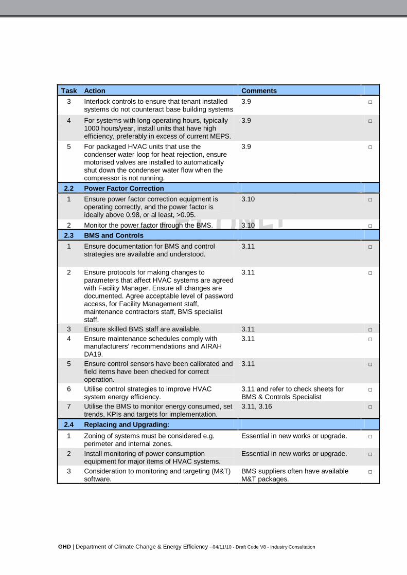
GHD | Department of Climate Change & Energy Efficiency –04/11/10 - Draft Code V8 - Industry Consultation
Task Action Comments3 Interlock controls to ensure that tenant installed
systems do not counteract base building systems3.9
4 For systems with long operating hours, typically1000 hours/year, install units that have highefficiency, preferably in excess of current MEPS.
3.9
5 For packaged HVAC units that use thecondenser water loop for heat rejection, ensuremotorised valves are installed to automaticallyshut down the condenser water flow when thecompressor is not running.
3.9
2.2 Power Factor Correction1 Ensure power factor correction equipment is
operating correctly, and the power factor isideally above 0.98, or al least, >0.95.
3.10
2 Monitor the power factor through the BMS. 3.102.3 BMS and Controls1 Ensure documentation for BMS and control
strategies are available and understood.3.11
2 Ensure protocols for making changes toparameters that affect HVAC systems are agreedwith Facility Manager. Ensure all changes aredocumented. Agree acceptable level of passwordaccess, for Facility Management staff,maintenance contractors staff, BMS specialiststaff.
3.11
3 Ensure skilled BMS staff are available. 3.114 Ensure maintenance schedules comply with
manufacturers’ recommendations and AIRAHDA19.
3.11
5 Ensure control sensors have been calibrated andfield items have been checked for correctoperation.
3.11
6 Utilise control strategies to improve HVACsystem energy efficiency.
3.11 and refer to check sheets forBMS & Controls Specialist
7 Utilise the BMS to monitor energy consumed, settrends, KPIs and targets for implementation.
3.11, 3.16
2.4 Replacing and Upgrading:1 Zoning of systems must be considered e.g.
perimeter and internal zones.Essential in new works or upgrade.
2 Install monitoring of power consumptionequipment for major items of HVAC systems.
Essential in new works or upgrade.
3 Consideration to monitoring and targeting (M&T)software.
BMS suppliers often have availableM&T packages.
GHD | Department of Climate Change & Energy Efficiency –04/11/10 - Draft Code V8 - Industry Consultation
Appendix E
Checklist: Energy & Maintenance Auditor
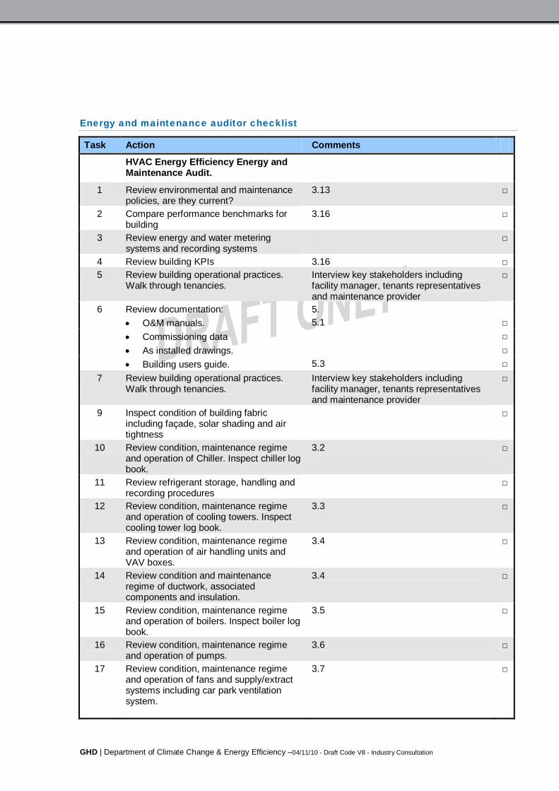
GHD | Department of Climate Change & Energy Efficiency –04/11/10 - Draft Code V8 - Industry Consultation
Energy and maintenance auditor checklist
Task Action Comments
HVAC Energy Efficiency Energy andMaintenance Audit.
1 Review environmental and maintenancepolicies, are they current?
3.13
2 Compare performance benchmarks forbuilding
3.16
3 Review energy and water meteringsystems and recording systems
4 Review building KPIs 3.165 Review building operational practices.
Walk through tenancies.Interview key stakeholders includingfacility manager, tenants representativesand maintenance provider
6 Review documentation: 5. O&M manuals. 5.1 Commissioning data As installed drawings. Building users guide. 5.3
7 Review building operational practices.Walk through tenancies.
Interview key stakeholders includingfacility manager, tenants representativesand maintenance provider
9 Inspect condition of building fabricincluding façade, solar shading and airtightness
10 Review condition, maintenance regimeand operation of Chiller. Inspect chiller logbook.
3.2
11 Review refrigerant storage, handling andrecording procedures
12 Review condition, maintenance regimeand operation of cooling towers. Inspectcooling tower log book.
3.3
13 Review condition, maintenance regimeand operation of air handling units andVAV boxes.
3.4
14 Review condition and maintenanceregime of ductwork, associatedcomponents and insulation.
3.4
15 Review condition, maintenance regimeand operation of boilers. Inspect boiler logbook.
3.5
16 Review condition, maintenance regimeand operation of pumps.
3.6
17 Review condition, maintenance regimeand operation of fans and supply/extractsystems including car park ventilationsystem.
3.7
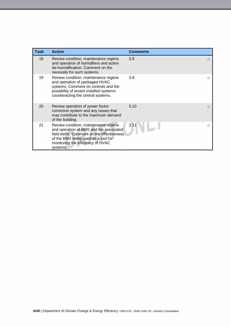
GHD | Department of Climate Change & Energy Efficiency –04/11/10 - Draft Code V8 - Industry Consultation
Task Action Comments
18 Review condition, maintenance regimeand operation of humidifiers and activede-humidification. Comment on thenecessity for such systems.
3.8
19 Review condition, maintenance regimeand operation of packaged HVACsystems. Comment on controls and thepossibility of tenant installed systemscounteracting the central systems.
3.9
20 Review operation of power factorcorrection system and any issues thatmay contribute to the maximum demandof the building.
3.10
21 Review condition, maintenance regimeand operation of BMS and the associatedfield items. Comment on the effectivenessof the BMS being used as a tool formonitoring the efficiency of HVACsystems.
3.11

GHD | Department of Climate Change & Energy Efficiency –04/11/10 - Draft Code V8 - Industry Consultation
Appendix F
Checklist: Controls Contractor

GHD | Department of Climate Change & Energy Efficiency –04/11/10 - Draft Code V8 - Industry Consultation
Controls specialist checklist
Task Action CommentsControls/BMS Maintenance & Operation
1 Review the overall capability of the BMSand effectiveness of its utilisation withregards to delivering the control,monitoring, reporting and diagnosticfunctions required by the buildingsperformance objectives.
3.11
2 Discuss with Facility Manager and otherkey stakeholders, any change managementprotocols, with regards to alteringoperational set points and controlstrategies.
3 Review current maintenance practices forBMS. Are maintenance schedules asrequired (AIRAH DA19) and tomanufacturer’s recommendations?
3.11
4 Ensure a BMS logbook is in place and keptup to date with regards to changedocumentation.
5.2
5 Ensure control sensors have beencalibrated and field items are operational.
3.11
6 Where temperature sensors are mountedon external walls, check the quality of cablegland sealing, to ensure air does not leakpast sensor and affect its reading.
7 Are zone sensors located in representativepositions? Check that temperature sensorsare not affected by external factors such asheat gains from office equipment.
Y/N
8 Check for excessive operation of HVACsystems, such as whole building systemsbeing operated to serve a small area.
3.11
13 Review BMS capability for detection offailures, non performance of equipment andnon-achievement of KPIs. Check thatalarms are set on the BMS and the withsatisfactory communication methods forexception reporting.
3.11 & 3.16
9 Check that controls have not been over-ridden for a short-term purpose and notreset afterwards.
10 Check that time scheduling is accurateincluding the programming of local publicholidays.
3.11
11 Check that ancillary systems do notoperate unnecessarily, after hours whenmain plant is not in operation.

GHD | Department of Climate Change & Energy Efficiency –04/11/10 - Draft Code V8 - Industry Consultation
Task Action Comments12 Check for simultaneous operation of
conflicting items of plant. E.g. leaking hotwater and chilled water valves. Wherepossible set up automatic alarm functions.
3.11
13 Ensure temperature control set points arenot over conservative. E.g. can the heatingand cooling requirements for areas such asentrance lobbies be set back?
3.11
14 Ensure pressure control set points onVSD’s are not too high, where possible usesmart control strategies including criticalzone reset.
15 Where VSDs are installed in variablevolume &/or pressure systems, ensuretrending is set up to monitor that thesystems are modulating rather thanoperating at fixed speed.
16 Is optimum start/stop programmed?
17 Is night purge used? Y/N18 Does the heating system have outside
temperature lock out?Y/N
19 Does the heating system have flowtemperature re-set?
Y/N
20 Does the cooling system have outsidetemperature lock out?
Y/N
21 Does the cooling system have flowtemperature re-set?
Y/N
22 Does the economy cycle operatesatisfactorily?
Y/N
23 Utilise the BMS to monitor energyconsumed, set trends, KPIs and targets forimplementation:
Discuss and agree with the facilitymanager and maintenance provider.
Chiller unit COP monitoring HVAC energy consumption
Cooling tower water consumption
Monitoring and targeting of energyconsumption

GHD | Department of Climate Change & Energy Efficiency –04/11/10 - Draft Code V8 - Industry Consultation
Appendix G
Checklist: Designer
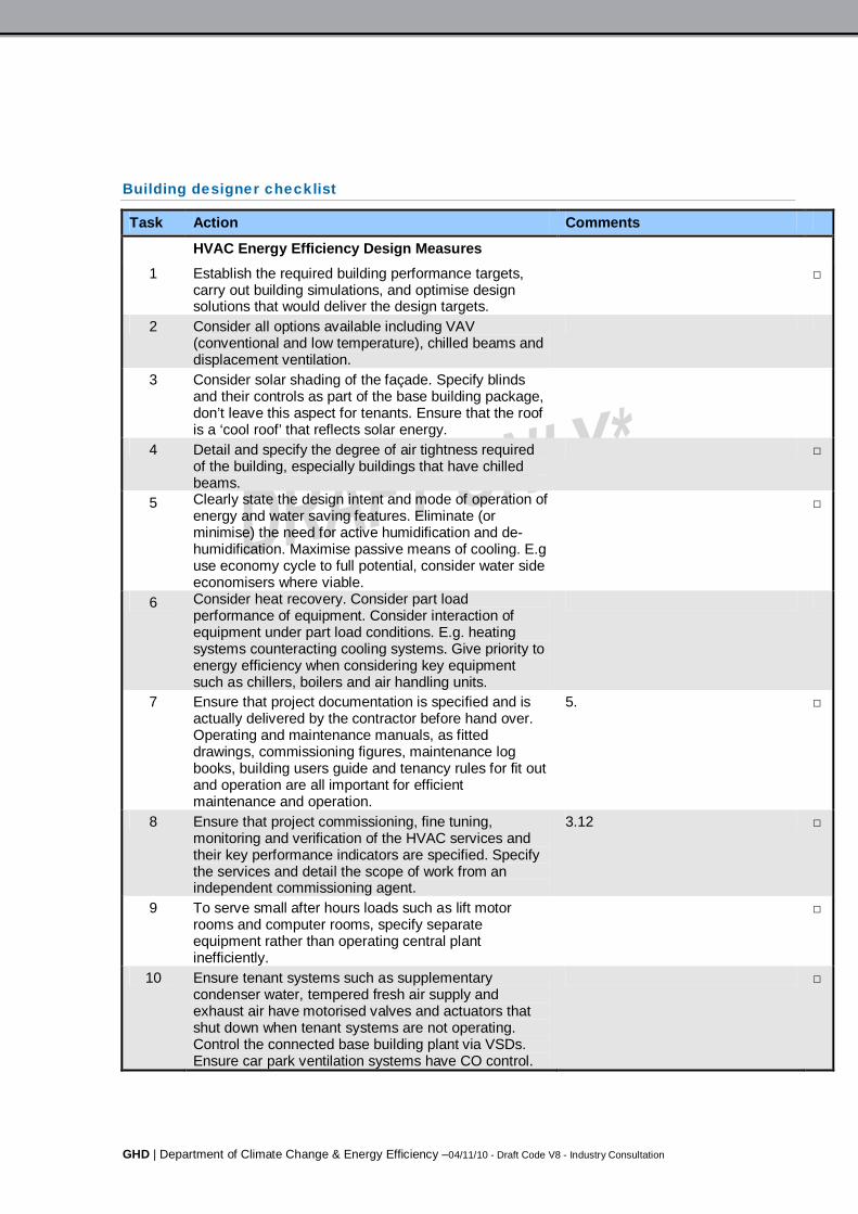
GHD | Department of Climate Change & Energy Efficiency –04/11/10 - Draft Code V8 - Industry Consultation
Building designer checklist
Task Action Comments
HVAC Energy Efficiency Design Measures1 Establish the required building performance targets,
carry out building simulations, and optimise designsolutions that would deliver the design targets.
2 Consider all options available including VAV(conventional and low temperature), chilled beams anddisplacement ventilation.
3 Consider solar shading of the façade. Specify blindsand their controls as part of the base building package,don’t leave this aspect for tenants. Ensure that the roofis a ‘cool roof’ that reflects solar energy.
4 Detail and specify the degree of air tightness requiredof the building, especially buildings that have chilledbeams.
5 Clearly state the design intent and mode of operation ofenergy and water saving features. Eliminate (orminimise) the need for active humidification and de-humidification. Maximise passive means of cooling. E.guse economy cycle to full potential, consider water sideeconomisers where viable.
6 Consider heat recovery. Consider part loadperformance of equipment. Consider interaction ofequipment under part load conditions. E.g. heatingsystems counteracting cooling systems. Give priority toenergy efficiency when considering key equipmentsuch as chillers, boilers and air handling units.
7 Ensure that project documentation is specified and isactually delivered by the contractor before hand over.Operating and maintenance manuals, as fitteddrawings, commissioning figures, maintenance logbooks, building users guide and tenancy rules for fit outand operation are all important for efficientmaintenance and operation.
5.
8 Ensure that project commissioning, fine tuning,monitoring and verification of the HVAC services andtheir key performance indicators are specified. Specifythe services and detail the scope of work from anindependent commissioning agent.
3.12
9 To serve small after hours loads such as lift motorrooms and computer rooms, specify separateequipment rather than operating central plantinefficiently.
10 Ensure tenant systems such as supplementarycondenser water, tempered fresh air supply andexhaust air have motorised valves and actuators thatshut down when tenant systems are not operating.Control the connected base building plant via VSDs.Ensure car park ventilation systems have CO control.
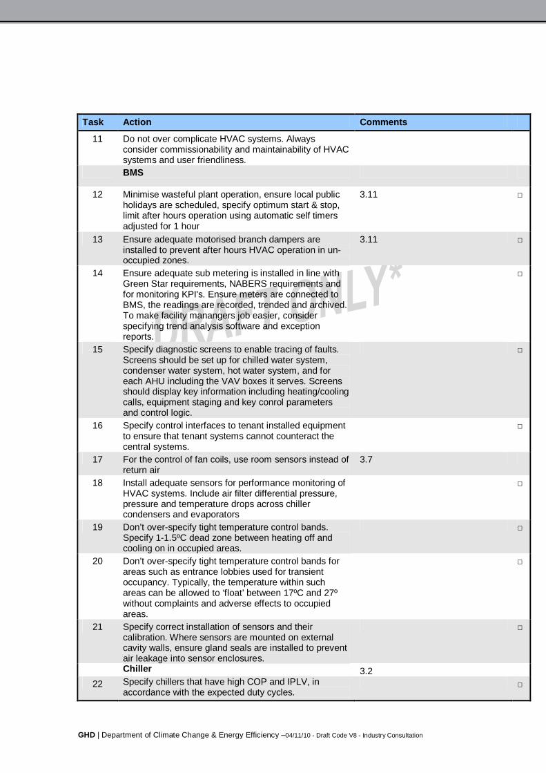
GHD | Department of Climate Change & Energy Efficiency –04/11/10 - Draft Code V8 - Industry Consultation
Task Action Comments
11 Do not over complicate HVAC systems. Alwaysconsider commissionability and maintainability of HVACsystems and user friendliness.BMS
12 Minimise wasteful plant operation, ensure local publicholidays are scheduled, specify optimum start & stop,limit after hours operation using automatic self timersadjusted for 1 hour
3.11
13 Ensure adequate motorised branch dampers areinstalled to prevent after hours HVAC operation in un-occupied zones.
3.11
14 Ensure adequate sub metering is installed in line withGreen Star requirements, NABERS requirements andfor monitoring KPI's. Ensure meters are connected toBMS, the readings are recorded, trended and archived.To make facility manangers job easier, considerspecifying trend analysis software and exceptionreports.
15 Specify diagnostic screens to enable tracing of faults.Screens should be set up for chilled water system,condenser water system, hot water system, and foreach AHU including the VAV boxes it serves. Screensshould display key information including heating/coolingcalls, equipment staging and key conrol parametersand control logic.
16 Specify control interfaces to tenant installed equipmentto ensure that tenant systems cannot counteract thecentral systems.
17 For the control of fan coils, use room sensors instead ofreturn air
3.7
18 Install adequate sensors for performance monitoring ofHVAC systems. Include air filter differential pressure,pressure and temperature drops across chillercondensers and evaporators
19 Don’t over-specify tight temperature control bands.Specify 1-1.5ºC dead zone between heating off andcooling on in occupied areas.
20 Don’t over-specify tight temperature control bands forareas such as entrance lobbies used for transientoccupancy. Typically, the temperature within suchareas can be allowed to ‘float’ between 17ºC and 27ºwithout complaints and adverse effects to occupiedareas.
21 Specify correct installation of sensors and theircalibration. Where sensors are mounted on externalcavity walls, ensure gland seals are installed to preventair leakage into sensor enclosures.Chiller 3.2
22 Specify chillers that have high COP and IPLV, inaccordance with the expected duty cycles.

GHD | Department of Climate Change & Energy Efficiency –04/11/10 - Draft Code V8 - Industry Consultation
Task Action Comments
23 Apply whole of life costing- consider water cooled,adiabatic and air cooled options.
6.5
24 Consider variable volume chilled water pumping.
25 Consider chilled water re-set and condenser waterreset.
26 Ensure that chillers are sequenced correctly to deliverthe most efficient output for the prevailing chillerdemand. Stage chillers up/down based on current drawof compressors rather than kWr.
27 Minimise spurious cooling demand calls- specify anambient low temperature lock out and giveconsideration to cooling calls- avoid the possibility of afaulty motorised valve or broken VAV box causing acooling call.
28 Specify electricity sub metering and chiller thermalmetering to enable monitoring chiller performance andKPIs.
29 Specify high level interface with BMSBoiler 3.5
30 Specify boilers that have high efficiencies.
31 Minimise heating calls- specify an ambient hightemperature lock out and give consideration to verifyingheating calls- avoid the possibility of a faulty motorisedvalve or broken VAV box causing a heating call.
Cooling Tower 3.332 Optimise selection, combine base building and tenants
supplementary cooling towers together to obtain thelowest approach possible with minimum consumption offan power.
33 Specify a fan sequencing strategy that simultaneouslyoperates all fans in parallel, rather than rampingindividual fans to 100% before staging the next fan.
34 Specify wet bulb tracking system that uses at least twoambient dry bulb/wet bulb sensors (to
35 Install water metering connected to BMS. Set up KPIsand alarm functions to report abnormally high and lowwater consumption
36 Install automatic bleed through TDS system. Monitorthe system through BMS.AHU 3.4
37 Specify low pressure drops on the air and water side.
38 Oversize coils where applicable, to get the mostefficiency out of chillers (higher chilled watertemperatures) and boilers (lower heating watertemperatures using condensing boilers) where feasible.
39 When considering zoning, take into account orientation,variances in heat loads and after hours plant requests
40 Minimise the need for active de-humidification andhumidification

GHD | Department of Climate Change & Energy Efficiency –04/11/10 - Draft Code V8 - Industry Consultation
Task Action Comments
41 Use the economy cycle to maximum potential, in humidareas sense enthalpy of air rather than dry bulbtemperature. Use two enthalpy sensors to check forsensors drifting out of calibration.
42 Control outside air based on CO2 sensing, especiallyimportant for variable occupancy areas.
43 Specify critical zone reset for the control of AHU fansrather than using a fixed static pressure
44 Avoid using hi/low select signal from zone sensors forAHU control zone purposes, the hi/low select signalcould be originating from a zone served by a faulty VAVbox. Use a verification system or an averaging systemto reduce the possibility of a faulty VAV box affectingthe operation of the entire AHU.
45 Use night purge when suitable outdoor conditions exist,use enthalpy sensing in humid climates. Excessive useof night purge (>2 hours) can be counter productive.Disable heating system for a set period (eg. 2 hours)after night purge ceases.
GHD | Department of Climate Change & Energy Efficiency –04/11/10 - Draft Code V8 - Industry Consultation
Appendix H
Asset Register
Typical format

GHD | Department of Climate Change & Energy Efficiency –04/11/10 - Draft Code V8 - Industry Consultation
The following table provides a template for an asset register:
Table 2 Building Name: ABC123 Tower
Type Qty Description Label Make Model Cond.Rating
Location EIR
A/C - Split System -Hi Wall
1 AC1.1 ABC123 Level 1 2
VAV Box 15 V1.1 - V1.15 ABC123 Level 1 1
Chiller - CentrifugalAir Cooled
1 CH1 ABC123 Level 1 Plantroom 3
A/C - AHU (CHW) 1 FCU 1.1 ABC123 xxx xxx 2
Fan - Axial Belt Drive 1 Exhaust FN 1.1 2
Switchboard -Mechanical Services
1 MSSB1 N/A
A/C - Split System -Ducted
1 AC1.2 1
Building ManagementSystem (DDC)
1 BMS 1 Security Room N/A
VSD 1 AHU1.1 VSD1.1 N/A
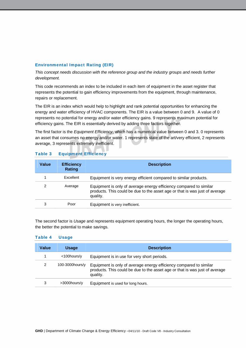
GHD | Department of Climate Change & Energy Efficiency –04/11/10 - Draft Code V8 - Industry Consultation
Environmental Impact Rating (EIR)
This concept needs discussion with the reference group and the industry groups and needs furtherdevelopment.
This code recommends an index to be included in each item of equipment in the asset register thatrepresents the potential to gain efficiency improvements from the equipment, through maintenance,repairs or replacement.
The EIR is an index which would help to highlight and rank potential opportunities for enhancing theenergy and water efficiency of HVAC components. The EIR is a value between 0 and 9. A value of 0represents no potential for energy and/or water efficiency gains. 9 represents maximum potential forefficiency gains. The EIR is essentially derived by adding three factors together.
The first factor is the Equipment Efficiency, which has a numerical value between 0 and 3. 0 representsan asset that consumes no energy and/or water. 1 represents state of the art/very efficient, 2 representsaverage, 3 represents extremely inefficient.
Table 3 Equipment Efficiency
Value EfficiencyRating
Description
1 Excellent Equipment is very energy efficient compared to similar products.
2 Average Equipment is only of average energy efficiency compared to similarproducts. This could be due to the asset age or that is was just of averagequality.
3 Poor Equipment is very inefficient.
The second factor is Usage and represents equipment operating hours, the longer the operating hours,the better the potential to make savings.
Table 4 Usage
Value Usage Description
1 <100hours/y Equipment is in use for very short periods.
2 100-3000hours/y Equipment is only of average energy efficiency compared to similarproducts. This could be due to the asset age or that is was just of averagequality.
3 >3000hours/y Equipment is used for long hours.

GHD | Department of Climate Change & Energy Efficiency –04/11/10 - Draft Code V8 - Industry Consultation
The third factor is equipment rating, which represents the rate at which electricity, gas or water isconsumed.
Table 5 Equipment Rating
Value Rating Description
1 <5kW or ??MJ/hor ??L/s
Equipment is low power.
2 5-50kW Equipment is medium power.
3 >50kW Equipment high power.

GHD | Department of Climate Change & Energy Efficiency –04/11/10 - Draft Code V8 - Industry Consultation
Appendix I
Public Submission Form
Template

GHD | Department of Climate Change & Energy Efficiency –04/11/10 - Draft Code V8 - Industry Consultation
COVER SHEET FOR PUBLIC SUBMISSIONS
Heating, Ventilation and Air Conditioning High Efficiency Systems Strategy - Code ofBest Practice for Maintenance and Operation Project - Phase 1
A cover sheet is required for every submission. Please include contact details so we can confirmreceipt of your submission or contact you if we have any questions about your submission. (Please seeConfidentiality statement below for information on keeping your name or submission confidential).
Table 4 Contact Details
Title
First Name
Last Name
Organisation (if any)
Email Address
Telephone
Street Address
Town / Suburb
State / Territory
Postcode
Date of submission
CONFIDENTIALITY STATEMENT
All submissions will be treated as public documents, unless the author of the submission clearly indicatesthe contrary by marking all or part of the submission as ‘confidential’.
Do you want to keep the entire submission confidential?
Yes, keep all the contents of my submission confidential.
No, publish the text of my submission (for example, on the Department of Climate Change andEnergy Efficiency (DCCEE) website).
Unless you request otherwise, your submission will be published on the relevant Commonwealthgovernment website in full and extracts from submissions may also be reproduced in public documents.The submission will be published including your name and your state / territory, but your other personalinformation (e.g. phone number, email address, postal address) will be kept confidential. If you wouldlike your name to be confidential also, please let us know below.
Do you want to keep your name confidential?
Yes, only publish my state / territory with my submission, e.g. ‘Anonymous, NSW’
No, publish my name or organisation, and my state / territory with my submission, for example ‘J.Smith, WA’ or ‘The Native Vegetation Association, NT’.
If your submission contains the personal information of any third party individuals, please indicate belowif they have not consented to the publication of their information. A request made under the Freedom of

GHD | Department of Climate Change & Energy Efficiency –04/11/10 - Draft Code V8 - Industry Consultation
Information Act 1982 for access to a submission marked confidential will be determined in accordancewith the Act.
Third Party individual/s referenced in this submission.
consent/s to the publication of their information.
does not consent to the publication of their information.
Additional information
GHD | Department of Climate Change & Energy Efficiency –04/11/10 - Draft Code V8 - Industry Consultation
GHD
GHD House, 239 Adelaide Tce. Perth, WA 6004P.O. Box 3106, Perth WA 6832T: 61 8 6222 8222 F: 61 8 6222 8555 E: [email protected]
61/25348/101730
© GHD 2010
This document is and shall remain the property of GHD. The document may only be used for the purposefor which it was commissioned and in accordance with the Terms of Engagement for the commission.Unauthorised use of this document in any form whatsoever is prohibited.
Document Status
Reviewer Approved for IssueRevNo. Author
Name Signature Name Signature Date
Prelim J.G. Wilson L. LecamwasamP. Dunn
Client Review 30.07.10
Prelim2 J.G. Wilson D. Chokolich Client Review 02.08.10
Draft 3 J.G. Wilson L. Lecamwasam Client Review 26.08.10
Draft 4 J.G. Wilson L. Lecamwasam Client Review 31.08.10
Draft 5 J.G. Wilson L. Lecamwasam Client Review 30.09.10
Draft 6 J.G. Wilson L. Lecamwasam Client Review 15.10.10
Draft 7 J.G. Wilson L. Lecamwasam Client Review 29.10.10
Draft 8 J.G. Wilson L. Lecamwasam Industry Consultation 04.11.10