hf/vhf/uhf go-box and antenna system for transportable ... & antennas.pdf · duplexer for 2m...
TRANSCRIPT

1
HF/VHF/UHF Go-Boxand Antenna System for
Transportable Amateur RadioOperation
Jerry D. Kendrick, PhD
NG6R, LA County DCS T-03
February 2015http://www.qsl.net/lmtdcs/2015-02-07_Go-Box & antennas.pdf

2
Briefing Topics
• Objective and requirements• Final photos, front and rear views• Key operational details• Go-box in field deployment• Portable antenna system• Construction components
– Mechanical structure– Key electronics– Supporting electronics– Antennas
• Lessons learned• Future enhancements

3
Objective
Design, acquire essential components,and assemble a transportableamateur radio station
– Capable of operating on most bandsand modes used by ham radioemergency communicators
– Compact; easy to transport, deploy andoperate; using either commercial orbackup power sources
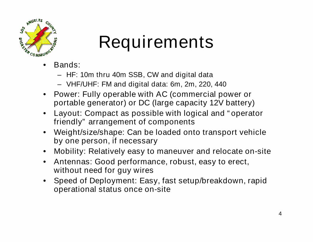
4
Requirements• Bands:
– HF: 10m thru 40m SSB, CW and digital data
– VHF/UHF: FM and digital data: 6m, 2m, 220, 440
• Power: Fully operable with AC (commercial power orportable generator) or DC (large capacity 12V battery)
• Layout: Compact as possible with logical and “operatorfriendly” arrangement of components
• Weight/size/shape: Can be loaded onto transport vehicleby one person, if necessary
• Mobility: Relatively easy to maneuver and relocate on-site
• Antennas: Good performance, robust, easy to erect,without need for guy wires
• Speed of Deployment: Easy, fast setup/breakdown, rapidoperational status once on-site

5
Ham radio HF/VHF/UHF go-boxfor transportable operation (front)
(Emergency/disaster communications, Field Day, etc.)8U rolling 19” rack
AC power distribution unitwith pull-out lamps
ADI VHF/UHF transceivers; leftto right: 2m, 220, 440
Left: MFJ switching P.S.
Middle: HF transceiver speaker
Right: Power/SWR meter for 2mand 440 (via duplexer)
Left: MFJ antenna tuner
Right: Alinco HF transceiver
SignaLink sound card
1U lockable drawer formanuals, microphonesduring transit and smallcomponents

6
Ham radio HF/VHF/UHF go-boxfor transportable operation (rear)
(Emergency/disaster communications, Field Day, etc.)
8U rolling 19” rack
Duplexer for 2m and 440
Three forward-facing individualspeakers behind 1U panelfor 2m, 220 and 440transceivers
SO-239 to 220 antenna
RIGrunner DC powerdistribution unit
Rear of 1U lockable drawer formanuals and small parts
PL-259 w/barrel adaptor to2m/440 dual band antenna
PL-259 w/barrel adaptor to HFantenna
AC power distribution unit

7
Key operational details
• Thin Alinco DX-70 HF front-endunit can be easily detached andoperated 4’ from Go-box ifconvenient
• “Tuning” switch added to frontright edge of Go-box to quicklytune HF rig at 10W beforeoperating at 100W; CW keyer1/8” jack also added to this plate
• Fuses selected to matchequipment needs: 40A input,25A HF rig, 15A for three V/UHFtransceivers, 1A for displaylamps in antenna tuner

8
Go-Box in transport vehicle
High-capacity12V battery
Large rotating table enabling easyrear access for making connections

9
Views of deployed antenna masts
5-section, 20’ heavy-duty aluminumflagpole from Harbor Freight with 4’wooden pole attached to top section
3-section, 23’ extension pole fromLowe’s (right in photo), onlypartially extended here

10
Primary antenna array
2m homemade lightweight“cheap vertical”; acceptableperformance on 440 MHz usingVHF/UHF diplexer in Go-Box
MFJ extendable dipole(6m-20m; approx. 6mconfiguration as shown)
Hand-wound RFIchoke for dipole
40m inverted “V”dipole with balun,raised by halyardwith fixed pulley

11
MFJ dipole with elementsextended for 20m operation

12
220 MHz homemade “cheap vertical”
The only antenna atopthis 23’ extension pole

13
Mast support concepts
Hitch mounted flagpole holder fromAmazon.com; ancillary front trailer hitchhad previously been installed on vehicle
2” x 6” wooden under-tiresupport with pipe flange

14
Structural elements
x 3

15
Key electronic components
x 3

16
Supporting electronics
x 4
Fuses: IN: 40A;
OUT: 1@25A, 3@15A, 1@1A

17
Antenna components
x 2

18
Lessons learned
• Modular construction straightforward—no real assembly surprises;innovation needed for securing some components to shelves (e.g.,makeshift brackets)
• Layout design focused on both ease of operation and conservingvertical space, i.e., 1U components on common shelf, 2U componentson common shelves
• Use of Go-Box cabinet with rear rails is a must—secure somecomponents out of sight and better utilize available volume
• 8U design OK, but could eliminate AC distribution unit and lockabledrawer to create lighter 6U design; more weight could be saved byeliminating four external speakers and relying on internal speakers
• Lifting large size possible but awkward for one person; suggest use oflight-duty stowable ramp to roll onto and off of transport vehicle
• To minimize cost, acquire used components over an extended period;if purchased new, total cost of Go-Box (less antennas and externalpower sources) approximately $2,500 (Some of the components usedhere are not currently available new, such as the Alinco DX-70.However, new equivalent units are available, although costly.)

19
Future enhancements
• Stowable ramp to load and offload rolling Go-Box
• Detachable table at tailgate with folding chairs toenable convenient operation by one or multipleoperators
• Use of microphone extensioncables on all transceivers toenable convenient operationfrom table during extended ops
• Pop-up tent overlapping tailgate for protection fromsun and inclement weather