hf85622-13 - muncie power products€¦ · hf85622-13 installation and operator’s manual ......
TRANSCRIPT

HF85622-13INSTALLATION
AND OPERATOR’S MANUAL
KEEP IN VEHICLEREAD OPERATING INSTRUCTIONSINSIDE BEFORE OPERATING PTO
Muncie Power Products, Inc.
FEATURES • INSTALLATION • SERVICE
REV. 6

2
TABLE OF CONTENTS
DESCRIPTION PAGE
Features & Description .......................................................................... 3
Specifications ........................................................................................ 3
Work Ports ............................................................................................. 4
Cartridge Designations, Functions and Part Numbers ......................... 5
Schematic ............................................................................................. 6
Relief Valve Adjustment ......................................................................... 7
Manual Override Instructions ................................................................ 8
Converting Manifold (Open-Center to Load Sense) .............................. 9
Troubleshooting ................................................................................... 10

3
DIRECT ACTING - PROPORTIONAL SOLENOID VALVESFor consistent and predictable flow control
ADJUSTABLE MAIN RELIEF
POST COMPENSATED – FLOW SHARING
CONFIGURABLE FOR EITHER GEAR OR PISTON PUMPS
MANUAL OVERRIDES
FEATURES
SPECIFICATIONS
Maximum Inlet Flow ................................................................... 20 GPM
Maximum System Pressure .....................................................3,000 PSI Factory Setting (2,500 PSI)
Auger Flow (Proportional) ........................................................... 13 GPM
Spinner Flow (Proportional) .......................................................... 5 GPM
Hoist Flow (Proportional) .............................................................. 6 GPM
Hoist Downside Relief .................................................................950 PSI Factory Setting (950 PSI)
4
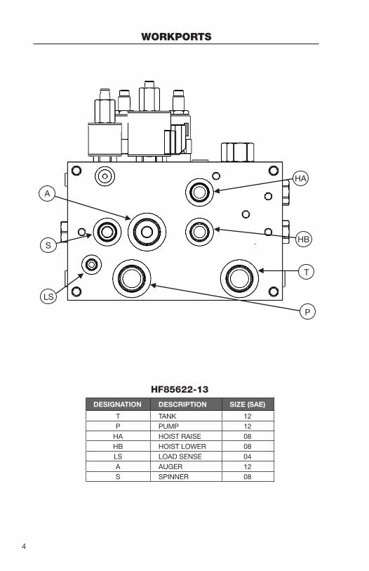
WORKPORTS
P
T
HBS
A
HA
LS
DESIGNATION DESCRIPTION SIZE (SAE)
T TANK 12P PUMP 12
HA HOIST RAISE 08HB HOIST LOWER 08LS LOAD SENSE 04A AUGER 12S SPINNER 08
HF85622-13

5
CARTRIDGE DESIGNATIONS AND PART NUMBERS
DESIGNATION P/N FUNCTION
CP1 6103008 CAVITY PLUGCB1 SUN 6114189.30 COUNTER BALANCE
CV1 – CV7 NXCV08-20-0-N-04 CHECK VALVESEP1 – EP4 NXEP10-S35-0-N-10 POST COMPENSATOR
EPFR EPFR52-S35T-0-N-240 UNLOADER COMPENSATOROR1, OR3, OR4, OR5 6101025 ORIFICE
OR2 6101000 ORIFICEOR6 6101030 ORIFICERV1 NXRV08-20A-0-N-33/18 MAIN RELIEFRV2 NXRV08-20A-0-N-09/ HOIST DOWNSIDE RELIEFRV3 NXRV10-22A-0-N-25/2.5 SPREADER RELIEFSP1 NXSP10-20M-0-N-00 AUGER FLOW CTRLSP2 NXSP08-20M-0-N-00 SPINNER FLOW CTRLSP4 NXHSP10-47C-0-U-00 HOIST CTRL
* COIL P/N: NX4303712** COIL P/N: NX4303612
SP1
RV2
SP2
SP4CP1
OR5
CV7
CV6
CV4
CV5
CV3
EP3
EP4
RV3
RV1
OR1
EP1
OR6
CV1EP2
OR2
EPFR1CB1
CV2
OR3
OR4

6
SCHEMATICOpen Center Configuration

7
RELIEF VALVE ADJUSTMENTS
Main System Relief (Factory Setting 2,500 PSI) – RV1
1. The tools required for adjusting the main relief setting includes: ¾" wrench and a ¼" Allen drive.
2. Tee a pressure gauge into the pump port (gauge greater than 3,000 PSI)
3. Loosen the lock nut while holding the Allen screw stationary.
4. Start the truck and deadhead flow at either the auger or spinner.
(Pressure will increase to the main relief setting)
5. While observing the pressure gauge, turn the Allen screw CCW to decrease pressure, and CW to increase pressure.
* DO NOT EXCEED 3000 PSI
6. Once the desired pressure has been established, hold the Allen screw stationary and tighten the lock nut.
Downside Hoist Relief (Factory Setting 950 PSI) – RV2
1. The tools required for adjusting the hoist downside relief setting includes: ¾" wrench and a ¼" Allen drive.
2. Tee a pressure gauge into the hoist lower (HB) port (Gauge greater than 1,000 PSI)
3. Loosen the lock nut while holding the Allen screw stationary.
4. Start the truck and deadhead the hoist down. (Pressure will increase to the downside relief setting)
5. While observing the pressure gauge, turn the Allen screw CCW to decrease pressure, and CW to increase pressure.
6. Once the desired pressure has been established, hold the Allen screw stationary and tighten the lock nut.
RV1
RV2
RV3

8
MANUAL OVERRIDE INSTRUCTIONS
SP1 & SP2 – Spinner/Auger
1. To manually override SP1 or SP2: Push the red override down and turn CCW. (Up Position)
2. To disengage SP1 or SP2: Push the red override down and turn CW. (Down Position)
Normal Operation: Push down and turn CW
SP4 - Hoist
1. To manually override SP4: To shift the valve manually from neutral to activate S1 (Lower the Hoist), push the knob down slight, rotate 90 degrees counterclockwise, then pull. To lock in this position, rotate the knob an additional 90 degrees counterclockwise.
To shift manually to activate S2 (Raise the Hoist), push the knob down all the way. To lock in this position, rotate the knob 90 degrees clockwise to lock in the lower detent groove.

9
CONVERTING MANIFOLD FROM OPEN-CENTER TO LOAD SENSE
Instructions:
1. Remove EPFR1 and replace with NXCP10-S30-N
2. Remove the OR2 SAE plug.
3. Remove the set-screw that is sitting inside of the OR2 cavity
4. Replace the setscrew with P/N: NX6101025
5. Reinstall the OR2 SAE plug.
6. Locate the LS port on the manifold and route back to the variable displacement pump.
OR2
EPFR1

10
TROUBLESHOOTING
SYMPTOM POSSIBLE CAUSE
Either the auger or spinner operates
wide open.
• Check manual overrides of SP1 or SP2 (Reference pg. 8 for manual override instructions) – disengage if necessary.
• Remove SP1 or SP2 from manifold and inspect cavity and cartridge for contamination.
Either the auger or spinner are inoperative.
• Inspect wiring and check continuity of Deutsch connector into solenoid receptacle.
• Verify that the flow is not bypassing motor (loss of efficiency).
• Verify that the SP1 or SP2 are magnetizing when energized.
No function operates, System
doesn’t build pressure.
• Remove EPFR from manifold and inspect cavity and cartridge for contamination.
• Check main relief (RV1) for contamination.
• Verify that pump is producing flow.
The hoist will not operate.
• Inspect plumbing – verify that the HA port is connected to the cap side of the cylinder and HB is connected to the rod of the cylinder.
• Inspect Wiring
• Increase the main relief pressure setting (pg. 7)
Manifold operates continuously at main relief pressure (1800
PSI).
• Inspect plumbing – If applicable, check quick disconnects.
• Remove EPFR from manifold and inspect cavity and cartridge for contamination.
Chattering noise occurs while system
is bypassing fluid and goes away when spreader
system is active or higher RPM’s.
• This is due to the EPFR becoming unstable at low flow conditions.
1.Try downsizing the inlet hose to a minimum of a -8 (1/2") running from the pump outlet to the manifold.
2.Downsize ORF6 from a 0.04" orifice to 0.025" orifice. Contact Muncie Power for more details.
Hoist will not lower
• Adjust counterbalance.


201 East Jackson Street • Muncie, Indiana 47305800-367-7867 • Fax 765-284-6991
[email protected] • www.munciepower.comSpecifications are subject to change without notice.
Visit www.munciepower.com for warranties and literature.All rights reserved. © Muncie Power Products, Inc. (2014)
Member of the Interpump GroupIN14-07 (Rev. 03-17)