hf nat (etops flight)
DESCRIPTION
All about HF on the NAT airspaceETOPS flightTRANSCRIPT

NAT Doc 003
North Atlantic Systems Planning Group Aeronautical Communications Group
Version 1.0September 2003
High Frequency Management
Guidance MaterialFor the
North Atlantic Region

HF Management Guidance Material
30/09/03 NATSPG ACG Page 2
Document identification
Reference: /tt/file_convert/5464b94baf795969458b4767/document.doc
Title: HF Frequency Management Guidance Material
Edited by: ACG
Editor: Jose Joaquim Cabral
Date: 30 September 2003
Published by: NATSPG
Contact: Núcleo de Procedimentos e Padrões Operacionais do Atlântico (POPATL)Aeroporto de Santa Maria9580 Vila do PortoPhone: +351 296820510Fax: +351 296820552Email: [email protected]
Obs:
document.doc

HF Management Guidance Material
30/09/03 NATSPG ACG Page 3
Table of Contents
DOCUMENT IDENTIFICATION....................................................................................................................... 2
TABLE OF CONTENTS................................................................................................................................... 3
CHANGE RECORD.......................................................................................................................................... 5
PREFACE......................................................................................................................................................... 7
LIST OF ACRONYMS...................................................................................................................................... 8
1 INTRODUCTION.................................................................................................................................... 10
1.1 PURPOSE OF THE DOCUMENT............................................................................................................10
2 OPERATIONAL CONCEPT...................................................................................................................11
2.1 OVERVIEW........................................................................................................................................ 112.2 HF MEDIUM CHARACTERISTICS...........................................................................................................112.3 RADIOTELEPHONY NETWORK.............................................................................................................122.3.1 DEFINITION................................................................................................................................... 122.3.2 NAT RADIOTELEPHONY NETWORK COMPOSITION...........................................................................122.3.3 PRINCIPLES OF NETWORK OPERATION...........................................................................................132.3.4 FREQUENCIES TO BE USED............................................................................................................132.3.5 ESTABLISHMENT OF COMMUNICATIONS...........................................................................................142.3.6 TRANSFER OF COMMUNICATIONS....................................................................................................142.3.7 COMMUNICATIONS FAILURE............................................................................................................152.4 SELCAL OPERATION........................................................................................................................ 15
3 NAT FAMILIES AND FREQUENCIES ALLOTMENT PLAN..................................................................16
3.1 FREQUENCY ALLOTMENT PLAN FOR THE AERONAUTICAL MOBILE SERVICE (AMS)...............................163.1.2 MAJOR WORLD AIR ROUTE AREA – NORTH ATLANTIC (MWARA - NAT).........................................163.1.3 MWARA – NAT FREQUENCIES.....................................................................................................163.1.4 NAT FAMILIES.............................................................................................................................. 173.1.5 NAT SUB-NETWORKS.................................................................................................................... 17
4 NAT FAMILIES AND FREQUENCIES ALLOCATION PRINCIPLES....................................................19
4.1 GENERAL PRINCIPLES........................................................................................................................ 194.2 FAMILY ALLOCATION PRINCIPLES........................................................................................................194.2.1 FAMILY A OR SUB-NETWORK A......................................................................................................194.2.2 FAMILY B AND C OR SUB-NETWORKS B AND C...............................................................................204.2.3 FAMILY D OR SUB-NETWORK D......................................................................................................204.2.4 FAMILY E OR SUB-NETWORK E......................................................................................................204.2.5 FAMILY F OR SUB-NETWORK F......................................................................................................214.3 FREQUENCY ALLOCATION PRINCIPLES................................................................................................21
5 GENERAL NOTES................................................................................................................................. 23
5.1 HOURS OF SERVICE........................................................................................................................... 235.2 POINTS OF CONTACT......................................................................................................................... 235.3 COORDINATION PRINCIPLES...............................................................................................................23
document.doc

HF Management Guidance Material
30/09/03 NATSPG ACG Page 4
APPENDIX A - HF MEDIUM CHARACTERISTICS......................................................................................25
APPENDIX B-1 - BODO RADIO STATION INFORMATION........................................................................29
APPENDIX B-2 - GANDER RADIO STATION INFORMATION.....................................................................30
APPENDIX B-3 - ICELAND RADIO STATION INFORMATION....................................................................31
APPENDIX B-4 - NEW YORK RADIO STATION INFORMATION................................................................32
APPENDIX B-5 - SANTA MARIA RADIO STATION INFORMATION...........................................................33
APPENDIX B-6 - SHANWICK RADIO STATION INFORMATION................................................................34
APPENDIX C-1 - BODO RADIO STATION FREQUENCIES HOURS OF SERVICE...................................35
APPENDIX C-2 - GANDER RADIO STATION FREQUENCIES HOURS OF SERVICE................................36
APPENDIX C-3 - ICELAND RADIO STATION FREQUENCIES HOURS OF SERVICE...............................37
APPENDIX C-4 - NEW YORK RADIO STATION FREQUENCIES HOURS OF SERVICE...........................38
APPENDIX C-5 - SANTA MARIA RADIO STATION FREQUENCIES HOURS OF SERVICE.....................39
Appendix C-6 - SHANWICK Radio Station Frequencies Hours of Service....................................................40
document.doc

HF Management Guidance Material
30/09/03 NATSPG ACG Page 5
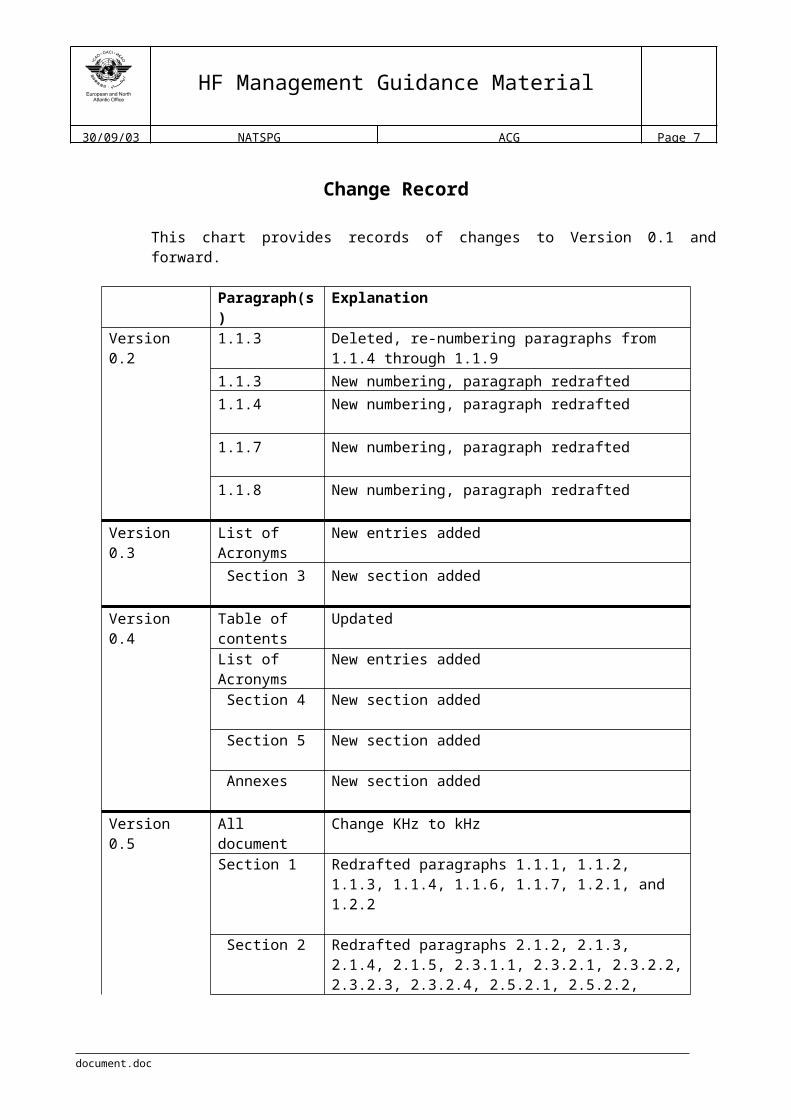
Change Record
This chart provides records of changes to Version 0.1 and forward.
Paragraph(s) Explanation
Version 0.2 1.1.3 Deleted, re-numbering paragraphs from 1.1.4 through 1.1.91.1.3 New numbering, paragraph redrafted1.1.4 New numbering, paragraph redrafted
1.1.7 New numbering, paragraph redrafted
1.1.8 New numbering, paragraph redrafted
Version 0.3 List of Acronyms
New entries added
Section 3 New section added
Version 0.4 Table of contents
Updated
List of Acronyms
New entries added
Section 4 New section added
Section 5 New section added
Annexes New section added
Version 0.5 All document Change KHz to kHz
Section 1 Redrafted paragraphs 1.1.1, 1.1.2, 1.1.3, 1.1.4, 1.1.6, 1.1.7, 1.2.1, and 1.2.2
Section 2 Redrafted paragraphs 2.1.2, 2.1.3, 2.1.4, 2.1.5, 2.3.1.1, 2.3.2.1, 2.3.2.2, 2.3.2.3, 2.3.2.4, 2.5.2.1, 2.5.2.2, 2.5.2.3, and 2.5.4.1.Removed references to Annex 10 in 2.3.3, 2.3.4, 2.3.5, 2.3.6, 2.3.7, and 2.4.Removed 2.5.2.3
Section 3 Redrafted paragraphs 3.1.3.1, 3.1.4.1, 3.1.4.2, 3.1.4.3, 3.1.5.1, 3.2.1, 3.2.2.4.1, 3.2.2.5.1 and 3.2.2.5.2.
Section 4 Redrafted paragraphs 4.1.1, 4.1.4, 4.1.5, 4.1.6, 4.1.7, 4.2.1.1, 4.2.1.2, 4.2.1.3, 4.2.2.1, 4.2.2.2, 4.2.2.3, 4.2.3.1, 4.2.3.2, 4.2.3.3, 4.2.4.1, 4.2.4.2, 4.2.4.3, 4.2.5.1, 4.2.5.2, 4.2.6.1, 4.2.6.2, 4.2.6.3, 4.3.1, 4.3.2, 4.3.3 and 4.3.4.New paragraphs 4.2.2.4, 4.2.3.4 and 4.3.5
document.doc

HF Management Guidance Material
30/09/03 NATSPG ACG Page 6
Paragraph(s) Explanation
Section 5 Redrafted paragraphs 5.1.2, 5.2.1, 5.3.1, 5.3.2 and 5.4.1
Annexes Updated
Version 0.6 Table of contents
Update. Removed references to VOLMET
Section 1 Removed references to VOLMET on 1.2.2
Section 2 Review 2.2, correction on 2.3.2.2, removed references to VOLMET on 2.2.4 – Table 1, delete 2.5
Section 3 Correction on 3.1.5.1, delete 3.2
Section 4 Redrafted 4.2.2. Deleted 4.2.3. Renumbering of 4.2.3 to 4.2.6
Section 5 Reviewed 5.1, 5.2, and 5.3, delete 5.4.
Appendixes Renamed to Appendixes. New section format. New Appendix A. Delete old Annexes 7, 8 and 9 related to VOLMET Broadcast Plan.
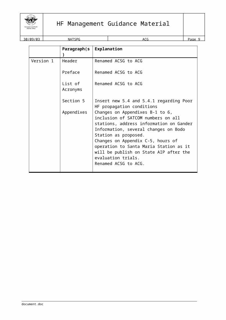
Version 1 Header Renamed ACSG to ACG
Preface Renamed ACSG to ACG
List of Acronyms
Renamed ACSG to ACG
Section 5 Insert new 5.4 and 5.4.1 regarding Poor HF propagation conditions
Appendixes Changes on Appendixes B-1 to 6, inclusion of SATCOM numbers on all stations, address information on Gander Information, several changes on Bodo Station as proposed.Changes on Appendix C-5, hours of operation to Santa Maria Station as it will be publish on State AIP after the evaluation trials.Renamed ACSG to ACG.
document.doc
HF Management Guidance Material
30/09/03 NATSPG ACG Page 7
Preface
This Document is published by the North Atlantic Systems Planning Group, and managed by the Aeronautical Communications Group, and is for guidance. Regulatory material relating to North Atlantic communications procedures is contained in relevant ICAO Documents and Annexes. Annex 10 – Volume II, ITU Radio Regulations, Regional Supplementary Procedures (Doc. 7030), FASID, NAT OPS Manual, State AIP and current NOTAM’s, which should be read in conjunction with the guidance material contained in this document.
To assist with the editing of this document and to ensure the currency and accuracy of future editions, comments and suggestions for possible amendments should be sent to the editor, to the contact information included in the document identification section.
document.doc

HF Management Guidance Material
30/09/03 NATSPG ACG Page 8
List of Acronyms
ACARS Aircraft Communication Addressing and Reporting SystemACC Area Control CentreACG Aeronautical Communications GroupACID Aircraft IdentificationAIP Aeronautical Information PublicationAFTN Aeronautical Fixed Telecommunication NetworkAMS Aeronautical Mobile ServiceARINC Aeronautical Radio INC.ARP Air Report MessageATC Air Traffic ControlATM Air Traffic ManagementATN Aeronautical Telecommunication NetworkATS Air Traffic ServicesATSMP Air Traffic Services Message ProcessorATSU Air Traffic Services UnitCAA Civil Aviation AuthorityCNS Communications, Navigation and SurveillanceEMG Emergency MessageFAP Frequency Allotment PlanFDPS Flight Data Processing SystemFIR Flight Information RegionFMC Flight Management ComputerFMS Flight Management SystemGP General PurposeGPS Global Positioning SystemHF High Frequency (3 to 30 MHz)ICAO International Civil Aviation OrganizationICD Interface Control DocumentITU International Telecommunications UnionLDOC Long Distance Operations ControlkHz KilohertzLF Low Frequency (30 to 300 kHz)LUF Lowest Usable Frequency MET MeteorologicalMF Medium Frequency (300 to 3000 kHz)MHz MegahertzMUF Maximum Usable FrequencyMWAR Major World Air RouteMWARA Major World Air Route AreaNAT North AtlanticNAT SPG North Atlantic Systems Planning GroupNOTAM Notice to AirmenOCA Oceanic Control Area
document.doc
HF Management Guidance Material
30/09/03 NATSPG ACG Page 9
POS ICAO Position Report MessageRDAR Regional and Domestic Air RoutesRDARA Regional and Domestic Air Route AreaR/T Radio-TelephonySARPS Standards and Recommended PracticesSELCAL Selective Calling SystemVHF Very High Frequency (30 to 300 MHz)VLF Very Low Frequency (3 to 30 kHz)WP Waypoint PositionWPR Waypoint Position Reporting
document.doc
HF Management Guidance Material
30/09/03 NATSPG ACG Page 10
1 Introduction
1.1 Purpose of the document
1.1.1 The purpose of this document is to provide a guidance methodology for the utilisation of the Families and Frequencies employed by the Aeronautical Communication Stations on the North Atlantic, to support a better management plan of the available families, frequencies and human resources, in order to increase the efficiency and capacity of the Communications Network.
1.1.2 It will also include information about HF frequencies for air-ground communications. In addition, it will contain contact information for Aeronautical Stations.
document.doc

HF Management Guidance Material
30/09/03 NATSPG ACG Page 11
2 Operational concept
2.1 Overview
2.1.1 The Aeronautical Mobile Service is a service reserved for air-ground communications related with the safety and regularity of flights, flying primarily along national or international civil air routes.
2.1.2 In areas like the North Atlantic, where VHF coverage is insufficient due to range limitation to cover all portions of the routes flown, the use of HF frequencies are necessary because they provide long range communications coverage, not only for air-ground voice communications, but also for the broadcast of ATS or Meteo information.
2.1.3 For various reasons, some technical, others economical, environmental, physical, natural, etc., coverage of a wide area by a single station with equipment located in a single place are impractical.
2.1.4 Taking these factors into account, the most practical option is to employ a number of stations sharing a range of frequencies and working as a network to provide the facilities and services required for the AMS.
2.1.5 To work as a network the AMS should follow appropriate principles of operation, in order to achieve the highest possible level of capacity and efficiency, otherwise, its purpose will not be achieved and the safety and regularity of flights will be affected.
2.2 HF medium characteristics
2.2.1 This section presents only a short description on the HF medium characteristics, a more detail description can be found in Appendix A.
2.2.2 As a general rule, radio signals travel in straight lines, that is, they follow great circle paths over the surface of the earth. Under certain circumstances, however, the path of a signal may change direction, this change of direction is called refraction. Refraction examples are coastal, atmospheric and ionospheric, and the amount of refraction varies considerably, depending on certain conditions. Those conditions could be a change in direction when a signal crosses a coastline (coastal refraction), a change in direction due to a variation in temperature, pressure and humidity, particularly at low altitude (atmospheric refraction), or a change in direction when the radio wave passes through an ionised layer (ionospheric refraction).
2.2.3 The ionosphere is still under investigation but it is known that several definite ionised layers exist within it. During daytime hours there are four main ionisation layers designated D, E, F1 and F2 in ascending order of height. At night, when the sun’s radiation is absent, ionisation still persists but it is less intense, and fewer layers are found (D and F layers). Factors that affect the ionosphere layers is strength of the sun’s radiation, since it varies with latitude causing that the structure of the ionosphere varies widely over the earth’s
document.doc

HF Management Guidance Material
30/09/03 NATSPG ACG Page 12
surface, and the state of the sun, since sunspots affect the amount of ultra-violet radiation.
2.2.3.1 Maximum Usable Frequency (MUF) at night is much less than by day, because the intensity of ionisation in the layer is less so than lower frequencies have to be used to produce the same amount of refractive bending and give the same critical angle and skip distance as by day. However, the signal attenuation in the ionosphere is also much less at night so the lower frequency needed is still usable. Hence the night frequency for a given path is about half of the day frequency, and shorter distances can be worked at night than by day while still using a single reflection from the F layer.
2.2.3.2 The MUF not only varies with path length and between day and night, but also with season, meteor trails, sunspot state, and sudden ionospheric disturbances produced by eruptions on the sun. Because of the variations of MUF, HF transmitting stations have to use frequencies varying widely between about 2 and 20 MHz.
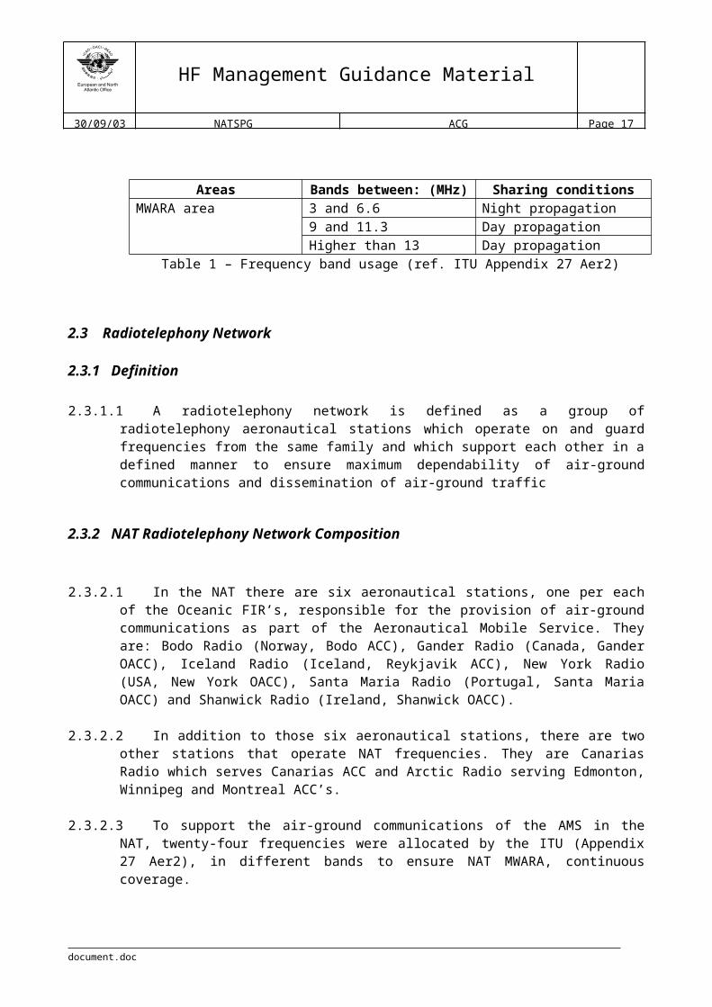
2.2.4 As consequence of this conditions, frequency band usage can be viewed in the following table:
Areas Bands between: (MHz) Sharing conditionsMWARA area 3 and 6.6 Night propagation
9 and 11.3 Day propagationHigher than 13 Day propagation
Table 1 – Frequency band usage (ref. ITU Appendix 27 Aer2)
2.3 Radiotelephony Network
2.3.1 Definition
2.3.1.1 A radiotelephony network is defined as a group of radiotelephony aeronautical stations which operate on and guard frequencies from the same family and which support each other in a defined manner to ensure maximum dependability of air-ground communications and dissemination of air-ground traffic
2.3.2 NAT Radiotelephony Network Composition
2.3.2.1 In the NAT there are six aeronautical stations, one per each of the Oceanic FIR’s, responsible for the provision of air-ground communications as part of the Aeronautical Mobile Service. They are: Bodo Radio (Norway, Bodo ACC), Gander Radio (Canada, Gander OACC), Iceland Radio (Iceland, Reykjavik ACC), New York Radio (USA, New York OACC), Santa Maria Radio (Portugal, Santa Maria OACC) and Shanwick Radio (Ireland, Shanwick OACC).
2.3.2.2 In addition to those six aeronautical stations, there are two other stations that operate NAT frequencies. They are Canarias Radio which serves Canarias ACC and Arctic Radio
document.doc

HF Management Guidance Material
30/09/03 NATSPG ACG Page 13
serving Edmonton, Winnipeg and Montreal ACC’s.
2.3.2.3 To support the air-ground communications of the AMS in the NAT, twenty-four frequencies were allocated by the ITU (Appendix 27 Aer2), in different bands to ensure NAT MWARA, continuous coverage.
2.3.2.4 All NAT HF frequencies are organized into six groups known as Families, The families are identified as NAT Family A, B, C, D, E and F. Each Family contains a range of frequencies from each of the HF frequency bands allocated to the Network.
2.3.3 Principles of Network Operation
2.3.3.1 The aeronautical stations of a radiotelephony network should assist each other in order to provide the air-ground communication service required of the network by aircraft flying on the air routes for which the network is responsible.
2.3.3.2 When the network comprises a large number of stations, network communications for flights on any individual route segment should be provided by selected stations, termed “regular stations” for that segment. In principle, the regular station will be those serving the locations immediately concerned with flights on that route segment, i.e. points of take-off and landing and appropriate flight information centres or area control centres.
2.3.3.3 In areas or on routes where radio conditions, length of flights or distance between aeronautical stations require additional measures to ensure continuity of air-ground communications throughout the route segment, the regular stations should share between them a responsibility of primary guard whereby each station will provide the primary guard for that portion of the flight during which the messages from the aircraft can be handled most effectively by that station.
2.3.3.4 During its tenure of primary guard, each regular station should, among other things:
a) be responsible for designating suitable primary and secondary frequencies for its communications with the aircraft;
b) receive all position reports and handle other messages from and to the aircraft essential to the safe conduct of the flight;
c) be responsible for the action required in case of failure of communication.
2.3.4 Frequencies to be used
2.3.4.1 Aircraft stations shall operate on the appropriate radio frequencies.
2.3.4.2 The air-ground radio station shall designate the frequency(ies) to be used under normal conditions by aircraft stations operating under its control.
2.3.4.3 In network operation, the initial designation of primary and secondary frequencies should be made by the network station with which the aircraft makes pre-flight check or its initial
document.doc

HF Management Guidance Material
30/09/03 NATSPG ACG Page 14
contact after take-off. This station should also ensure that other network stations are advised, as required, of the frequency(ies) designated.
2.3.4.4 An aeronautical station when designating frequencies, should take into account the appropriate propagation data and distance over which communications are required .
2.3.4.5 If a frequency designated by an aeronautical station proves to be unsuitable, the aircraft station should suggest an alternative frequency.
2.3.5 Establishment of communications
2.3.5.1 Aircraft stations shall, if possible, communicate directly with the air-ground control radio station appropriate to the area in which the aircraft are flying. If unable to do so, aircraft stations shall use any relay means available and appropriate to transmit messages to the air-ground control radio station.
2.3.5.2 When normal communications from an aeronautical station to an aircraft station cannot be established, the aeronautical station shall use any relay means available and appropriate to transmit messages to the aircraft station. If this efforts fail, the originator shall be advised.
2.3.5.3 When, in network operation, communication between an aircraft station and a regular station has not been established after calls on the primary and secondary frequencies, aid should be rendered by one of the other regular stations for that flight, either by calling the attention of the station first called or, in case of a call made by an aircraft station, by answering the call and taking the traffic.
2.3.5.4 Other stations of the network should render assistance by taking similar action only if attempts to establish communication by the regular stations have proved unsuccessful.
2.3.6 Transfer of communications
2.3.6.1 The transfer of primary guard from one station to the next will normally take place at the time of the traversing of flight information region or control area boundaries, this guard being provided at any time, as far as possible, by the station serving the flight information centre or area control centre in whose area the aircraft is flying.
2.3.6.2 An aircraft station should be advised by the appropriate aeronautical station to transfer from one radio frequency or network to another. In the absence of such advice, the aircraft station should notify the appropriate aeronautical station before such transfer takes place.
2.3.6.3 In the case of transfer from one network to another, the transfer should preferably take place while the aircraft is in communication with a station operating in both networks to ensure continuity of communications. If, however, the change of network must take place concurrently with the transfer of communication to another network station, the transfer should be co-ordinated by the two network stations prior to advising or authorizing the
document.doc

HF Management Guidance Material
30/09/03 NATSPG ACG Page 15
frequency change. The aircraft should also be advised of the primary and secondary frequencies to be used after the transfer.
2.3.7 Communications failure
2.3.7.1 When an aircraft station fails to establish contact with the aeronautical station on the designated frequency, it shall attempt to establish contact on another frequency appropriate to the route. If this attempt fails, the aircraft station shall attempt to establish communication with other aircraft or other aeronautical stations on frequencies appropriate to the route. In addition, an aircraft operating within a network shall monitor the appropriate VHF frequency for calls from nearby aircraft.
2.3.7.2 When an aeronautical station has been unable to establish contact with an aircraft station after calls on the frequencies on which the aircraft is believed to be listening, it shall:
a) Request other aeronautical stations to render assistance by calling the aircraft and relaying traffic, if necessary;
b) Request aircraft on the route to attempt to establish communication with the aircraft and relay traffic, if necessary.
2.3.7.3 The air-ground control radio station shall notify the appropriate air traffic services unit and the aircraft operating agency, as soon as possible, of any failure in air-ground communications.
2.4 SELCAL operation
2.4.1 With the selective calling system known as SELCAL, the voice call is replaced by the transmission of coded tones to the aircraft over the radiotelephony channels. A single selective call consists of a combination of four pre-selected audio tones whose transmission requires approximately two seconds. The tones are generated in the aeronautical station coder and are received by a decoder connected to the audio output of the airborne receiver. Receipt of the assigned tone code activates a cockpit call system in the form of light and/or chime signals.
document.doc
HF Management Guidance Material
30/09/03 NATSPG ACG Page 16
3 NAT Families and Frequencies Allotment Plan
3.1 Frequency Allotment Plan for the Aeronautical Mobile Service (AMS)
3.1.1 The frequencies allocated for use in the NAT, are based on the Frequency Allotment Plan, for the MWARA - NAT as defined on the “Appendix 27 Aer2 to the Radio Regulations – Frequency Allotment Plan for the Aeronautical Mobile (R) Service and Related Information”.
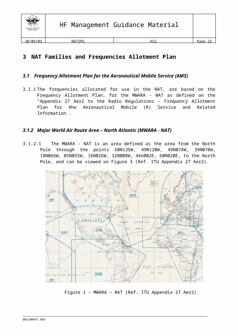
3.1.2 Major World Air Route Area – North Atlantic (MWARA - NAT)
3.1.2.1 The MWARA - NAT is an area defined as the area from the North Pole through the points 60N135W, 49N120W, 49N074W, 39N078W, 18N066W, 05N055W, 16N026W, 32N008W, 44n002E, 60N020E, to the North Pole, and can be viewed on Figure 3 (Ref. ITU Appendix 27 Aer2).
Figure 1 – MWARA – NAT (Ref. ITU Appendix 27 Aer2)
3.1.3 MWARA – NAT Frequencies
3.1.3.1 The frequencies allocated to the MWARA – NAT includes a number of frequencies in a range of bands designed to provide twenty-four hour area coverage and are contained in Table 2.
document.doc
HF Management Guidance Material
30/09/03 NATSPG ACG Page 17
Frequency BandsArea 3 3.5 4.7 5.6 6.6 9 11.3 13.3 18
kHz kHz kHz kHz kHz kHz kHz kHz kHz2872 3476 4675 5598 6622 8825 11279 13291 179462899 5616 6628 8831 11309 13306
NAT 2962 5649 8864 11336 13354*2971 88793016 8891
8906* Frequency shared with RDARA 5 and 7
Table 2 – Frequency bands of FAP for the MWARA – NAT (Ref. ITU Appendix 27 Aer2)
3.1.4 NAT Families
3.1.4.1 The NAT Families were defined utilising the frequencies allocated for the purpose of providing an AMS throughout the coverage area required.
3.1.4.2 Each Family comprises a range of frequencies drawn from each frequency band and selected in such a way as to provide, to the extent possible, continuous service in the area of responsibility at all times of day and under varying propagation conditions.
3.1.4.3 The organisation of the NAT HF Families and corresponding frequencies are contained in Table 3.
NAT Family FrequenciesA 3016, 5598, 8906, 13306 and 17946 kHzB 2899, 5616, 8864, 13291 and 17946 kHzC 2872, 5649, 8879, 11336, 13306 and 17946 kHzD 2971, 4675, 8891, 11279, 13291 and 17946 kHzE 2962, 6628, 8825, 11309, 13354 and 17946 kHzF 3476, 6622, 8831, 13291 and 17946 kHz
Frequency 13306 kHz is shared between Families A and CFrequency 13291 kHz is shared between Families, B, D and FFrequency 17946 kHz is shared by all the FamiliesFrequency 13354 kHz is shared with RDARA 5 and 7
Table 3 – NAT families and frequencies
3.1.5 NAT Sub-networks
3.1.5.1 Based on the definition of a radiotelephony network as described in paragraph 2.3.1.1 above, the NAT Radiotelephony Network comprises six sub-networks, one per each of the NAT Families. These sub-networks are described in Table 4.
document.doc

HF Management Guidance Material
30/09/03 NATSPG ACG Page 18
NAT Family Sub-network Stations
A A
Gander Radio New York RadioSanta Maria RadioShanwick Radio
B BGander RadioIceland RadioShanwick Radio
C C
Gander RadioIceland RadioShanwick Radio
D D
Bodo RadioGander RadioIceland RadioShanwick RadioArctic Radio (*)
E ECanarias Radio (**)New York RadioSanta Maria Radio
F FGander RadioShanwick Radio
(*) Artic Radio is not a NAT Station.(**) Canarias Radio is not a NAT Station. Included as interface between NAT and AFI
Table 4 – NAT Sub-networks
document.doc
HF Management Guidance Material
30/09/03 NATSPG ACG Page 19
4 NAT Families and Frequencies Allocation Principles
4.1 General principles
4.1.1 In accordance with the principles of network operation, as described in paragraph 2.3.3, the frequencies assigned to an aircraft should belong to the same sub-network, which includes all the stations that may be affected by the aircraft flight route.
4.1.2 The frequency assignment should always take into account the propagation conditions, route of flight, distance from station, possible affected stations and even distribution over network frequencies, especially during peak periods.
4.1.3 Frequency assignment should, whenever possible, be done in such a way that radio stations could take advantage of all the available operational frequencies, and thereby avoid or shorten the delay time usually associated with the current system.
4.1.4 Frequencies should be guarded only during the periods when they are usable, as described in paragraph 2.2, instead of maintaining the current twenty-four hour watch practice.
4.1.5 During off-peak periods, when it is unnecessary to guard all frequencies and families, radio stations should use common families to achieve more efficient use of staff resources.
4.1.6 There should be regular tactical co-ordination of network resources between sub-network stations to meet changing operational requirements.
4.1.7 Stations experiencing peak demand should, following co-ordination with other network stations, be facilitated in sharing available network frequencies.
4.2 Family allocation principles
4.2.1 Family A or Sub-network A
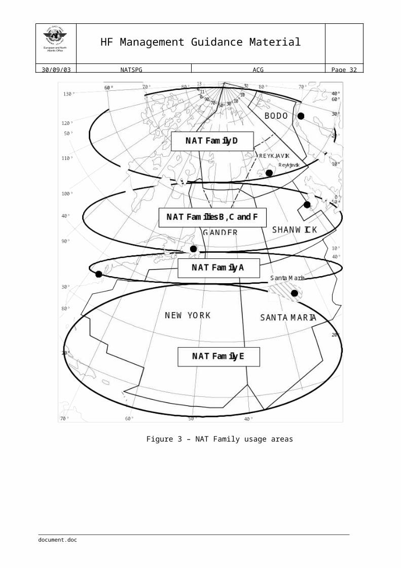
4.2.1.1 This family should, whenever possible, be assigned to aircraft whose route or portion of route transits Gander, New York, Santa Maria and Shanwick areas, especially those aircraft flying routes with reporting point coordinates between 43N and 47N.
4.2.1.2 Stations should not assign Family A to aircraft flying routes outside the area defined in 4.2.1.1, due to overloading of other families or for other operational reasons, without prior co-ordination with and agreement of other sub-network stations in order to minimise adverse impact on existing sub-network traffic.
4.2.1.3 During off peak periods, and when watch is reduced on other families, Family A should remain the primary assignment for aircraft flying southerly routes.
document.doc

HF Management Guidance Material
30/09/03 NATSPG ACG Page 20
4.2.2 Family B and C or Sub-networks B and C
4.2.2.1 This Family should, whenever possible, be assigned to aircraft flying on eastbound or westbound tracks whose route or portion of route lies within the Gander, Iceland and Shanwick areas, particularly aircraft flying routes with reporting point coordinates between 47N and 64N.
4.2.2.2 Stations should not assigned Family B and C to aircraft flying routes outside the area defined in 4.2.2.1, due to overloading of other families or for other operational reasons, without prior co-ordination with and agreement of the other sub-network stations in order to minimise adverse impact on existing sub-network traffic.
4.2.2.3 At all times Family B and C should remain the primary assignment for aircraft flying central routes.
4.2.2.4 In order to ensure even peak-time distribution of traffic between Family B and C, aircraft may be assigned to either family on the basis of; state of registry, Airline Company or other such criteria as agreed between Shanwick Radio and Gander Radio.
4.2.3 Family D or Sub-network D
4.2.3.1 This Family should, whenever possible, be assigned to aircraft whose route or portion of route lies within the Bodo, Gander, Iceland and Shanwick areas, particularly those aircraft flying routes with reporting point coordinates north of 62N.
4.2.3.2 Stations should not assign Family D to aircraft flying routes outside the area defined in 4.2.3.1, due to overloading of other families or for other operational reasons, without prior co-ordination with and agreement of other sub-network stations in order to minimise adverse impact on existing sub-network traffic.
4.2.3.3 During off peak periods, and when watch is reduced on other families, Family D should remain the primary assignment for aircraft flying northerly routes.
4.2.4 Family E or Sub-network E
4.2.4.1 This Family should, whenever possible, be assigned to aircraft whose route or portion of route transits New York and Santa Maria areas, especially those aircraft flying routes with reporting point coordinates south of 43N.
4.2.4.2 Stations should not assign Family E to aircraft flying routes outside the area defined in 4.2.4.1, due to overloading of other families or for other operational reasons, without prior co-ordination with and agreement of other sub-network stations in order to minimise adverse impact on existing sub-network traffic.
4.2.4.3 During off peak periods, and in the case of reduction of the number of available families, the guard of this family should be discontinued.
document.doc

HF Management Guidance Material
30/09/03 NATSPG ACG Page 21
4.2.5 Family F or Sub-network F
4.2.5.1 This Family should, whenever possible, be assigned to aircraft flying routes entirely within the Gander and Shanwick areas.
4.2.5.2 Stations should not assign Family F to aircraft flying routes outside the area defined in 4.2.5.1, due to overloading of other families or for other operational reasons, without prior co-ordination with and agreement of other sub-network stations in order to minimise adverse impact on existing sub-network traffic.
4.2.5.3 Hours of operation of Family F shall be co-ordinated on a tactical basis between Shanwick Radio and Gander Radio.
4.3 Frequency allocation principles
4.3.1 Taking into account the characteristics of the HF medium, the general principles for frequency assignment used by radio station personnel is as outlined in 2.2.4 and contained in Table 7.
Bands between: (MHz) Sharing conditions3 and 6.6 Night propagation9 and 11.3 Day propagationHigher than 13 Day propagation
Table 7 – General principles for frequency assignment
4.3.2 As a general rule, when assigning primary and secondary frequencies, radio station personnel should assign lower frequencies as primary and higher frequencies as secondary for aircraft flying away from the Station. Conversely, for aircraft routing towards the station, the higher frequencies should be assigned as primary and lower frequencies as secondary.
4.3.3 In circumstances were sunspot or solar flare activity is expected to affect propagation conditions, the radio station personnel should always inform the flight crews and in addition to assigning the primary and secondary frequencies, they should advise the highest frequencies in use at the station as a precautionary measure.
4.3.4 In accordance with the principles governing transfer of communications as defined in paragraph 2.3.6, stations sharing a common boundary should, whenever possible, assign common frequencies for the transfer of communications.
4.3.5 Aircraft routing along common boundaries, or flying a route or portion of a route within 60 NM of a common boundary, should be assigned frequencies common to the stations sharing those boundaries.
document.doc
HF Management Guidance Material
30/09/03 NATSPG ACG Page 22
Figure 3 – NAT Family usage areas
document.doc
HF Management Guidance Material
30/09/03 NATSPG ACG Page 23
5 General notes
5.1 Hours of service
5.1.1 Each station should define the frequencies hours of service, taking into account the general principles defined on paragraph 4.1.
5.1.2 The defined hours of service will be published and updated in the Annexes to this document, and can be viewed in Appendix C-1 (Bodo), Appendix C-2 (Gander), Appendix C-3 (Iceland), Appendix C-4 (New York), Appendix C-5 (Santa Maria) and Appendix C-6 (Shanwick).
5.2 Points of contact
5.2.1 Contact details of the station managers and watch supervisors for each radio station are contained in the Annexes section as follows: Appendix B-1 (Bodo), Appendix B-2 (Gander), Appendix B-3 (Iceland), Appendix B-4 (New York), Appendix B-5 (Santa Maria) and Appendix B-6 (Shanwick).
5.3 Coordination principles
5.3.1 For routine day-to-day operations such as inter-station tactical co-ordination of frequency and family assignments, network co-operation and support, etc., contact should be made with the duty supervisor/watch manager using the contact means specified in Appendixes B-1, 2, 3, 4, 5 and 6.
5.3.2 When the coordination between stations involves subjects such as procedures, institutional issues, or issues affecting the Network as a whole, etc., the contact to the station or stations should be made to the station manager through the points of contact defined in Appendixes B-1, 2, 3, 4, 5 and 6.
5.4 Poor HF propagation conditions
5.4.1 Whenever a radio station duty supervisor/watch manager have access to information or warnings regarding poor HF propagation conditions or high levels of solar activities, that will affect the normal HF operations, he should notify the on duty Supervisor of the ATC unit in which the station provide the service.
document.doc

HF Management Guidance Material
30/09/03 NATSPG ACG Page 24
Appendices
document.doc

HF Management Guidance Material
30/09/03 NATSPG ACG Page 25
Appendix A - HF medium characteristics
1.1 The term frequency is used to state the number of cycles occurring in one second, taking into account that cycle means a complete oscillation of the alternating current. The distance travelled by a radio signal during the transmission of one cycle is called wavelength. Wavelength is inversely proportional to frequency, so that if frequency is increased the wavelength will decrease.
1.2 If an alternating current of suitably high frequency is fed to a transmitting aerial, the energy is not confined to the metal of the aerial but radiates out into space in the form of electro-magnetic waves (radio waves). This radiation of energy through space comprises alternating and magnetic fields at right angles to each other.
1.3 As a general rule, radio signals travel in straight lines, that is, they follow great circle paths over the surface of the earth. Under certain circumstances, however, the path of a signal may change direction, this change of direction is called refraction. Refraction examples are coastal, atmospheric and ionospheric, and the amount of refraction varies considerably, depending on certain conditions. Those conditions could be a change in direction when a signal crosses a coastline (coastal refraction), a change in direction due to a variation in temperature, pressure and humidity, particularly at low altitude (atmospheric refraction), or a change in direction when the radio wave passes through an ionised layer (ionospheric refraction).
1.4 The path of a radio wave from a transmitter to a receiver many miles away is not necessarily direct, and in many cases, the signal may be reaching the receiver by more than one path at the same time. Because of the different path lengths there will be phase differences between the signals, and this fact will affect the resultant signal strength, phenomenon known as fading.
1.5 The main propagation paths between a transmitter and a receiver are, direct wave, ground-reflected wave, space wave, surface wave, ground wave and sky wave.
1.5.1 When a signal travels in a straight line between the transmitter and receiver it is called direct wave and its use is limited because of the earth curvature. If the radio wave arrive to the receiver after reflection at the earth’s surface it is called ground-reflected wave. These two waves are jointly known as the space wave and under normal conditions it’s the only propagation path for frequencies above 30 Mhz.
1.5.2 When a signal follows the curvature of the earth, this path is called surface wave, and is normally caused by a phenomenon called diffraction. Diffraction occurs for all types of wave motion, and allows the wave to pass round earth obstacles and depends on the wavelength in relation to the radius of the earth. The range of surface wave depends on the wavelengths, with longer wavelengths (lower frequencies) the diffraction effect becomes more pronounced with consequently improved surface wave range, the type of surface, because different surfaces absorb different amounts of radio energy resulting in different rates of attenuation, being higher over land than over sea, and the frequency used, with lower frequencies suffering less attenuation along the surface and therefore providing better surface wave range.
document.doc

HF Management Guidance Material
30/09/03 NATSPG ACG Page 26
1.5.3 The combination of direct, ground-reflected and surface waves can be described has the ground wave. However, not all of those types of waves have to be necessarily present together.
1.5.4 When signals are reflected or refracted down from ionised layers above the earth the path is called sky waves, also sometimes called ionosphere waves.
1.6 Ultra-violet light from the sun can cause electrons to become separated from their parent atoms of the gases in the atmosphere. The atoms are left with resultant positive charges and are then known as ions. The intensity of the ionisation depends on the strength of the ultra-violet radiation and the density of the air. The part of the atmosphere in which this process occurs is called the ionosphere, extending from about 50 Km to as high as 500 Km above the earth’s surface. When a radio wave enters such a layer, refraction occurs causing the wave to be bent away from its straight path. The amount of refraction depends on the frequency, the angle at which the wave enters the layer, and the intensity of ionisation.
1.7 The ionosphere is still under investigation but is known that several definite ionised layers exist within it. During daytime hours there are four main ionisation layers designated D, E, F1
and F2 in ascending order of height. At night, when the sun’s radiation is absent, ionisation still persists but it is less intense, and fewer layers are found (D and F layers). Factors that affect the ionosphere layers is strength of the sun’s radiation, since it varies with latitude causing that the structure of the ionosphere varies widely over the earth’s surface, and the state of the sun, since sunspots affect the amount of ultra-violet radiation.
1.7.1 The D layer is only significant during daylight hours, dispersing soon after sunset. It is the lowest layer and its intensity of ionisation is not great, in which VLF waves are reflected from the base of the layer, LF and MF waves enter the layer and are severely attenuated without being appreciably refracted, and higher frequency signals pass through the layer with less attenuation.
1.7.2 The E layer is strong ionised by day and remains weakly ionised by night, producing strong sky waves in the LF and MF bands by night, but during the daytime due to the attenuation caused by the D layer the sky waves produced are too weak to used in these bands. Usable HF sky waves may be produced by this layer during nigh and day, and VHF signals usually pass through this layer, and if refraction exist it is insufficient to generate sky waves, unless under “freak” conditions, duct (or super-refraction) and scatter (or sporadic-E reflections) propagation. Ionospheric refraction is negligible with UHF, SHF and EHF signals and sky waves do not occur in these bands.
1.7.3 The F layer is the highest and more intensely ionised layer. At night there is only one F layer, but during the daytime is divided into two layers, the F1 and F2. Strong sky waves are produced in the LF, MF and HF bands at night but only the HF band has usable F layer sky waves by day. Signals in the VHF and higher bands escape through the F layer into space with, normally, no sky waves produced.
1.8 Sky wave propagation in the HF band (3 to 30 MHz) is complicated, because there are many variable factors, which decide whether or not there is a propagation path open between transmitter and receiver for long-range radiotelephony.
document.doc
HF Management Guidance Material
30/09/03 NATSPG ACG Page 27
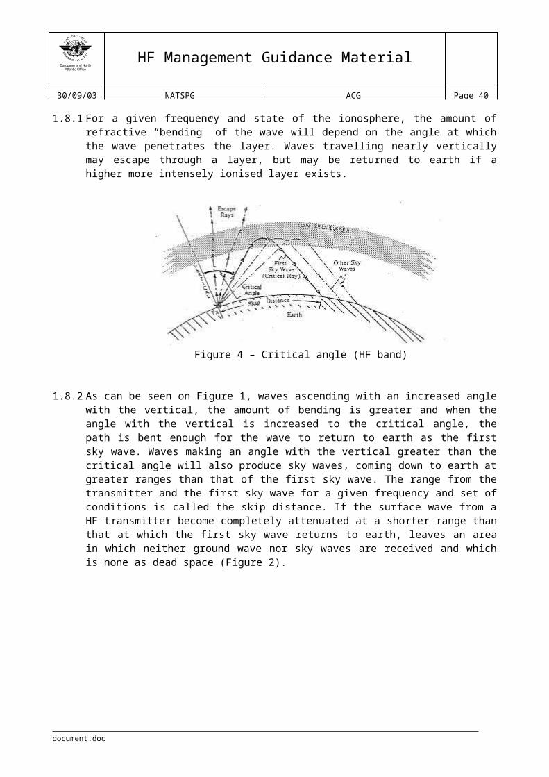
1.8.1 For a given frequency and state of the ionosphere, the amount of refractive “bending” of the wave will depend on the angle at which the wave penetrates the layer. Waves travelling nearly vertically may escape through a layer, but may be returned to earth if a higher more intensely ionised layer exists.
Figure 4 – Critical angle (HF band)
1.8.2 As can be seen on Figure 1, waves ascending with an increased angle with the vertical, the amount of bending is greater and when the angle with the vertical is increased to the critical angle, the path is bent enough for the wave to return to earth as the first sky wave. Waves making an angle with the vertical greater than the critical angle will also produce sky waves, coming down to earth at greater ranges than that of the first sky wave. The range from the transmitter and the first sky wave for a given frequency and set of conditions is called the skip distance. If the surface wave from a HF transmitter become completely attenuated at a shorter range than that at which the first sky wave returns to earth, leaves an area in which neither ground wave nor sky waves are received and which is none as dead space (Figure 2).
Figure 5 – Dead space (HF band)
document.doc

HF Management Guidance Material
30/09/03 NATSPG ACG Page 28
1.8.3 Critical angle depends largely on the frequency, the higher the frequency the greater the critical angle, therefore, if skip distance is to be reduced, a lower frequency has to be used. This is most significant when choosing the optimum frequencies for HF communications and ensuring that the skip distance is less than the range of the distant receiver.
1.8.4 For good long-range HF R/T reception a frequency must be chosen which will not suffer too much attenuation. If a relatively high frequency is used, for example 29 MHz, most of the energy will pass through the E layer and be reflected from the more intensely ionised F layer. The higher the frequency, the greater degree of ionisation is required to give reflection. As frequency is reduced and attenuation of the E layer reflections increases, a limit is reached called the “Lowest Usable Frequency (LUF)”, and bellow this frequency the attenuation is too great for the signal to be usable.
1.8.5 Thus for least attenuation, and so the highest received signal strength for a given transmitter power, a frequency is chosen which is as high as possible without exceeding the MUF (Maximum Usable Frequency) for the path between the transmitter and distant receiver. The MUF is that frequency, for the prevailing conditions, which produces a skip zone extending just short of the distant receiver. Any higher frequency would give a higher critical angle and a greater skip distance exceeding beyond the receiver, which would then loose that sky wave contact with the transmitter.
1.8.6 MUF at night is much less than by day, because the intensity of ionisation in the layer is less so than lower frequencies have to be used to produce the same amount of refractive bending and give the same critical angle and skip distance as by day. However, the signal attenuation in the ionosphere in the ionosphere is also much less at night so the lower frequency needed is still usable. Hence the night frequency for a given path is about half of the day frequency, and shorter distances can be worked at night than by day while still using a single reflection from the F layer.
1.8.7 The MUF not only varies with path length and between day and night, but also with season, meteor trails, sunspot state, and sudden ionospheric disturbances produced by eruptions on the sun. Because of the variations of MUF, HF transmitting stations have to use frequencies varying widely between about 2 and 20 MHz.
1.9 The theoretical range for HF frequencies varies, depending on the propagation path used, ground or sky waves. Ground waves usually can reach up to 100 nm and sky waves longer distances, however, sky waves will not be received within the skip distance (probably several hundred miles from the transmitter). The theoretical maximum range obtained by means of a single reflection from the E layer is about 1 300 nm, and from the F layer about 2 500 nm. This theoretical maximum range is achieved with the transmitted signal leaving the earth’s surface tangentially. Ranges of 8 000 nm or more may be achieved by means of multiple reflections, mainly from the F layer, being the signal alternately refracted down from the layer and reflected up again from the earth’s surface until it becomes too weak to use.
document.doc
HF Management Guidance Material
30/09/03 NATSPG ACG Page 29
Appendix B-1 - BODO Radio Station Information
Station Name: Bodo Radio Country: Norway State: NordlandCity: Bodo Geographic Location: 67°16´09N014°21´55E
AFTN Address: ENBOYSYX Aircraft in Flight Address: ENBOZZZXSATCOM SHORT CODE Nr. : 425702
FacilitiesTransmitter site(s) Receiver site(s)Location and equipment: Location and equipment:Bodo 67°16´N 014°21´E1 Marconi H1141 (10 kW)1 Harris RF-765A (5 kW)
Andoya 69°10´N 015°50´E1 Harris RF-765A (5 kW) Berlevaag 70°50´N 029°E(1 Marconi H1141 mk2 (10 kW) )(expected operational late 2003)
Bodo 67°16´N 014°21´E6 Rhode & Schwarz EK895/896
Andoya 69°10´N 015°50´E4 Rhode & Schwarz EK896
(North Cape 71N 025.30E) (X Rhode & Schwarz EK896)(expected operational late 2003)
Class of Emission: USB/AM SELCAL: 2 Baumberger selcal-coder
Frequencies
Family Frequency bands 3 MHz 3.5 MHz 4.7 MHz 5.6 MHz 6.6 MHz 9 MHz 11.3 MHz 13.3 MHz 18 MHz
D 2971 4675 8891 112791C 2983 4666 6544 8840
SAR 3023 5680
Station Manager * SupervisorName: Ole Petter Nordnes Name: Leiv Torbjorn Herseth Post Address: AVINORN-8041 BODO
Post Address: AVINORN-8041 BODO
Phone: + 47 75543050 Phone: + 47 75543057Fax: + 47 75543010 Fax: + 47 75542943Email: [email protected] Email: [email protected]/SITA Address: ENBOYFYX AFTN/SITA Address: ENBOYFYX
Remarks: Bodo HF radio is collocated and is a department within Bodo ATCC. * Chief Controller Bodo ATCC
document.doc

HF Management Guidance Material
30/09/03 NATSPG ACG Page 30
Appendix B-2 - GANDER Radio Station Information
Station Name: Gander RadioCountry: Canada State: NewfoundlandCity: Gander Geog. Location: 48°57´58.5N054°35´50.7W
AFTN Address: CYQXYSYX Aircraft in Flight Address: CYQXZZZXSATCOM SHORT CODE Nr. : 431613
FacilitiesTransmitter site Receiver siteLocation: 48°58´95N054°40´28W Location: 48°57´54N054°33´42W
Equipment Equipment22 Harris RF727 (5 KW)4 Aerocom 1330 (5 KW)18 tuned ¼ wave dipole main antennasBroadband backup antennas
22 Nardeux NC100 receiversSingle vertical antenna utilizing a multi-coupler4 Main vertical pole VOLMET antennas4 Backup vertical pole VOLMET antennas
Class of Emission: USB/AM SELCAL: 10 Motorola Units
Frequencies
Family Frequency bands 3 MHz 3.5 MHz 4.7 MHz 5.6 MHz 6.6 MHz 9 MHz 11.3 MHz 13.3 MHz 18 MHz
A 3016 5598 8906 13306B 2899 5616 8864 13291C 2872 5649 8879 11336 13306D 2971 4675 8891F 3476 6622 8831 13291
VOLMET 3485 6604 10051 13270
Station Manager On Duty SupervisorName: Bruce Hoddinott Post Address:
NAV CANADAP.O Box 328Gander, NL Canada A1V 2R3
Post Address:NAV CANADAP.O Box 328Gander, NL Canada, A1V 2R3Phone: + 1 709 651 5213 Phone: + 1 709 651 5212Fax: + 1 709 651 5235 Fax:Email: [email protected] Email:AFTN/SITA Address: CYQXYSYX AFTN/SITA Address: CYQXYSYX
Remarks: Gander Radio is collocated within Gander OACC.
document.doc
HF Management Guidance Material
30/09/03 NATSPG ACG Page 31
Appendix B-3 - ICELAND Radio Station Information
Station Name: Iceland RadioCountry: Iceland State: City: Reykjavik Geographic Location: 64°08´53N 021°47´39W
AFTN Address: BICCYSYX Aircraft in Flight Address: BICCZZZXSATCOM SHORT CODE Nr. : 425105
FacilitiesTransmitter site Receiver siteLocation: 64°05´06N 021°50´43W Location: 64°34´32N 022°08´46W
Equipment Equipment2 Aerocom 1330 (5KW)2 JRC JRS 753 AM (5KW)5 Marconi H1141 (10KW)1 Andrews 3001 Omni-directional antenna 1 Andrews 747 log periodic antenna 2 TCI log periodic antennas 532Dipole antennas
4 JRC NRD 95 receivers15 JRC NRD 253 receivers 1 JRC NRD 302A receivers 5 TCI log periodic antennas 548, also access to Granger 2001 elliptically polarised antenna and Granger 3001 omni-directional antenna selectable through coax switches/multicouplers3 JRC NRD 95 receivers as backup1 JRC NRD 302A receivers as backup1 T antennas as backup, also access toanother T antenna.
Class of Emission: SSB/AM (J3E/H3E) SELCAL: 8 Motorola N1304A
Frequencies
Family Frequency bands 3 MHz 3.5 MHz 4.7 MHz 5.6 MHz 6.6 MHz 9 MHz 11.3 MHz 13.3 MHz 18 MHz
B 2899 5616 8864 13291C 2872 5649 8879 13306 17946D 2971 4675 8891 11279
Station Manager On Duty SupervisorName: Reynir Eggertsson Post Address: Iceland Telecom Ltd.
Smárarimi 1IS-112 ReykjavíkIceland
Post Address: Iceland Telecom Ltd.Smárarimi 1IS-112 ReykjavíkIcelandPhone: + 354 550 6539 Phone: + 354 553 3032Fax: + 354 567 5230 Fax: + 354 562 9043Email: [email protected] Email: [email protected] AFTN/SITA Address: BICCYFYX AFTN/SITA Address: BICCYFYX
document.doc
HF Management Guidance Material
30/09/03 NATSPG ACG Page 32
Remarks:
document.doc

HF Management Guidance Material
30/09/03 NATSPG ACG Page 33
Appendix B-4 - NEW YORK Radio Station Information
Station Name: New York RadioCountry: United States of America State: New YorkCity: Bohemia, Long Island Geographic Location: 40.46.79N0730572WAFTN Address: KNYCXAAG Aircraft in Flight Address: KNYCZZZXSATCOM SHORT CODE Nr. : 436623
FacilitiesTransmitter site Receiver siteLocation: Riverhead, (40.52.52N072.38.52W) Location: SouthHampton (40.55.15N072.23.41W)
Equipment Equipment7 Cubic CTX-5000 (5 KW)2 HFDL transmitters3 Grainger log periodic antennas (2.8-32 MHz)2 Grainger log periodic antennas (5.4-32 MHz)2 Grainger log periodic antennas (6.5-32 MHz)1 TCI log periodic antenna2 Tuned dipole antennas (HFDL)1 TCI omni-log periodic antenna (4-28 MHz)1 Dipole for CAR-B 3455 MHz1 Cubic Transmitter (1 KW) Standby
36 Cubic LCD2000 receivers6 Aerocom 2215 receivers for LDOCF2 HFDL receivers3 Aerocom 2217 used only by maintenance1 Log periodic north-east antenna1 Log periodic south antenna1 Omni directional antenna(Each antenna has a multi-couple for distribution of signals to the receivers)
Class of Emission: 1K40H2B/2K80J3E SELCAL: 14 Baker Units
Frequencies
Family Frequency bands 3 MHz 3.5 MHz 5.6 MHz 6.6 MHz 9 MHz 11.3 MHz 13.3 MHz 18 MHz 22 MHz
A 3016 5598 8906 13306 17946 21964E 2962 6628 8825 11309 13354 17952
CAR A 2887 5550 6577 8846 11396 13297CAR B 3455 5520 6586 8918 11330 17907
VOLMET 3485 6604 10051 13270LDOCF 3494 6640 8933 11342 13330 17925
Station Manager On Duty SupervisorName: Peter Henschke Post Address:
New York Communications Center613 Johnson AveBohemia, Long Island, NY 11716-2696
Post Address:New York Communications Center613 Johnson AveBohemia, Long Island, NY 11716-2696Phone: + 1 631 244 2480 Phone: + 1 631 244 2480Fax: + 1 631 563 2412 Fax: + 1 631 563 2412Email: [email protected] Email: [email protected] AFTN/SITA Address: KNYCXGXA AFTN/SITA Address: KNYCXGXA
Remarks: The communications control point is located at Bohemia, New York, and the transmitters are located at Riverhead, New York, on the east end of Long Island. The receivers are located at South Hampton, New York, also located on the east end of Long Island. New York radio is located less than 1 mile from New York ACC. Backup receiver located at New York radio; backup transmitters located less than 2 miles away at Islip Long Island Airport.
document.doc

HF Management Guidance Material
30/09/03 NATSPG ACG Page 34
Appendix B-5 - SANTA MARIA Radio Station Information
Station Name: Santa Maria RadioCountry: Portugal State: Santa Maria - AzoresCity: Vila do Porto Geographic Location: 36°58´21N025°09´54W
AFTN Address: LPAZYSYX Aircraft in Flight Address: LPAZZZZXSATCOM SHORT CODE Nr. : 426305
FacilitiesTransmitter site Receiver siteLocation: Cabrestantes (36°59´44N025°10´14W) Location: Faneca (36°59´44N025°07´48W)
Equipment Equipment10 INTECH 5000C (5KW)3 Harris RF765-A (5 KW) backup TX7 Andrews 1765 omni antennas1 Andrews 2726 vertically log periodic antenna (west)1 Andrews 747FCD horizontally log periodic antenna (north)1 Delta antennas switch matrix
13 Harris R2368-A receivers1 Hermes 24 loop array that allows 3 directional antennas (north, southeast and southwest) and 1 omni antenna (medium-long range)1 Harris RF1976 omni antenna (short-medium range)1 PG Electronics antennas switch matrix/multi coupler1 Harris RF1956 omni antenna utilizing a multi coupler as backup
Class of Emission: A3J/AM SELCAL: 5 Motorola encoder 1304A
Frequencies
Family Frequency bands 3 MHz 3.5 MHz 4.7 MHz 5.6 MHz 6.6 MHz 9 MHz 11.3 MHz 13.3 MHz 18 MHz
A 3016 5598 8906 13306 17946E 2962 6628 8825 11309 13354
Station Manager On Duty SupervisorName: Jose Cabral Post Address: NAV PORTUGAL
APARTADO 47AEROPORTO SANTA MARIA9580-909 VILA DO PORTO
Post Address: NAV PORTUGALAPARTADO 47AEROPORTO SANTA MARIA9580-909 VILA DO PORTOPhone: + 351 296 820 510 Phone: + 351 296 820 423Fax: + 351 296 820 552 Fax: + 351 296 820 450Email: [email protected] Email: [email protected] AFTN/SITA Address: LPAZYFYA AFTN/SITA Address: LPAZYSYX
Remarks: Santa Maria radio is collocated and is a department within Santa Maria OACCBackup receiver site is also located in the vicinity of Santa Maria OACC
document.doc

HF Management Guidance Material
30/09/03 NATSPG ACG Page 35
Appendix B-6 - SHANWICK Radio Station Information
Station Name: Shanwick RadioCountry: Republic of Ireland State: County ClareCity: Shannon Geographic Location: 52°47´N 008°55´W
AFTN Address: EIAAYSYX Aircraft in Flight Address: EIAAZZZXSATCOM SHORT CODE Nr. : 425002
FacilitiesTransmitter site Receiver siteLocation: Urlanmore (52°45´N 008°56´W) Location: Ballygirreen (52°47´N 008°55´W)
Equipment Equipment14 SPT/Redifon 5KW 6 channel TX2 Aerocomm 1330 5KW 6 channel TX6 SPT/Redifon 5KW 6 channel TX Volmet6 Omni-directional antennas5 Vertical Log Periodic (directionally diverse)2 Broadband Dipoles 2-13MHz2 Cubic IKW 249 channel Data-link TX (In association with ARINC)
17 Philips Fixed channel Rx7 Dansk Tuneable Rx3 Horizontal Log Periodic Antennas1 "T" Antenna1 Rhombic Antenna5 Antenna Multicouplers
Class of Emission: J3E/H3E SELCAL: Baumberger (12)
Frequencies
Family Frequency bands 3 MHz 3.5 MHz 4.7 MHz 5.6 MHz 6.6 MHz 9 MHz 11.3 MHz 13.3 MHz 18 MHz
A 3016 5598 8906 13306B 2899 5616 8864 13291C 2872 5649 8879 11336 13306D 2971 4675 8891 13291F 3476 6622 8831 13291
SAR 2182 3023 5680VOLMET 3413 5505 8957 13264
Station Manager On Duty SupervisorName: Harry O'Loughlin Post Address: Irish Aviation Authority,
Shannon Aeradio, BallygirreenNewmarket on Fergus, Co. ClareIRELAND.
Post Address: Irish Aviation AuthorityShannon Aeradio, Ballygirreen Newmarket on Fergus, Co. ClareIRELAND.Phone: + 353 61 703803 Phone: + 353 61 368241Fax: + 353 61 703853 Fax: + 353 61 472528Email: [email protected] Email:AFTN/SITA Address: EIAAYTYX AFTN/SITA Address: EIAAYFYX
document.doc

HF Management Guidance Material
30/09/03 NATSPG ACG Page 36
Remarks: By international agreement Shanwick Radio provides communications services for the Shanwick OCA. The associated OACC is located at Prestwick, Scotland, U.K.
document.doc

HF Management Guidance Material
30/09/03 NATSPG ACG Page 37
Appendix C-1 - BODO Radio Station Frequencies Hours of Service
document.doc Version 1.0 - 2003
NAT Family Frequency 00 01 02 03 04 05 06 07 08 09 10 11 12 13 14 15 16 17 18 19 20 21 22 23
NAT Family D
2971 kHz
4675 kHz
8891 kHz
11279 kHz
Hours of OperationBODO Radio Station

HF Management Guidance Material
30/09/03 NATSPG ACG Page 38
Appendix C-2 - GANDER Radio Station Frequencies Hours of Service
document.doc Version 1.0 - 2003
NAT Family Frequency 00 01 02 03 04 05 06 07 08 09 10 11 12 13 14 15 16 17 18 19 20 21 22 23
NAT Family A
3016 kHz Ending 0830Z Starting 2030Z
5598 kHz
8906 kHz Starting 0830Z Ending 2230Z
13306 kHz Starting 1230Z Ending 1830Z
17946 kHz
NAT Family B
2899 kHz Ending 0830Z Starting 2030Z
5616 kHz
8864 kHz Starting 0830Z Ending 2230Z
13291 kHz
NAT Family C
2872 kHz Ending 0830Z Starting 2030Z
5649 kHz
8879 kHz Starting 0830Z Ending 2230Z
11336 kHz Starting 1030Z Ending 1830Z
NAT Family D
2971 kHz Ending 0830Z Starting 2030Z
4675 kHz
8891 kHz Starting 0830Z Ending 2230Z
11279 kHz13291 kHzNAT Family F
3476 kHz Ending 0830Z Starting 2030Z13291 kHz6622 kHz13291 kHz8831 kHz Starting 0830Z Ending 2230Z13291 kHzHours of Operation as required
Hours of OperationGander Radio Station

HF Management Guidance Material
30/09/03 NATSPG ACG Page 39
Appendix C-3 - ICELAND Radio Station Frequencies Hours of Service
document.doc Version 1.0 - 2003
NAT Family Frequency 00 01 02 03 04 05 06 07 08 09 10 11 12 13 14 15 16 17 18 19 20 21 22 23
NAT Family B
2899 kHz
5616 kHz
8864 kHz
13291 kHz
17946 kHz
NAT Family C
2872 kHz
5649 kHz
8879 kHz
13306 kHz
NAT Family D
2971 kHz
4675 kHz
8891 kHz
11279 kHz
13291 kHz
Hours of OperationIceland Radio Station
HF Management Guidance Material
30/09/03 NATSPG ACG Page 40
Appendix C-4 - NEW YORK Radio Station Frequencies Hours of Service
document.doc Version 1.0 - 2003
NAT Family Frequency 00 01 02 03 04 05 06 07 08 09 10 11 12 13 14 15 16 17 18 19 20 21 22 23
NAT Family A
3016 kHz
5598 kHz
8906 kHz
13306 kHz
17946 kHz
NAT Family E
2962 kHz
6628 kHz
8825 kHz
11309 kHz
13354 kHz
13291 kHz
Hours of OperationNew York Radio Station

HF Management Guidance Material
30/09/03 NATSPG ACG Page 41
Appendix C-5 - SANTA MARIA Radio Station Frequencies Hours of Service
document.doc Version 1.0 - 2003

HF Management Guidance Material
30/09/03 NATSPG ACG Page 42
NAT Family Frequency 00 01 02 03 04 05 06 07 08 09 10 11 12 13 14 15 16 17 18 19 20 21 22 23
NAT Family A
3016 kHz
5598 kHz
8906 kHz
13306 kHz
17946 kHz
NAT Family E
2962 kHz
6628 kHz
8825 kHz
11309 kHz
13354 kHz
Note 1: Whenever required Santa Maria Radio Station will use the available frequencies outside the defined hours of operation.
Note 2: On duty Supervisor will previously coordinate the new hours of frequency whenever required.13291 kHz
Hours of OperationSanta Maria Radio Station
document.doc Version 1.0 - 2003
HF Management Guidance Material
30/09/03 NATSPG ACG Page 43
Appendix C-6 - SHANWICK Radio Station Frequencies Hours of Service
document.doc Version 1.0 - 2003
NAT Family Frequency 00 01 02 03 04 05 06 07 08 09 10 11 12 13 14 15 16 17 18 19 20 21 22 23
NAT Family A
3016 kHz
5598 kHz
8906 kHz
13306 kHz
17946 kHz
NAT Family B
2899 kHz
5616 kHz
8864 kHz
13291 kHz
NAT Family C
2872 kHz
5649 kHz
8879 kHz
11336 kHz
NAT Family D
2971 kHz
4675 kHz
8891 kHz
11279 kHz13291 kHzNAT Family F
3476 kHz13291 kHz6622 kHz13291 kHz8831 kHz13291 kHzHours of Operation only as required
Hours of OperationShanwick Radio Station

HF Management Guidance Material
30/09/03 NATSPG ACG Page 44
---- END of Document ---
document.doc Version 1.0 - 2003