heteroazeotropic batch distillatioin feasibility and operation
TRANSCRIPT

Efstathios Skouras-Iliopoulos
Doctoral thesis for the degree of doktor ingeniør
Trondheim, May 2004
Heteroazeotropic BatchDistillation:Feasibility and Operation
Norwegian University of Science and TechnologyFaculty of Chemistry and BiologyDepartment of Chemical Engineering

Heteroazeotropic Batch Distillation Feasibility and Operation
by
Efstathios Skouras-Iliopoulos
A Thesis Submitted for the Degree of Dr. Ing.
Norwegian University of Science and Technology
Department of Chemical Engineering
ISBN 82-471-6301-2 (electronic) ISBN 82-471-6302-0 (printed)
Dr. ing. thesis 2004:47


i
Abstract
Separation of azeotropic mixtures is of great industrial importance and distillation is the dominating unit operation for such separations. However, the presence of azeotropes and non-idealities in the phase behaviour of such mixtures complicates the separation. In the pharmaceutical and fine/specialty chemical industry, the small-scale production and the requirement for flexibility indicates batch distillation as the best suited process. Among, various techniques to enhance distillation, heterogeneous azeotropic (heteroazeotropic) distillation is a very powerful and widely used one. Thus, there is a need for deeper understanding of the complex behaviour of the separation of heteroazeotropic mixtures in batch distillation columns. This thesis is concerned with feasibility and operation aspects of heteroazeotropic distillation in different batch column configurations. Both conventional batch columns (rectifiers) and novel configurations (multivessel columns), with and without vapour bypass, are considered. The focus is on closed operations, without product removal. Batch time requirements for operation in all columns are provided for both zeotropic and heteroazeotropic mixtures. The advantages and drawbacks of each configuration are discussed and compared based on dynamic simulations. The configuration of the vapour stream in the middle vessel has an important effect on the time requirements of the process. Later on, a detailed analysis of the process is provided and previous published work concerning different operation modes and separation strategies is put under the right perspective. Simple control schemes are proposed for the practical operation of the columns and the realisation of the desired steady state results. The thesis ends with a detailed feasibility study of the process. The possibilities and limitations raised by different operational modes and separation strategies are illustrated. Simple feasibility conditions and entrainer selection rules are formulated that allow someone to investigate feasibility of the process in a systematic and comprehensive manner.


iii
Acknowledgements
It is not easy to write these final words. There are so many things that I would like to write about and so many people that I would like to mention. People I met in Norway and we shared moments and thoughts and since then we keep on doing so. Thanks to Kjetil, Aletta, Djordje, Jean-Christophe, Matthieu, Michalis, Nikos and the international community at Moholt and Steinan for all the nice times we had together the first years. I am grateful to my supervisor Sigurd Skogestad for giving me the opportunity to do my PhD in Norway. I enjoyed a lot being in his research group, where I had the freedom to participate in conferences and meet people from the academia all around the world. Thank him also for his continuous engagement and contribution to this work. I am also grateful to my co-supervisor Valeri Kiva for involving himself in this project during the last year. His systematic way of working and his deep knowledge on distillation certainly improved the quality of this thesis. But most of all, I want to thank him for inspiring me. Thanks to all my former and present colleagues for creating a good working and social environment and for helping me with Matlab. I would especially like to thank Hilde Engelien for being always helpful and kind, from the very first day I came in Norway, and for sharing all the ups and downs during these years.
I want also to thank my family and my friends in Greece for supporting me in everything I do in life. It is important to know that they always think of me. A special thank to my friend Themis in Athens for the numerous discussions that helped me to stay dedicated to my target. Finally, I want to thank you Vibeke. You were always the most important person for me in Norway, first as a friend and now as my partner in life and mother of my kid. Thanks for all your love, support and understanding. Now at the end of my education, I would like to express my deepest gratitude to the person that contributed most in it. To Grigorios Rouskas, my old teacher in the 4th and 5th class in the 9th Primary School in Lamia, I dedicate this thesis.


v
TABLE OF CONTENTS
Abstract .……………………………………………………. i Acknowledgements ……………...………………................. iii Table of contents .…………………………………………... v-vii CHAPTER 1 Introduction .……………………………………………….. 1-8 1 Motivation and industrial relevance ……..……………… 1 2 Thesis overview ..………………………………………... 4 3 References ..……………………………………………... 7 CHAPTER 2 Time requirements in closed batch distillation
arrangements ………………………………………………. 9-31
Abstract ..………………………………………………... 9 1 Introduction…...…………………………………………. 10 2 Simulations …..………………………………………….. 13 2.1 The model …………………………………………. 13 2.2 Simulation details …………………………………. 13 3 Results …..………………………………………………. 16 3.1 Base case-equimolar feed …………………………. 16 3.2 Effect of the feed composition ...………………….. 24 4 Conclusions ..……………………………………………. 27 5 Notation ..………………………………………………... 28 Appendix ..………………………………………………. 29 6 References ..……………………………………………... 30 CHAPTER 3 Separation of ternary heteroazeotropic mixtures in a
closed multivessel batch distillation-decanter hybrid .…... 33-60 Abstract ………..………………………………………... 33 1 Introduction ……..………………………………………. 34 1.1 Previous work on the multivessel column ………… 34 1.2 Previous work on azeotropic mixtures ……………. 36 1.3 This study …………………………………………. 37 2 Qualitative description ………………………..………… 40 2.1 Serafimov’s topological class 1.0-2 ……...……….. 40 2.2 Serafimov’s topological class 1.0-1a ...…………… 43 2.3 Serafimov’s topological class 2.0-2b ...…………… 45 3 Simulation results ..……………………………………… 47 3.1 Serafimov’s topological class 1.0-2 ...…………….. 47 3.2 Serafimov’s topological class 1.0-1a ...…………… 50 3.3 Serafimov’s topological class 2.0-2b …………...… 50 4 Conclusions ..……………………………………………. 53 5 Nomenclature ..………………………………………….. 54 Appendix ..………………………………………………. 55 6 References …..…………………………………………... 58

vi
CHAPTER 4 Time requirements for heteroazeotropic distillation in batch columns ………………………………………………
61-92
Abstract ..………………………………………………... 61 1 Introduction …..…………………………………………. 62 2 Simulations ..…………………………………………….. 67 2.1 The model …………………………………………. 67 2.2 Simulation details …………………………………. 67 3 Results ………………………..…………………………. 70 3.1 Serafimov’s topological class 1.0-2 ………………. 70 3.2 Serafimov’s topological class 1.0-1a ……………... 77 3.3 Serafimov’s topological class 2.0-2b ……..………. 83 4 Conclusions ..……………………………………………. 86 5 Notation …..……………………………………………... 87 Appendix …..……………………………………………. 88 6 References ..……………………………………………... 90 CHAPTER 5 Heteroazeotropic batch distillation:
Process analysis and simulation results .………………….. 93-128 Abstract ……..…………………………………………... 93 1 Introduction ..……………………………………………. 94 2 Rectifier column ..……………………………………….. 98 2.1 Process description ...……………………………... 98 2.2 Separation strategies ………………………………. 100 2.3 Implementation: Previous work ………..………… 103 2.4 Implementation: New T-control strategy …………. 104 3 Multivessel column …..…………………………………. 106 3.1 Process description ………………………………... 106 3.2 Control scheme ……………………………………. 106 4 Simulation results …………………………..…………… 108 4.1 Serafimov’s topological class 2.0-2b ...…………… 108 4.2 Serafimov’s topological class 3.1-2 ...…………….. 115 5 Conclusions ..……………………………………………. 121 6 Notation ..………………………………………………... 122 Appendix ..………………………………………………. 123 7 References ..……………………………………………... 126 CHAPTER 6 Heteroazeotropic batch distillation:
Feasible separations and entrainer selection rules ..……... 129-163 Abstract ………………………………………………..... 129 1 Introduction …..…………………………………………. 130 2 Feasibility analysis for the working example ..………….. 134 2.1 Feasibility for Modes I and II ……………………... 134 2.2 Feasibility in the rectifier column ………………… 136 2.3 Feasibility in the multivessel column ……………... 140 3 General feasibility conditions …..……………………….. 141 4 Feasibility for various cases …..………………………… 143 4.1 Case a: Original mixture (AB) is close-boiling …… 144

vii
4.2 Case b: Original mixture (AB) is minimum-boiling homoazeotropic ……………………………………
149
4.3 Case c: Original mixture (AB) is maximum-boiling homoazeotropic ……………………………………
152
4.4 Pure original component from the entrainer-lean phase ……………………………………………….
155
5 Entrainer selection rules …..…………………………….. 157 6 Conclusions …..…………………………………………. 159 7 Notation …..……………………………………………... 160 Appendix ..………………………………………………. 161 8 References ..……………………………………………... 162 CHAPTER 7 Concluding remarks and suggestions for future work .…. 165-167 1 Concluding remarks ……..……………………………… 165 2 Suggestions for future work ..…………………………… 166 APPENDIX Description of the model ..…………………………………. 169-173 1 Model assumptions ...……………………………………. 169 2 Model equations ……..….………………………………. 169 3 Notation ………………...……………………………...... 172 4 References …………………………………………......... 173


1
Chapter 1
INTRODUCTION
1. Motivation and industrial relevance Recovery and recycle of organic solvents is a common task in the organic chemical industry dictated by the need to meet strict environmental regulations and the potential economic benefits from a more efficient use of the solvents used in the plant. Among many unit operations, distillation is the most common one because of its ability to produce products of high purity. However, the solvent streams to be processed are rarely exhibiting ideal phase equilibrium behaviour. Non-ideal behaviour and azeotropy complicates the synthesis and the conceptual design of such distillation-based processes. In the pharmaceutical and fine/specialty chemical industry, small-scale production of high-added value products and frequent change of the separation task favours the use of flexible batch equipment (Hilmen, 2000), Thus, batch distillation columns are the “heart” of the solvent recovery and recycle units in such industries and investigating feasibility and operation issues for batch distillation of azeotropic mixtures is an important issue both for the academia and the industry. The most common batch distillation column in the industry is the so-called batch rectifier and therefore rectifier configurations are investigated in this thesis. In the academia much attention has been given lately to a special batch configuration called multivessel column or middle vessel column (Robinson and Gilliland, 1950). The novel column has both a rectifying and a stripping section and it is possible to obtain a light and a heavy fraction simultaneously from the top and the bottom of the column, while an intermediate fraction may also be recovered in the middle vessel (Hasebe et al., 1992; Skogestad et al., 1997). Such multivessel configurations are also included in this study. The multivessel column can be practically realised as a set of already existing batch rectifiers connected sequentially (Hasebe et al., 1995). In this case we talk about the multivessel column with vapour bypass streams in the intermediate vessels. In the case of a new multivessel column, built from scratch, design modifications like for example eliminating the vapour bypass or having a liquid bypass can be advantageous depending on the separation task (Warter and Stichlmair, 1999 and Low and Sorensen, 2002). Modified multivessel configurations with no vapour bypass are also investigated in this thesis. Distillation-based separation processes are based on the differences on the vapour and liquid phase compositions of the mixture arising from successive

2
partial vaporisation and condensation steps. However, in case of a close-boiling (low relative volatility) mixture these differences in the compositions of the vapour and the liquid phase become small. The process requires then many vaporisation/condensations steps and often becomes uneconomical. The situation is even worse for azeotropic mixtures because the vapour and liquid phases have identical compositions and the separation stops. In order to facilitate separation and enhance distillation, advanced techniques are required. Several such techniques have been proposed and in the most common books in the area (Perry et al., 1997; Stichlmair and Fair, 1998 and Doherty and Malone, 2001) the methods are classified based on different criteria. Suppose we want to separate an initial binary azeotropic mixture. The most common enhanced distillation techniques are: i) Pressure-swing distillation, ii) Homogeneous azeotropic (homoazeotropic) distillation, iii) Heterogeneous azeotropic (heteroazeotropic) distillation, iv) Extractive distillation and v) Extractive heterogeneous (heteroextractive) azeotropic distillation. i) Among these five methods, pressure-swing distillation is the only one that does not require the addition of a third component, called entrainer, to the initial mixture. The principle is to overcome the azeotropic composition by changing the pressure of the system. This method is applicable in both continuous and batch columns but it is applicable only for mixtures sensitive to pressure e.g. the system tetrahydrofuran/water presented by Stichlmair and Fair (1998).
ii) Homoazeotropic distillation requires the addition of an entrainer miscible with the original components that results in a ternary phase equilibrium diagram that is promising for separation (Hilmen, 2000). Stichlmair and Fair (1998) classifies such processes in two main categories: a) processes in one distillation field without boundary crossing and b) processes in two distillation fields which require a boundary crossing technique to be applied. Such processes have been described for both continuous columns (Doherty and Caldarola, 1986 and Stichlmair and Herguijuela, 1992) and batch columns (Bernot et al., 1991 and Duessel and Stichlmair, 1995). In continuous columns, the process is carried in a single-feed column, while in batch columns the entrainer is added batchwise to the original mixture. Unfortunately, the applicability of the process is limited. In case (a) it is difficult to find entrainers that do not introduce boundaries in the ternary mixture and in case (b) it is practically difficult to implement boundary crossing techniques. However, few industrial applications of boundary crossing techniques do exist, e.g. the cases of hydrochloric acid-water and nitric acid-water separation by using sulphuric acid as entrainer (Perry et al., 1997 and Stichlmair and Fair, 1998).

Chapter 1. Introduction 3
iii) Heterogeneous azeotropic (heteroazeotropic) distillation requires the addition of an entrainer which is partially miscible and forms heterogeneous azeotrope with one (and preferably with only one) of the original components. The added entrainer should result to a ternary phase equilibrium diagram that is promising for separation. This powerful method, which combines several physical phenomena (presence of azeotropes and liquid-liquid immiscibilities) in order to enhance difficult or otherwise infeasible distillation separations, is widely used in the industry. Industrial examples are presented in Perry et al. (1997), Stichlmair and Fair (1998) and also Doherty and Malone (2001). It is worthy to mention that the first patents for this method, for the production of absolute ethanol from a water-ethanol mixture by using benzene as entrainer, were received in 1903 by Young in Germany for batch columns and in 1915 by Kubierschky for continuous columns (Doherty and Malone, 2001). As in homoazeotropic distillation, the separation is carried in a single-feed continuous column or in batch columns, the entrainer is added batchwise to the original mixture. A decanter is also required and combined with the column for performing the liquid-liquid split. iv) Extractive distillation is another powerful technique that requires an entrainer that interacts selectively with the original components (mostly in the liquid phase) and alters their relative volatility, thus enhancing the original separation. Stichlmair and Fair (1998) consider this method as a hybrid one where distillation is combined with absorption, while Doherty and Malone (2001) consider it as a special case of homoazeotropic distillation. In any case, extractive distillation is the most widely used enhanced distillation method in the chemical process industry (Perry et al. 1997) and is consequently well studied in the literature. The process in its classical version is carried in a double-feed continuous column with a heavy entrainer added continuously somewhere in the top of the column. Extractive distillation is widely used in the petrochemical industry where continuous distillation is the rule. However, the extension of the method to batch rectifiers and multivessel configurations (Safrit and Westerberg, 1997; Warter and Stichlmair, 1999; Hilmen, 2000 and Low and Sorensen, 2002) has also been discussed but no industrial application has been reported yet. v) Heteroextractive distillation is, as the name indicates, a hybrid process where heteroazeotropic and extractive distillation are combined in a single process. The process requires the addition of an entrainer that forms a heteroazeotrope with only one (preferably) of the original components and at the same time interacts with the original components and changes its relative volatility. Since the added entrainer is double-effective, the process becomes very attractive. However, it is a rather “new” process and thus, not covered by most of the books in the area. Nevertheless, it has be studied in few papers in the Russian literature for continuous columns (examples given by Hilmen, 2000) and lately in the Western

4
literature for both continuous (Szanyi et al., 2004) and batch columns (Koehler et al., 1995; Modla et al., 2003; Rodriguez et al., 2003). Overall we can say that among the aforementioned five techniques, heteroazeotropic distillation (iii) and extractive distillation (iv) are the most realistic alternatives for the separation of azeotropic mixtures. Both processes can be used for the separation of components of different chemical nature but extractive distillation is less sensitive to such differences. In addition, most organic substances are totally miscible with each other and thus, heteroazeotropic distillation is mainly applied for the dehydration of organic substances with some organic entrainer or for separation of organic substances with water as an entrainer. Extractive distillation can be used much more widely and this is one of the reasons of the great industrial applicability of the process. However, a big advantage of heteroazeotropic distillation is the easier realisation of the process for small-scale industries in batch columns, while, as mentioned before, batch extractive distillation has serious practical drawbacks. 2. Thesis overview This thesis deals with heteroazeotropic distillation in different batch column configurations. The great applicability of the process in the industry simply indicates the practical importance and the industrial relevance of this dissertation. Feasibility and operation aspects are discussed in both rectifier and multivessel configurations. The complexity imposed in the phase equilibrium diagrams by the presence of azeotropes makes feasibility the first issue to be addressed in azeotropic distillation. Thus, it is our objective to develop simple methods in order to distinguish between feasible and infeasible separations. We believe that addressing feasibility in a comprehensive and systematic way is missing in the related literature. We also believe that a complete feasibility analysis should lead to the proposal of entrainer selection rules that allow “screening’ of feasible entrainers for the process. Even if heteroazeotropic distillation is widely used in the industry and the literature contains several studies on different aspects of the process, a detailed analysis is missing in the literature, at least for batch columns. This leads to misunderstandings among the people involved in the area. Our objective is to present a systematic analysis of the process that will bring the work published by various authors under the right perspective. Moreover, such an analysis leads to better understanding of the process, which can be used for addressing more practical issues. Discussing issues that are important for the practical realisation

Chapter 1. Introduction 5
and the easier operation of the process is another objective of this study. Under this perspective, control schemes for the columns, different operation modes and strategies for the process, time requirements in different batch column configurations, etc, are discussed throughout the thesis.
The thesis contains five main chapters (Chapters 2-6), an introductory chapter (Chapter 1) and a final chapter with concluding remarks and suggestions for future work (Chapter 7). A complete list of all the equations in the model used in the dynamic simulations is given in an Appendix. The main chapters are written as five individual papers. Chapters 2, 3 and 4 are already published in international scientific journals, while Chapters 5 and 6 have recently been submitted for publication. A short description of the contents of each chapter is given below:
Chapter 2: This chapter serves as an introduction in the area of batch distillation and is the only chapter dealing with the separation of a zeotropic mixture and not with heteroazeotropic mixtures. Three different batch column configurations, namely, the batch rectifier, the multivessel column with a vapour bypass (conventional multivessel) and the multivessel column without a vapour bypass (modified multivessel) are compared in terms of time requirements.
Chapter 3: This chapter addresses the feasibility of separating ternary heteroazeotropic mixtures in a novel multivessel batch distillation-decanter hybrid column. As a first approach, the separation process is described qualitatively based on information coming from the distillation line map and the binodal curve of the mixtures. Later on, dynamic simulations verify the feasibility of the separation process in the hybrid column.
Chapter 4: This chapter comes as a continuation of the issues addressed in the first two chapters. Three hybrid batch columns, namely, a conventional multivessel-decanter hybrid, a modified multivessel-decanter hybrid and a rectifier-decanter hybrid are compared for the separation of ternary heteroazeotropic mixtures. The comparison criterion is again the time requirements of the process.
Chapter 5: This chapter attempts a more systematic approach to heteroazeotropic batch distillation. The process is analysed in both the rectifier and the multivessel column and different operation modes and separation strategies are presented. Simple control schemes are proposed for the practical operation of the columns and the realisation of the steady state results. Finally, dynamic simulations of the processes verify the findings of the theoretical analysis. In this chapter and also the last one (Chapter 6), the objective of the separation is somewhat differently formulated than in Chapters 3 and 4. We want

6
to separate a binary close-boiling or azeotropic mixture by the addition of an entrainer leading to the formation of one (or more) heterogeneous azeotropes.
Chapter 6: This chapter addresses feasibility issues under different modes and separation strategies of the process. A theoretical procedure is presented that allows us to investigate feasibility for the process in both the rectifier and the multivessel column, based on information coming solely from the distillation line map along with the binodal curve of the ternary mixture. Finally, a set of simple entrainer selection rules are presented that allows us to “screen” feasible entrainers for the process. Chapter 7: In this final chapter we summarise the main contributions of this thesis and we give some directions for future work in the area of azeotropic batch distillation. Appendix: This appendix contains a description of the dynamic model used in our simulations. The modelling of the batch distillation columns and the simulations were performed in MATLAB. The corresponding files are available at the homepage of Prof. S. Skogestad (http://www.nt.ntnu.no/users/skoge).

Chapter 1. Introduction 7
3. References
Bernot, C., Doherty, M.F., Malone, M.F., Feasibility and separation sequencing in multicomponent batch distillation, Chemical Engineering Science, 46 (5), 1311, (1991). Doherty, M.F., Caldarola, G.A., Design and synthesis of homogeneous azeotropic distillations, Ind. Eng. Chem. Fund., 24 (4), 474, (1985). Doherty, M.F., Malone, M.F., Conceptual design of distillation systems, McGraw-Hill, New York, (2001). Duessel, R., Stichlmair, J., Separation of azeotropic mixtures by batch distillation using an entrainer, Computers and Chemical Engineering, S19, S113, (1995). Hasebe, S., Abdul Aziz, B., Hashimoto, I., Watanabe, T., Optimal design and operation of complex batch distillation column, Proc. IFAC Workshop on Interactions between Process Design and Process Control, Pergamon Press, Oxford (UK), 177, (1992). Hasebe, S., Kurooka, T., Hashimoto, I., Comparison of the separation performances of a multi-effect batch distillation system and a continuous distillation system, Proceedings of the IFAC Symposium on DYCORD+’95 (pp.249), Elsingore, Denmark: Pergamon press, (1995). Hilmen, E. K., Separation of azeotropic mixtures: tools for analysis and studies on batch distillation operation, PhD Thesis, NTNU, Norway, (2000). Koehler, J., Haverkamp, H., Schadler, N., Zur diskontinuierlichen Rektifikation azeotroper Gemische mit Hilfsstoffeinsatz, Chem.-Ing.-Tech, 67 (8), 967, (1995). Low, K.H., Sorensen, E., (2002), Optimal operation of extractive distillation in different batch configurations, AIChE J., 48 (5), 1034. Modla, G., Lang, P., Kotai, B., Molnar, K., Batch heteroazeotropic rectification of a low α mixture under continuous entrainer feeding, AIChE J., 49(10), 2533, (2003). Perry, R.H., Green, D.W., Maloney, J.O., Perry’s chemical engineer’s handbook, 7th ed., McGraw-Hill, New York, (1997). Rodriguez, I., Esquijarosa, J.A., Gerbaud, V., Joulia, X., Heterogeneous batch-extractive distillation of minimum boiling azeotropic mixtures, AIChE J., 49(12), 3074, (2003).

8
Robinson C.S., Gilliland, E.R., Elements of fractional distillation, Vol. 4, McGraw Hill, New York, (1950). Safrit, B.T., Westerberg, A.W., Improved operational policies for batch extractive distillation columns, Ind. Eng. Chem. Res., 36, 436, (1997). Skogestad, S., Wittgens, B., Litto, R., Sorensen, E., Multivessel batch distillation, AIChE J., 43 (4), 971, (1997). Stichlmair, J.G., Fair, J.R., Distillation: principles and practice, Wiley-VCH, (1998). Stichlmair, J.G., Herguijuela, J-R., Separation regions and processes of zeotropic and azeotropic ternary distillation, AIChE J., 38 (10), 1523, (1992). Szanyi, A., Mizsey, P., Fonyo, Z., Novel hybrid separation processes for solvent recovery based on positioning the extractive heterogeneous-azeotropic distillation, Chemical Engineering and Processing (Special Issue: Distillation and Absorption), 43(3), 327, (2004). Warter, M., Stichlmair, J., Batchwise extractive distillation in a column with a middle vessel, Computers and Chemical Engineering (Suppl.), S23, S915, (1999).

Chapter 2
TIME REQUIREMENTS IN CLOSED BATCH
DISTILLATION ARRANGEMENTS S. Skouras, S. Skogestad
Norwegian University of Science & Technology, Department of Chemical
Engineering, Sem Saelandsvei 4, 7491, Trondheim, Norway
Preliminary versions of this paper presented in
AIChE Annual Meeting 2002, 3-8 November 2002, Indianapolis, USA and
European Symposium on Computer Aided Process Engineering - 13, 1-4 June 2003, Lappeenranta, Finland
This paper was published in
Computers and Chemical Engineering, 28 (5), (2004), 829-837
Abstract
Batch time requirements are provided for the separation of a zeotropic mixture in three batch column configurations. The separation tasks were performed in two different multivessel column arrangements (with and without vapour bypass) and a rectifier column. All columns are operated as closed systems. The elimination of the vapour bypass in the multivessel column improves the composition dynamics in the middle vessel significantly. The modified multivessel column (without the vapour bypass) requires 30% less time than the conventional one (with the vapour bypass). The effect of the feed composition and product specification on the time requirements is also studied. The multivessel arrangements perform always better than the rectifier column, which requires from 35% - 100% more time to perform a given separation. All results are based on dynamic simulations of the processes.

10
1. Introduction
Batch distillation is known to be less energy efficient than its continuous counterpart. However, during the last years, batch processes has received increased interest due to the flexibility they offer. In a batch column, multicomponent mixtures can be separated in one single column and variations in the feed, the separation difficulty and the product specifications can be handled efficiently. This makes batch distillation especially suitable for pharmaceutical, fine and specialty chemicals industry where the demand and lifetime of the products can vary significantly with time and can also be uncertain. Following these trends, new batch column configurations, like the multivessel column, and non-conventional operation modes, like closed operations, has received lately strong attention both in the industry and the academia. In this work, two different multivessel column configurations are compared to a rectifier batch column in terms of batch time requirements. The results are based on dynamic simulations for the separation of a zeotropic system.
The multivessel batch column can be viewed as a generalization of a batch rectifier and a batch stripper. The new configuration was first mentioned by Robinson and Gilliland (1950) but the practical interest started after the work by Hasebe et al. (1992). The column has both a rectifying and a stripping section and therefore it is possible to obtain a light and a heavy fraction simultaneously from the top and the bottom of the column, while an intermediate fraction is also recovered in the middle vessel. Two modifications of the multivessel column are studied here. The first one is the vapour bypass modification in which the vapour stream from the stripping section bypasses the middle vessel and enters the rectifying section, as shown in Fig. 1a. We refer to this configuration as conventional multivessel, since it is the one mostly studied in the literature. The second multivessel configuration is the one where both the liquid and the vapour streams enter the middle vessel. This configuration is illustrated in Fig. 1b and we refer to this one as modified multivessel. Different multivessel column configurations were first presented by Warter and Stichlmair (1999) and compared in details by Low and Sorensen (2002). The third one is a rectifier column, shown in Fig. 1c, and hereafter called two-vessel column. All columns are operated as closed systems, which simply means that there is no distillate or bottom stream out from the columns. The final products are accumulated in the vessels and discharged when the specifications are satisfied. In the multivessel column a ternary mixture can be separated simultaneously in one such close operation. No product change-overs are required and all products are accumulated in the three vessels at the end of the process. In the two-vessel column the separation is sequential. The products are separated one at each time

Chapter 2. Time requirements in closed batch distillation arrangements 11
and for a ternary mixture a sequence of two such closed operations is needed. The sequence chosen here resembles the direct split in continuous columns. From the practical point of view, closed operation modes are preferable over traditional open operation modes, like constant reflux, constant distillate or optimal reflux ratio policies. The closed operation mode requires minimum operator intervention and monitoring. There is a definite distinction between the product change-overs and it is easier to assure the product qualities (Sorensen and Prenzler, 1997). In addition, closed operation modes can exhibit advantages in terms of separation time or energy requirements. Sorensen and Skogestad (1994) studied the performance of the rectifier column when it was operated under the cyclic policy. The proposed cyclic operation was characterized by repeating the following three periods; “filling up” of the reflux drum, “total reflux” (closed) operation of the column and “dumping” of the reflux drum product. Each sequence of these three periods was called a cycle and the number of the cycles could be predetermined or it could be optimized. The cyclic policy was shown to be superior to conventional open operation policies in some cases, like for example, difficult separations or when a small amount of light product is to be recovered. In some cases the reduction in the operating time was more than 30%, which simply indicates the potential energy savings by changing the operating policy. Sorensen and Prenzler (1997) applied the cyclic policy in an experimental batch column and they highlighted its much simpler operation and control. Noda et al. (1999) and Hasebe et al. (1999) provided comparisons between the closed (total reflux) operation of the rectifier, which is called cyclic two-vessel column in this study (Fig. 1c), and the conventional open operation of the rectifier or the stripper. They used the term “total reflux column” and they showed that it performs equal or better than the traditional columns when the operation was optimized in all columns. Comparisons between the multivessel batch column and traditional batch columns, like rectifiers or strippers, have also been reported in the literature. In a series of papers, Hasebe et al. (1995, 1997 and 1999) investigated optimal operating modes for the multivessel column, called multi-effect batch distillation system (MEBAD), and they compared the novel column with both batch rectifiers and continuous columns. The energy consumption of the multivessel was almost half of that of a rectifier. Wittgens and Skogestad (1998) have reached the same conclusion that “a reduction of energy consumption of approximately 50% was found when using a multivessel column instead of a conventional batch distillation column”. The superiority of the multivessel column over the batch rectifier was further justified by the work of Furlonge et al. (1999). The rectifier required twice as much mean rate energy consumption as the multivessel for the separation for an equimolar quaternary ideal mixture. Finally, Hilmen (2000) provided a detailed comparison between the multivessel

12
and the two-vessel column. The indirect split case was studied in their work and the multivessel column required less operating time than the two-vessel column. The time savings were more prominent for difficult separations, reaching a total of 50%. Finally, in a recent optimisation study Low and Sorensen (2003) showed that the annual profitability of the multivessel column can be more than twice that of a rectifier column and the economic benefits become more prominent as the number of the components in the mixture is increasing.
The rest of this work is structured as follows. First, the model used in our simulation will be briefly presented along with the necessary information about the simulations. Then the paper is divided into two parts. In the first one, the base case of equimolar feed is studied. The separation procedure in the different column configurations is explained and the batch time comparisons are given. The effect of the elimination of the vapour bypass in the composition dynamics of the middle vessel is exhibited. In the second part, the effect of feed composition and product specification is investigated. Feeds rich in light, intermediate and heavy component are studied and the effect in the time requirements is presented. The paper ends with some concluding remarks.
Fig. 1: Closed batch column arrangements considered in this work a) Conventional multivessel column with vapour bypass in the middle vessel b) Modified multivessel column without vapour bypass in the middle vessel c) Two-vessel column

Chapter 2. Time requirements in closed batch distillation arrangements 13
2. Simulations
2.1 The model
The model used in our simulations consists of overall and component material balances, liquid phase modelled by NRTL activity coefficient model with binary parameters taken from the DECHEMA series (Gmehling and Onken, 1977) and temperature estimations on each stage by a bubble point calculation under constant atmospheric pressure. The following assumptions have been made: staged column sections, constant vapour flows, constant liquid holdup on all stages, negligible vapour holdup, perfect mixing and equilibrium in all stages and ideal vapour phase. The thermodynamic data for the mixture studied here are given in the Appendix. The resulting mathematical model takes the form of a set of differential and algebraic equations (DAE system) with a total of (nC+1)*(nN+nV) state variables, where nC is the number of components, nN is the total number of stages in the column sections and nV is the number of vessels (two for the two-vessel column and three for the multivessel configurations). The DAE system is solved in Matlab with the DAE solver ODE15s.
2.2 Simulation details
Batch time comparisons are provided for the separation of a ternary zeotropic system. The system under consideration is the mixture methanol/ethanol/1-propanol. A quick rough estimation of the relative volatilities of the mixture α = [4.4, 2.3, 1] indicates a medium difficulty separation. However, the assumption of constant relative volatilities is not used in our model and this is the reason we avoid the term “ideal” mixture and we prefer the term “zeotropic” mixture. We consider batch time, as a direct indication of energy consumption since the molar heat rate in the reboiler (molar boilup) is constant. In order to minimize batch time, all columns are operated at maximum molar boilup (reboiler capacity). Thus, the vapour flows are constant and equal in all three columns. The ratio of the molar boilup flow over the initial feed (V/F) is a measure of how many times the feed is boiled every hour. This is chosen to be close to once per hour and is the same for both the multivessel and the two-vessel column. Using a simple comparison criterion like time requirements, instead of a more advanced like annual profit limits the findings of this study. The formulation of an optimisation problem could highlight the effect of issues like, number of stages, control parameters, operating conditions, etc, in the objective function and could give a more spherical view of the advantages of each column configuration. Such detailed optimisation studies were provided by Furlonge et

14
al. (1999) and Low and Sorensen (2002; 2003 and 2004), and are beyond the scope of this study. Theoretically, the minimum batch time is achieved for infinite number of stages. In practice, in our simulations, each column section has sufficient number of trays for the given separation and therefore the time calculations do not depend on the number of stages. Same number of stages was used in both the conventional multivessel and the two-vessel column. Thus, the number of stages in the two-vessel column is the sum of the stages in the two sections of the multivessel. The modified multivessel has one stage less than the conventional one since the middle vessel is an additional equilibrium stage in this case. Data for all three columns are given in the Appendix. The effect of the column liquid holdup is not included in this study. All columns have very small liquid holdup negligible compared to the initial feed (2% of the charge). This means that almost all the initial charge is recovered in the vessels at the end of the process. It also means that the dynamics inside the column sections are neglected and a change in the holdup in one of the vessel is almost instantaneously anticipated by a change in the holdup of another vessel. The initial distribution of the feed in the vessels of the column has an effect on the separation times. Our simulation experience indicates that it is either optimal or close to optimal, in terms of batch time, to charge most of the feed in the reboiler and this simple feed policy was followed in this work. Thus, in the multivessel column, 94% of the total charge is fed in the reboiler, 5% in the middle vessel and only 1% in the top vessel. In the two-vessel column, 99% of the charge is fed in the reboiler and 1% in the top vessel. Hasebe et al. (1995; 1999) and Furlonge et al. (1999) provided detailed optimization studies on this issue. In most cases the simple “feed in the reboiler” policy was proved to be either optimal or close to optimal for the closed multivessel. The study of Low and Sorensen (2002) for extractive distillation in the multivessel column supports also this finding. In his experimental work in the multivessel column, Wittgens (1999) found that it is easier to establish a good initial composition profile in the column by charging the feed in the reboiler. This feed policy also resembles the one used in the two-vessel column with the feed charged in the reboiler. Based again on our simulation experience, the worst is to charge the feed in the middle vessel, while an equal distribution of the feed in the vessels is close to the “feed in the reboiler” policy. Hilmen (2000) also support this simple feed policy. Of course in case of thermal decomposition or thermal sensitivity of the products it is wise to avoid the “feed in the reboiler” policy and implement other feed policies.
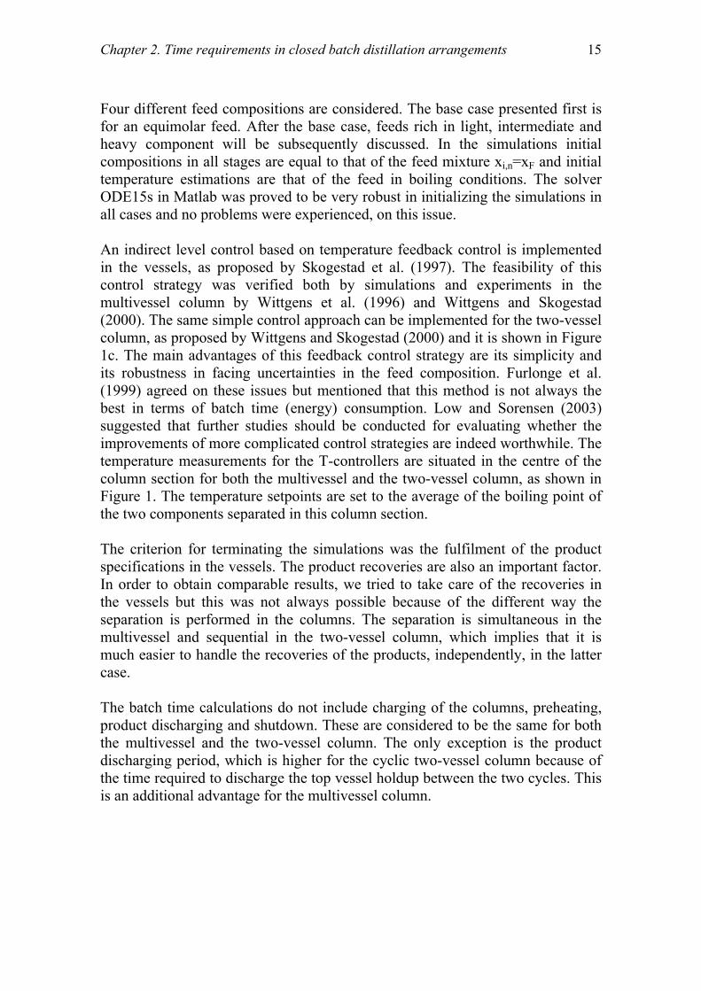
Chapter 2. Time requirements in closed batch distillation arrangements 15
Four different feed compositions are considered. The base case presented first is for an equimolar feed. After the base case, feeds rich in light, intermediate and heavy component will be subsequently discussed. In the simulations initial compositions in all stages are equal to that of the feed mixture xi,n=xF and initial temperature estimations are that of the feed in boiling conditions. The solver ODE15s in Matlab was proved to be very robust in initializing the simulations in all cases and no problems were experienced, on this issue. An indirect level control based on temperature feedback control is implemented in the vessels, as proposed by Skogestad et al. (1997). The feasibility of this control strategy was verified both by simulations and experiments in the multivessel column by Wittgens et al. (1996) and Wittgens and Skogestad (2000). The same simple control approach can be implemented for the two-vessel column, as proposed by Wittgens and Skogestad (2000) and it is shown in Figure 1c. The main advantages of this feedback control strategy are its simplicity and its robustness in facing uncertainties in the feed composition. Furlonge et al. (1999) agreed on these issues but mentioned that this method is not always the best in terms of batch time (energy) consumption. Low and Sorensen (2003) suggested that further studies should be conducted for evaluating whether the improvements of more complicated control strategies are indeed worthwhile. The temperature measurements for the T-controllers are situated in the centre of the column section for both the multivessel and the two-vessel column, as shown in Figure 1. The temperature setpoints are set to the average of the boiling point of the two components separated in this column section. The criterion for terminating the simulations was the fulfilment of the product specifications in the vessels. The product recoveries are also an important factor. In order to obtain comparable results, we tried to take care of the recoveries in the vessels but this was not always possible because of the different way the separation is performed in the columns. The separation is simultaneous in the multivessel and sequential in the two-vessel column, which implies that it is much easier to handle the recoveries of the products, independently, in the latter case. The batch time calculations do not include charging of the columns, preheating, product discharging and shutdown. These are considered to be the same for both the multivessel and the two-vessel column. The only exception is the product discharging period, which is higher for the cyclic two-vessel column because of the time required to discharge the top vessel holdup between the two cycles. This is an additional advantage for the multivessel column.

16
3. Results
3.1 Base case - equimolar feed
The system methanol/ethanol/1-propanol is studied. An equimolar feed F with composition xF=[1/3,1/3,1/3], mainly placed in the reboiler, is considered and will be used as the base case in this work. Since this system exhibits no azeotropic behaviour, the separation is proceeding according to the boiling temperatures of the components. In the conventional multivessel column (Fig. 1a) the mixture is separated simultaneously in one closed operation. The three components are accumulated in the vessels at the end of the process. Methanol is the light component and is recovered in the top vessel, while ethanol and 1-propanol are the intermediate and heavy components recovered in the middle and bottom vessel, respectively. Figure 2 shows how the separation is evolving with time. The top vessel is steadily enriched in methanol, the middle vessel in ethanol and the propanol is staying in the bottom vessel. The final column liquid profile is also shown with open circles. The rectifying (top) section of the column is performing the binary separation between methanol and ethanol. The top section liquid profile is therefore in the binary edge between methanol and ethanol. The stripping (bottom) section of the column is performing the binary separation between ethanol and 1-propanol and the bottom liquid profile in mainly in the binary edge between these two components. The separation is performed exactly in the same way in the modified multivessel column (Fig. 1b). One closed operation is needed and the final products are simultaneously accumulated in the vessels. The reason for investigating this multivessel configuration will become evident later after the analysis of the dynamics in the vessels.
In the two-vessel column (Fig. 1c) the separation is proceeding differently. The column has two vessels, and thus, it is not possible to separate all three components simultaneously. Two closed operations, which will be called cycles hereafter, are needed and the separation resembles the direct split in continuous columns. During Cycle 1 the light component (methanol) is accumulated in the top vessel, as shown in Fig. 3a. The still (bottom vessel) is following a linear path away from the component (methanol) accumulated in the top vessel. Cycle 1 is terminated when the specification for methanol is fulfilled. Then the vessel is emptied and the accumulated methanol is discharged in the product tank, instantaneously. A small amount of methanol still remains in the column and can

Chapter 2. Time requirements in closed batch distillation arrangements 17
contaminate the future products. Thus, an off-cut fraction has to be removed between the two cycles. This is done by a closed operation of the column for a short time using the same control parameters as for the second cycle. The off-cut fraction is equal to the total column holdup (0.1 kmol). Cycle 2 is, then, an almost binary separation of the two components (ethanol and 1-propanol) left in the still after the off-cut fraction (xF2 in Fig. 3a). The intermediate component (ethanol) is accumulated in the top vessel, while the heaviest one (1-propanol) remains in the still, as shown in Fig. 3b. The simulations were terminated when the composition specifications for all the products in the vessels were fulfilled. Results are provided for three specification sets. xspec,1 = [0.99, 0.97, 0.99], xspec,2 = [0.99, 0.99, 0.99] and xspec,3 = [0.995, 0.995, 0.995]. In the second set, the specification in the middle vessel is stricter (0.97 to 0.99). In the third set the specifications are tighter in all vessels (0.99 to 0.995). The batch time comparisons are summarized in Table 1. The time requirements in the conventional multivessel are used as a basis for the comparisons. A positive sign (+) in Table 1 indicates longer process times compared to the conventional multivessel. A negative sign (-) indicates shorter process times (time savings).
Methanol [un]64.6 oC
Ethanol [s]78.3 oC
1-Propanol [sn]97.8 oC
F
xT
xB xM
top vessel
bottom vesselmiddle vessel
-o-o- column liquid profile
...... composition evolution
Fig. 2: Simultaneous separation of a zeotropic mixture in the multivessel column

18
Methanol [un]64.6 oC
Ethanol [s]78.3 oC
1-Propanol [sn]97.8 oC
F
xT
xB
top vessel
still pathCYCLE 1
-o-o- column liquid profile
....... composition evolution
a)
Methanol [un]64.6 oC
Ethanol [s]78.3 oC
1-Propanol [sn]97.8 oC
xF2 xTxB
top vesselstill path
CYCLE 2
-o-o- column liquid profile
....... composition evolution
b)
Fig. 3: Sequential separation of a zeotropic mixture in the two-vessel column a) Cycle 1: recovering the methanol in the top vessel b) Cycle 2: recovering the ethanol in the top vessel and the propanol in the still

Chapter 2. Time requirements in closed batch distillation arrangements 19
Table 1: Time requirements and time savings (basis: conventional multivessel)
Specification
Conventional multivessel (with vapour
bypass)
[h]
Modified multivessel (no vapour
bypass)
[%]
Two-vessel column
[%]
[0.99,0.97,0.99]
3.8
-26
+32
[0.99,0.99,0.99]
4.9 -31 +16
Base case-Equimolar
xF=[1/3,1/3,1/3] [0.995,0.995,0.995]
5.8 -33 +16
[0.99,0.97,0.99]
3.6
-19
+8
[0.99,0.99,0.99]
4.1 -22 +2 Rich in light
xF=[0.7,0.15,0.15]
[0.995,0.995,0.995]
4.5
-22 +2
[0.99,0.97,0.99]
4.0
-33
+28
[0.99,0.99,0.99]
6.6 -36 -2
Rich in
intermediate
xF=[0.15,0.7,0.15] [0.995,0.995,0.995]
7.9
-34 -8
[0.99,0.97,0.99]
2.4
0
+71
[0.99,0.99,0.99]
2.4 0 +104 Rich in heavy
xF=[0.15,0.15,0.7]
[0.995,0.995,0.995]
2.8
0 +104

20
Conventional multivessel vs. two-vessel column
The batch time comparisons in Table 1 show that the conventional multivessel performs always better than the two-vessel column for equimolar feeds. The two-vessel column requires from 16% to 32% more time than the multivessel in order to perform the same separation. The most important difference is that the separation is performed simultaneously in the multivessel, in contrast to the two-vessel column, where two closed operations are required. The time advantages of the multivessel column are becoming smaller, as the specification in the middle vessel becomes stricter. For example, when the specification in the middle vessel increases from 0.97 to 0.99, the time advantages of the multivessel decrease from 32% to 16%. However, when the specification becomes strict in all vessels (third specification set) no more time gains can be expected for the two-vessel column. This happens because the increase in the separation time for the multivessel column, from 4.9h to 5.8h, is outweighed by a proportionally equal increase mainly in Cycle 1 of the two-vessel column. Cycle 1 has to be run for longer time in order to achieve the strict specification of 0.995 for the methanol in the top vessel.
Conventional multivessel vs. modified multivessel
Table 1 shows clearly that the elimination of the vapour bypass in the multivessel column has a great effect in the batch time (energy) requirements. The modified multivessel is always faster than the conventional multivessel for equimolar feeds. The time savings vary from 26% to 33% depending on the specification, which indicate a rather weak dependence. In average, the modified multivessel exhibits time advantages of around 30% over the conventional multivessel.
This is a rather surprising result since one would expect minor differences, mainly attributed to the one additional equilibrium stage of the modified multivessel compared to the conventional. However, the situation is a bit more complicated. The middle vessel should not be considered simply as an additional equilibrium stage. It has a larger holdup compared to the stages inside the column and the dynamics in the vessels are playing a decisive role in the separation time requirements. Fig. 4 illustrates what is happening in the vessels of the multivessel during the process. Figure 4a shows the composition dynamics of the main component in each vessel for the conventional multivessel. The case of the first specification test [0.99,0.97,0.99] is considered. The methanol in the top vessel reaches the specification very fast, after 0.5h, mainly because of the very small amount of initial holdup in the vessel. The bottom vessel is responding slowly the first 1 hour. This is because it carries 94% of the total feed. However, the evolution is

Chapter 2. Time requirements in closed batch distillation arrangements 21
almost exponential after the first hour and finally, the propanol reaches its specification after 2.5hr. The middle vessel, which has the lowest specification, exhibits the slowest dynamics. It takes actually 3.8hr for ethanol to reach its low specification (0.97). At this time, all specifications are met and the separation task is ended. It is clear that the dynamics of the middle vessel are decisive for the whole process. Fig. 4b provides even more insight into the process. The composition dynamics of the light component (methanol) in all vessels are shown. We see that the light methanol starts accumulating very fast in the top vessel and it is depleted rather fast (practically after 1.5h) from the bottom vessel. However, the methanol insists on appearing in the middle vessel, which indicates an inherent inability of the middle vessel to “boil-off” the light component. The light component is in a sense trapped in the middle vessel and the process is significantly delayed. Why this is happening is becoming clear by looking in the design characteristics of the conventional multivessel in Fig. 1a. The vapour bypass from the stripping section to the rectifying section of the column is responsible for this. The light component in the middle vessel is depleted slowly because there is no vapour phase coming in contact with the liquid holdup in it. This disadvantage of the conventional multivessel is removed in the so-called modified multivessel, where the vapour stream from the stripping section enters the middle vessel. The effect of the elimination of the vapour bypass is obvious in Fig. 4c, where the evolution of the compositions in the middle vessel is shown for both the conventional and the modified multivessel. The methanol is boiled-off faster when there is no vapour bypass and the main component (ethanol for the middle vessel) is reaching its specification faster. Almost 30% less time is required for performing this separation in the modified multivessel compared to the conventional one.

22
0 0.5 1 1.5 2 2.5 3 3.5 40.3
0.4
0.5
0.6
0.7
0.8
0.9
1
Time (h)
com
posit
ion
of m
ain
com
pone
nt
top vessel bottom vesselmiddle vessel
a)
0 0.5 1 1.5 2 2.5 3 3.5 40
0.1
0.2
0.3
0.4
0.5
0.6
0.7
0.8
0.9
1
Time (h)
com
posit
ion
of li
ght c
ompo
nent
top vessel
middle vessel
bottom vessel
b)
0 0.5 1 1.5 2 2.5 3 3.5 40
0.1
0.2
0.3
0.4
0.5
0.6
0.7
0.8
0.9
1
Time (h)
com
posit
ion
in th
e m
iddl
e ve
ssel
ethanol
methanol1-propanol
______ conventional multivessel
............. modified multivessel
c)
Fig. 4: Composition dynamics in the vessels of a) conventional multivessel; b) conventional multivessel; c) conventional and modified multivessel

Chapter 2. Time requirements in closed batch distillation arrangements 23
Discussion
In Fig. 4c it is obvious that the elimination of the vapour bypass has negligible effect in the composition dynamics of the heavy component (1-propanol). This is reasonable since the liquid flow out from the middle vessel remains almost unchanged in the two multivessel configurations. The problem however can be important in liquid bypass configurations (Warter and Stichlmair, 1999). In this case, we would observe the reverse situation. The heavy component, entering the middle vessel, will be “trapped” there and will be stripped down in the column in a slow rate. The results presented in Hasebe et al. (1995) and Skogestad et al. (1997) indicate the slow dynamics in the middle vessel. In Fig. 7 of Hasebe et al. (1995) the middle vessel product satisfies its specification last. Skogestad et al. (1997) provided simulated results for a quaternary mixture in a multivessel column with four vessels. In Figs. 3b and 4b of this work the light impurities in the two middle vessels persist for long time, thus delaying the process. The elimination of the vapour bypass enhances the composition dynamics in the middle vessel, thus making the process faster. Low and Sorensen (2002) studied the optimal operation of the rectifier and the multivessel column for the separation of an azeotropic mixture by extractive distillation. Different configurations of the vapour stream in the middle section of the multivessel column were included in their study. The authors mention “the performance of the middle-vessel column is significantly influenced by the middle-section stream configuration”. The comparison of the conventional and the modified multivessel showed that the latter performs better that the former in terms of process time, overall heat duty and product recoveries. In the work of Hasebe, a set of existing batch rectifiers connected sequentially is proposed for a practical realization of the multivessel column. In this case it would be impractical to eliminate the vapour bypass since this will require significant changes in the existing rectifier columns. Nevertheless, in the case of a new multivessel column, built from scratch, the configuration with no vapour bypass would be the best choice. Practical difficulties related to the diversion of the vapour stream into a heated middle vessel for the modified multivessel were also mentioned by Low and Sorensen (2002). The knowledge of the slow dynamics in the middle vessel can serve as a very simple guideline for the initial feed distribution in the vessels. If the objective is to minimize batch time (energy demand) the advice we give is not to place the feed in the middle vessel. In such a case, e.g. placing the feed in the middle vessel, the dynamic response of the vessel would be even slower, because of the large holdup to be accomplished and the large amount of light component that

24
has to be boiled off in a slow rate. Hilmen (2000) supports this simple intuitive guideline. “For medium difficulty separations…charging the feed to the intermediate vessel was worst in all cases of feed composition” and “…for easy separations we found large time savings for feeds charged to the reboiler instead of the middle vessel”. In contrast, for difficult separations the initial distribution of the feed is not very important anymore. This happens because the actual batch time is determined by the difficulty of the separation task itself and not by the dynamics of the vessels. In conclusion, the results for the base case indicate that the modified multivessel is the best alternative. The modified column requires 30% less time than the conventional one. By comparing now the two-vessel column with the modified multivessel, we see that the former requires around 70% more time than the latter for the same separation. 3.2 Effect of the feed composition
Feed rich in light component
For a feed rich in the light component xF=[0.7,015,0.15] the results in Table 1 reveal that the elimination of the vapour bypass is advantageous also in this case. The modified multivessel requires around 20% less time than the conventional multivessel and the time savings are independent of the specification. The striking result for such feeds is the minor advantages of the multivessel column compared to the two-vessel column, which is marginally slower (8%-2%) than the multivessel. This result is in agreement with the results presented by Hilmen, (2000) that mentions “for medium difficult separations, the benefits of the multivessel column are low for feeds rich in light components and feed low in heavy component”. The comparison in Hilmen, (2000) refers to the indirect split but our results show that it holds also for the direct split. However, we see that there is a potential to save separation time (energy) by using multivessel configurations as long as the modified multivessel is employed, instead of the conventional one. Then, the potential savings in the modified multivessel compared to the two-vessel are around 25%.

Chapter 2. Time requirements in closed batch distillation arrangements 25
Feed rich in intermediate component
Intuitively, the results for this case should reflect the fact that the middle vessel has slow dynamics and delays the separation task in multivessel configurations. The results in Table 1 for a feed xF=[0.15,0.7,0.15] support our intuition. The first thing to observe is the increase in the separation time values for the conventional multivessel. Notice, for example, the time requirements for the second specification set for different feeds xF. The actual separation times increase from 4.1h to 4.9h and finally to 6.6h, as the intermediate component increase in the feed from 0.15 to 1/3 and to 0.7. This happens because of the large amount of intermediate component accumulated in the middle vessel during the process. The middle vessel has anyway very slow dynamics and the large holdup to be processed in the vessel is making the situation even worse. As expected, the elimination of the vapour bypass is very effective in this case. The modified multivessel requires around 35% less time than the conventional one and this is the maximum time savings observed with the modified configuration, in this study. Consequently, the modified multivessel is strongly recommended for such feeds. The comparison between the conventional multivessel and the two-vessel column is in favour of the former only for the first specification set. When the specifications become stricter in the middle vessel (from 0.97 to 0.99) or to all the vessels (from 0.99 to 0.995), the two-vessel column requires slightly less time (2% to 8%) compared to the conventional multivessel. The same was mentioned by Meski et al. (1998), who compared the multivessel column with the direct and indirect split (or combinations) in regular batch columns. They found that regular columns (e.g. the two-vessel column) were best for feeds rich in the intermediate component. In contrast, Hasebe et al. (1992) claimed that the multivessel column is more effective in removing light and heavy impurities from a feed than ordinary distillation. Our results, certainly do not support such a statement, neither do the results from Meski et al. (1998) and Hilmen (2000). By comparing now the modified multivessel with the two-vessel column we see that even in this case, which is the worst one for the conventional multivessel, the modified multivessel is superior and requires around 35% less time than the two-vessel column.

26
Feed rich in heavy component
The results for this last case, for feed xF=[0.15,0.15,0.7], are very interesting. This case represents the “ultimate” situation for multivessel configurations. The last rows in Table 1 show that the separation task is accomplished very fast in the conventional multivessel. It takes only 2.4h (for the second specification set) for the separation to be finished compared to 6.6h or 4.9hr or 4.1h in previous cases. The explanation for these numbers is that the separation is governed by the dynamics of the bottom vessel. The middle vessel is not anymore the slowest vessel and therefore the inherent disadvantage of the middle vessel is vanishing. The fact that the middle vessel dynamics are playing no role in this case is illustrated clearly by the zero time savings of the modified multivessel. The elimination of the vapour bypass has no effect in the separation task, which is determined by the bottom vessel dynamics. The comparison between the conventional multivessel and the two-vessel column is strongly in favour of the former. The cyclic column requires from 70% to 104% more time depending on the specification. In addition, as the specification becomes stricter the results are even worse for the two-vessel column. Hilmen (2000) also mentioned that large time savings are expected for the multivessel column compared to the two-vessel column for medium difficult and feeds rich in heavy components. Sorensen and Prenzler (1997) mention that this is a common separation task in the pharmaceutical and fine chemical industries where light solvents should be recovered from waste water streams and the specifications are very tight (few ppm for the solvent). The common practice is to perform these separations sequentially in conventional batch rectifiers. However, as the results indicate here, a multivessel configuration of serially connected existing rectifiers is actually a much better alternative. The potential time (energy) savings of such a rearrangement of existing rectifiers in the plant are remarkable (50%) and indicate that valuable process time can be saved without too much effort.

Chapter 2. Time requirements in closed batch distillation arrangements 27
4. Conclusions
Batch time requirements, based on dynamic simulations of the process, were provided for the separation of a zeotropic mixture in closed batch distillation arrangements. The batch arrangements studied were a conventional multivessel column with a vapour bypass, a modified multivessel without a vapour bypass and a two-vessel column (rectifier). The task was to separate a mixture of methanol/ethanol/1-propanol. The base case of equimolar feed was used for illustrating an important disadvantage of conventional multivessel configurations, namely, the slow dynamics in the middle vessel. Elimination of the vapour bypass in the middle was proposed and the results for the so-called modified multivessel supported this intuitive design modification. Multivessel configurations, either conventional or modified, perform always better than traditional configurations like the two-vessel column. In the comparison between the modified multivessel (without vapour bypass) and the conventional multivessel (with vapour bypass), the former is superior to the latter, with the exception of feeds rich in heavy components where no differences are noticed in the time requirements. The conventional multivessel performs worst for feeds rich in the intermediate component. This is the only case where the two-vessel column is slightly faster (2% to 8%) and reflects the slow dynamic response of the middle vessel. However, even in this case, the modified multivessel is the best alternative. Feeds rich in the heavy component are the ultimate case for multivessel configurations. The potential time savings of processing such feeds in multivessel configurations instead of in regular batch columns are around 50%. This result should be of great practical importance in the pharmaceutical, fine and specialty chemicals industries.

28
5. Notation
α Relative volatility vector F Feed [kmol] Lbot Liquid flows in the stripping section [kmol h-1] Ltop Liquid flows in the rectifying section [kmol h-1] nC Number of components nN Number of total stages nV Number of vessels Nr Number of stages in the rectifying section Ns Number of stages in the stripping section (s) Saddle point (sn) Stable node TC Temperature controller (un) Unstable node V Vapour flows (molar boilup) [kmol h-1] V/F Ratio of the molar boilup over the initial feed [h-1] xB Bottom vessel composition xF Feed composition xF2 Composition at the beginning of Cycle 2 xi,n Composition in each stage xM Middle vessel composition xspec,1 Specification set 1 xspec,2 Specification set 2 xspec,3 Specification set 3 xT Top vessel composition

Chapter 2. Time requirements in closed batch distillation arrangements 29
APPENDIX
Table A1: Column data for the simulations
Conventional multivessel
Modified multivessel
Two-vessel column
Stages per section Nr = 25, Ns = 25 Nr = 25, Ns = 24 Ntotal = 50 Initial feed MF = 5.385 kmol MF = 5.385 kmol MF = 5.385 kmol Initial condenser holdup MT0 = 0.035 kmol MT0 = 0.035 kmol MT0 = 0.035 kmol Initial middle vessel holdup MF0 = 0.250 kmol MF0 = 0.250 kmol No middle vessel Initial reboiler holdup MB0 = 5.000 kmol MB0 = 5.000 kmol MB0 = 5.250 kmol Trays holdup Mi = 1/500 kmol Mi = 1/500 kmol Mi = 1/500 kmol Vapour flow V = 5 kmol h-1 V = 5 kmol h-1 V = 5 kmol h-1
Table A2: Controller data
Controller gain for the rectifying section or cycle 1
Kc = 0.365 kmol (h ºC)-1
Controller gain for the stripping section or cycle 2
Kc = 0.256 kmol (h ºC)-1
Temperature setpoint for the rectifying section or cycle 1
Tsp = 71.45 ºC
Temperature setpoint for the stripping section or cycle 2
Tsp = 88.05 ºC
Table A3: Thermodynamic data for methanol/ethanol/1-propanol (Gmehling and Onken, 1977)
methanol (1) / ethanol (2) / 1-propanol (3) Antoine equation A B C
1 8.08097 1582.271 239.726 2 8.11220 1592.864 226.184 3 8.37895 1788.020 227.438
NRTL Aij (cal/mol) Aji (cal/mol) aij=aji 1-2 67.2902 -70.5092 0.3009 1-3 144.4797 -12.7427 0.3067 2-3 -2.5594 56.2391 0.3007

30
6. References
Furlonge, H.I., Pantelides, C.C., Sorensen, E., (1999), Optimal operation of multivessel batch distillation columns, AIChE J, 45 (4), 781-801. Gmehling, J., Onken, J., (1977), Vapour-liquid equilibrium data collection, DECHEMA Chemistry Data Series, Frankfurt am Main. Hasebe, S., Abdul Aziz, B. B., Hashimoto, I., Watanabe, T., (1992), Optimal design and operation of complex batch distillation column, Proceedings of the IFAC Workshop on Interaction between Process Design and Process Control (pp. 177-182), London, UK. Hasebe, S., Kurooka, T., Hashimoto, I., (1995), Comparison of the separation performances of a multi-effect batch distillation system and a continuous distillation system, Proceedings of the IFAC Symposium on DYCORD+’95 (pp.249-254), Elsingore, Denmark: Pergamon press. Hasebe, S., Noda, M., Hashimoto, I., (1997), Optimal operation policy for multi-effect batch distillation system, Computers and Chemical Engineering (Suppl.), 21S, S1221. Hasebe, S., Noda, M., Hashimoto, I., (1999), Optimal operation policy for total reflux and multi-effect batch distillation systems, Computers and Chemical Engineering, 23, 523-532. Hilmen, E. K., (2000), Separation of azeotropic mixtures: tools for analysis and studies on batch distillation operation, PhD Thesis (Chapter 6), NTNU, Norway. Low, K.H., Sorensen, E., (2002), Optimal operation of extractive distillation in different batch configurations, AIChE J., 48 (5), 1034. Low, K.H., Sorensen, E., (2003), Simultaneous optimal design and operation of multivessel batch distillation, AIChE J., 49 (10), 2564. Low, K.H., Sorensen, E., (2004), Simultaneous optimal design and operation of multipurpose batch distillation columns, Chemical Engineering and Processing (Special Issue: Distillation & Absorption), 43 (3), 273. Meski, G.A., Han, M., Bekiaris, N., Morari, M., (1998), Optimality for batch distillation configurations, Proceedings of the IFAC Symposium on DYCOPS-5 (pp. 387-392), Corfu, Greece, 8-19 June 1998.

Chapter 2. Time requirements in closed batch distillation arrangements 31
Noda, M., Kato, A., Hasebe, S., Hashimoto, I., (1999), Optimal structure of batch distillation column, Computers and Chemical Engineering (Suppl.), S105-S108. Robinson C.S., Gilliland, E.R., (1950), Elements of fractional distillation, Vol. 4, McGraw Hill, New York. Skogestad, S., Wittgens, B., Litto, R., Sorensen, E., (1997), Multivessel batch distillation, AIChE J., 43 (4), 971-978. Sorensen, E., Prenzler, M., (1997), A cyclic operating policy for batch distillation- theory and practice, Computers and Chemical Engineering, S21, S1215-S1220. Sorensen, E., Skogestad, S., (1994), Optimal operating policies of batch distillation with emphasis on the cyclic operating policy, Proceedings of the 5th International symposium on Process Systems Engineering (PSE ’94), 449-456. Warter, M., Stichlmair, J., (1999), Batchwise extractive distillation in a column with a middle vessel, Computers and Chemical Engineering (Suppl.), S23, S915-S918. Wittgens, B., Litto, R., Sorensen, E., Skogestad, S., (1996), Total reflux operation of multivessel batch distillation, Computers and Chemical Engineering (Suppl.), S20, S1041-1046. Wittgens, B., Skogestad, S., (1998), Multivessel batch distillation-potential energy savings, Proceedings of the IFAC Symposium DYCOPS-5 (pp. 515-520), Greece. Wittgens, B., (1999), Experimental verification of dynamic operation of continuous and multivessel batch distillation, PhD Thesis (Chapter 6), NTNU, Norway. Wittgens, B., Skogestad, S., (2000), Closed operation of multivessel batch distillation: experimental verification, AIChE J., 46 (6), 1209-1217.


Chapter 3
SEPARATION OF TERNARY HETEROAZEOTROPIC
MIXTURES IN A CLOSED MULTIVESSEL BATCH
DISTILLATION-DECANTER HYBRID S. Skouras, S. Skogestad
Norwegian University of Science & Technology, Department of Chemical
Engineering, Sem Saelandsvei 4, 7491, Trondheim, Norway
Preliminary version of this paper presented in
19th European Seminar on Applied Thermodynamics, Santorini, Greece, 6-10 September, 2002
and International Conference on Distillation & Absorption, Baden-Baden, Germany, 30
September-2 October 2002
This paper was published in
Chemical Engineering and Processing, 43 (3), (2004), 263-272
Abstract
The feasibility of a novel multivessel batch distillation-decanter hybrid for separation of ternary heterogeneous azeotropic mixtures is addressed. The hybrid column is operated as a closed system without product withdrawal and the products are accumulated in the vessels during one closed operation. Part of the separation is performed by distillation, while the liquid-liquid split in the decanter is used for crossing the distillation boundaries. At the end of the process, two pure components are recovered in the vessels and a phase rich in the third component is recovered in the decanter. Heteroazeotropic mixtures classified under Serafimov’s classes 1.0-2, 1.0-1a and 2.0-2b are studied. As a first approach, only information coming from the distillation line map and the binodal curve of the mixtures is used and the separation process is described qualitatively. Later on, dynamic simulations verified the feasibility of the separation process in the hybrid column.
34
1. Introduction
1.1 Previous work on the multivessel column
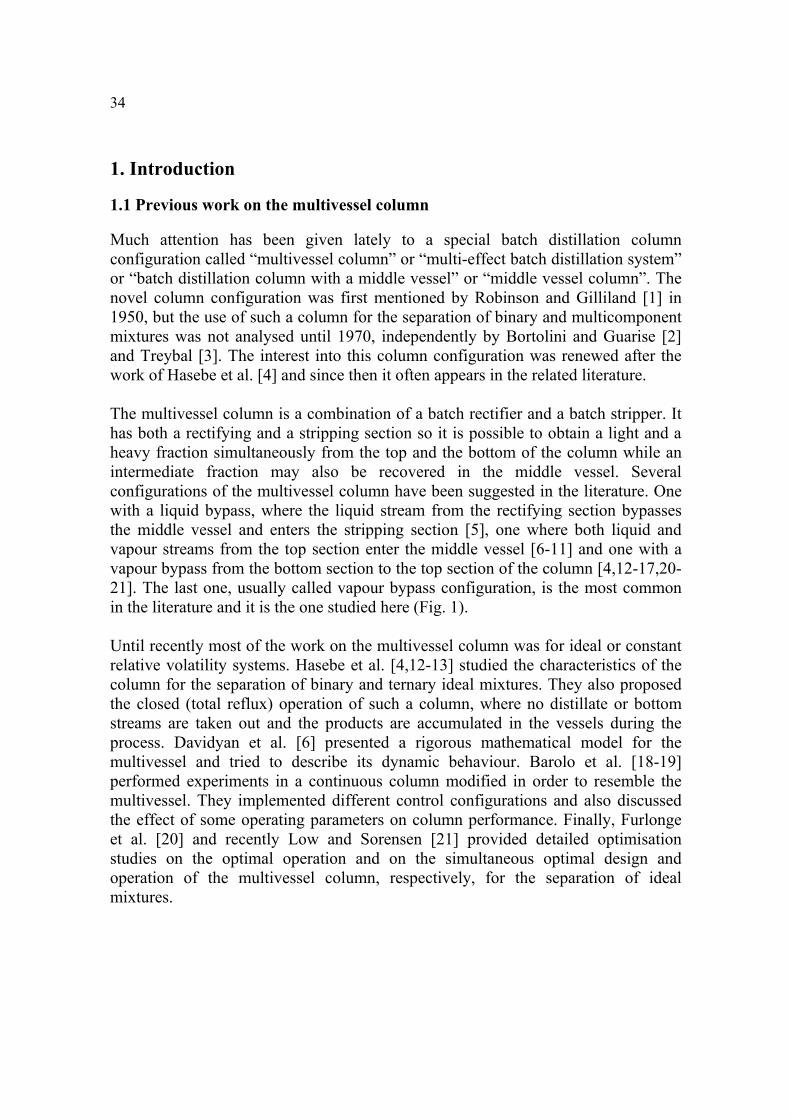
Much attention has been given lately to a special batch distillation column configuration called “multivessel column” or “multi-effect batch distillation system” or “batch distillation column with a middle vessel” or “middle vessel column”. The novel column configuration was first mentioned by Robinson and Gilliland [1] in 1950, but the use of such a column for the separation of binary and multicomponent mixtures was not analysed until 1970, independently by Bortolini and Guarise [2] and Treybal [3]. The interest into this column configuration was renewed after the work of Hasebe et al. [4] and since then it often appears in the related literature.
The multivessel column is a combination of a batch rectifier and a batch stripper. It has both a rectifying and a stripping section so it is possible to obtain a light and a heavy fraction simultaneously from the top and the bottom of the column while an intermediate fraction may also be recovered in the middle vessel. Several configurations of the multivessel column have been suggested in the literature. One with a liquid bypass, where the liquid stream from the rectifying section bypasses the middle vessel and enters the stripping section [5], one where both liquid and vapour streams from the top section enter the middle vessel [6-11] and one with a vapour bypass from the bottom section to the top section of the column [4,12-17,20-21]. The last one, usually called vapour bypass configuration, is the most common in the literature and it is the one studied here (Fig. 1). Until recently most of the work on the multivessel column was for ideal or constant relative volatility systems. Hasebe et al. [4,12-13] studied the characteristics of the column for the separation of binary and ternary ideal mixtures. They also proposed the closed (total reflux) operation of such a column, where no distillate or bottom streams are taken out and the products are accumulated in the vessels during the process. Davidyan et al. [6] presented a rigorous mathematical model for the multivessel and tried to describe its dynamic behaviour. Barolo et al. [18-19] performed experiments in a continuous column modified in order to resemble the multivessel. They implemented different control configurations and also discussed the effect of some operating parameters on column performance. Finally, Furlonge et al. [20] and recently Low and Sorensen [21] provided detailed optimisation studies on the optimal operation and on the simultaneous optimal design and operation of the multivessel column, respectively, for the separation of ideal mixtures.

Chapter 3. Separation of ternary heteroazeotropic mixtures in a closed multivessel batch distillation-decanter hybrid
35
For the closed operation of the multivessel column, with product accumulation in the vessels, a simple feedback control structure, based on temperature controllers, was proposed by Skogestad et al. [14]. The liquid flow rates out of each vessel are adjusted based on a temperature measurement in the middle of the column section below each vessel, as shown in Fig. 1. The temperature setpoints are simply taken as the average of the boiling points of the two components separated in this section. The feasibility of this simple control strategy was demonstrated both by simulations and experiments by Wittgens et al. [15] and Wittgens and Skogestad [16], respectively. A constant relative volatility quaternary system was studied and at the end of the process four pure products were accumulated at the vessels. This control strategy is very simple and it is also proved to be robust and achieved high purity products independent of uncertainties in the feed composition.
Fig. 1: The multivessel batch column with the vapour bypass in the middle vessel

36
The first who studied the performance of the multivessel column in the separation of azeotropic mixtures was Safrit et al. [7,8]. The case of extractive batch distillation with a heavy entrainer continuously added from the top of the multivessel column was investigated. Warter and Stichlmair [5] and Hilmen et al. [17] reported some advantages of this novel process over conventional extractive batch distillation. Recently, Warter et al. [22] showed experimental results on extractive distillation in the multivessel column for the separation water-ethanol when ethylene glycol was used as entrainer. In a series of papers Cheong and Barton [9-11] developed a mathematical model in order to study the qualitative dynamics of the multivessel column for the separation of homogeneous azeotropic mixtures. The theoretical insights from the analytical tools developed, were also verified by simulations. Warter and Stichlmair [23] have also showed simulated results for the separation of binary azeotropic mixtures by using homogeneous entrainers, which are added batchwise in the original mixture. They showed ways to cross the distillation boundaries by placing the feed at the concave side of the boundary and by manipulating the vapour flows in the two sections of the column. In this way all three original components were recovered in pure form. Hilmen [24] provided also simulated results on the closed multivessel batch distillation of ternary homogeneous azeotropic mixtures when the control strategy by Skogestad et al. [14] was implemented. Finally, Rodriguez et al. [25] showed results when heterogeneous entrainers (heteroazeotropic distillation) were used instead. The column was operated as an open system with product withdrawal from the top and bottom vessel and a decanter was combined with the multivessel column for performing the liquid-liquid split, in a distillation-decanter hybrid.
1.2 Previous work on azeotropic mixtures
Throughout this work, ideas and results presented by Kiva et al. [26] and Hilmen et al. [27] are frequently cited and used. These two papers contain results on azeotropic mixtures from the Russian literature, which are very little known in the West. Two important issues from these papers are often used in this study. The first issue is Serafimov’s classification for azeotropic systems. Most of the people in the West are familiar with the classification of azeotropic mixtures in 113 classes proposed by Matsuyama and Nishimura in 1977 [28], later extended to 125 classes after the work by Foucher et al. [29]. This classification was recently included also in Perry’s chemical engineering handbook [30]. However, after the work of Kiva et al. [26] and Hilmen et al. [27] it became known that in the former Soviet Union a complete classification of feasible VLE structures for ternary systems was presented already in 1970. Serafimov showed that the feasible
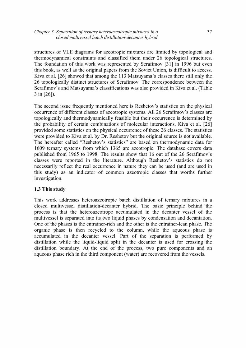
Chapter 3. Separation of ternary heteroazeotropic mixtures in a closed multivessel batch distillation-decanter hybrid
37
structures of VLE diagrams for azeotropic mixtures are limited by topological and thermodynamical constraints and classified them under 26 topological structures. The foundation of this work was represented by Serafimov [31] in 1996 but even this book, as well as the original papers from the Soviet Union, is difficult to access. Kiva et al. [26] showed that among the 113 Matsuyama’s classes there still only the 26 topologically distinct structures of Serafimov. The correspondence between the Serafimov’s and Matsuyama’s classifications was also provided in Kiva et al. (Table 3 in [26]). The second issue frequently mentioned here is Reshetov’s statistics on the physical occurrence of different classes of azeotropic systems. All 26 Serafimov’s classes are topologically and thermodynamically feasible but their occurrence is determined by the probability of certain combinations of molecular interactions. Kiva et al. [26] provided some statistics on the physical occurrence of these 26 classes. The statistics were provided to Kiva et al. by Dr. Reshetov but the original source is not available. The hereafter called “Reshetov’s statistics” are based on thermodynamic data for 1609 ternary systems from which 1365 are azeotropic. The database covers data published from 1965 to 1998. The results show that 16 out of the 26 Serafimov’s classes were reported in the literature. Although Reshetov’s statistics do not necessarily reflect the real occurrence in nature they can be used (and are used in this study) as an indicator of common azeotropic classes that worths further investigation.
1.3 This study
This work addresses heteroazeotropic batch distillation of ternary mixtures in a closed multivessel distillation-decanter hybrid. The basic principle behind the process is that the heteroazeotrope accumulated in the decanter vessel of the multivessel is separated into its two liquid phases by condensation and decantation. One of the phases is the entrainer-rich and the other is the entrainer-lean phase. The organic phase is then recycled to the column, while the aqueous phase is accumulated in the decanter vessel. Part of the separation is performed by distillation while the liquid-liquid split in the decanter is used for crossing the distillation boundary. At the end of the process, two pure components and an aqueous phase rich in the third component (water) are recovered from the vessels.

38
Fig. 2: Serafimov’s 26 topological classes and Reshetov’s statistics (o) unstable node, (∆) saddle, (●) stable node. (Reprinted from Hilmen et al. [27])

Chapter 3. Separation of ternary heteroazeotropic mixtures in a closed multivessel batch distillation-decanter hybrid
39
Three classes of azeotropic mixtures, namely Serafimov’s classes 1.0-2, 1.0-1a and 2.0-2b are studied here. Each one of them represents a class of azeotropic systems frequently found in nature, according to Reshetov’s statistics. Thus, the first system studied, namely class 1.0-2, corresponds to class 020 and 400 of Matsuyama’s classification and represents 8.5% of the azeotropic mixtures reported in the literature. The second system of class 1.0-1a, corresponds to Matsuyama’s class 100 and 030 and represents 21.6% of the azeotropic systems reported. Finally, the third system is that of class 2.0-2b or class 102, 120 and 021 according to Matsuyama and Nishimura and represents 21% of all azeotropic systems. In total, the three classes represent more than half (51.1%) of all azeotropic systems reported, which simply indicates the practical importance of this study. It should be noted that the work of Serafimov is for homogeneous mixtures. To the best of our knowledge, a classification specifically for heterogeneous azeotropic mixtures has not been conducted yet. However, as noted by Kiva et al. [26], the topology of a residue curve (or a distillation line) map of a heterogeneous mixture does not differ from that of a homogeneous mixture with the same set of stationary points. The main difference between heterogeneous and homogeneous mixtures is that a heteroazeotrope can only be a minimum-boiling azeotrope, while a homogeneous azeotrope can be either minimum-boiling or maximum-boiling azeotrope. Thus, a heteroazeotrope can be either unstable node or saddle and can never be a stable node. Therefore, Serafimov’s classification is valid also for heterogeneous mixtures but someone should always keep in mind that a maximum-boiling azeotrope could never be a heterogeneous one. The rest of the paper is structured as follows. First, the mixtures studied (classes 1.0-2, 1.0-1a and 2.0-2b) are presented and how the separation can be performed in the hybrid multivessel column is described qualitatively, based on the distillation line map of the corresponding class. Then dynamic simulation results are presented for each mixture. The paper ends with some concluding remarks. The model used in our simulation and a few simulation details are given in the Appendix.

40
2. Qualitative description
Reshetov’s statistics are used as indicators of the practical importance of each class. Systems with one binary heteroazeotrope and systems with two binary azeotropes, one of which is heterogeneous, are investigated. These systems are classified under 7 out of the 26 feasible Serafimov’s classes, as we see in Fig. 2. The classes considered are 1.0-1a, 1.0-1b, 1.0-2 (systems with one binary azeotrope) and 2.0-1, 2.0-2a, 2.0-2b and 2.0-2c (systems with two binary azeotropes). All of these classes have been reported in the literature and they represent 53.5% of the azeotropic mixtures. However, classes 1.0-2, 1.0-1a and 2.0-2b are by far the most common with a physical occurrence of 8.5%, 21.6% and 21%, respectively (Fig. 2). Thus, classes 1.0-2, 1.0-1a and 2.0-2b will be further studied.
2.1 Serafimov’s topological class 1.0-2
The system methanol/water/1-butanol is classified under class 1.0-2. Water and 1-butanol form a heterogeneous azeotrope and an immiscibility gap over a limited region of ternary compositions exists. The distillation line map of the mixture and the stability of the stationary points of the map are shown in Fig. 3a. One distillation boundary, running from methanol (unstable node) to the binary heteroazeotrope (saddle), divides the composition space in two distillation regions, thus limiting the feasible products under distillation. We should note here that some people in the literature are using residue curves maps and others are using distillation line maps. Since distillation lines are running in the opposite direction of residue curves the characterization of a stationary point as a stable or unstable node is somewhat confusing. What is an unstable node in a residue curve map is a stable node in a distillation line map and vice versa. Luckily, this problem does not arise with saddles. We believe that is less confusing to use a convention instead of a definition. The convention used here is that the light component is the unstable node and the heavy component is the stable node. Thus, an unstable (stable) node is a termini (origin) of distillation lines (residue curves. A saddle is both origin and termini of distillation lines (residue curves), e.g. the intermediate component (I). Finally, a stable (unstable) node is an origin (termini) of distillation lines (residue curves), e.g. the heavy component (H). Suppose now that an equimolar feed F of the ternary mixture methanol/water/1-butanol, as shown in Fig. 3a, is to be separated. The feed F belongs to the left distillation region and it will provide the unstable node (methanol) as the top product, the saddle (binary heteroazeotrope) as the middle vessel product and the stable node (1-butanol) as the bottom product. Water seems impossible to be taken

Chapter 3. Separation of ternary heteroazeotropic mixtures in a closed multivessel batch distillation-decanter hybrid
41
as a product in the column since it belongs to a different distillation region and the distillation boundary cannot be crossed under total reflux. However, the fact that the azeotrope accumulated in the middle vessel is heterogeneous provides a straightforward way of overcoming the azeotropic composition and cross the distillation boundary, namely by decantation. The heteroazeotrope consists of two liquid phases, one rich in water (aqueous phase) and one rich in 1-butanol (organic phase). A decanter is performing the liquid-liquid split and the organic phase is refluxed back in the column. The aqueous phase is gradually accumulated in the middle vessel. Most of the water is then recovered in the middle vessel with purity determined by the binodal curve (liquid-liquid split), while the other two components are recovered pure in the top and bottom vessels. In this way the column can be operated in both distillation regions and all three components can be recovered in the vessels in one closed operation. Thus, a distillation-decanter hybrid like the one showed in Fig. 3b, where a decanter is placed in the middle vessel, seems like a promising alternative. Simulations showed later in the paper will prove the feasibility of this process.

42
64.6 oC
Water [sn]100.0 oC
1-Butanol [sn]117.7 oC
het.az [s]93.0 oC
Serafimov,s class 1.0-2
____ distillation boundary
- - - - distillation lines
Methanol [un]
-.-.-.- binodal curve at 25oC
F o
a)
Fig. 3: a) Heteroazeotropic mixture of Serafimov’s topological class 1.0-2 b) Multivessel distillation–decanter hybrid with the decanter in the middle vessel

Chapter 3. Separation of ternary heteroazeotropic mixtures in a closed multivessel batch distillation-decanter hybrid
43
2.2 Serafimov’s topological class 1.0-1a
The system ethyl acetate/water/acetic acid is a system classified under Serafimov’s class 1.0-1a. The corresponding distillation lines map modelled by NRTL along with the stability of the stationary points is shown in Fig. 4a. The heteroazeotrope is the only unstable node and acetic acid is the only stable node of the system. The system has two saddles (ethyl acetate and water). Since there are no repeated nodes of the same type, stable or unstable, no distillation boundary exists [26]. No matter where the feed is placed, the heteroazeotrope will appear in the top and acetic acid in the bottom vessel. However, the product in the middle vessel can be either ethyl acetate or water (saddles) depending on the feed region. This is obvious from the shape of the individual distillation lines. Imagine a straight line connecting the acetic acid vertex with the heteroazeotropic point vertex in Fig. 4a. Feeds in the upper part of this imaginary line will provide ethyl acetate in the middle vessel, while feeds in the lower part of this line will provide water in the middle vessel. Thus, it is not possible to separate all original components in one closed operation of the multivessel column unless we take advantage of the heteroazeotrope accumulating in the top vessel. Imagine now a ternary feed F at the upper feed region, as shown in Fig. 4a. Acetic acid (stable node) will be the product in the bottom vessel, while ethyl acetate (saddle) will be the product in the middle vessel. The heteroazeotrope accumulating in the top vessel is decanted and the organic phase, rich in ethyl acetate, is refluxed in the column. The top vessel is then steadily enriched in water (until the point determined by the binodal), while the middle vessel is enriched in ethyl acetate. Acetic acid remains in the bottom of the column. For such a separation, a distillation–decanter hybrid with the decanter at the top vessel, as in Fig. 4b, is needed. Simulations later will prove the feasibility of the process. Until now only mixtures with one azeotrope were studied. Now we will show that even more complicated systems with two binary azeotropes can be separated in the hybrid column. One of the two azeotropes will be heterogeneous while the other will be homogeneous. In Serafimov’s classification (Fig. 2) there are 4 feasible topological classes with 2 binary azeotropes, namely classes 2.0-1, 2.0-2a, 2.0-2b and 2.0-2c. Topological class 2.0-2b is by far the most common and represents 21% of all azeotropic mixtures reported in Reshetov’s database (Fig. 2). Thus, this class will be further studied and we will show that it can be separated in the closed multivessel column.

44
-.-.-.- binodal curve at 30oC
EtAc [s]77.1 oC
Water [s]100.0 oC
Acetic Acid [sn]118.2 oC
het.az [un]71.6 oC
Serafimov,s class 1.0-1a
- - - - distillation lines
a)
F o
Fig. 4: a) Heteroazeotropic mixture of Serafimov’s topological class 1.0-1a b) Multivessel distillation–decanter hybrid with the decanter in the top vessel

Chapter 3. Separation of ternary heteroazeotropic mixtures in a closed multivessel batch distillation-decanter hybrid
45
2.3 Serafimov’s topological class 2.0-2b
The system benzene/water/1,4-dioxane is an example of topological class 2.0-2b. The distillation line map of the ternary system and the stationary points of the map are shown in Fig. 5. The heteroazeotrope is the unstable node while the homoazeotrope is one of the two saddles. There is one distillation boundary running from the heteroazeotrope to the homoazeotrope, thus dividing the composition space in two distillation regions. Therefore, not all three components can be separated in one column since they belong to different distillation regions. However, we will show that if we take advantage of the heteroazeotrope this system can be separated in the closed multivessel column. Let us assume a ternary feed F in the upper part of the left distillation region (Fig. 5). That is the region over the imaginary straight line connecting the stable node of the region with the unstable node. Dioxane is the stable node and benzene is the saddle of the region. Moreover, the heteroazeotrope is the unstable node of the region. Dioxane will be the bottom product, while benzene will be the product in the middle vessel. The heteroazeotrope is accumulated at the top of the column and after decantation the organic (benzene rich) phase is refluxed back in the column. In this way the top vessel is steadily enriched in water, while the middle vessel is enriched in benzene. Dioxane is remaining in the bottom section of the column. At the end of the process all three original components can be recovered in the vessels. The decanter should be placed in the top of the column, as in the previous example. The hybrid column is shown in Fig. 4b. Simulations in next part of the paper will prove the feasibility of this process.

46
Benzene [s]80.1 oC
Water [sn]100.0 oC
1,4-Dioxane [sn]101.3 oC
het.az [un]69.0 oC
hom.az [s]86.6 oC
____ distillation boundary
- - - - distillation linesF
o
Serafimov,s class 2.0-2b
-.-.-.- binodal curve at 25 oC
Fig. 5: Heteroazeotropic mixture of Serafimov’s topological class 2.0-2b

Chapter 3. Separation of ternary heteroazeotropic mixtures in a closed multivessel batch distillation-decanter hybrid
47
3. Simulation results
The simulations are performed in two steps. Step 1 or Build-up period: The composition profile in the column is built up. The heteroazeotrope is accumulated in a vessel and no decantation is performed yet. The feedback control strategy proposed by Skogestad et al. [14] is applied. Two P temperature controllers are used for indirect level control in the top and middle vessel, as shown in Fig. 1. Simulations are stopped when all of the heteroazeotrope is accumulated in the corresponding vessel. Step 2 or Decantation period: The two immiscible phases are separated and the organic phase is refluxed back in the column. Final products are accumulated in the vessels at the end of this step. The control strategy is partially changed. A PI level controller is used for direct level control in the decanter vessel, as shown in Fig.s 3b and 4b. The controller assures that all of the organic phase formed in the decanter is refluxed back in the column. A P temperature controller controls the level in the other vessel as before. Simulations are stopped when there is no more organic phase formed in the decanter and all of the aqueous phase has been accumulated.
3.1 Serafimov’s topological class 1.0-2
A ternary feed F with composition xF=[1/3,1/3,1/3] in the left distillation region is processed. The dynamic simulation results for the separation are shown in Fig. 6. Step 1: The composition profile in the column is built up and the products are accumulated in the vessels. Methanol is the unstable node of the region and starts accumulating in the top vessel. The saddle heteroazeotrope is accumulated in the middle vessel, while the bottom vessel is getting enriched in 1-butanol, which is the stable node of the feed region. Figure 6a illustrates Step 1 of the process and shows the evolution of the compositions in the three vessels. The steady state column liquid profile and the final products in the vessels (xT, xM, xB) are also depicted in the figure. Step 2: The heteroazeotrope accumulated in the middle (decanter) vessel consists of two immiscible liquid phases. The two phases are decanted and the organic phase (rich in 1-butanol) is refluxed back in the column. The 1-butanol previously ‘trapped’ in the azeotrope is now stripped down in the column and enters the bottom vessel. The aqueous phase is accumulated in the middle vessel while the methanol stays at the top of the column. Figure 6b shows how the middle vessel is getting enriched in water. The water composition in the middle vessel starts at the heteroazeotropic point (xM0=0.792) and ends up at the composition of the aqueous phase determined by the liquid-liquid experimental data (xM=0.981). At the end of

48
the process methanol and 1-butanol are recovered in pure form in the top and bottom vessel, respectively. The third component (water) is accumulated in the aqueous phase in the middle vessel. The steady state vessel results are presented in Table 1.
Table 1: Steady state results for the azeotropic classes studied
Serafimov’s class 1.0-2: Methanol/Water/1-Butanol
Holdup (kmol) 1.771 1.809 1.704 XMethanol 1.000 0.000 0.000 XWater 0.000 0.981 0.000
X1-Butanol 0.000 0.019 1.000 Recovery (%) 98.7 98.9 94.9
Serafimov’s class 1.0-1a: Ethyl Acetate/Water/Acetic Acid
Holdup (kmol) 0.821 3.680 0.784 XEtAc 0.016 1.000 0.000 XWater 0.984 0.000 0.000 XAcAc 0.000 0.000 1.000
Recovery (%) 100 97.6 97.0
Serafimov’s class 2.0-2b: Benzene/Water/1,4-Dioxane
Holdup (kmol) 0.269 2.351 2.665 XBenzene 0.001 0.999 0.000 XWater 0.999 0.000 0.000
XDioxane 0.000 0.000 1.000 Recovery (%) 99.8 96.9 99.0

Chapter 3. Separation of ternary heteroazeotropic mixtures in a closed multivessel batch distillation-decanter hybrid
49
Methanol [un]
64.6 oC
Water [sn]100.0 oC
1-Butanol [sn]117.7 oC
het.az [s]93.0 oC
F
xT
xB xM
top vessel
bottom vessel middle vessel
-o-o- column liquid profile
........ composition evolution
-.-.-. binodal curve at 25oC
a)
Methanol [un]64.6 oC
Water [sn]100.0 oC
1-Butanol [sn]117.7 oC
het.az [s]93.0 oC
F
xT
xBxM0 xM
-o-o- column liquid profile
+++ composition evolution
middle vessel
-.-.-. binodal curve at 25oC
b)
Fig. 6: Separation of the mixture methanol/water/1-butanol (class 1.0-2) a) Step1 (Build-up period); b) Step 2 (Decantation period)

50
3.2 Serafimov’s topological class 1.0-1a
A ternary feed F with composition xF=[0.7,0.15,0.15] in the upper feed region is processed. Fig. 7 illustrates how the separation evolves with time. Step 1: The composition profile is built up. The heteroazeotrope starts accumulating in the top vessel, while ethyl acetate and acetic acid are accumulated in the middle and bottom vessel, respectively. The composition evolution in the vessels is shown in Fig. 7a. Step 2: The heteroazeotrope in the top vessel is decanted and the organic phase (rich in ethyl acetate) is refluxed back in the column. The aqueous phase is gradually accumulated in the decanter vessel, as shown in Fig. 7b. Ethyl acetate is running down the rectifying section of the column thus, entering the middle vessel. Acetic acid is staying in the bottom of the column, since it is the stable node of the system. At the end of the process pure ethyl acetate and butanol are accumulated in the vessels. Water in a composition of (xwater=0.981) is recovered with the aqueous phase in the decanter (see Table 1).
3.3 Serafimov’s topological class 2.0-2b
A ternary feed F in the upper left distillation region outside the immiscibility region with composition xF=[0.45,0.05,0.5] is processed. Fig. 8 illustrates the separation. Step 1: A. The composition profile in the column is built up. The heteroazeotrope is accumulated in the top vessel, while benzene and dioxane are accumulated in the middle and bottom vessel, respectively, as shown in Fig. 8a. Step 2: The decanter in the top vessel performs the liquid-liquid split and the organic phase (rich in benzene) is refluxed in the column. The aqueous phase is gradually accumulated in the decanter, while the benzene is running down the rectifying section and enters the middle vessel. Dioxane is staying at the bottom vessel. Fig. 8b shows how the top decanter-vessel is getting enriched in water. In this case the aqueous phase accumulated in the top decanter vessel is almost pure water (xwater=0.999). Benzene and water are practically immiscible and the liquid-liquid split leads to an almost complete separation of these two components.

Chapter 3. Separation of ternary heteroazeotropic mixtures in a closed multivessel batch distillation-decanter hybrid
51
EtAc [s]77.1 oC
Water [s]100.0 oC
Acetic Acid [sn]118.2 oC
het.az [un]71.6 oCF
xM
xB
xT
middlevessel
topvessel
-o-o- column liquid profile
........ composition evolution
-.-.-.- binodal curve at 30oC
a)
EtAc [s]77.1 oC
Water [s]100.0 oC
Acetic Acid [sn]118.2 oC
het.az [un]71.6 oC
F
xM
xB
xT0
xT
-o-o- column liquid profile
+++ composition evolution
topvessel
-.-.-.- binodal curve at 30oC
b)
Fig. 7: Separation of the mixture ethyl acetate/water/acetic acid (class 1.0-1a) a) Step1 (Build-up period); b) Step 2 (Decantation period)

52
Benzene [s]
80.1 oC
Water [sn]100.0 oC
1,4-Dioxane [sn]101.3 oC
het.az [un]69.0 oC
hom.az [s]86.6 oC
F
xT
xM
xB
top vessel
bottom vessel
middle vessel
-.-.-. binodal curve at 25 oC
-o-o- column liquid profile
...... composition evolution
___ distillation boundary
a)
Benzene [s]
80.1 oC
Water [sn]100.0 oC
1,4-Dioxane [sn]101.3 oC
het.az [un]69.0 oC
hom.az [s]86.6 oC
F
xM
xB
xT0
xT
topvessel
-.-.-. binodal curve at 25 oC
-o-o- column liquid profile
+++ composition evolution
___ distillation boundary
Fig. 8: Separation of the mixture benzene/water/1,4-dioxane (class 2.0-2b) a) Step1 (Build-up period); b) Step 2 (Decantation period)

Chapter 3. Separation of ternary heteroazeotropic mixtures in a closed multivessel batch distillation-decanter hybrid
53
4. Conclusions
The feasibility of separating ternary heterogeneous azeotropic mixtures in a closed multivessel-decanter hybrid was addressed. Serafimov’s classification for ternary azeotropic mixtures was used and mixtures with one and two binary azeotropes were studied. The feasibility of separation for three common azeotropic classes, namely classes 1.0-2, 1.0-1a and 2.0-2b, was investigated first qualitatively and it was described how these mixtures can be separated with the proposed process. Part of the separation is performed by distillation, while the liquid-liquid split in the decanter is used for crossing the distillation boundaries. The decanter is placed either in the middle or in the top of the column depending on the mixture under consideration. Dynamic simulations verified the feasibility of the separation process in the hybrid column. The closed mode of operation simplifies the column operation and the final products are accumulated in the vessels during the process. Two pure components are always recovered in the vessels and a phase rich in the third component (aqueous phase) is recovered in the decanter.

54
5. Nomenclature
Kc Controller gains [kmol h-1 ºC-1] M Liquid holdup [kmol] N Number of stages R Recoveries [%] [s] Saddle [sn] Stable node Tsp Temperature setpoints [ºC] [un] Unstable node x Liquid compositions (xlight,xintermediate,xheavy) 1,2 Process steps
Greek symbol τI Integration time (h)
Subscripts B Bottom vessel F Feed M Middle vessel r Rectifying section s Stripping section T Top vessel 0 Initial values

Chapter 3. Separation of ternary heteroazeotropic mixtures in a closed multivessel batch distillation-decanter hybrid
55
APPENDIX
A.1 The model
The model used in our simulations consists of overall and component material balances; activity coefficients for the vapour-liquid equilibrium (VLE) and liquid-liquid equilibrium (LLE) by NRTL equation with parameters from the DECHEMA data series [32,33] for the VLE and [34] for the LLE; indirect level control in the vessels with P temperature controllers; direct level control in the decanter with a PI level controller and temperature estimations on the stages by a bubble point calculation (VLE) under atmospheric pressure. The model is based on the following assumptions: Staged distillation column sections; constant vapour flows (boilup) in the column; constant molar liquid holdup on all stages small compared to the initial charge (2%) and negligible vapour holdup; perfect mixing and equilibrium in all stages; ideal vapour phase, except in the case of acetic acid where vapour phase association (dimerisation) is considered; only vapour-liquid equilibrium in the column sections and liquid-liquid equilibrium only in the decanter. The resulting mathematical model takes the form of a set of differential and algebraic equations (DAE system) with a total of (NC+1)*(NT+3) state variables, where NC is the number of components and NT is the total number of stages inside the column plus the three vessels. The resulting DAE system is solved in Matlab with the DAE solver ODE15s [35].
A.2 Simulation details
In our simulations, most of the initial feed is placed in the reboiler. This is the most practical and it is also optimal in most cases, in terms of batch time requirements. Initial stage compositions equal that of the feed and initial temperature is that of the feed at its boiling point. The liquid holdup in the column is negligible compared to the initial charge (almost 2% of the feed). The ratio of the vapour flow relative to the feed is V/F=1.08. This is a measure of how many times the feed is reboiled every hour. It should be noted here that unless we have enough stages in the column, there would not be pure components in the vessels. Therefore, throughout this work we assume we have enough stages in the column sections so as to achieve pure products. Column, controller and thermodynamic data for all simulations are given below in Tables A1, A2 and A3, respectively.

56
Table A1: Multivessel column data
Number of stages per section Nr = 25, Ns = 25 Initial feed MF = 5.385 kmol Initial condenser holdup MT0 = 0.035 kmol Initial middle vessel holdup MM0 = 0.250 kmol Initial reboiler holdup MB0 = 5.000 Kmol Trays holdup (constant) Mi = 1/500 kmol Vapour flow (constant) V = 5 kmol h-1
Table A2: Initial feed and controller data
Class 1.0-2: methanol/water/1-butanol xF = [1/3,1/3,1/3] Step 1: Two P temperature controllers Kc,r = 0.176 kmol h-1 ºC-1 Tsp,r = 78.80 ºC Kc,s = 0.202 kmol h-1 ºC-1 Tsp,s = 105.35 ºC Step 2: One P temperature controller and one PI level controller Kc,r = 0.176 kmol h-1 ºC-1 Tsp,r = 78.80 ºC Kc,s = 10 h-1 τI = 0.5 h Msp,s =0.001 kmol
Class1.0-1a: ethyl acetate/water/acetic acid xF = [0.7,0.15,0.15] Step 1: Two P temperature controllers Kc,r = 0.909 kmol h-1 ºC-1 Tsp,r = 74.35 ºC Kc,s = 0.122 kmol h-1 ºC-1 Tsp,s = 97.65 ºC Step 2: One PI level controller and one P temperature controller Kc,r = 10 h-1 τI = 0.5 h Msp,s =0.001 kmol Kc,s = 0.122 kmol h-1 ºC-1 Tsp,s = 97.65 ºC
Class 2.0-2b: benzene/water/1,4-dioxane xF = [0.45,0.05,0.5] Step 1: Two P temperature controllers Kc,r = 0.451 kmol h-1 ºC-1 Tsp,r = 74.55 ºC Kc,s = 0.236 kmol h-1 ºC-1 Tsp,s = 90.7 ºC Step 2: One PI level controller and one P temperature controller Kc,r = 10 h-1 τI = 0.5 h Msp,s =0.0001 kmol Kc,s = 0.236 kmol h-1 ºC-1 Tsp,s = 90.7 ºC

Chapter 3. Separation of ternary heteroazeotropic mixtures in a closed multivessel batch distillation-decanter hybrid
57
Table A3: Thermodynamic data [32-34]
Class 1.0-2: methanol (1) / water (2) / 1-butanol (3) VLE Aij (cal/mol) Aji (cal/mol) aij=aji 1-2 -48.6725 610.4032 0.3001 1-3 746.0477 -529.6674 0.3038 2-3 2794.6704 570.1362 0.4700
Binodal (25ºC) Aij (K) Aji (K) aij=aji 1-2 45.740 -147.43 0.2 1-3 -178.09 703.82 0.2 2-3 1756.8 -344.40 0.2
Antoine A B C 1 8.08097 1582.271 239.726 2 8.07131 1730.630 233.426 3 7.92484 1617.520 203.296
Class 1.0-1a: ethyl acetate (1) / water (2) / acetic acid (3)
VLE Aij (cal/mol) Aji (cal/mol) aij=aji 1-2 935.6880 2316.3631 0.4104 1-3 844.2996 -436.9443 0.3138 2-3 712.1791 320.1059 1.4032
Binodal (25ºC) Aij (K) Aji (K) aij=aji 1-2 163.41 1159.1 0.2 1-3 685.59 -647.88 0.2 2-3 -249.0 198.55 0.2
Antoine A B C 1 7.10179 1244.950 217.881 2 8.07131 1730.630 233.426 3 8.02100 1936.010 258.451
Dimerisation Constant A B
3 -10.421 3166
Class 2.0-2b: benzene (1) / water (2) / 1,4-dioxane (3) VLE Aij (cal/mol) Aji (cal/mol) aij=aji 1-2 1522.2402 1821.8322 0.3547 1-3 -293.8487 434.1172 0.3022 2-3 1551.5163 1097.8251 0.5457
Binodal (25ºC) Aij (K) Aji (K) aij=aji 1-2 1411.4 1320.6 0.2 1-3 129.49 11.834 0.2 2-3 525.41 49.551 0.2
Antoine A B C 1 6.87987 1196.760 219.161 2 8.07131 1730.630 233.426 3 7.43155 1554.679 240.337

58
6. References
[1] C.S. Robinson, E.R. Gilliland, Elements of fractional distillation, Vol. 4., McGraw Hill, New York, (1950).
[2] P. Bortolini, G.B. Guarise, A new method of batch distillation (in Italian), Quad. Ing. Chim. Ital., 6, (1970), 1-9.
[3] R.E. Treybal, A simple method of batch distillation, Chem. Eng., 77, (1970), 95-98.
[4] S. Hasebe, B. Abdul Aziz, I. Hashimoto, T. Watanabe, Optimal design and operation of complex batch distillation column, Proceedings IFAC Workshop on Interactions between Process Design and Process Control, London, Pergamon Press, UK, (1992), 177-182
[5] M. Warter, J. Stichlmair, Batchwise extractive distillation in a column with a middle vessel, Computers and Chemical Engineering Suppl., (1999), S915-S918.
[6] A.G. Davidyan, V.N. Kiva, G.A. Meski, M. Morari, Batch distillation in a column with a middle vessel, Chem. Eng. Sci., 49 (18), (1994), 3033-3051.
[7] B.T. Safrit, A.W. Westerberg, U. Diwekar, O.M. Wahnschafft, Extending continuous conventional and extractive distillation feasibility insights to batch distillation, Ind. Eng. Chem. Res., 34, (1995), 3257-3264.
[8] B.T. Safrit, A.W. Westerberg, Improved operational policies for batch extractive distillation columns, Ind. Eng. Chem. Res., 36, (1997), 436-443.
[9] W. Cheong, P.I. Barton, Azeotropic distillation in a middle vessel batch column. 1. model formulation and linear separation boundaries, Ind. Eng. Chem. Res., 38, (1999), 1504-1530.
[10] W. Cheong, P.I. Barton, Azeotropic distillation in a middle vessel batch column. 2. nonlinear separation boundaries, Ind. Eng. Chem. Res., 38, (1999), 1531-1548.
[11] W. Cheong, P.I. Barton, Azeotropic distillation in a middle vessel batch column. 3. model validation, Ind. Eng. Chem. Res., 38, (1999), 1549-1564.
[12] S. Hasebe, T. Kurooka, I. Hashimoto, Comparison of the separation performances of a multi-effect batch distillation system and a continuous distillation

Chapter 3. Separation of ternary heteroazeotropic mixtures in a closed multivessel batch distillation-decanter hybrid
59
system, Proc. IFAC Symp. DYCORD+ ’95, Elsingore, Denmark, Pergamon press, (1995), 249-254.
[13] S. Hasebe, M. Noda, I. Hashimoto, Optimal operation policy for total reflux and multi-effect batch distillation systems, Computers and Chemical Engineering., 23, (1999), 523-532.
[14] S. Skogestad, B. Wittgens, R. Litto, E. Sorensen, Multivessel batch distillation, AIChE J., 43 (4), (1997), 971-978.
[15] B. Wittgens, R. Litto, E. Sorensen, S. Skogestad, Total reflux operation of multivessel batch distillation, Computers and Chemical Engineering, S20, (1996), S1041-S1046.
[16] B. Wittgens, S. Skogestad, Closed operation of multivessel batch distillation: experimental verification, AIChE J., 46 (6), (2000), 1209-1217.
[17] E.K. Hilmen, S. Skogestad, M.F. Doherty, M.F. Malone, Integrated design, operation and control of batch extractive distillation with a middle vessel, Presented at AIChE Annual Meeting, Los Angeles, (1997).
[18] M. Barolo, G.B. Guarise, N. Ribon, S.A. Rienzi, A. Trotta, S. Macchieto, Some issues in the design and operation of a batch distillation column with a middle vessel, Computers and Chemical Engineering, S20, (1996), 37-42.
[19] M. Barolo, G.B. Guarise, N. Ribon, S.A. Rienzi, A. Trotta, S. Macchieto, Running batch distillation column with a middle vessel, Ind. Eng. Chem. Res., 35 (12), (1996), 4612-4618.
[20] H.I. Furlonge, C.C. Pantelides, E. Sorensen, Optimal operation of multivessel batch distillation columns, AIChE J, 45 (4), (1999), 781-801.
[21] K.H. Low, E. Sorensen, E., Simultaneous optimal design and operation of multivessel batch distillation, AIChE J., 49 (10), (2003), 2564.
[22] M. Warter, D. Demicoli, J. Stichlmair, Operation of a batch distillation column with a middle vessel: experimental results for the separation of zeotropic and azeotropic mixtures, Chemical Engineering and Processing (Special Issue: Distillation & Absorption), 43 (3), 2004, 263-272.

60
[23] M. Warter, J. Stichlmair, Batch distillation of azeotropic mixtures in a column with a middle vessel, ESCAPE-10 Proceedings, Elsevier Science B.V., (2000), 691-696.
[24] E.K. Hilmen, Separation of azeotropic mixtures: tools for analysis and studies on batch distillation operation, PhD Thesis, Ch.7, Norwegian University of Science and Technology, Norway, (2000).
[25] I. Rodriguez-Donis, V. Gerbaud, X. Joulia, Middle vessel heterogeneous batch distillation of an azeotropic mixture, ESCAPE-11 Proceedings, Elsevier Science B.V., (2001), 499-2001e.
[26] V.N. Kiva, E.K. Hilmen, S. Skogestad, Azeotropic phase equilibrium diagrams: a survey, Chemical Engineering Science, 58, (2003), 1903-1953.
[27] E.K. Hilmen, V.N. Kiva, S. Skogestad, Topology of ternary VLE diagrams: elementary cells, AIChE J, 48 (4), (2002), 752-759.
[28] H. Matsuyama, H. Nishimura, Topological and thermodynamic classification of ternary vapor-liquid equilibria, Journal of Chemical Engineering of Japan, 10 (3), (1977), 181-187.
[29] E.R. Foucher, M.F. Doherty, M.F. Malone, Automatic screening of entrainers for homogeneous azeotropic distillation, Ind. Eng. Chem. Res., 30, (1991), 760-772
[30] R.H. Perry, D.W. Green, J.O. Maloney, Perry’s Chemical Engineering Handbook, 7th ed., McGraw-Hill, New York, (1997).
[31] L.A. Serafimov, Thermodynamic and topological analysis of liquid-vapor phase equilibrium diagram and problems of rectification of multicomponent mixtures, Book: Mathematical Methods in Contemporary Chemistry, S.I. Kuchanov (Ed.) Gordon and Breach Publishers, Amsterdam, (1996), 557-605.
[32] J. Gmehling, J. Onken, Vapor-liquid equilibrium data collection, DECHEMA Chemistry Data Series, Frankfurt am Main, (1977).
[33] J.M. Sorensen, W. Arlt, Liquid-liquid equilibrium data collection, DECHEMA Chemistry Data Series, Frankfurt am Main, (1980).
[34] DDBST Gmbh, Dortmund data bank software package (Educational Version), (2002), www.ddbst.de
[35] The Math Works Inc, MATLAB 6.5 (Release 13), (2002), www.mathworks.com

Chapter 4
TIME REQUIREMENTS FOR HETEROAZEOTROPIC
DISTILLATION IN BATCH COLUMNS S. Skouras, S. Skogestad
Norwegian University of Science & Technology, Department of Chemical
Engineering, Sem Saelandsvei 4, 7491, Trondheim, Norway
Preliminary versions of this paper presented in
AIChE Annual Meeting 2002, 3-8 November 2002, Indianapolis, USA and
European Symposium on Computer Aided Process Engineering-13, 1-4 June 2003, Lappeenranta, Finland
This paper was published in
Computers and Chemical Engineering (in press)
Abstract
Batch time requirements are provided for the separation of ternary heterogeneous azeotropic mixtures into three pure products in closed batch column configurations. The separations are performed in hybrid processes where distillation is combined with decantation for completing the separation task. Two multivessel column configurations, with and without vapour bypass, and a rectifier column, are compared in terms of time requirements. Three common classes of azeotropic systems were studied, classified under Serafimov’s topological classes 1.0-2, 1.0-1a and 2.0-2b. The multivessel configurations were found to perform always better than the rectifier column, which requires from 29% to 88% more time in order to perform a given separation. The elimination of the vapour bypass in the multivessel column is either impractical or it has a negligible effect on the batch time requirements. Thus, the conventional multivessel-decanter hybrid, with the vapour stream bypassing the middle vessel, is proposed as the best candidate for heteroazeotropic mixtures.

62
1. Introduction
Batch distillation has received renewed interest in the literature due to the great flexibility it offers. A single batch column can be used for separating multicomponent mixtures and frequent changes in the processed mixtures, the feed composition and the product specifications can be handled. Therefore, batch distillation is widely used in industries where the products demand and lifetime is both time varying and uncertain, e.g. the pharmaceutical and fine and specialty chemicals industry. The most common batch column configuration is the so-called batch rectifier where the feed is charged to the reboiler and the products are taken from the top of the column sequentially one after the other during a rectification process. Lately, new column configurations, like the multivessel column, and non-conventional operation modes, like closed operations, have also received strong attention. The multivessel column can be viewed as a generalization of a batch rectifier and a batch stripper. The column has both a rectifying and a stripping section and therefore it is possible to obtain a light and a heavy fraction simultaneously from the top and the bottom of the column. An intermediate fraction can also be recovered in the middle vessel. The new configuration was first mentioned by Robinson and Gilliland (1950) but the practical interest started after the work by Hasebe et al. (1992). Several studies on the optimal operation of batch columns exhibited the superiority of the multivessel column compared to a batch rectifier with the same number of stages in terms of production rate, energy consumption and batch time requirements. The energy or mean rate energy consumption of the multivessel was almost half of that of a rectifier (Hasebe et al. 1997; Hasebe et al. 1999; Furlonge et al. 1999). The simultaneous optimal design and operation of the multivessel column was also addressed recently (Low and Sorensen, 2003). A novel genetic algorithm was used for solving the mixed integer dynamic optimization problem and the annual profit was used as a performance index. The multivessel column had an annual profit twice as much as that of a batch rectifier and these economic benefits were becoming more prominent as the number of components separated was increasing. The study from Skouras and Skogestad (2004a) has also verified the superiority of the multivessel column compared to the batch rectifier in the separation of zeotropic mixtures. Moreover, the slow composition dynamics of the middle vessel in a conventional multivessel column with a vapour bypass were highlighted. A modification of the multivessel column, first presented in Warter and Stichlmair (1999), with the vapour stream entering the middle vessel, was proposed for improving the dynamics in this vessel. The so-called modified multivessel required, in average, 30% less time to perform a given separation. Low and Sorensen (2002) have also studied the optimal operation of the multivessel column with different configurations of the

Chapter 4. Time requirements for heteroazeotropic distillation in batch columns 63
vapour stream in the middle section. The case of a homogeneous azeotropic mixture separated by extractive distillation was studied. The comparison of the conventional and the modified multivessel showed that the latter performs better that the former in terms of process time, overall heat duty and product recoveries. However, as the authors mentioned, such a modification can give rise to practical problems and is mostly of theoretical interest. Most of the studies mentioned above are for zeotropic systems. However, the separation of azeotropic mixtures and more specifically heterogeneous azeotropic mixtures, which is the topic here, has been also addressed in batch columns. Koehler et al (1995), Duessel and Stichlmair (1995) and Stichlmair and Fair (1998) have addressed heteroazeotropic distillation in batch rectifiers, while Rodriguez et al (2001a,b; 2002) have studied the separation characteristics in both rectifier and stripper configurations. Skouras and Skogestad (2004b) presented simulation results for the process when the separation is performed in a multivessel-decanter hybrid. Dynamic simulations for three common classes of azeotropic systems exhibited the feasibility of the process. Heteroazeotropic mixtures classified under Serafimov’s topological classes 1.0-2, 1.0-1a and 2.0-2b (Hilmen et al., 2002; Kiva et al., 2003) were separated into pure products in the novel multivessel-decanter hybrid. The decanter was placed either in the middle or the top of the column depending on the mixture separated. When the heteroazeotrope was a saddle the decanter was placed in the middle vessel (Fig. 1a) and when the heteroazeotrope was an unstable node the decanter was placed in the top of the column (Fig. 1b). The aforementioned multivessel-decanter hybrid was realized for the most common multivessel configuration with the vapour stream bypassing the middle vessel. We call this configuration as the conventional multivessel-decanter hybrid. Alternatively, the process can be realized in the so-called modified multivessel where the vapour stream is entering the middle vessel, as shown in Figs. 2a and 2b. We call this configuration as the modified multivessel-decanter hybrid. The decanter is again placed either in the middle (Fig. 2a) or the top vessel of the column (Fig. 2b). Finally, the process can be realised in the batch rectifier with the decanter placed at the top of the column, as shown in Fig. 3. We refer to this column as the rectifier-decanter hybrid.
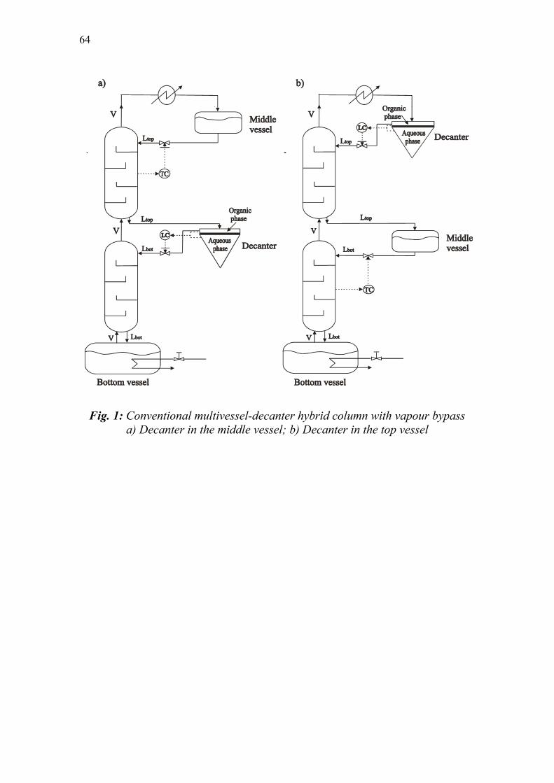
64
Fig. 1: Conventional multivessel-decanter hybrid column with vapour bypass a) Decanter in the middle vessel; b) Decanter in the top vessel

Chapter 4. Time requirements for heteroazeotropic distillation in batch columns 65
Fig. 2: Modified multivessel-decanter hybrid column with no vapour bypass. a) Decanter in the middle vessel; b) Decanter in the top vessel
All columns are operated as closed systems. There are no distillate or bottom streams taken out from the columns. The final products are accumulated in the vessels and discharged when the specifications are satisfied. In the multivessel column a ternary mixture can be separated simultaneously in one such closed operation. In the rectifier column the separation is sequential. The products are separated one at a time and for a ternary mixture a sequence of two such closed operations is needed. The separation sequence resembles the direct split in continuous columns. From the practical point of view, closed operation modes are preferable over traditional open operation modes, like constant reflux or constant distillate or optimal reflux ratio policies. The closed operation mode requires minimum operator intervention and monitoring, there is a definite distinction between the product changeovers and it is easier to assure the product qualities (Sorensen and Prenzler, 1997). Moreover, closed operation modes can also exhibit advantages in terms of separation time requirements. Sorensen and Skogestad (1994)

66
realized 30% time savings for difficult separations where a small amount of light product is to be recovered. The rectifier column was operated under the cyclic policy, which is characterised by repeating three periods: “filling up” of the reflux drum, “total reflux” (closed operation) of the column and finally “dumping” of the condenser holdup. Noda et al. (1999) have also shown that the closed rectifier, called “total reflux column”, performs equal or better than the rectifier or the stripper column operated under traditional open policies when the operation in all columns was optimized. This work addresses the separation of ternary heteroazeotropic mixtures in the three hybrid column configurations shown in Figs. 1-3. The objective is to recover all three original components with acceptable purity. The emphasis is on the batch time requirements in the different columns in order to find the best column candidate for such separations. The study is structured as follows. First, the mathematical model of the processes is presented and the simulation procedure is explained. Then, three examples are presented for heteroazeotropic systems classified under Serafimov’s classes 1.0-2, 1.0-1a and 2.0-2b. First, we explain how such mixtures can be separated in the hybrid columns and second, we provide, compare and discuss the batch time requirements in each column. The paper ends with some concluding remarks.
Fig. 3: Rectifier-decanter hybrid column with the decanter in the top vessel

Chapter 4. Time requirements for heteroazeotropic distillation in batch columns 67
2. Simulations
2.1 The model
The mathematical model of the processes used in our simulations consists of overall and component material balances; vapour-liquid and liquid-liquid equilibrium modelled by the NRTL activity coefficient model with binary parameters taken from the DECHEMA data series (Gmehling and Onken, 1977; DDBST Gmbh, 2002; Sorensen and Arlt, 1980), indirect level control in the vessels with P temperature controllers; direct level control in the decanter with a PI level controller and temperature estimations in the stages by a bubble point calculation under atmospheric pressure. The model is based on the following assumptions: Staged distillation column sections, constant molar vapour flows (molar boilup) in the column, constant molar liquid holdup on all stages and negligible vapour holdup, perfect mixing and equilibrium in all stages, ideal vapour phase, except in the second system studied (Serafimov’s class 1.0-1a) where association (dimerisation) of the vapour phase is considered for acetic acid. The thermodynamic data for the mixtures studied here are given in the Appendix. The resulting model takes the form of a set of differential and algebraic equations (DAE system) with a total of NT*(NC+1) state variables, where NT is the total number of stages in the column sections plus the vessels (3 for the multivessel configurations and 2 for the rectifier column) and NC is the number of components. The resulting DAE system is solved in Matlab with the DAE solver ODE15s.
2.2 Simulation details
Batch time comparisons are provided for three common classes of heteroazeotropic systems. We consider batch time, as a direct indication of energy consumption since the molar heat rate (molar boilup) in the reboiler is constant during the process. Using such a simple comparison criterion (time requirements), instead of a more general one, e.g. annual profit (Low and Sorensen, 2004) limits the findings of this study. Moreover, the formulation of a more advanced optimisation problem could highlight the effect of issues like, number of stages, control parameters, operating conditions, etc, in the objective function and could give a more spherical view of the advantages of each column configuration. Such detailed optimisation studies were provided by Furlonge et al. (1999) and Low and Sorensen (2004), and are beyond the scope of this study.

68
The simple criterion of minimum batch time is used here in order to compare the separation performance. The economic benefits of doing so are obvious. Reduced batch time makes the equipment available for other separation tasks and reduces the energy consumption if we assume that the molar heat rate in the column is constant. In order to minimize batch time, all columns are operated at maximum molar boilup (reboiler capacity). The vapour flow is constant in each column and equal in all three columns. The ratio of the vapour flow relative to the initial feed (V/F) is a measure of how many times the feed is boiled every hour. This is chosen to be close to unity (once per hour). Theoretically, the minimum batch time is achieved for infinite number of stages. In practice, in our simulations, each column section has sufficient number of trays for the given separation and therefore the time calculations are not depended on the number of stages. The same number of stages was used in both the conventional multivessel and the rectifier column for a fair comparison. Thus, the number of stages in the rectifier column is the sum of the stages in the two sections of the multivessel. The modified multivessel has one stage less than the conventional since the middle vessel is actually an additional equilibrium stage. Column and simulation data are given in Table A in the Appendix. The effect of the liquid column holdup in the separation times is not addressed in this study. All columns have constant very small liquid holdup negligible compared to the initial feed (total 2% of the charge). This means that the dynamics inside the column sections are negligible compared to that in the product vessels and all of the initial charge is recovered in the vessels at the end of the process. The initial distribution of the feed in the vessels of the multivessel column has an effect on the separation time and our simulation experience is that, in most cases, it is optimal or close to optimal to charge the feed in the reboiler. This statement holds, at least, for the systems and feed compositions studied here. In the multivessel column, 94% of the total charge is fed in the reboiler, 5% in the middle vessel and only 1% in the top vessel. In the rectifier column, 99% of the charge is fed in the reboiler and 1% in the top vessel. More detailed studies on this issue showed that the simple “feed in the reboiler” policy proved to be either optimal or close to optimal for the closed multivessel (Hasebe et al., 1999; Furlonge et al., 1999 and Low and Sorensen, 2002). Additionally, this feed policy resembles the one used in the rectifier where the feed is charged in the reboiler. A simple indirect level control in the vessels of the multivessel column based on temperature feedback control loops is employed (Skogestad et al., 1997). The feasibility of this control strategy was also verified experimentally for the

Chapter 4. Time requirements for heteroazeotropic distillation in batch columns 69
separation of a quaternary mixture (Wittgens and Skogestad, 2000). The same simple control approach is employed in the rectifier. This simple control strategy proved to be robust in anticipating uncertainties in the feed composition. The temperature measurements for the T-controllers are situated in the centre of the column section in both the multivessel and the rectifier column. The temperature setpoints are set to the average of the boiling point of the two pure components or azeotropes separated in this column section. In the decanters a direct level PI-controller is used instead of a temperature controller (Skouras and Skogestad, 2004b). Same controller setpoints and tuning parameters were used in all columns for fair comparison and are given in Table A2 in the Appendix. The batch time calculations do not include charging of the columns, preheating, product discharging and shutdown. These are considered to be the same for both the multivessel and the rectifier column. The only exception is the product discharging period, which is higher for the rectifier because of the time required to discharge the top vessel holdup between the two cycles (off-cut fractions). This is an additional advantage for the multivessel configurations.

70
3. Results
In this section we present three examples for the separation of ternary heterogeneous azeotropic mixtures in different column configurations. The first mixture is classified under Serafimov’s topological class 1.0-2, the second one is an example of class 1.0-1a and the last one is a system representing class 2.0-2b. The feasibility of separating these three classes of heteroazeotropic systems in a closed multivessel-decanter hybrid was presented by Skouras and Skogestad (2004b). The emphasis is now, not on how we actually perform the separation, even if it will be briefly illustrated, but on the time requirements for each separation.
3.1 Serafimov’s topological class 1.0-2
Suppose that a ternary mixture of methanol/water/1-butanol is to be separated by batch distillation into three pure products. Water and 1-butanol form a heterogeneous azeotrope and an immiscibility gap over a limited region of ternary compositions exists. The distillation line map of the mixture, modelled by NRTL, is shown on Fig. 4. The stable nodes are noted as (sn), unstable nodes as (un) and saddles as (s). A system with such a distillation line (or residue curve) map is classified under Serafimov’s topological class 1.0-2. A distillation boundary, running from methanol (unstable node) to the binary heteroazeotrope (saddle) divides the composition space in two regions, thus limiting the feasible products under distillation. The heteroazeotrope is a saddle, which means that it behaves as the intermediate “component” under distillation. Therefore, in the multivessel column the heteroazeotrope is accumulated in the middle vessel. The decanter is then placed in the middle vessel of the multivessel configuration as shown in Fig 1a and Fig. 2a. In the rectifier column there is no middle vessel and therefore the decanter is placed in the top vessel, as shown in Fig. 3. In the multivessel column the mixture is separated simultaneously in one closed operation with an initial build-up period. During this period the composition profile is established (Fig. 5a). The methanol is accumulated in the top and the butanol in the bottom vessel. The heteroazeotrope is accumulated in the middle vessel, thus, limiting the separation. A decanter in the middle vessel is then required to perform the liquid-liquid split and complete the separation task. This is the second step of the separation, called decanting period. During this step, the organic phase is refluxed back in the column and the aqueous phase is gradually accumulated in the middle vessel. Methanol stays in the top vessel and the butanol is accumulated in the bottom vessel. At the end of the process, all three original components are recovered in the vessels (Fig. 5b).

Chapter 4. Time requirements for heteroazeotropic distillation in batch columns 71
64.6 oC
Water [sn]100.0 oC
1-Butanol [sn]117.7 oC
het.az [s]93.0 oC
Serafimov,s class 1.0-2
____ distillation boundary
- - - - distillation lines
Methanol [un]
-.-.-.- binodal curve at 25oC
Fig. 4: Distillation line map of the mixture methanol/water/1-butanol

72
F
xB xM
bottom vesselmiddle vessel
-o-o- column liquid profile
........ composition evolution
Methanol [un]64.6 oC
Water [sn]100.0 oC
1-Butanol [sn]117.7 oC
het.az [s]93.0 oC
xT
top vessel
-.-.-.- binodal curve at 25oC
a)
64.6 oC
Water [sn]100.0 oC
1-Butanol [sn]117.7 oC
het.az [s]93.0 oC
-.-.-. binodal curve at 25oC
Methanol [un]
F
xT
xBxM0 xM
-o-o- column liquid profile
++++ composition evolution
middle vessel
b)
Fig. 5: Separation in the multivessel-decanter hybrid. a) Build-up period (Step 1); b) Decanting period (Step 2)

Chapter 4. Time requirements for heteroazeotropic distillation in batch columns 73
The separation in the modified configuration of the multivessel column, without the vapour bypass, is performed in the same way as in the conventional multivessel and it will not be described again. The separation in the closed rectifier column will be described more detailed. The products are separated one at a time in a sequence that resembles the direct split in continuous columns. The column has two vessels and thus, two closed operations, called cycles, are needed for the separation of a ternary system. An off-cut fraction is also needed between the cycles. For a mixture of class 1.0-2 the separation is performed in two cycles with a build-up period in between. Cycle 1 is a common rectification step in order to recover the light component (methanol) in the top vessel. Cycle 1 of the process is shown in Fig. 6a. The still (bottom vessel) is following a linear path away from the component (methanol) accumulated in the top vessel. Cycle 1 is terminated when the specification for methanol in the top vessel is fulfilled. Then, the vessel holdup is discharged instantaneously. A small amount of methanol still remains in the column and can contaminate the products of Cycle 2. An off-cut fraction is then removed during a closed operation operated for a short time with the same indirect level control and control parameters as for the second cycle. The off-cut fraction removed from the top vessel is equal to the total column’s holdup (0.1 kmol). Only two components are then left in the column, namely water and 1-butanol. A build-up period is needed in order to get some of the heteroazeotrope in the top vessel and afterwards Cycle 2 can start. Cycle 2 is a heteroazeotropic distillation step with a decanter placed in the top vessel. The two phases are decanted, the organic phase is refluxed back in the column and the aqueous phase is gradually accumulated in the decanter. Thus, during Cycle 2, the still is getting enriched in 1-butanol and the top vessel in water, as shown in Fig. 6b. For simplicity the off-cut fraction and the build-up period between the two cycles are not shown in Fig. 6. An equimolar feed xF is processed and the simulations were terminated when the composition specifications for the products in the vessels were fulfilled. Batch time requirements are provided for two specification sets: x1
spec=[0.99,0.97,0.99], x2
spec=[0.99,0.98,0.99]. The specification for the aqueous phase (xaq=0.98) in the second set is close to the maximum equilibrium value (xaq
max=0.981) determined by the binodal curve at 25ºC. This is the theoretically maximum concentration of water we can recover in the vessel in such a process and indicates the severity of the specification. The batch time comparisons are summarized in Table 1. The time requirements in the conventional multivessel-decanter hybrid are used as a basis for the comparisons. A positive sign (+) in Table 1 indicates longer process times compared to the conventional multivessel. A negative sign (-) indicates shorter process times (time savings).

74
xF
xT
xB
top vessel
still pathCYCLE 1
-o-o- column liquid profile
....... composition evolution
Methanol [un]64.6 oC
Water [sn]100.0 oC
1-Butanol [sn]117.7 oC
het.az [s]93.0 oC
-.-.-. binodal curve at 25oC
a)
Methanol [un]
64.6 oC
Water [sn]100.0 oC
1-Butanol [sn]117.7 oC
het.az [s]93.0 oC
xT
xB xF2 top vesselstill path
CYCLE 2
-o-o- column liquid profile
++++ composition evolution
-.-.-. binodal curve at 25oC
b)
Fig. 6: Separation in the rectifier-decanter hybrid in two cycles a) CYCLE 1: Recovering of methanol in the top vessel b) CYCLE 2: Recovering of water in the decanter and 1-butanol in the reboiler

Chapter 4. Time requirements for heteroazeotropic distillation in batch columns 75
Table 1: Time requirements and time savings (basis: conventional multivessel)
Specification
Conventional multivessel-
decanter hybrid
[h]
Modified multivessel-decanter
hybrid
[%]
Rectifier-decanter hybrid
[%]
[0.99,0.97,0.99]
3.4 -35 +29 Class 1.0-2
xF=[1/3,1/3,1/3] [0.99,0.98,0.99]
4.9 -33 +41
[0.97,0.97,0.99]
2.8 -7 +39 Class 1.0-1a
xF=[0.6,0.2,0.2] [0.98,0.99,0.99]
3.7 -11 +32
[0.97,0.97,0.99]
3.3 0 +61
Class 2.0-2b
xF=[0.45,0.05,0.5]
[0.999,0.999,0.999]
4.3 0 +88
Conventional multivessel vs. rectifier column
The results in Table 1 show that the conventional multivessel-decanter hybrid is faster than the rectifier-decanter hybrid. The rectifier requires from 29% to 41% more time depending on the specification set. The time advantages of the multivessel become more pronounced (from 29% to 41%) as the specification for the component recovered in the middle vessel (aqueous phase) becomes stricter. This is the opposite of what was observed by Meski et al., 1998 and also Skouras and Skogestad, 2004a for zeotropic systems, where the multivessel column was becoming less advantageous as the specification in the middle vessel was becoming tighter. This is explained by the different placement of the decanter in the two columns. In the multivessel column, the decanter is placed in the middle vessel and the components are separated simultaneously. This means that the decantation step in the middle vessel is performed in the presence of only small amounts of the light component, which mostly concentrates in the top stages of the column. In contrast, the separation in the rectifier column is done sequentially. First, the

76
methanol is recovered during cycle 1, and then cycle 2 is a heteroazeotropic distillation step with a decanter in the top of the column. This sequential operation requires cycle 1 to be run for long time in order to avoid excess amount of methanol entering the decanter during cycle 2. Recall that the specification for the aqueous phase accumulated in the decanter in the second set (0.98) is very tight. Even small amounts of methanol left in the column before starting cycle 2 make this specification infeasible. Cycle 1 has to be run for longer time than justified by the specification for methanol (0.99) and the column becomes proportionally less attractive for the second specification set. Thus, for heteroazeotropic systems of class 1.0-2, where the heteroazeotrope is a saddle, the multivessel is preferable over the rectifier even for strict specifications for the middle vessel product.
Conventional multivessel vs. modified multivessel
By comparing the results in Table 1 for the two modifications of the multivessel column we see that the elimination of the vapour bypass leads to additional time savings of 33% to 35%. This result verifies the superiority of the modified multivessel without the vapour bypass reported earlier in the literature (Skouras and Skogestad, 2004a). Moreover, we notice that the time savings in the modified multivessel are not strongly dependent on the specification set. However, we should note at this point that a modified multivessel with a vapour stream entering the decanter (middle) vessel, as shown in Fig. 1a and Fig. 2a, is not very wise from the practical point of view and is mostly of theoretical interest. Moreover, the decanter in our configurations is operated in 25ºC, which is significantly lower than that of the rest of the column. It is again impractical to have a hot vapour stream entering the decanter. An alternative could be to operate the decanter at boiling temperature, even if the binodal curve would become smaller. For batch operations this would not be a big problem because the additional amount of the organic phase, formed after cooling down the decanter (after operation), could be recycled to the next batch. Nevertheless, it is doubtful if someone would like to have a decanter with a vapour flow entering into it. Thus, we believe that for heteroazeotropic systems of class 1.0-2, the conventional multivessel of Fig. 1a is the most realistic alternative of all three columns.
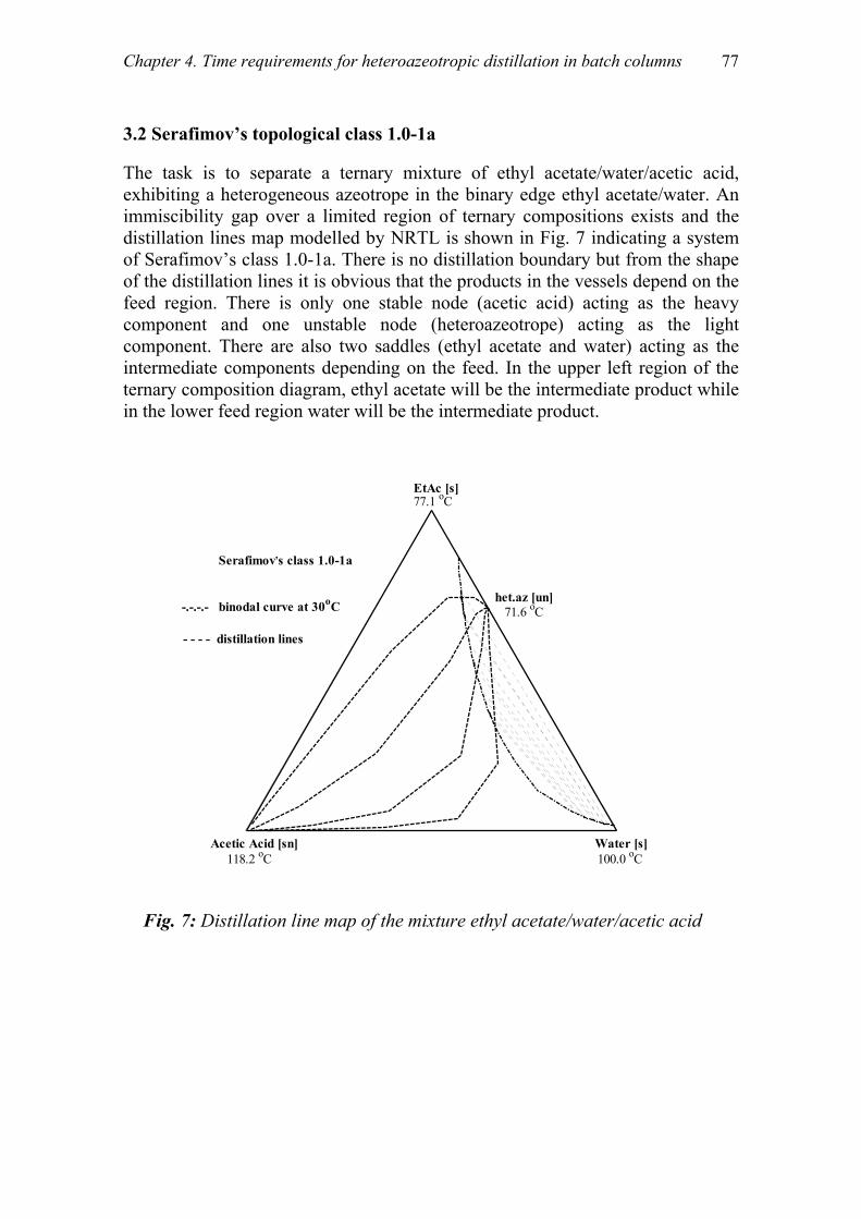
Chapter 4. Time requirements for heteroazeotropic distillation in batch columns 77
3.2 Serafimov’s topological class 1.0-1a
The task is to separate a ternary mixture of ethyl acetate/water/acetic acid, exhibiting a heterogeneous azeotrope in the binary edge ethyl acetate/water. An immiscibility gap over a limited region of ternary compositions exists and the distillation lines map modelled by NRTL is shown in Fig. 7 indicating a system of Serafimov’s class 1.0-1a. There is no distillation boundary but from the shape of the distillation lines it is obvious that the products in the vessels depend on the feed region. There is only one stable node (acetic acid) acting as the heavy component and one unstable node (heteroazeotrope) acting as the light component. There are also two saddles (ethyl acetate and water) acting as the intermediate components depending on the feed. In the upper left region of the ternary composition diagram, ethyl acetate will be the intermediate product while in the lower feed region water will be the intermediate product.
-.-.-.- binodal curve at 30oC
EtAc [s]77.1 oC
Water [s]100.0 oC
Acetic Acid [sn]118.2 oC
het.az [un]71.6 oC
Serafimov,s class 1.0-1a
- - - - distillation lines
Fig. 7: Distillation line map of the mixture ethyl acetate/water/acetic acid

78
We place the feed in the upper region of Fig. 7 where ethyl acetate is a saddle. The heteroazeotrope is the unstable node and it will boil overhead in the column. Thus, the decanter has to be placed at the top of the column, as shown in Fig. 1b and 2b. In the multivessel column, the separation is performed simultaneously in one closed operation with an initial build-up period. The purpose of this initial period is to get some of the heteroazeotrope in the decanter (top) vessel, as shown in Figure 8a. The second separation step (decanting period), where the heteroazeotrope is decanted and the organic phase is refluxed back in the column, can then start. The aqueous phase is gradually accumulated in the top vessel, the ethyl acetate in the middle vessel and the acetic acid in the bottom. At the end of the process, all three original components are recovered in the vessels, as shown in Fig. 8b. The separation is performed in the same way in the modified multivessel column without the vapour bypass. In the rectifier column the separation is again performed sequentially in two cycles with a build-up period before Cycle 1 and an off-cut fraction between the two cycles. Since for this azeotropic class (Class 1.0-1a) the heteroazeotrope is an unstable node, Cycle 1 will be a heteroazeotropic distillation step. A build-up period is needed and the heteroazeotrope is accumulated in the decanter before cycle 1 starts. During cycle 1, the heteroazeotrope is decanted and the organic phase is refluxed back in the column. The aqueous phase is then gradually accumulated in the top vessel, as illustrated in Fig. 9. Most of the water is removed during cycle 1 and the still (bottom vessel) consists almost of only ethyl acetate and acetic acid. A small off-cut fraction is needed after cycle 1 in order to remove the remaining water. Cycle 2 is then an almost binary rectification of ethyl acetate (top product) and acetic acid (bottom product), as shown in Fig. 9. In our simulations an initial feed xF=[0.6,0.2,0.2] is processed and the process was terminated when the specifications for the products in the vessels were fulfilled. Two specification sets were considered also in this case: x1
spec=[0.97,0.97,0.99] and x2
spec=[0.98,0.99,0.99]. The specification in the second set is stricter both for the aqueous phase in the top vessel and for the product (ethyl acetate) recovered in the middle vessel. Moreover, the specification (xaq=0.98) for the aqueous phase is close to the maximum equilibrium value (xaq
max=0.984) determined by the binodal curve at 30ºC. The batch time requirements for the process and the comparisons for different column configurations are given in Table 1.

Chapter 4. Time requirements for heteroazeotropic distillation in batch columns 79
-.-.-.- binodal curve at 30oC
EtAc [s]77.1 oC
Water [s]100.0 oC
Acetic Acid [sn]118.2 oC
het.az [un]71.6 oC
F
xTmiddlevessel top
vessel
-o-o- column liquid profile
....... composition evolution
a)
xM
xB
EtAc [s]77.1 oC
Water [s]100.0 oC
Acetic Acid [sn]118.2 oC
het.az [un]71.6 oC
F
xM
xB
xT0
xT
-o-o- column liquid profile
+++ composition evolution
topvessel
-.-.-.- binodal curve at 30oC
xM0
xB0
Fig. 8: Separation in the multivessel-decanter hybrid a) Build-up period (Step 1); b) Decanting period (Step 2)

80
EtAc [s]77.1 oC
Water [s]100.0 oC
Acetic Acid [sn]118.2 oC
het.az [un]71.6 oC
F
xBxT0
still path
topvessel
CYCLE 1
-o-o- column liquid profile
+++ composition evolution
-.-.-.- binodal curve at 30oC
a)
xT
EtAc [s]77.1 oC
Water [s]100.0 oC
Acetic Acid [sn]118.2 oC
het.az [un]71.6 oC
xB
xT
xF2
still path
top vessel
-o-o- column liquid profile
........ composition evolution
CYCLE 2
-.-.-.- binodal curve at 30oC
b)
Fig. 9: Separation in the rectifier-decanter hybrid in two cycles a) CYCLE 1: Recovering of water in the decanter b) CYCLE 2: Recovering of ethyl acetate in the decanter and acetic acid in the reboiler

Chapter 4. Time requirements for heteroazeotropic distillation in batch columns 81
Conventional multivessel vs. rectifier column
The results in Table 1 show that, also for class 1.0-1a, the rectifier column requires more time than the conventional multivessel in order to perform a given separation. The rectifier column requires 39% more time for the first specification set and 32% for the second tighter set, which indicates a weak dependence on the specification set. Intuitively, we would expect that the time advantages of the multivessel column would be much more reduced when the specification in the middle vessel is becoming tighter from 0.97 to 0.99. This intuition is based on the slow dynamics in the middle vessel of a conventional multivessel pointed out by Skouras and Skogestad (2004a) for zeotropic systems. However, the results are not verifying our intuition and the reason is the presence of the decanter in the top vessel. In such distillation-decanter hybrids, the dynamics in the decanter play an important role, as important as the dynamics in the other vessels. The specification in the second step is stricter in both the decanter (from 0.97 to 0.98) and in the middle vessel (from 0.97 to 0.99). The “middle vessel effect” (slow dynamics in the middle vessel) in favour of the rectifier column, is overweighed by the “decanter effect” (slow dynamics in the decanter) in favour of the multivessel column. Thus, the multivessel column is again preferable over the rectifier column even for high specifications in the middle vessel, for this class of heteroazeotropic systems.
Conventional multivessel vs. modified multivessel
When we compare the conventional multivessel with the modified multivessel, a rather surprising result is observed since the former does not exhibit any significant advantage over the latter. The time savings in the modified multivessel are significantly reduced to 7-11% compared to 33%-35% in the first example. The decisive factor here is again the dynamics in the decanter in the top of the column. Recall that the only difference between the two multivessel configurations is the vapour stream from the stripping section to the rectifying section, which can bypass or not the middle vessel. In the latter case the dynamics in the middle vessel are significantly improved and the separation task is accomplished faster in the modified multivessel column. However, in the multivessel-decanter hybrids the dynamics of the decanter are also a decisive factor. Thus, improving the dynamics of the middle vessel by avoiding the vapour bypass is not that important anymore. The “decanter effect” (slow decanter dynamics) outweighs the “middle vessel effect” (fast middle vessel dynamics) and the modified multivessel is only marginally better than the conventional one.

82
We note here that we can improve the dynamics in the decanter vessel by employing more “aggressive” level control. In practice this would mean to increase the flow of the organic phase refluxed back in the column so as the accumulation of the aqueous phase would become faster and the specification would be reached in shorter time. However, such an increase in the reflux rate would not be without drawbacks. By looking at the shape of the binodal curve in Fig. 7 we see that the organic phase still contains a large amount of water (around 15% at 25ºC). A more aggressive reflux policy would force a large amount of water re-entering the rectifying section and consequently entering also the middle vessel. There is obviously a trade-off between the time we save by sending faster the organic phase back in the column and the time we lose by the redistribution effect (re-mixing water and ethyl acetate) in the middle vessel. In conclusion, the conventional multivessel-decanter hybrid is proposed for class 1.0-1a since we experience only marginal time savings by eliminating the vapour bypass.

Chapter 4. Time requirements for heteroazeotropic distillation in batch columns 83
3.3 Serafimov’s topological class 2.0-2b
The last ternary mixture studied is an example of topological class 2.0-2b and is the mixture benzene/water/1,4-dioxane. The distillation line map of the mixture is shown in Fig. 10. The heteroazeotrope is the unstable node, dioxane is the stable node while the homoazeotrope and benzene are the two saddles of the distillation line map. There is one distillation boundary running from the heteroazeotrope to the homoazeotrope, thus dividing the composition space in two distillation regions. An initial feed xF=[0.45,0.05,0.50] as shown in Fig. 10 is to be processed in batch columns. The heteroazeotrope is the unstable node and thus, the decanter has to be placed at the top of the multivessel column, as shown in Fig. 1b and Fig. 2b. The separation process for class 2.0-2b resembles the process for class 1.0-1a and therefore it would be briefly described but not illustrated with figures.
Benzene [s]80.1 oC
Water [sn]100.0 oC
1,4-Dioxane [sn]101.3 oC
het.az [un]69.0 oC
hom.az [s]86.6 oC
____ distillation boundary
- - - - distillation linesxF
*
Serafimov,s class 2.0-2b
-.-.-.- binodal curve at 25 oC
Fig. 10: Distillation line map of the mixture benzene/water/1,4-dioxane

84
In the multivessel column the mixture is separated simultaneously in one closed separation with an initial build-up period in order to get some of the heteroazeotrope in the decanter (top) vessel. The decanting period can then start. The heteroazeotrope is decanted, the organic phase is refluxed back in the column and the aqueous phase is gradually accumulated in the top vessel. At the end of the process, all three original components are recovered in the vessels. The separation is performed similarly in the modified multivessel without the vapour bypass. Two cycles are required for the separation in the rectifier column. In addition, a build-up period before cycle 1 and an off-cut fraction between the two cycles is required. The purpose of the build-up period is to obtain some of the heteroazeotrope in the top vessel. During Cycle 1 the heteroazeotrope is decanted and the organic phase is refluxed back in the column. The aqueous phase is then gradually accumulated in the decanter. An off-cut fraction is removed after cycle 1 and the excess water is removed from the column. Cycle 2 is an almost binary distillation between benzene and dioxane with the first one recovered at the top vessel and the heavy dioxane recovered from the still. The simulations were stopped when the composition specifications for the products in the vessels were fulfilled. Two specification sets were studied: x1
spec=[0.97, 0.97, 0.99], x2spec=[0.999, 0.999, 0.999]. The second specification
set is very tight in all the vessels. The miscibility of benzene and water is negligible and therefore the aqueous phase is almost pure water and the specification for the aqueous phase can be set as high as 99.9%. The batch time comparisons for the process are given in Table 1.
Conventional multivessel vs. rectifier column
The results for class 2.0-2b in Table 1 verify once again that the rectifier column is more time consuming than the multivessel column. The rectifier requires 61%-88% more time and, moreover, it becomes relatively less attractive as the specifications in the vessels become stricter. This case study represents the ultimate example in favour of the multivessel column. The reason is the large amount of the heavy component in the initial feed (50% dioxane in the feed). The heavy component will be accumulated at the bottom vessel and, thus, the whole process is governed by the dynamics in this vessel. The same was observed by Skouras and Skogestad (2004a) for a zeotropic system with a feed rich in the heavy component. Thus, the multivessel column is highly recommended over the rectifier column in this case.

Chapter 4. Time requirements for heteroazeotropic distillation in batch columns 85
Conventional multivessel vs. modified multivessel
In the previous case of class 1.0-1a we show that the elimination of the vapour bypass was not so important in the case of distillation-decanter hybrids where the decanter is placed in the top of the column. The decisive factor was the dynamics of the decanter that play an important role and lessens the improved middle vessel dynamics of the modified multivessel. The results are even more pronounced in this case, where we observe no difference in the time requirements between the two multivessel configurations. In this case it is the bottom vessel that governs the dynamics of the process and outweighs completely the faster middle vessel dynamics. Thus, improving the dynamics of the middle vessel by eliminating the vapour bypass is not important.

86
4. Conclusions
We presented batch time requirements for the separation of ternary heterogeneous azeotropic mixtures in closed batch distillation-decanter hybrids. Three systems were studied, each one representing a different topological class in Serafimov’s classification, namely classes 1.0-2, 1.0-1a and 2.0-2b. All separations were performed in closed hybrid processes were distillation is combined with decantation in order to enhance the separation task. The column arrangements under consideration were a conventional multivessel column with the vapour stream bypassing the middle vessel, a modified multivessel with the vapour stream entering the middle vessel and a rectifier column. The decanter was placed either in the top or in the middle vessel of the multivessel configurations depending on the nature (class) of the system separated. The results, for all three cases presented, verified that multivessel configurations perform always better than the rectifier column, in terms of batch separation times. This result, which is well justified in the related literature for zeotropic systems, shown also to be valid for the heteroazeotropic mixtures studied here. The elimination of the vapour bypass in the modified multivessel column, proposed in the literature for enhancing the dynamics of the conventional multivessel, is not justified by the results for the hybrid version of the column with the decanter. Moreover, practical issues make the idea of eliminating the vapour bypass in heteroazeotropic distillation rather unattractive. Thus, the conventional multivessel-decanter hybrid is recommended for the separation of heteroazeotropic mixtures.

Chapter 4. Time requirements for heteroazeotropic distillation in batch columns 87
5. Notation
F Feed [kmol] Ltop Liquid flows in the rectifying section of the
multivessel column [kmol h-1]
Lbot Liquid flows in the stripping section of the multivessel column
[kmol h-1]
LC Level controller N Number of stages in the rectifier column NC Number of components (3 in all examples) Nr Number of stages in the rectifying section of
the multivessel column
Ns Number of stages in the stripping section of the multivessel column
NT Total number of stages in the columns + number of product vessels
(s) Saddle (sn) Stable node TC Temperature controller (un) Unstable node V Vapour flows (molar boilup) in the columns [kmol h-1] V/F Ratio of the molar boilup over the initial feed [h-1] xB Composition in the bottom vessel xF Feed composition xF2 Still composition at the beginning of Cycle 2
in the rectifier column
xM Composition in the middle vessel xM0 Composition in the middle vessel at the
beginning of the decanting period
xT Composition in the top vessel xT0 Composition in the top vessel at the
beginning of the decanting period

88
APPENDIX
Table A1: Column data for the simulations
Conventional multivessel-
decanter hybrid
Modified multivessel-
decanter hybrid
Rectifier-decanter hybrid
Stages per section Nr = 25, Ns = 25 Nr = 25, Ns = 24 N = 50 Initial feed MF = 5.385 kmol MF = 5.385 kmol MF = 5.385 kmol Initial condenser holdup MT0 = 0.035 kmol MT0 = 0.035 kmol MT0 = 0.035 kmol Initial middle vessel holdup MF0 = 0.250 kmol MF0 = 0.250 kmol No middle vessel Initial reboiler holdup MB0 = 5.000 kmol MB0 = 5.000 kmol MB0 = 5.250 Kmol Trays holdup Mi = 1/500 kmol Mi = 1/500 kmol Mi = 1/500 kmol Vapour flow V = 5 kmol h-1 V = 5 kmol h-1 V = 5 kmol h-1
Table A2: Controller data
Serafimov’s topological class 1.0-2 (methanol/water/1-butanol) Build-up period (Step 1): Two P temperature controllers Kc,r = 0.176 kmol h-1 ºC-1 Tsp,r = 78.80 ºC Kc,s = 0.202 kmol h-1 ºC-1 Tsp,s = 105.35 ºC Decanting period (Step 2): A P temperature controller and a PI level controller Kc,r = 0.176 kmol h-1 ºC-1 Tsp,r = 78.80 ºC Kc,s = 10 h-1 τI = 0.5 h Msp,s =0.001 kmol Cycle 1: One P temperature controller Kc = 0.176 kmol h-1 ºC-1 Tsp = 78.80 ºC Cycle 2: One PI level controller Kc = 10 h-1 τI = 0.5 h Msp =0.001 kmol
Serafimov’s topological class1.0-1a (ethyl acetate/water/acetic acid)
Build-up period (Step 1): Two P temperature controllers Kc,r = 0.909 kmol h-1 ºC-1 Tsp,r = 74.35 ºC Kc,s = 0.122 kmol h-1 ºC-1 Tsp,s = 97.65 ºC Decanting period (Step 2): A PI level controller and a P temperature controller Kc,r = 10 h-1 τI = 0.5 h Msp,s =0.001 kmol Kc,s = 0.122 kmol h-1 ºC-1 Tsp,s = 97.65 ºC Cycle 1: One PI level controller Kc= 10 h-1 τI = 0.5 h Msp =0.001 kmol Cycle 2: One P temperature controller Kc = 0.122 kmol h-1 ºC-1 Tsp = 97.65 ºC
Serafimov’s topological class 2.0-2b (benzene/water/1,4-dioxane)
Build-up period (Step 1): Two P temperature controllers Kc,r = 0.451 kmol h-1 ºC-1 Tsp,r = 74.55 ºC Kc,s = 0.236 kmol h-1 ºC-1 Tsp,s = 90.7 ºC Decanting period (Step 2): A PI level controller and a P temperature controller Kc,r = 10 h-1 τI = 0.5 h Msp,s =0.0001 kmol Kc,s = 0.236 kmol h-1 ºC-1 Tsp,s = 90.7 ºC Cycle 1: One PI level controller Kc= 10 h-1 τI = 0.5 h Msp =0.001 kmol Cycle 2: One P temperature controller Kc = 0.236 kmol h-1 ºC-1 Tsp = 90.7 ºC

Chapter 4. Time requirements for heteroazeotropic distillation in batch columns 89
Table A3: Thermodynamic data for the mixtures studied (Gmehling and Onken, 1977; DDBST Gmbh, 2002 and Sorensen and Arlt, 1980)
Class 1.0-2: methanol (1) / water (2) / 1-butanol (3) VLE Aij (cal/mol) Aji (cal/mol) aij=aji 1-2 -48.6725 610.4032 0.3001 1-3 746.0477 -529.6674 0.3038 2-3 2794.6704 570.1362 0.4700
Binodal (25ºC) Aij (K) Aji (K) aij=aji 1-2 45.740 -147.43 0.2 1-3 -178.09 703.82 0.2 2-3 1756.8 -344.40 0.2
Antoine A B C 1 8.08097 1582.271 239.726 2 8.07131 1730.630 233.426 3 7.92484 1617.520 203.296
Class 1.0-1a: ethyl acetate (1) / water (2) / acetic acid (3)
VLE Aij (cal/mol) Aji (cal/mol) aij=aji 1-2 935.6880 2316.3631 0.4104 1-3 844.2996 -436.9443 0.3138 2-3 712.1791 320.1059 1.4032
Binodal (25ºC) Aij (K) Aji (K) aij=aji 1-2 163.41 1159.1 0.2 1-3 685.59 -647.88 0.2 2-3 -249.0 198.55 0.2
Antoine A B C 1 7.10179 1244.950 217.881 2 8.07131 1730.630 233.426 3 8.02100 1936.010 258.451
Dimerisation Constant A B
3 -10.421 3166
Class 2.0-2b: benzene (1) / water (2) / 1,4-dioxane (3) VLE Aij (cal/mol) Aji (cal/mol) aij=aji 1-2 1522.2402 1821.8322 0.3547 1-3 -293.8487 434.1172 0.3022 2-3 1551.5163 1097.8251 0.5457
Binodal (25ºC) Aij (K) Aji (K) aij=aji 1-2 1411.4 1320.6 0.2 1-3 129.49 11.834 0.2 2-3 525.41 49.551 0.2
Antoine A B C 1 6.87987 1196.760 219.161 2 8.07131 1730.630 233.426 3 7.43155 1554.679 240.337

90
6. References
DDBST Gmbh, (2002), Dortmund data bank software package (Educational Version: Release 2002), www.ddbst.de Duessel, R., Stichlmair, J., (1995), Separation of azeotropic mixtures by batch distillation using an entrainer, Computers and Chemical Engineering, S19, S113. Furlonge, H.I., Pantelides, C.C., Sorensen, E., (1999), Optimal operation of multivessel batch distillation columns, AIChE J, 45 (4), 781. Gmehling, J., Onken, J., (1977), Vapour-liquid equilibrium data collection, DECHEMA Chemistry Data Series, Frankfurt am Main. Hasebe S., Abdul Aziz, B., Hashimoto, I., Watanabe, T., (1992), Optimal design and operation of complex batch distillation column, Proceedings IFAC Workshop on Interactions between Process Design and Process Control, Pergamon Press: Oxford, U.K., 177. Hasebe, S., Noda, M., Hashimoto, I., (1997), Optimal operation policy for multi-effect batch distillation system, Computers and Chemical Engineering (Suppl.), 21S, S1221. Hasebe, S., Noda, M., Hashimoto, I., (1999), Optimal operation policy for total reflux and multi-effect batch distillation systems, Computers and Chemical Engineering, 23, 523. Hilmen, E.K., Kiva, V.N., Skogestad, S., (2002), Topology of ternary VLE diagrams: elementary cells, AIChE J., 48 (4), 752. Kiva, V.N., Hilmen, E.K., Skogestad, S., (2003), Azeotropic phase equilibrium diagrams: a survey, Chemical Engineering Science, 58, 1903. Koehler, J., Haverkamp, H., Schadler, N., (1995), Zur diskontinuierlichen Rektifikation azeotroper Gemische mit Hilfsstoffeinsatz, Chem.-Ing.-Tech, 67 (8), 967. Low, K.H., Sorensen, E., (2002), Optimal operation of extractive distillation in different batch configurations, AIChE J., 48 (5), 1034. Low, K.H., Sorensen, E., (2003), Simultaneous optimal design and operation of multivessel batch distillation, AIChE J., 49 (10), 2564.

Chapter 4. Time requirements for heteroazeotropic distillation in batch columns 91
Low, K.H., Sorensen, E., (2004), Simultaneous optimal design and operation of multipurpose batch distillation columns, Chemical Engineering and Processing (Special Issue: Distillation & Absorption), 43 (3), 273. Meski, G.A., Han, M., Bekiaris, N., Morari, M., (1998), Optimality for batch distillation configurations, IFAC Symposium DYCOPS-5, Corfu, Greece, 387. Noda, M., Kato, A., Hasebe, S., Hashimoto, I., (1999), Optimal structure of batch distillation column, Computers and Chemical Engineering (Suppl.), S23, S105. Robinson C.S., Gilliland, E.R., (1950), Elements of fractional distillation, Vol. 4, McGraw Hill, New York. Rodriguez-Donis, I., Gerbaud, V., Joulia, X., (2001a), Heterogeneous entrainer selection for the separation of azeotropic and close boiling temperature mixtures by heterogeneous batch distillation, Ind. Eng. Res., 40, 4935. Rodriguez-Donis, I., Pardillo-Fontdevila, E., Gerbaud, V., Joulia, X., (2001b), Synthesis, experiments and simulation of heterogeneous batch distillation processes, Computers and Chemical Engineering, 25, 799. Rodriguez-Donis, I., Gerbaud, V., Joulia, X., (2002), Feasibility of heterogeneous batch distillation processes, AIChE J., 48 (6), 1168. Skogestad, S., Wittgens, B., Litto, R., Sorensen, E., (1997), Multivessel batch distillation, AIChE J, 43 (4), 971. Skouras, S., Skogestad, S., (2004a), Time (energy) requirements in closed batch distillation arrangements, Computers and Chemical Engineering, 28 (5), (2004), 829. Skouras, S., Skogestad, S., (2004b), Separation of ternary heteroazeotropic mixtures in a closed multivessel batch distillation-decanter hybrid, Chemical Engineering and Processing (Special Issue: Distillation & Absorption), 43 (3), 291. Sorensen, J.M., Arlt, W., (1980), Liquid-liquid equilibrium data collection, DECHEMA Chemistry Data Series, Frankfurt am Main. Sorensen, E., Prenzler, M., (1997), A cyclic operating policy for batch distillation-theory and practice, Computers and Chemical Engineering (Suppl.), S21, S1215.

92
Sorensen, E., Skogestad, S., (1994), Optimal operating policies of batch distillation with emphasis on the cyclic operating policy, PSE ’94, 5th International Symposium on Process Systems Engineering, 449. Stichlmair, J.G., Fair, J.R., (1998), Distillation: principles and practice, Wiley-VCH. Warter, M., Stichlmair, J., (1999), Batchwise extractive distillation in a column with a middle vessel, Computers and Chemical Engineering (Suppl.), S23, S915. Wittgens, B., Skogestad, S., (2000), Closed Operation of multivessel batch distillation: experimental verification, AIChE J., 46, (6), 1209.

Chapter 5
HETEROAZEOTROPIC BATCH DISTILLATION
Process analysis and simulation results
S. Skouras1, V. Kiva2, S. Skogestad1
1 Norwegian University of Science & Technology, Department of Chemical Engineering, Sem Saelandsvei 4, 7491, Trondheim, Norway
2 Karpov Institute of Physical Chemistry, Laboratory of Mixture Separation,
103604, Moscow, Russia
This paper was sent for publication in April 2004 to
AIChE Journal
Abstract
The separation of close-boiling and azeotropic mixtures by heterogeneous azeotropic distillation is addressed in batch columns. Both a common rectifier and a multivessel batch column are considered. A theoretical and graphical analysis of the process is presented for both column configurations and different separation strategies are presented. A simple control scheme is proposed for the practical operation of the columns, the implementation of different strategies and the realisation of the steady state results. Dynamic simulations for mixtures classified under Serafimov’s topological classes 2.0-2b and 3.1-2 verify the theoretical findings. The results show that heteroazeotropic batch distillation exhibits large flexibility. The column profile can be totally restored during the process and lie in regions different than those of the initial feed. The still path can cross distillation boundaries and the still product does not have to be the stable node of the feed region. Such results cannot be obtained by homogeneous azeotropic batch distillation.

94
1. Introduction
The separation of azeotropic and close-boiling mixtures is often faced in the organic chemical industry. Batch distillation is by far the most common unit operation in the pharmaceutical and fine/specialty chemical industry because of small-scale production of high added-value products and frequent changes of the separation task. Consequently, establishing new and efficient methods for batch distillation of such mixtures is an important issue both for the academia and the industry. Separation of azeotropic (or close-boiling) mixtures is impossible (or uneconomical) by common distillation and therefore special techniques have to be applied. If pressure swing distillation is not efficient because of insensitivity of the original mixture to pressure changes then another component, called entrainer, has to be added to facilitate separation and enhance distillation. When a heavy entrainer is added continuously in the top section of the batch column the process is called extractive batch distillation. When an entrainer is added batchwise to the original mixture we simply call it azeotropic batch distillation. If the entrainer is miscible with the components of the original mixture the process is called homogeneous azeotropic (homoazeotropic) batch distillation. The entrainer can form one or more azeotropes with the original components. When the entrainer is immiscible and forms heterogeneous azeotrope with at least one (and preferably with only one) of the original components, the process is called heterogeneous azeotropic (heteroazeotropic) batch distillation. This study is about heteroazeotropic batch distillation; thus, we study entrainers added batchwise to the original mixture and leading to the formation of heteroazeotrope(s). The column configuration used for the separation task is another important issue. The most common batch column is the so-called batch rectifier or regular column where the feed is charged to the reboiler and the products are taken from the top of the column during a rectification process (Diwekar, 1995). Alternatively, an inverted column also called the batch stripper can be employed (Sorensen and Skogestad, 1996). The feed is charged in the reflux drum at the column top and the products are withdrawn from the bottom during a stripping process. Much attention has been given lately to a special batch configuration called the multivessel column or middle vessel column (Robinson and Gilliland, 1950). The multivessel column can be realised as a combination of a rectifier and a stripper (Hasebe et al., 1992 and Skogestad et al., 1997). It has both a rectifying and a stripping section and it is possible to obtain a light and a heavy fraction simultaneously from the top and the bottom of the column. An intermediate fraction may also be recovered in the middle vessel. Rectifier and multivessel configurations are studied here but batch strippers are not considered.

Chapter 5. Heteroazeotropic batch distillation: Process analysis and simulation results
95
In contrast to its heterogeneous counterpart, homogeneous azeotropic batch distillation has achieved much attention in the literature. Bernot et al. (1990, 1991), Duessel and Stichlmair (1995), Stichlmair and Fair (1998) and Rodriguez et al. (2001a) have addressed homoazeotropic distillation in batch rectifiers and strippers, while Cheong and Barton (1999a-c) and Warter and Stichlmair (2000) have studied the process in multivessel configurations. Somewhat surprisingly, taken into account its industrial importance, the literature on heteroazeotropic batch distillation is still limited and somewhat controversial. Duessel and Stichlmair (1995) showed simulation results for the heteroazeotropic rectification of the mixture pyridine/water using toluene as entrainer. Synthesis methods from homoazeotropic batch distillation were used. The system was revisited by Rodriguez et al. (2001b, 2002) who criticised the analysis from Duessel and Stichlmair (1995) and pointed out that synthesis methods for homogeneous mixtures cannot be extended to heterogeneous ones without care. Koehler et al. (1995) showed experimental results for the separation of an azeotropic mixture of water and a high-boiling component using a light heterogeneous entrainer, but did not specify the actual components used. They showed that the process behaves different from homoazeotropic batch distillation and that the still path could cross the distillation boundary. They also proposed different separation strategies and compared them in terms of time requirements. Stichlmair and Fair (1998) presented results for the separation of ethanol/water using toluene as a heterogeneous entrainer. The proposed separation scheme was inspired from the corresponding scheme for continuous columns described by Stichlmair and Herguijuela (1992) and required one stripper and one rectifier-decanter hybrid. Thus, not all possibilities of the batch process were investigated. The presented results for the last mixture in our work, classified under Serafimov’s class 3.1-2, will show that the separation can be performed in a single rectifier-decanter hybrid if we take full advantage of the batch process. In a series of papers Rodriguez et al. (2001a,b,c and 2002) approached the heteroazeotropic batch distillation process both theoretically and experimentally. First, they provided entrainer selection rules and simulation results for heterogeneous mixtures and showed that heterogeneous entrainers offer more possibilities for the separation of azeotropic mixtures than homogeneous ones (Rodriguez et al., 2001a,b). Later, they verified their simulation results with experiments in a batch rectifier (Rodriguez et al., 2001c). In their last paper (Rodriguez et al., 2002) they attempted a more systematic theoretical analysis and developed synthesis methods for the process.

96
Skouras and Skogestad (2004a) showed simulation results for heteroazeotropic batch distillation in a closed multivessel column and developed feasibility rules for the process. Unfortunately, their feasibility analysis is partially incorrect since synthesis methods from homoazeotropic distillation were used and not all possibilities of the process were investigated. Skouras and Skogestad (2004b) provided also batch time comparisons for heteroazeotropic batch distillation of ternary mixtures in the closed rectifier and multivessel column and concluded that the multivessel column performs always better than the rectifier for such separations. The reason for the different results and conclusions on heteroazeotropic batch distillation is that different authors consider different operation modes of the process. If heteroazeotropic distillation is defined as a process where an original mixture is separated in the presence of a heteroazeotropic entrainer and not limited by some additional conditions, there are, generally, two modes to carry out the process. Mode I: The mixture is separated by distillation to recover all the heteroazeotrope in the decanter (closed operation with no liquid-liquid split), which then, after the distillation, is split into its two immiscible phases, namely the entrainer-lean and the entrainer-rich phase. Thus, Mode I may be viewed as a hybrid process, i.e. a combination of two different separation methods (distillation and liquid-liquid splitting) realised in the sequence. The first step is similar to homoazeotropic distillation and the second step is a liquid-liquid separation Consequently, Mode I is governed by the rules of homoazeotropic distillation but the post-operational splitting of the heteroazeotrope gives us the possibility to “break” the azeotrope in contrast to homoazeotropic distillation. Mode II: The mixture is separated by distillation to get some of the heteroazeotrope in the decanter and the liquid-liquid split takes place during distillation with withdrawal or accumulation of the entrainer-lean phase and reflux of all or part of the entrainer-rich phase. In practice, a start-up period is needed for Mode II, where the entire mixed phases are refluxed. Mode II may be viewed as a hybrid process, i.e. a combination of two different separation methods (distillation and liquid-liquid splitting) realised simultaneously. The removal (or effective removal by accumulation) of the entrainer-lean phase changes the instant mass balance and the general course of the process compared to Mode I. Thus, Mode II is governed by its own laws and, more importantly, some limitations on the feasible feed compositions of Mode I that apply to homoazeotropic distillation are not valid for Mode II. From the above analysis it becomes obvious that Stichlmair and co-workers (Duessel and Stichlmair, 1995; Stichlmair and Fair, 1998) addressed Mode I of

Chapter 5. Heteroazeotropic batch distillation: Process analysis and simulation results
97
the process, while Koehler et al (1995) and Rodriguez et al (2001a,b,c and 2002) addressed Mode II. Skouras and Skogestad (2004a) also considered Mode II and consequently, the feasibility analysis provided in their paper is partially incorrect since it applies only to the start-up step of the process and the additional possibilities obtained during the main step (Mode II) were not taken into account. This work addresses Mode II of heteroazeotropic batch distillation in a series of two papers. The present paper (Part I) provides conceptual analysis and simulation results for the process in the rectifier and the multivessel column. In a subsequent paper (Part II), a feasibility analysis of the process is provided along with entrainer selection rules. The paper is structured as follows. A conceptual analysis of the process, theoretically and graphically, is given first for the rectifier column for the separation of a mixture classified under Serafimov’s class 1.0-1a (Hilmen at al, 2002 and Kiva et al, 2003). Different separation strategies proposed before in the literature are illustrated and a simple control scheme is proposed for the practical operation of the column and the implementation of the different strategies. Detailed simulation results are presented for two common industrial heteroazeotropic separations. The first example is the azeotropic dehydration of 1,4-dioxane by use of benzene as a heteroazeotropic entrainer. The second example is the dehydration of ethanol by use of benzene as an entrainer. The two mixtures are classified under Serafimov’s topological classes 2.0-2b and 3.1-2, respectively. The results show the flexibility of the process. The column profile can be totally restored during operation and lies finally in feed regions different than that of the initial feed. The still path can cross distillation boundaries. Such results cannot be obtained by homoazeotropic batch distillation or heteroazeotropic distillation of Mode I. The details of the model used in the simulations are given in the Appendix.

98
2. Rectifier column
The objective is to separate an initial binary close-boiling or azeotropic mixture of components A and B, hereafter called the original mixture, into pure components. To facilitate separation, a heterogeneous entrainer (E), partially miscible and forming a heteroazeotrope with only one (preferably) of the original components, is added to the original mixture. Alternatively, the “original” mixture AB can already contain the “entrainer” E and the objective is to separate the ternary mixture ABE into three pure components. In the former case (binary original mixture), it is not usually necessary to recover pure entrainer from the entrainer-rich fraction since it can be usually recycled to the next batch. In the latter case (ternary original mixture) it is often required to recover pure entrainer. In order to gain insight into Mode II of heteroazeotropic batch distillation, a short description of the process based on a simple example is useful.
2.1 Process description
An original binary close-boiling mixture of components A and B is to be separated in the rectifier column (Fig. 1). A heterogeneous light entrainer (E) is added to the original mixture. The entrainer forms a heterogeneous azeotrope with component A, which is an unstable node [un], as shown in Fig. 2. The entrainer (E) and the original component A are saddles [s], while the original component (B) is the stable node [sn]. The mixture is classified under Serafimov’s class 1.0-1a. Alternatively, the objective could be to separate the ternary heteroazeotropic mixture ABE. 0th step: “Start-up period” A mixture F with composition xF, as shown in Fig. 2, is introduced in the still and processed in the rectifier column. An initial start-up period is needed in order to build-up the composition profile in the column and collect some of the heteroazeotrope in the decanter. This period is usually run under total reflux. The main part of the process can now be started and it may be divided in two steps. 1st step: “Product recovery” The heteroazeotrope in the decanter consists of two immiscible liquid phases; the entrainer-rich phase LE with composition xLE and the entrainer-lean phase LA with composition xLA, rich in component A, as shown in Fig. 2. The entire entrainer-rich phase LE, is refluxed in the column, while the entrainer-lean phase LA is withdrawn (open operation) or accumulated (closed operation). During the “product recovery” step, the original component A is removed from the still in the entrainer-lean phase. When there is no more of the entrainer-lean phase formed in the decanter, this step is finished.

Chapter 5. Heteroazeotropic batch distillation: Process analysis and simulation results
99
2nd step: “Entrainer recovery” In the 1st step the entire entrainer-rich phase is refluxed, so excess entrainer will be accumulated in the still. During the 2nd step, the excess entrainer (E) in the still is recovered in the decanter. We can again withdraw the entrainer fraction (open operation), or let it accumulated (closed operation). When all of the excess entrainer is recovered in the decanter, the “entrainer recovery” step is over and the separation task is completed since component B is left in the still. It is essential to realise that both the “product recovery” and the “entrainer recovery” steps are necessary when considering heteroazeotropic batch distillation. However, in general, it is not necessary to reflux all of the entrainer-rich phase during the 1st step even if it is useful with the conceptual description of the process. The process can be run with partial reflux of the entrainer-rich phase. Such operation issues give rise to different separation strategies and result in different paths for the process as discussed in the following section.
Fig. 1: The batch rectifier column with the proposed control scheme

100
2.2 Separation strategies
Koehler et al. (1995) showed experimental results for the open rectifier with continuous withdrawal of the entrainer-lean phase and total or partial reflux of the entrainer-rich phase and they called these strategies as A and B, respectively. In our simulations we use closed operation with accumulation of the entrainer-lean phase in the decanter and similar total or partial reflux of the entrainer-rich phase. The results would essentially be the same for both open and closed operation. Strategy A: This strategy uses total reflux of the entrainer-rich phase. It thus requires that the “product recovery” (1st step) and the “entrainer recovery” (2nd step) are performed independently of each other and sequentially. During the 1st step a feed F is separated according to the following mass balances, if we neglect the column holdup. F = LA + LE + S F xF = LA xLA + LE xLE + S xS and since the entrainer-rich phase is totally refluxed (LE =0) F = LA + S F xF = LA xLA + S xS ⇒ xS = (1 + a) xF - a xLA (1) where, a = LA/(F-LA). Eg. 1 reveals that the still (xS) follows a linear path away from the entrainer-lean phase (xLA) accumulated in the decanter, starting from the feed composition xF=xS,0 until it reaches the binary edge (EB), at the point xS,1. How fast the still composition moves along this path depends on how fast the entrainer-lean phase (LA) is accumulated in the decanter. The faster the accumulation rate, the faster the still composition moves along its linear path, illustrated in Fig. 2. Now the 2nd step starts in order to recover the excess entrainer. At the end of this step pure entrainer is recovered in the decanter while component B is recovered in the still. If we neglect the column holdup the still content (S1) at the end of the 1st step is separated according to the following mass balances: S1 = LDE + S S1 xS,1 = LDE xE + S xS ⇒ xS = (1+b) xS,1 - b xE (2) where, b = LDE/(S1-LDE). Eq. 2 reveals that the still path is moving away from point xS,1 along the binary edge EB, since pure entrainer (xE) is accumulated in the decanter, and it ends at point xS,2 which is the pure component B vertex, as

Chapter 5. Heteroazeotropic batch distillation: Process analysis and simulation results
101
shown in Fig. 2. How fast the still is moving along its linear path depends on the accumulation rate of the entrainer in the decanter. Strategy A is conceptually straightforward but time demanding. Thus, an alternative strategy B was proposed.
E [s]
A [s]B [sn]
F
LE,
LA,
1st step2nd step
77.1 oC
100.0 oC118.2 oC
71.6 oChet.az [un]
binodal curve
Strategy B
Strategy A
xS,1
xS,2
xS,0
xLE
SB2SB1
xF
xLAF'
Fig. 2: Separation strategies with the corresponding still paths in the rectifier Strategy B: This strategy uses partial reflux of the entrainer-rich phase and requires accumulation of both the entrainer-lean and the entrainer-rich phase in the decanter. The idea is to combine the “product recovery” and the “entrainer recovery” steps in order to save energy and/or time. The justification is twofold. First, as the “product recovery” step proceeds, the original component A is exhausted from the still and high reflux flows of the entrainer-rich phase are not necessary anymore. Second, the total reflux of the entrainer-rich phase keeps the entrainer (E) in the still. It therefore seems reasonable to reduce the reflux of the entrainer-rich phase during the process. When strategy B is implemented and we neglect the column holdup, a feed F is separated according to the following mass balances:
102
F = LA + LE + S F xF = LA xLA + LE xLE + S xS ⇒ xS = (1 + a + b) xF – a xLA – b xLE (3) Eq. 3 implies that the still follows a path away from both the entrainer-lean phase (xLA) and the entrainer-rich phase (xLE), which results in a curved path from the feed point xF=xS,0 to the point xS,2, which is the final still composition. The curvature of the path is determined by the parameters “a” and “b” which represent the accumulation rates of the entrainer-lean and the entrainer-rich phase, respectively. When component (A) is recovered faster than the entrainer (E) in the decanter, the still path will be like the one called SB1 in Fig. 2. When the entrainer (E) is accumulated faster than component (A), the still path will be like the one called SB2 in Fig. 2. Koehler et al. (1995) showed experimental results for the open operation of the rectifier column, with withdrawal of the immiscible phases from the column and reflux of the entrainer-rich phase only. They pointed out that strategy B is preferable in terms of time requirements since it requires 25% less time than strategy A. Our simulations for the mixture in Fig. 2, which is actually the mixture, water (A) / acetic acid (B) / ethyl acetate (E), verified this finding. Strategy A required 5.5h with 4.4 for the 1st product recovery step and 1.1h for the 2nd entrainer recovery step. With strategy B, path SB1 required 4.9h and path SB2 required 2.8h. The savings are therefore potentially much larger than the 25% found by Koehler at al. (1995). More details on how we obtained these results are given below in the section on the T-strategy. We should mention here that there is an important potential advantage of strategy A over strategy B. In strategy A we can recover pure entrainer (xE) during the entrainer recovery step, since it is possible to have no component A in the still at the end of the product recovery step. In contrast in strategy B we obtain the entrainer (E) in the composition of the liquid-liquid split (xLE), since both phases are accumulated simultaneously in the decanter. In the following we discuss the practical implementation of strategies A and B.

Chapter 5. Heteroazeotropic batch distillation: Process analysis and simulation results
103
2.3 Implementation: Previous work
Rodriguez et al. (2002) studied the open operation of the rectifier column with withdrawal of the entrainer-lean phase and a flexible reflux policy of both the immiscible phases in the decanter. This reflux policy was then used for steering the still path into the desired steady-state results. The direction of the still path depended on the amount of the two immiscible phases refluxed, which directly affects the accumulation rate of these two phases in the decanter, thus allowing steering of the still path. This seems to be strategy B, but actually it is a special case of strategy A. The proposed process required very small amounts of entrainer so as the feed (F’) lies in the straight line (B-LA) connecting the required still product (B) and the entrainer-lean phase LA, as illustrated in Fig. 2. In such a case the process requires only the 1st “product recovery” step since we can reach the B vertex in the still by removing the entrainer-lean phase LA during the whole process. Rodriguez et al. (2002) called this process as “improved heterogeneous azeotropic distillation”. However their strategy is not realistic in practice as it requires a careful monitoring of the entrainer added; The authors say: “Indeed, there is a relationship between the initial amount of entrainer added, … the immiscibility region at the defined decanter temperature, the reflux policy … and the number of batch tasks needed to obtain the two original components with a high purity”. In addition the process is not always feasible in one step, as indicated by Fig. 4 in Rodriguez et al. (2001b) where both the “product recovery” and the “entrainer recovery” steps are necessary because of the higher amount of the added entrainer. Koehler et al. (1995) mentioned that strategy B is preferable in terms of time requirements. However, for a successful and easy implementation of such a strategy there are some issues that need to be addressed. The first one is to decide how fast we should accumulate the entrainer-rich phase in the decanter. There is obviously a trade-off between the time savings achieved with high accumulation rates and the feasibility of the process. Reflux of the entrainer-rich phase is crucial for enhancing separation of the original mixture. However, high reflux flows are undesirable because the return of the entrainer in the column prolongs the separation task and can possibly contaminate the still product. Thus, the reflux of the entrainer-rich phase has to be monitored. The second issue to be addressed is the final holdup of the entrainer-rich phase accumulated in the decanter in order to get an entrainer-free product. This requires knowledge of the amount of entrainer added in the original mixture, the total column holdup and the liquid-liquid split achieved in the decanter. An underestimation of the entrainer-rich phase holdup leads to a still product contaminated with the entrainer. An overestimation of the holdup reduces the recovery of component B and increases the time requirements.

104
2.4 Implementation: New T-control strategy
In the work from Koehler et al. (1995) and Rodriguez et al. (2002) no systematic effort was done for addressing such practical issues that are important for the practical operation of the columns and the realisation of the steady state results. Skogestad et al. (1997) have shown that control strategies based on predetermined holdups in the vessels are not robust since small uncertainties in the feed composition can lead to different steady state results than those desired. Thus, they proposed an indirect level control for adjusting the holdups in the vessels of a multivessel column based on temperature controllers. In our case, such predetermination of the holdups of the two immiscible phases accumulated in the decanter is even more demanding since reliable data for the liquid-liquid splits are required. Therefore, we adopt a similar temperature control scheme (T-strategy) that indirectly adjusts the holdup of the entrainer-rich phase in the decanter based on a temperature measurement in the middle of the rectifier column, as shown in Fig. 1. This scheme guarantees the feasibility of the process by refluxing an adequate amount of entrainer-rich phase and, at the same time it ensures an entrainer-free product by accumulating the excess entrainer in the decanter. In this way, the desired steady state results are obtained with no preliminary calculation of the final holdups in the decanter and no sophisticated reflux policy, since only the entrainer-rich phase is refluxed during the process. The setpoint of the temperature controller is an important parameter since by varying it with time it becomes possible to realise the separation strategies A and B presented earlier. A low temperature setpoint increases the reflux flow and thus decreases the accumulation rate of the entrainer-rich phase in the decanter. A higher setpoint value has the opposite effect, thus increasing the accumulation rate of the entrainer-rich phase in the decanter. In the extreme case that the setpoint may be set at a very low infeasible value such that the entrainer-rich phase is totally refluxed, only the entrainer-lean phase is accumulated in the decanter and strategy A is implemented. Let us have a look again at the still paths in Fig. 2. The boiling temperature of the heteroazeotrope is 71.6°C, while component B, which is the desired still product, has a boiling temperature of 118.2°C. It seems reasonable to set the setpoint as the average of these two temperatures (94.9°C). In this case, the still path SB2 is obtained, which, as mentioned, has a batch time requirement of 2.8h compared to 5.5h for strategy A. The resulting accumulation rate of the entrainer-rich phase is high and consequently the still path moves faster towards the AB edge (vanishing of the entrainer E) rather than moving towards the BE edge (vanishing of the component A). A lower temperature setpoint e.g. at 80°C, implies a “less aggressive” control with higher reflux flows. In this alternative case the still follows the SB1 path in Fig. 2. There, component A vanishes faster than the

Chapter 5. Heteroazeotropic batch distillation: Process analysis and simulation results
105
entrainer and the still moves towards the EB edge. Our simulations show that for the given mixture and the given feed the path SB2 (2.8h) is preferable compared to path SB1 (4.9h) in terms of batch time requirements. We can also realise strategy A with the T-strategy. Initially, we use a very low setpoint e.g. 70°C. Such a temperature in the middle of the column is infeasible for the given mixture and results in total reflux of the entrainer-rich phase. There is no accumulation of this phase (LE→0) in the decanter and the still path corresponds to the 1st step (product recovery) of strategy A. The 2nd step (entrainer recovery) of strategy A can then be achieved if we increase the setpoint e.g. to the average (97.7°C) of the boiling points of components B and the pure entrainer E. This still path A is shown in Fig. 2 and it is even more time consuming (5.5h) than the path SB1. With a constant setpoint policy, there exists an optimum temperature setpoint value, with minimum batch time requirements. Such an optimum setpoint value can be found by formulating and solving the appropriate optimisation problem. For the mixture and feed F in Fig. 2, our simulations indicate that Tset=94.9°C for the path SB2 (average boiling point of heteroazeotrope and component B) is close to the optimal strategy. However, further studies are necessary for verifying if this finding is universally. Finally, it is also possible to employ a strategy which requires that the setpoint is not constant but varies during operation. Such a strategy can be based, for example, on solving an on-line optimisation problem.

106
3. Multivessel column
3.1 Process description
The heteroazeotropic batch distillation separation can alternatively be performed in the multivessel column with a decanter at the top of the column for performing the required liquid-liquid split, as shown in Fig. 3. We will not describe all the details of the process since most of the analysis for the rectifier column is valid also for the multivessel column. We will only point out few differences between the two processes. The multivessel column has an additional vessel (middle vessel) and an additional section (stripping section) and it is possible for a third component (entrainer) to be recovered (as a pure component) in the middle vessel. Thus, the process can be performed in one operation step. We describe qualitatively how the process evolves. We propose closed operation of the multivessel column with accumulation of the entrainer-lean phase in the decanter and total reflux of the entrainer-rich phase during the process. This resembles the 1st step, “product recovery” step, in the rectifier column. The 2nd step, “entrainer recovery” step, is performed simultaneously since the middle vessel can be used for accommodating the excess entrainer. We roughly can say that the separation in the multivessel column is an implementation of strategy A in the rectifier column. The rectifying section performs the “product recovery” step with the entrainer-lean phase accumulated in the decanter, while the stripping section performs the “entrainer recovery” step with the pure entrainer accumulated in the middle vessel. Note that in the multivessel column, as in strategy A in the rectifier, it is possible to recover the entrainer in pure form in composition higher than those obtained by the liquid-liquid split. This is important if the original mixture is ternary and we want to recover all three components.
3.2 Control scheme
The control scheme employed for implementing the aforementioned separation strategy is shown in Fig. 3. The entrainer-rich phase in the decanter is totally refluxed and it is only the entrainer-lean phase accumulated in the decanter. A level controller is used for accommodating the total reflux of the entrainer-rich phase in the decanter. At the same time, the stripping section performs the separation between the entrainer and the original component miscible with the entrainer. As in the rectifier case, a temperature controller is employed for indirect level control in the middle vessel. The setpoint is set as the average of the boiling points of the entrainer (E) to be recovered in the middle vessel and the original component (B) to be recovered in the still.

Chapter 5. Heteroazeotropic batch distillation: Process analysis and simulation results
107
Fig. 3: The multivessel batch column with the proposed control scheme

108
4. Simulation results
The separation in both the rectifier and the multivessel column using the proposed T-control strategy will be illustrated by dynamic simulation for two azeotropic mixtures. The details for the simulations are given in the Appendix. The main characteristics and the flexibility of the process will be illustrated and the results are far from being trivial.
4.1 Serafimov’s topological class 2.0-2b
The mixture benzene/water/1,4-dioxane is an example of Serafimov’s topological class 2.0-2b. Organic synthesis of 1,4-dioxane leads to a mixture of water/dioxane, which has to be further dehydrated and purified before it can reach the market. However, the original mixture exhibits a minimum homoazeotrope. Adding a heterogeneous entrainer, such as benzene, enhances separation. Benzene forms a binary heteroazeotrope with water, which boils at a temperature lower than that of the homoazeotrope thus, replacing the initial homoazeotrope and becoming the unstable node [un] of the ternary system. The homoazeotrope then becomes a saddle [s], the two original components become stable nodes [sn] and the entrainer a saddle [s]. Fig. 4 shows the structure of the distillation lines map of the mixture. There is one distillation boundary (unstable separatrix), running from the heteroazeotrope [un] to the homoazeotrope [s], thus dividing the composition space in two feed regions. Moreover, the left feed region is divided in two batch regions by a straight batch distillation boundary, running from the dioxane vertex [sn] to the heteroazeotrope [un]. This leads to three distillation regions, I, II and III, which lead to different product sequences under batch distillation. Regions II and III require the addition of small amounts of entrainer. We study the case where the feed is placed in region III since it better illustrates the flexibility of Mode II of heteroazeotropic batch distillation.

Chapter 5. Heteroazeotropic batch distillation: Process analysis and simulation results
109
Benzene [s]
80.1 oC
Water [sn]100.0 oC101.3 oC
het.az [un]69.0 oC
hom.az [s]86.6 oC
1,4-Dioxane [sn]
II
I
batch distillation boundary
distillation boundary
binodal curve
III
Fig. 4: Distillation line map for the mixture benzene/water/1,4-dioxane.
Separation in the rectifier column
An initial feed F with composition xF = [0.2, 0.6, 0.2] located in region III is distributed 10% to the decanter and 90% to the still of the rectifier column, as described in the Appendix. The separation is illustrated in Fig. 5. During the start-up period the column is run under total reflux and the composition profile is established. The heteroazeotrope is taken overhead and accumulated in the decanter (xD,0). The still follows a path away from the feed (F) towards the water-dioxane edge and the still composition ends at point (xS,0) at the end of this start-up period. The column profile is limited by the feed region because of the total reflux condition, so it lies inside region III and is following the distillation boundary. When the main period begins, the controller is set on and the column is refluxed with the entrainer rich phase (xLE). The controller automatically adjusts the amount of the entrainer-rich (organic) phase refluxed and the amount accumulated in the decanter together with the entrainer-lean (aqueous) phase. The composition of the vapour boiling overhead (heteroazeotrope) is different from that of the reflux stream (xLE). This decoupling of the top vapour composition and the reflux composition is a unique characteristic of Mode II of

110
heteroazeotropic distillation. It gives the flexibility of the process and differentiates it from homoazeotropic batch distillation and Mode I of heteroazeotropic distillation where the top vapour and the reflux stream have the same composition. Rodriguez et al. (2002) note that “Heteroazeotropic batch distillation (they refer to Mode II) feasibility means that during the whole process, there exists at least one liquid profile connecting each punctual composition xS on the still path with the liquid composition leaving the first tray…when the distillation begins (what we call main period in this work), the feasibility condition has to be achieved through the liquid reflux policy at the top of the column”. This means that the final (steady state) column composition profile should connect the still composition (xS,f) with the composition of the entrainer-rich phase (xLE) refluxed in the column. As we see in Fig. 5, the reflux (xLE) is located in region I. Thus, the column profile will deviate from the one obtained during the start-up period and will eventually be located entirely in region I. The implication for the still path is straightforward. In batch distillation the still composition belongs to the column profile itself and consequently, when we start refluxing the entrainer-rich (organic) phase, the still path will start moving from region III towards the dioxane vertex, which is the common stable node of regions I and II, thus, crossing the distillation boundary (Fig. 5). We should make clear at this point that crossing an unstable separatrix by batch rectification is predicted and allowed theoretically. It is only stable separatrixes that act as barriers for the still path in batch rectification. However, this crossing of the unstable separatrix is far from being trivial and is a unique characteristic of Mode II of heteroazeotropic distillation. Crossing the same boundary in homoazeotropic distillation or Mode I of heteroazeotropic distillation would not be possible. In this case the column profile has to lie in the same region as the initial feed F because the decoupling of the top vapour composition and the reflux composition (xLE) is not possible. As a result, the initial feed F has to be placed in a feed region where the desired still product lies or, in other words, the feed has to be in a region where the desired still product (1,4-dioxane) is a stable node. However, in heteroazeotropic batch distillation of Mode II we can recover pure dioxane in the still even if the feed is placed in region III where the stable node is water and not dioxane. As we mentioned also in the introduction, Mode II is a more flexible process and some limitations on the feasibility of heteroazeotropic distillation under Mode I or homoazeotropic distillation are not valid for Mode II. A more detailed discussion on the feasibility issues for Modes I and II are given in the second part (Part II) of this work

Chapter 5. Heteroazeotropic batch distillation: Process analysis and simulation results
111
The column profile at an intermediate time t=2h, is also shown in Fig. 5. The column profile has deviated from the one obtained under total reflux (t=1h) and it is now inside all three regions I, II and III. However, the still composition (xS,1) is still in region III. At steady state, the column profile lies entirely in region I, it follows the dioxane-benzene edge and the still composition (xS,f) is at the pure dioxane vertex. Table 1 shows the final (steady state) compositions and recoveries for all components. Water is recovered with the aqueous phase (xwater=0.998) while and the entrainer (benzene) is recovered with the organic phase (xbenzene=0.998), which can be recycled to the next batch. The still product is anhydrous and benzene-free dioxane (xdioxane=1). The entrainer loss is 5.6%, the water is almost completely recovered and finally 95% of the dioxane is recovered with the proposed process.
Benzene [s]80.1 oC
Water [sn]100.0 oC
1,4-Dioxane [sn]101.3 oC
xLE
xLA
het.az [un]69.0 oC
hom.az [s]86.6 oC
xS,0
xD,0
- - - distillation boundaries
-o-o- column liquid profile
F,xF
-.-.- binodal curve (25 oC)
I
xS,1xS,f
total reflux
t=2h
steady state still path
III
II
xD,f
xD,1(t=1h)
Fig. 5: Separation of benzene/water/1,4-dioxane in the rectifier column

112
Table 1: Steady state results for the separation of benzene/water/1,4-dioxane
Rectifier column Decanter
(aqueous phase) Decanter
(organic phase) Still
Holdup (kmol) 3.065 0.965 0.970
Xbenzene 0.002 0.998 0.000 Xwater 0.998 0.002 0.000
Xdioxane 0.000 0.000 1.000 Recovery (%) 99.9 94.4 95.1
Multivessel column
Decanter (aqueous phase)
Middle vessel Still
Holdup (kmol) 3.125 0.878 0.987
Xbenzene 0.002 0.999 0.000 Xwater 0.998 0.000 0.000
Xdioxane 0.000 0.000 1.000
Recovery (%) 100 86.0 96.8 Separation in the multivessel column
The same feed F with composition xF=[0.2, 0.6, 0.2] is processed in the multivessel column. The process is illustrated in Fig. 6. First, the column is run under total reflux for 1h and the composition profile is built-up (start-up period). The water-benzene heteroazeotrope boils overhead and is accumulated in the decanter (xD,0) since it is the unstable node [un] in region III. An intermediate fraction (xM,0) is recovered in the middle vessel and the still path (xS,0) is moving towards the stable node [sn] of the feed region which is the water vertex. The column profile stays inside region III because of the total reflux condition and the boundary running from the binary heteroazeotrope to the binary homoazeotrope acts like a barrier for the process. When we start refluxing the organic phase (xLE) the boundary is not a barrier anymore for the process and the composition profile in the column can be restored. The reflux (xLE) is placed in region I and the column profile is forced to move towards the same region, thus, it moves towards region I. At an intermediate time (t=2.5h) the column profile lies in all three regions. The still composition (xS,1) is in region III, the stripping section of the

Chapter 5. Heteroazeotropic batch distillation: Process analysis and simulation results
113
column is in region II, the middle vessel (xM,1) lies in region I and the same is true for the rectifying section of the column. As the column proceeds to steady state, the still path is moving towards the dioxane vertex, which is the desirable still product. At steady state, the amount of the organic phase in the decanter is equal to the setpoint of the level controller (0.001kmol) and the total composition in the decanter (xD,f) is almost equal to the composition of the aqueous phase (xLA), as shown in Fig. 6. Pure benzene is recovered in the middle vessel (xM,f) and pure dioxane in the still (xS,f). The final column profile follows the dioxane-benzene edge in region I and lies entirely in region I. The still path is crossing the distillation boundary (unstable separatrix) and ends up in the dioxane vertex (xS,f) even if the initial feed was placed in region III, where the stable node was water. The results for the multivessel column in Table 1, show that the entrainer is recovered in a composition (xbenzene=0.999) higher that those determined by the liquid-liquid equilibrium at the decanter’s temperature (xbenzene=0.998), which was the case for the rectifier column. The difference is that when strategy B is implemented in the rectifier column, the entrainer is recovered with the entrainer-rich phase (xLE) in the decanter. In the multivessel column the stripping section is used for separating the entrainer (benzene) from the original component miscible with the entrainer (dioxane) and it is possible to recover pure entrainer in case we have enough stages in the column section. The difference in the compositions is not significant for the studied mixture because the liquid-liquid split in the heteroazeotropic composition (see the form of the binodal curve) is very sharp. However, in other cases, like for example in the mixture shown in Fig. 2, the liquid-liquid split gives an entrainer-rich phase (LE) which still contains a lot of water. In this case the additional purification of the entrainer-rich phase possible in the multivessel column is significant. In practice, the choice between performing the separation in the rectifier or in the multivessel column depends on the objectives of the separation task. If the task is to separate a binary azeotropic mixture by the addition of a heterogeneous entrainer then the need for a pure entrainer fraction is not crucial and the rectifier column is preferred unless further studies suggest reduced time or energy requirements for the multivessel column. If the objective is to separate a ternary heteroazeotropic mixture into pure components then we must use either strategy A in the rectifier column or the multivessel column. Further studies can again suggest which column configuration requires less time or energy requirements for such separations.

114
Benzene [s]80.1 oC
Water [sn]100.0 oC
1,4-Dioxane [sn]101.3 oC
het.az [un]69.0 oC
hom.az [s]86.6 oC
- - - distillation boundaries
F,xF
xM,0
xS,f
-.-.- binodal curve (25 oC)
-o-o- column liquid profile
xLE
xLA, xD,f
xD,0
xM,1
xS,0xS,1
still path steady state
t=2.5h total reflux
III
II
xM,f
xD,1
(t=1h)
I
Fig. 6: Separation of benzene/water/1,4-dioxane in the multivessel column
Chapter 5. Heteroazeotropic batch distillation: Process analysis and simulation results
115
4. 2 Serafimov’s topological class 3.1-2
The second mixture studied is the “classical” example in heteroazeotropic distillation, namely, the dehydration of ethanol by using benzene as a heterogeneous entrainer. The mixture represents Serafimov’s class 3.1-2. The task is to obtain anhydrous ethanol, which is usually used for pharmaceutical reasons. Equally important is to obtain entrainer-free ethanol. The addition of a heteroazeotropic entrainer, like benzene, in the original ethanol/water mixture complicates the structure of the distillation lines map, as seen in Fig. 7. The system exhibits two binary homoazeotropes, between water-ethanol and ethanol-benzene, one binary heteroazeotrope, between benzene-water, and a ternary heteroazeotrope. The ternary heteroazeotrope is the only unstable node [un]. The three binary azeotropes are saddles [s] and the three pure components vertexes are stable nodes [sn]. They exist three distillation boundaries (unstable separatrixes) running from the ternary heteroazeotrope to each one of the binary azeotropes are indicated as regions I, II, III in Fig. 7. Moreover, each of these regions is split in two batch regions by a straight line connecting the pure components [sn] with the ternary heteroazeotrope [un]. These batch distillation boundaries are not shown in Fig. 7. Regions I and II are of practical interest since they require the addition of small amounts of entrainer (benzene). We study the case where the initial feed F is located in region II since this allows us better to illustrate the flexibility of the process.

116
Ethanol [sn]78.3 oC
Benzene [sn]80.1 oC
Water [sn]100 oC
hom.az [s]68 oC
hom.az [s]78.2 oC
het.az [s]69 oC
het.az [un]66.1 oC
III
II
I
binodal curve
distillationboundary
distillationboundary
distillationboundary
Fig. 7: Distillation lines map for the mixture ethanol/benzene/water Separation in the rectifier column
A feed F with composition xF = [0.6, 0.2, 0.2] in region II is processed in the rectifier column. Fig. 8 illustrates the process. The column is initially run under total reflux for 1h in order to establish the column profile. The ternary heteroazeotrope is boiling overhead and accumulated in the decanter (xD,0), while the still is moving away from the feed F and ends-up in point xS,0. The column profile is restricted by the distillation boundary separating region II and I because of the total reflux condition. Now the main period of the process can start. The temperature controller is activated with a setpoint as the average of the boiling points of the heteroazeotrope (66.1 C) and pure ethanol (78.2 C) to be recovered in the still. The aqueous phase is accumulated in the decanter, while the temperature controller indirectly adjusts the organic phase holdup in the decanter. An important aspect distinguishes this mixture from the one studied before. In Fig. 8 we see that when we start refluxing the organic phase, the reflux (xLE,0) belongs to region III which is not the region where the final still product (ethanol) should lie (region I). This was not the case is the previous mixture (see Fig. 5) where the reflux (xLE) belonged in the region where the final column

Chapter 5. Heteroazeotropic batch distillation: Process analysis and simulation results
117
profile should lie. At first it seems impossible to obtain a final column profile in region I by refluxing the column with the fraction xLE,0 that belongs in region III. However, the process is feasible because the composition (xLE) of the organic phase refluxed is constantly changing during the process since it is impossible to keep the ternary heteroazeotrope boiling overhead over time. As the process proceeds the total composition in the decanter moves from the ternary heteroazeotrope (xD,0) to the point xD,f at steady state. Consequently, the liquid-liquid split in the decanter (see the tie-lines in Fig. 8) forces the reflux (xLE) to move along the binodal curve from point xLE,0 until it finally reaches the point xLE,f which is the reflux composition at steady state. This final reflux composition xLE,f is the point where the binodal curve meets the boundary separating regions I and III (Fig. 8). At steady state, the column profile is entirely in region I following partly the ethanol-benzene edge and partly the boundary separating regions I and III. The still path is moving from region II (xS,0) to region I (xS,f), thus allowing recovering of pure and benzene-free ethanol.
Ethanol [sn]78.3 oC
Benzene [sn]80.1 oC
Water [sn]100 oC
hom.az [s]68 oC
hom.az [s]78.2 oC
het.az [s]69 oC
stillpath
xS,f
F,xF
- - - distillation boundaries
xS,0
xD,0
-.-.- binodal curve (25 oC)
-o-o- column liquid profile
het.az [un]66.1 oC
III
II
I
xLE,0
xLE,fxLA,0
total reflux (t=1h)
steady state
tie-lines
xLA,f xD,f
Fig. 8: Separation of ethanol/benzene/water in the rectifier column

118
The steady state results for the process are given in Table 2. Pure ethanol (xethanol=1) is recovered in the still but the recovery is low (rethanol=58%) since 42% of the initial ethanol is lost in the two phases accumulated in the decanter because of the ternary heteroazeotrope. The recovery of water in the aqueous phase is much higher (rwater=84.7%) but still not total and the composition is low (xwater=0.410) again because of the existence of the ternary heteroazeotrope. Obviously, further purification of the aqueous phase is needed in order to recover the water and the ethanol from this fraction. The recovery of the entrainer (benzene) in the organic phase is not satisfying either (rbenzene=64%) since 36% of the added entrainer is lost in the aqueous phase in equilibrium with the organic phase. The entrainer composition is also low (xbenzene=0.525) but this fraction can be recycled in the next batch.
Table 2: Steady state results for the separation of the mixture ethanol/benzene/water
Rectifier column Decanter
(aqueous phase) Decanter
(organic phase) Still
Holdup (kmol) 2.042 1.217 1.741
Xethanol 0.415 0.327 1.000 Xbenzene 0.175 0.525 0.000 Xwater 0.410 0.148 0.000
Recovery (%) 84.7 63.9 58.0 Multivessel column
Decanter (aqueous phase)
Middle vessel Still
Holdup (kmol) 2.485 1.000 1.505
Xethanol 0.415 0.459 1.000 Xbenzene 0.176 0.541 0.000 Xwater 0.409 0.000 0.000
Recovery (%) 100 54.1 50.2

Chapter 5. Heteroazeotropic batch distillation: Process analysis and simulation results
119
Separation in the multivessel column
The same feed F with composition xF = [0.6, 0.2, 0.2] in region II is processed in the multivessel column and the process is illustrated in Fig. 9. During the initial total reflux period, the composition profile is established. The ternary heteroazeotrope is accumulated in the decanter (xD,0) since it is the unstable node [un] in feed region II. An intermediate fraction is recovered in the middle vessel (xM,0) and the still (xS,0) moves initially towards the water-ethanol edge and eventually towards water which is the stable node [sn] of the feed region. The column profile is restricted by the unstable separatrix between the binary water-ethanol azeotrope and the ternary heteroazeotrope because of the total reflux condition. After 1h the total reflux period is terminated. The controllers are set on and we start refluxing the entire organic (benzene-rich) phase (xLE,0), while the aqueous phase (xLA,0) is accumulated in the decanter. The column profile deviates from the one obtained during the initial total reflux period and at steady state it lies entirely in region I. It is partly following the ethanol-benzene edge until the ethanol-benzene homoazeotrope, which is the middle vessel product (xM,f) and partly following the boundary separating regions I and III, as illustrated in Fig. 9. The still (xS,f) is the pure ethanol vertex which means that the still path has crossed the boundary (unstable separatrix) separating regions I and II. As in the rectifier case, the reflux path moves along the binodal curve and ends up in the meeting point of the binodal and the boundary between region I and III (xLE,f). The steady state results for the process are given in Table 2. The aqueous phase (xLA,f) is recovered in the decanter, the ethanol-benzene homoazeotrope is recovered in the middle vessel and can be recycled to the next batch cycle, and finally anhydrous and benzene-free ethanol is recovered in the still. Note that a very small amount of organic phase (0.01kmol), equal to the setpoint of the level controller, still exists in the decanter at steady state and the total decanter composition is xD,f, as shown in Fig. 9. The recovery of ethanol is low also in the multivessel column (rethanol=50.2%). 34.5% of the initial ethanol is lost in the aqueous phase collected in the decanter and the rest 15.3% in the homoazeotrope in the middle vessel. On the other side, the multivessel column provides total recovery of water, while in the rectifier column some of the water is lost in the organic phase in equilibrium with the aqueous phase in the decanter. Finally, another important difference exists between this mixture (class 3.1-2) and the one studied before (class 2.0-2b). In our second example, namely the mixture ethanol (B) / benzene (E) / water (A), the entrainer (E) forms a homoazeotrope with the original component B to be recovered in the still. This was not the case in the first example, the mixture benzene (E) / water (A) / 1,4-dioxane (B), where the entrainer (E) does not form an azeotrope with the original component B. Thus, the advantage mentioned before for the multivessel column,

120
that is, the further purification of the entrainer-rich phase is no longer possible in this case. The stripping section of the column performs an azeotropic separation in the ethanol/benzene edge and it is this homoazeotrope that is recovered in the middle vessel instead of the pure entrainer. Thus, the multivessel column is not recommended for heteroazeotropic mixtures of class 3.1-2.
Ethanol [sn]78.3 oC
Benzene [sn]80.1 oC
Water [sn]100 oC
hom.az [s]78.2 oC
het.az [s]69 oC
stillpath
het.az [un]66.1 oC
hom.az [s]68 oC
F,xF xM,0
xLA,0
-.-.- binodal curve at 25 oC
- - - distillation boundaries
-o-o- column liquid profile
xLE,0
xD,0
xM,f
xS,0
xLE,f
total reflux (t=1h)
steady state
III
II
I
tie-lines
xS,f
xLA,f xD,f
Fig. 9: Separation of ethanol/benzene/water in the multivessel column

Chapter 5. Heteroazeotropic batch distillation: Process analysis and simulation results
121
5. Conclusions
Heteroazeotropic batch distillation was addressed in the rectifier and the multivessel column. Dynamic simulations illustrated the separation characteristics for two common ternary heteroazeotropic mixtures. The first working example was the dehydration of 1,4-dioxane by using benzene as a heterogeneous entrainer. The system was classified under Serafimov’s class 2.0-2b. The second mixture was the classical example in heteroazeotropic distillation namely the dehydration of ethanol with benzene. The system was classified under Serafimov’s class 3.1-2. The process analysis revealed that the separation in practice is a two-step task in the rectifier column and one-step task in the multivessel column. Different separation strategies, which lead to different still paths were analysed and graphically illustrated. A simple control scheme were proposed for implementing different separation strategies and assuring the desires steady state results in the columns with no preliminary calculations and minimum operator’s intervention. The results illustrated the flexibility of the process. The still path is able to cross distillation boundaries and the product recovered in the still is not anymore necessary to be the stable node of the feed region. The column profile can be completely restored in batch columns and the final column profile can lie in regions different than those of the initial feed.

122
6. Notation F Feed [kmol] F´ Feed for “improved heterogeneous azeotropic distillation”
proposed by Rodriguez et al. [kmol]
I, II, III Feed regions LA Holdup of the entrainer-lean phase in the decanter [kmol] LDE Holdup of the entrainer in the decanter during the
“entrainer recovery” step at Strategy A [kmol]
LE Holdup of the entrainer-rich phase in the decanter [kmol] S Holdup in the still [kmol] SB1 Still path when the entrainer-lean phase is accumulated
faster than the entrainer-rich phase
SB2 Still path when the entrainer-rich phase is accumulated faster than the entrainer-lean phase
[s],[sn],[un] Saddle, Stable node, Unstable node xD,0 Total decanter composition at the end of the total reflux
period
xD,1 Total decanter composition at an intermediate time t=t1 xD,f Total decanter composition at steady state xE Entrainer composition in the decanter during the
“entrainer recovery” step at Strategy A
xF Feed composition xM,0 Middle vessel composition under total reflux xM,1 Middle vessel composition at an intermediate time t=t1 xM,f Middle vessel composition at steady state xLA Entrainer-lean phase composition xLA,0 Entrainer-rich (organic) phase composition at the end of
the total reflux period
xLA,1 Entrainer-rich (organic) phase composition at an intermediate time t=t1
xLA,f Entrainer-rich (organic) phase composition at steady state xLE Entrainer-rich (organic) phase composition xLE,0 Entrainer-rich (organic) phase composition at the end of
the total reflux period
xLE,1 Entrainer-rich (organic) phase composition at an intermediate time t=t1
xLE,f Entrainer-rich (organic) phase composition at steady state xS Still composition xS,0 Still composition under total reflux xS,1 Still composition in an intermediate time t=t1 xS,f Still composition at steady state

Chapter 5. Heteroazeotropic batch distillation: Process analysis and simulation results
123
APPENDIX
Model description
The model used in our simulations consists of overall and component material balances. The energy balances are simplified by assuming constant molar flows in the column sections, and the temperatures on all stages are obtained by bubble point calculations (VLE) at constant atmospheric pressure P=1atm. The activity coefficients for the phase equilibria are modelled by the NRTL equation with parameters taken from Gmehling and Onken, 1977 and DDBST Gmbh, 2002 for the VLE in the column sections and from Sorensen and Arlt, (1980) for the LLE in the decanter. The thermodynamic data for the mixtures studied in this paper are given in Table A1 below. We assume staged distillation column sections with high number of stages. Constant molar liquid holdups on all stages are assumed. The liquid holdup in the columns is small compared to the initial charge (2%). The vapour holdups are neglected. In the multivessel column the vapour flows are equal in both sections of the column. Perfect mixing and equilibrium in all stages and ideal vapour phase. The resulting mathematical model takes the form of a set of differential and algebraic equations (DAE system) and it is solved in Matlab (The Mathworks, 2002) with the DAE solver ODE15s. The initial stage compositions and temperatures is that of the feed at its boiling point (hot column simulations). The ratio of the vapour flow relative to the feed is V/F=1.1h-1. This is a measure of how many times the feed is reboiled every hour. Detailed simulation, column and controller data are given in Tables A2 and A3 below. In the rectifier column the simulations were performed as follows: Filling: 10% of the feed F was placed in the decanter and the rest 90% in the still. Start-up period: The column is run under total reflux and no control is applied. The heteroazeotrope starts accumulating in the decanter and the composition profile in the column is established. This period was terminated after 1h in our simulations. Main period: The temperature controller is activated and the setpoint is set at the average of the boiling points of the heteroazeotrope and the component to be recovered in the still, thus implementing the T-strategy. The entrainer-rich phase is partially refluxed. The simulation is terminated when the column has reached steady state. This means that the entire entrainer-rich and entrainer-lean phase is recovered in the decanter and the still product is entrainer-free. In the multivessel column the dynamic simulations were performed as follows: Filling: The feed F was distributed in the still (50%), the middle vessel (40%) and the rest in the decanter (10%). Start-up period: The column is run under total reflux and no control is applied. The heteroazeotrope is accumulated in the decanter and the composition profile is established. This period was terminated after 1h in our simulations. Main period: The level controller in the decanter and the temperature controller in the middle vessel are activated. The entire entrainer-rich phase is refluxed back in the column. The process is terminated when the column has reached steady state. This means that no more of the entrainer-rich phase is formed in the decanter and the holdup of this phase in the decanter at steady state is negligible (LE 0), as shown in Fig. 3.

124
Table A1: Thermodynamic data for the mixtures studied (Gmehling and Onken, 1977; DDBST Gmbh, 2002and Sorensen and Arlt, 1980)
Class 1.0-1a (mixture in Fig. 2) : ethyl acetate (1) / water (2) / acetic acid (3) VLE Aij (cal/mol) Aji (cal/mol) aij=aji 1-2 935.6880 2316.3631 0.4104 1-3 844.2996 -436.9443 0.3138 2-3 712.1791 320.1059 1.4032
Binodal (25ºC) Aij (K) Aji (K) aij=aji 1-2 163.41 1159.1 0.2 1-3 685.59 -647.88 0.2 2-3 -249.0 198.55 0.2
Antoine A B C 1 7.10179 1244.950 217.881 2 8.07131 1730.630 233.426 3 8.02100 1936.010 258.451
Dimerisation Constant A B
3 -10.421 3166
Class 2.0-2b: benzene (1) / water (2) / 1,4-dioxane (3) VLE Aij (cal/mol) Aji (cal/mol) aij=aji 1-2 1522.2402 1821.8322 0.3547 1-3 -293.8487 434.1172 0.3022 2-3 1551.5163 1097.8251 0.5457
Binodal (25ºC) Aij (K) Aji (K) aij=aji 1-2 1411.4 1320.6 0.2 1-3 129.49 11.834 0.2 2-3 525.41 49.551 0.2
Antoine A B C 1 6.87987 1196.760 219.161 2 8.07131 1730.630 233.426 3 7.43155 1554.679 240.337
Class 3.1-2: ethanol (1) / benzene (2) / water (3)
VLE Aij (cal/mol) Aji (cal/mol) aij=aji 1-2 775.7625 1118.9759 0.6268 1-3 -109.6339 1332.3134 0.3031 2-3 1522.2402 1821.8322 0.3547
Binodal (25ºC) Aij (K) Aji (K) aij=aji 1-2 87.744 118.04 0.2 1-3 -441.74 376.33 0.2 2-3 986.99 2797.7 0.2
Antoine A B C 1 8.11220 1592.864 226.184 2 6.87987 1196.760 219.161 3 8.07131 1730.630 233.426

Chapter 5. Heteroazeotropic batch distillation: Process analysis and simulation results
125
Table A2: Column and simulation data
Rectifier Multivessel Column Stages per section Ntotal = 51 Nr = 25, Ns = 25 Initial feed MF = 5.0 kmol MF = 5.0 kmol Initial decanter holdup MT0 = 0.5 kmol MT0 = 0.5 kmol Initial middle vessel holdup
No middle vessel MF0 = 2.0 kmol
Initial still holdup MB0 = 4.5 Kmol MB0 = 2.5 kmol Stages holdup Mi = 1/510 kmol Mi = 1/500 kmol Vapor flow V = 5 kmol h-1 V = 5 kmol h-1 (both sections)
Table A3: Initial feed and controller data
Serafimov’s topological class 2.0-2b (benzene/water/1,4-dioxane) Rectifier column: One P temperature controller T-controller: KC = 0.155 kmol h-1 ºC-1 Tset = 85.2 ºC Multivessel column: One PI level controller and one P temperature controller L-controller: KC = 5 h-1 τI = 1 h Mset =0.001 kmol T-controller: KC = 0.236 kmol h-1 ºC-1 Tset = 90.7 ºC Serafimov’s topological class 3.1-2 (ethanol/benzene/water) Rectifier column: One P temperature controller T-controller: KC = 0.41 kmol h-1 ºC-1 Tset = 72.2 ºC Multivessel column: One PI level controller and one P temperature controller L-controller: KC = 5 h-1 τI = 1 h Mset =0.01 kmol T-controller: KC = 0.485 kmol h-1 ºC-1 Tset = 73.2 ºC

126
7. References
Bernot, C., Doherty, M.F., Malone, M.F., Patterns of composition change in multicomponent batch distillation, Chemical Engineering Science, 45 (5), 1207, (1990). Bernot, C., Doherty, M.F., Malone, M.F., Feasibility and separation sequencing in multicomponent batch distillation, Chemical Engineering Science, 46 (5), 1311, (1991). Cheong, W., Barton, P.I., Azeotropic distillation in a middle vessel batch column. 1. model formulation and linear separation boundaries, Ind. Eng. Chem. Res., 38, 1504, (1999). Cheong, W., Barton, P.I., Azeotropic distillation in a middle vessel batch column. 2. nonlinear separation boundaries, Ind. Eng. Chem. Res., 38, 1531, (1999). Cheong, W., Barton, P.I., Azeotropic distillation in a middle vessel batch column. 3. model validation, Ind. Eng. Chem. Res., 38, 1549, (1999). DDBST Gmbh, Dortmund data bank software package (Educational Version: Release2002), www.ddbst.de, (2002). Diwekar, U.M., Batch distillation. Simulation, optimal design and control, Series in chemical and mechanical engineering, Taylor and Francis, (1995). Duessel, R., Stichlmair, J., Separation of azeotropic mixtures by batch distillation using an entrainer, Computers Chem. Engng, S19, S113, (1995). Gmehling, J., Onken, J., Vapor-liquid equilibrium data collection, DECHEMA Chemistry Data Series, Frankfurt am Main, (1977). Hasebe, S., Abdul Aziz, B., Hashimoto, I., Watanabe, T., Optimal design and operation of complex batch distillation column, Proc. IFAC Workshop on Interactions between Process Design and Process Control, Pergamon Press, Oxford (UK), 177, (1992). Hilmen, E.K., Kiva, V.N., Skogestad, S., Topology of ternary VLE diagrams: elementary cells, AIChE J, 48 (4), 752, (2002). Kiva, V.N., Hilmen, E.K., Skogestad, S., Azeotropic phase equilibrium diagrams: a survey, Chemical Engineering Science, 58, 1903, (2003).
Chapter 5. Heteroazeotropic batch distillation: Process analysis and simulation results
127
Koehler, J., Haverkamp, H., Schadler, N., Zur diskontinuierlichen Rektifikation azeotroper Gemische mit Hilfsstoffeinsatz, Chem.-Ing.-Tech, 67 (8), 967, (1995). Robinson C.S., Gilliland, E.R., Elements of fractional distillation, Vol. 4, McGraw Hill, New York, (1950). Rodriguez-Donis, I., Gerbaud, V., Joulia, X., Entrainer selection rules for the separation of azeotropic and close-boiling-temperature mixtures by homogeneous batch distillation process, Ind. Eng. Res., 40, 2729, (2001a). Rodriguez-Donis, I., Gerbaud, V., Joulia, X., Heterogeneous entrainer selection for the separation of azeotropic and close boiling temperature mixtures by heterogeneous batch distillation, Ind. Eng. Res., 40, 4935, (2001b). Rodriguez-Donis, I., Pardillo-Fontdevila, E., Gerbaud, V., Joulia, X., Synthesis, experiments and simulation of heterogeneous batch distillation processes, Computers and Chemical Engineering, 25, 799, (2001c). Rodriguez-Donis, I., Gerbaud, V., Joulia, X., Feasibility of heterogeneous batch distillation processes, AIChE J., 48 (6), 1168, (2002). Skogestad, S., Wittgens, B., Litto, R., Sorensen, E., Multivessel batch distillation, AIChE J., 43 (4), 971, (1997). Skouras, S., Skogestad, S., Separation of ternary heteroazeotropic mixtures in a closed multivessel batch distillation-decanter hybrid, Chemical Engineering and Processing (Special Issue), 43 (3), 291, (2004a). Skouras, S., Skogestad, S., Time requirements for heteroazeotropic distillation in batch columns, Computers and Chemical Engineering, (2004b). (in press). Sorensen, J.M., Arlt, W., Liquid-liquid equilibrium data collection, DECHEMA Chemistry Data Series, Frankfurt am Main, (1980). Sorensen, E., Skogestad, S., Comparison of regular and inverted batch distillation, Chemical Engineering Science, 51 (22), 4949, (1996). Stichlmair, J.G., Fair, J.R., Distillation: principles and practice, Wiley-VCH, (1998). Stichlmair, J.G., Herguijuela, J-R., Separation regions and processes of zeotropic and azeotropic ternary distillation, AIChE J., 38 (10), 1523, (1992).

128
The Math Works Inc, MATLAB 6.5 (Release 13), www.mathworks.com, (2002). Warter, M., Stichlmair, J.G., Batch distillation of azeotropic mixtures in a column with a middle vessel, ESCAPE-10 Proceedings, Elsevier Science B.V., 691, (2000).

Chapter 6
HETEROAZEOTROPIC BATCH DISTILLATION
Feasible separations and entrainer selection rules
S. Skouras1, V. Kiva2, S. Skogestad1
1 Norwegian University of Science & Technology, Department of Chemical Engineering, Sem Saelandsvei 4, 7491, Trondheim, Norway
2 Karpov Institute of Physical Chemistry, Laboratory of Mixture Separation, 103604, Moscow, Russia
This paper was sent for publication in April 2004 to
Chemical Engineering Science
Abstract
A feasibility analysis is presented for the separation of close-boiling and azeotropic (minimum- and maximum-boiling) binary mixtures into pure components by the addition of an entrainer introducing a heterogeneous azeotrope. The analysis is done for both the conventional batch rectifier and the multivessel batch column. The analysis is theoretical and based on the assumptions of total reflux/reboil ratios and infinite number of stages. Two feasibility conditions are formulated that make it possible to investigate feasibility based on information coming solely from the distillation line map along with the binodal curve of the ternary mixture. Serafimov’s classification is used for classifying the azeotropic phase diagrams. The feasibility analysis provides the necessary background and information for formulating rules for entrainer selection for the process. Two simple rules are then proposed which make it possible to “screen” entrainers for heteroazeotropic batch distillation with minimum efforts.

130
1. Introduction
The separation of azeotropic and close-boiling mixtures is often faced in the organic chemical industry. Batch distillation is by far the most common unit operation in the pharmaceutical and fine/specialty chemical industries, where the production quantities are small and the objective and specifications of the separation task are often changing. Thus, investigating the possibilities of separating azeotropic and close-boiling mixtures in batch distillation columns is of great importance. Distillation of binary azeotropic and close-boiling mixtures (AB) into pure components (light component A and heavy component B) requires the addition of a third component, the so-called entrainer (E), that enhances the separation. When the entrainer is heavy and is added continuously in the top section of the batch column the process is called extractive batch distillation. When the entrainer forms a homoazeotrope with at least one of the original components and is added batchwise to the original mixture, the process is called homogeneous azeotropic or homoazeotropic batch distillation. When the entrainer forms a binary heteroazeotrope with at least one (and preferably with only one) of the original components or a ternary heteroazeotrope and is added batchwise to the original mixture, the process is called heterogeneous azeotropic or heteroazeotropic batch distillation. The topic of this work is heteroazeotropic batch distillation. In another paper (Skouras et al., 2004) we presented a detailed analysis of the heteroazeotropic batch distillation process in the batch rectifier and the multivessel column together with simulation results. The two column configurations are shown in Figs. 1a and 1b, respectively. We mentioned that heteroazeotropic batch distillation, in the wide meaning of the term, can be performed under two operational modes which we called Mode I and Mode II. Mode I is a hybrid process, i.e. a combination of two different separation methods (homogeneous distillation and liquid-liquid split) realised in sequence. The column is refluxed with a mixture of both immiscible phases in the decanter and the liquid-liquid split is not introduced until at the end of the distillation step. Thus, Mode I is governed by the rules of homoazeotropic distillation, while the post-operational split of the heteroazeotrope in the decanter gives us the additional possibility to “break” the azeotrope at the column top. On the other hand, Mode II is a hybrid process, i.e. a combination of two different separation methods (distillation and liquid-liquid split) realised simultaneously. The liquid-liquid split is performed during the distillation step and we can reflux and withdraw or accumulate any combination of the two decanter phases. Thus, Mode II is governed by special laws and is a more flexible process than Mode I of heteroazeotropic distillation and homoazeotropic distillation, as was shown by the simulation results. We also analysed different separation strategies, “strategy

Chapter 6. Heteroazeotropic batch distillation: Feasible separations and entrainer selection rules
131
A” and “strategy B”, for Mode II of the process that were first mentioned by Koehler et al. (1995). The studies in entrainer selection for heteroazeotropic batch distillation are limited but valuable insight can be gained by the related literature for continuous columns. Pham and Doherty (1990a) studied the synthesis of continuous heteroazeotropic distillation and presented some general principles which could be used for distinguishing between feasible and infeasible entrainers for the process. An entrainer was considered to be feasible if the resulting residue curve map provided a feasible column sequence. Furzer (1994) screened entrainers for the process from a different point of view. The UNIFAC group contribution method was used for synthesising efficient entrainers for the heterogeneous dehydration of ethanol. Simple heuristic rules were developed that could be used in a knowledge database of an expert system and limit the extensive search of molecules that could be used as entrainers. Rodriguez et al. (2001) were the first to provide entrainer selection rules specifically for batch columns. They pointed out that the rules for continuous columns can be only used as a basis for batch columns as they do not cover all the possible cases. This is because heteroazeotropic batch distillation is more flexible than its continuous counterpart. They studied all possible residue curve maps of heteroazeotropic mixtures under the assumptions of total reflux/total reboil ratios and infinite number of stages. They adopted the classification of Matsuyama and Nishimura (1977) with 113 classes, which was later extended to 125 classes by Foucher et al. (1991) and recently presented in Perry et al. (1997). They finally presented a large number of feasible ternary diagrams and feasible entrainers for the process which were tabulated in tables. However, no specific rules for entrainer selection were proposed that would make it easy for someone to “screen” entrainers for the process. On the other hand, their analysis is general and relates to heteroazeotropic batch distillation with reflux of one or both immiscible phases in the decanter. In addition, sequential separations in series of rectifiers and/or strippers are allowed in their analysis. Our feasibility analysis only considers reflux of the entrainer-rich phase and no sequential separations are allowed. We will come back to these issues during the main parts of the paper. In a recent paper, Modla et al. (2003) presented results for heteroazeotropic and heteroextractive distillation in a batch rectifier. The separation of a close-boiling mixture by using a heavy entrainer (Serafimov’s class 1.0-1b) was investigated. First, the feasibility of the separation was addressed and then results from rigorous simulations verified the theoretical findings. The main findings of their feasibility analysis are in agreement with ours presented in the following sections.

132
By “feasibility” in this paper we mean recovering the original component (B or A) miscible with the entrainer in pure form in the still, while the original component (A or B) immiscible with the entrainer and involved in the heteroazeotrope is recovered at the composition of the entrainer-lean phase (LA or LB) in the decanter. It is possible that a subsequent distillation task is required in order to recover pure original component (A or B) from the entrainer-lean phase (LA or LB). This issue is discussed in the paper but it is not covered by the feasibility conditions and entrainer selection rules developed. Moreover, it is usually not required to recover pure entrainer E since it can be recycled to the next batch. However, cases where pure entrainer E can be recovered are also discussed. Our objective is to derive simple conditions for feasibility that do not require a detailed analysis. The basis for this simplified analysis is the distillation line map along with the binodal curve of a ternary mixture. We initially use a working example in order to illustrate the principles of our feasibility analysis (section 2). First, the differences in the feasibility regions for modes I and II of heteroazeotropic distillation are shown. After this we focus on Mode II and we illustrate feasibility for separation strategies A and B in the rectifier column and the multivessel column. In section 3, two general feasibility conditions are formulated that enable us to investigate feasibility based on minimum information coming from the distillation line map along with the binodal curve of the ternary mixture. In section 4, we present the results from checking feasibility for various ternary diagrams. The original binary mixture (AB) can be a) close-boiling, b) minimum homoazeotropic and c) maximum homoazeotropic and, in each case, the addition of various entrainers is investigated. Serafimov’s classification is used for keeping track of the different azeotropic classes (Hilmen et al., 2002; Kiva et al., 2003). These results provide the necessary background for the formulation of simple entrainer selection rules that can be used for preliminary “screening” of feasible entrainers for the process. These rules together with some guidelines for entrainer selection are given in section 5.
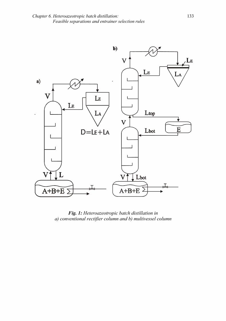
Chapter 6. Heteroazeotropic batch distillation: Feasible separations and entrainer selection rules
133
Fig. 1: Heteroazeotropic batch distillation in
a) conventional rectifier column and b) multivessel column

134
2. Feasibility analysis for the working example
In this section we present the principles of our feasibility analysis. The principles are general and apply to all mixtures studied in this paper. However, a working example is used for illustrative reasons. First, we discuss feasibility for mode I and II of heteroazeotropic batch distillation mentioned in the introduction. Second, feasibility for separation strategies A and B in the rectifier column and also in the multivessel column is addressed. Suppose that an initial close-boiling binary mixture (AB) is to be separated. Components A and B are the so-called original components and the mixture AB is the so-called original mixture. Component A (light) is considered to have lower boiling point than component B (heavy). To facilitate separation, a light entrainer (E) that forms a binary heteroazeotrope (AzEA) with the original component A is added. The heteroazeotrope AzEA becomes the unstable node (o) of the distillation line map, components E and A become saddles (∆) and the original component B becomes the stable node (●), as shown in Fig. 2. This working mixture belongs to Serafimov’s class 1.0-1a. No distillation boundary exists but the ternary diagram is divided in two batch distillation regions (a) and (b) by the line B-AzEA running from the heteroazeotrope AzEA to the original component B.
2.1 Feasibility for Modes I and II
Both modes of heteroazeotropic batch distillation require an initial start-up period with total reflux in order to establish the composition profile in the column. The differences of the two modes start after this initial start-up period. When the process is performed under Mode I, the column is refluxed with the heteroazeotrope during the whole operation and the distillation step continues until the whole heteroazeotrope AzEA is collected in the decanter. Only, when the distillation part is over we introduce the liquid-liquid split that allows us to “break” the azeotrope and recover an entrainer-rich phase LE and an entrainer-lean (product) phase LA rich in the original component A. The other original component B is recovered pure in the still. Since the liquid-liquid split happens post-operationally, Mode I of the process is governed by the rules of homoazeotropic batch distillation. This is illustrated by the feasibility region shown in Fig. 2a, which indicates that the process is feasible only in area (a). This is the region described in the feasibility rules by Skouras and Skogestad (2004) for the multivessel column. However, their process is actually Mode II and consequently, the feasibility analysis is partially incorrect and applies only to the start-up step of the process. The additional possibilities obtained during the main step (Mode II) were not considered.

Chapter 6. Heteroazeotropic batch distillation: Feasible separations and entrainer selection rules
135
Duessel and Stichlmair (1995) adopted Mode I for the separation of water (A) - pyridine (B) by using toluene (E) as a heteroazeotropic entrainer. The feed F was placed exactly on the straight line B-AzEA and a single rectification step was required since they could reach the pure component B vertex by removing the heteroazeotrope AzEA during the whole process. The main disadvantage of Mode I is that large amounts of added entrainer E are required. On the other hand, Mode II allows operation also in a part of region (b) where smaller amounts of entrainer E are required. In Mode II the splitting of the heteroazeotrope in the decanter is introduced during the distillation step, which allows us to reflux and withdraw/accumulate any combination of these two phases in the decanter. The most straightforward version of Mode II is to reflux the entrainer-rich phase LE only, while the entrainer-lean LA phase is withdrawn (open operation) or accumulated in the decanter (closed operation). Thus, Mode II is a flexible process, governed by special laws and some limitations on the feasible regions for Mode I are not valid for Mode II. Fig. 2b illustrates these additional possibilities. The process under Mode II is feasible also in the part of region (b) limited by the straight line B-LA connecting the still product B and the entrainer-lean phase LA. Rodriguez et al. (2002) described Mode II of the process with feeds F placed exactly on the straight line B-LA. One rectification step was then required since they could reach the pure component B vertex by removing the entrainer-lean phase LA during the whole process. The feasibility analysis of Modla et al. (2003) agrees with the above findings even though the terminology used is different. They use the term “total reflux” for indicating Mode I and the term “finite reflux” for Mode II. The authors mention “it can be stated that the minimum amount of the entrainer decreases if, instead of the heteroazeotrope, the distillate is only withdrawn from the A-rich phase”. In Mode I, the minimum amount of entrainer lies on the line B-AzEA while in mode II, lies on the line B-LA. This issue is illustrated in Fig. 4 in Modla et al..

136
E
A B
AzEA
LE
LA
E
A B
AzEA
LE
LA
Mode I Mode II
Serafimov’s class 1.0-1a
a
b
a
b
a) b)
Fig. 2: Feasible regions (shaded) for Modes I and II of the process
2.2 Feasibility in the rectifier column
The rest of the paper focuses at Mode II of heteroazeotropic batch distillation with reflux of the entrainer-rich phase (LE) only. Koehler et al. (1995) presented two separation strategies A and B for the rectifier column, which were analysed in more details by Skouras et al. (2004). Both strategies can be realised in the open or closed rectifier. We address now feasibility issues and illustrate feasible regions for both strategies. The same working example (Serafimov’s class 1.0-1a) as before is used.
Strategy A
This strategy requires output/accumulation of one phase at the decanter at a time. Generally, with an arbitrary amount of entrainer E, the process requires two steps; product recovery step (1st step) and entrainer recovery step (2nd step). In the first “product recovery” step, component A is recovered with total reflux of the entrainer-rich phase LE. A binary mixture S1 of components B and E remains in the still at the end of this step while the entrainer-lean phase LA is recovered in the decanter Feasibility during this step requires that (see Fig. 3a):

Chapter 6. Heteroazeotropic batch distillation: Feasible separations and entrainer selection rules
137
1. Mass balance line: The final still composition (S1) is connected with the feed composition (F) and the composition of the entrainer-lean phase (LA) by a straight line. 2. Composition profile: The final still composition (S1) is connected with the composition of the reflux (LE) by a distillation line. In the second “entrainer recovery” step, pure entrainer E is recovered in the decanter and pure component B is recovered in the still. Reflux of pure entrainer E is applied during this step. Feasibility during this step requires (see Fig. 3b): 1. Mass balance line: The final still composition (B) is connected with the feed composition (S1) and the composition of the pure entrainer (E) by a straight line. 2. Composition profile: The final still composition (B) is connected with the composition of the reflux (E) by a distillation line.
E
AB
LA
LE
AzEA
F
a) E
AB
LA
LE
AzEAS1
b)
mass balancebinodal curve
composition profile
Fig. 3: Feasibility for strategy A in the rectifier column a) product recovery step (1st step) and b) entrainer recovery step (2nd step)

138
Strategy B
Strategy B uses partial reflux of the entrainer-rich phase LE and output/accumulation of both the entrainer-lean LA and the entrainer-rich phase LE. Pure original component B is recovered in the still at the end of the process. Feasibility for strategy B requires that (see Fig. 4): 1. Mass balance line: The final still composition (B) is connected with the feed composition (F) and the total composition (D) of the entrainer-lean (LA) and entrainer-rich phase withdrawn/accumulated in the decanter by a straight line. 2. Composition profile: The final still composition (B) is connected with the composition of the reflux (LE) by a distillation line.
E
AB
LA
LE
AzEA
F
D=L +LE A
mass balancebinodal curve
composition profile
Fig. 4: Feasibility for strategy B in the rectifier column

Chapter 6. Heteroazeotropic batch distillation: Feasible separations and entrainer selection rules
139
Strategy A has the advantage that it allows the recovery of pure entrainer E during the second step. Fig. 5a illustrates the feasibility region when strategy A is implemented. The whole BLAE triangle, that is, the whole feasibility region under Mode II, is available under strategy A. Strategy A should be adopted when we want to recover all three components from a ternary heteroazeotropic mixture. In strategy B the original component A is recovered at the composition of the entrainer-lean phase LA, as in strategy A. However, the entrainer E can only be recovered at the composition of the entrainer-rich phase LE and not pure entrainer as in strategy A. This limitation of strategy B is illustrated in Fig. 5b, where we see that the feasibility region is limited to the triangle BLALE. A feed F inside the triangle BLEE cannot be separated by strategy B but it can be separated by strategy A. Strategy B should be adopted when separating a binary original mixture AB by adding a heteroazeotropic entrainer E because in this case we are, most likely, not interested in recovering pure entrainer.
AzEA
E
B A
AzEA
E
B A
LE
LA
LE
LA
Strategy A Strategy B
Serafimov’s class 1.0-1a
a) b)
Fig. 5: Feasible regions (shaded) for separation strategies A and B in the rectifier

140
2.3 Feasibility in the multivessel column
The separation in the multivessel column as described by Skouras et al. (2004) is illustrated in Fig. 1b. The entrainer-rich phase LE is totally refluxed and only the entrainer-lean phase LA is withdrawn/accumulated in the decanter. For our working example pure entrainer E is recovered in the middle vessel and pure component B in the still. This operation of the column is shown in Fig. 1b and resembles strategy A in the rectifier column. Strategy A performs the separation in two steps sequentially in time, while in the multivessel column both steps are performed simultaneously in the rectifying and stripping section of the column. The products are the same for both processes; entrainer-lean phase LA, pure entrainer E and pure original component B. Consequently, the feasible region for the multivessel column is the same as for strategy A, shown in Fig. 5a. Feasibility in the multivessel column requires that (see Fig. 6): 1. Mass balance triangle: The feed composition (F) lies in the triangle spanned by the final still composition (B), the middle vessel composition (E) and the entrainer-lean composition (LA) withdrawn/accumulated in the decanter. 2. Composition profile: The final still composition (B) is connected with the composition of the reflux (LE) by a distillation line.
E
AB
LA
LE
AzEA
F
rectifying profile
rectifying profile
mass balancebinodal curve
composition profile
Fig. 6: Feasibility in the multivessel column

Chapter 6. Heteroazeotropic batch distillation: Feasible separations and entrainer selection rules
141
3. General feasibility conditions
In this section we attempt to address the question: “Given a distillation line map along with the binodal curve of a ternary mixture, how can we check if the separation is feasible”? We want to know, at a preliminary stage, if a separation is feasible without doing all the detailed feasibility analysis. Of course, if the separation is feasible, the detailed analysis should be done, in a later stage, in order to identify feasible regions, initial feed location, minimum amount of added entrainer, etc. Thus, we summarise the findings from the previous section and we formulate two general conditions which are valid for both the rectifier and the multivessel column. These conditions enable us to investigate feasibility based on minimum information coming from the distillation line map along with the binodal curve of the ternary mixture. In order to develop such feasibility conditions based on minimum information, the assumptions of total reflux/total reboil ratios and infinite number of stages are necessary. Under these assumptions, the distillation line map and the binodal curve of the mixture provide all the necessary information for checking feasibility. These working assumptions are tools that allow us to address feasibility theoretically and relaxing them is not affecting the results of the feasibility analysis. We will come back to this issue later. The feasibility conditions formulated below relate to Mode II of heteroazeotropic batch distillation with reflux of the entrainer-rich phase only. The rules are valid for both the rectifier and the multivessel column. This is dictated by the fact that the separation in the multivessel column resembles the separation strategy A in the rectifier column. Moreover, the conditions are valid for both strategies A and B in the rectifier column. This is because it is not allowed to perform the two process steps (product recovery and entrainer recovery) in different columns, as mentioned before. If it was allowed to perform the 2nd (entrainer recovery) step of strategy A in another column, then it would be more flexible than strategy B and the feasibility conditions would be different. Let us continue now with the formulation of the feasibility conditions. Assume that we want to separate a binary azeotropic or close-boiling mixture (AB) by the addition of a heteroazeotropic entrainer (E). The resulting ternary mixture (A+B+E) is introduced to the still of the rectifier or the multivessel column equipped with a decanter for accommodating the phase splitting at the top, as shown in Fig. 1. An initial start-up period is needed in order to build-up the composition profile in the column and collect some of the heteroazeotrope in the decanter. This period

142
is run under total reflux and the entire mixed phases in the decanter are refluxed. The only feasibility requirement during the start-up period is that the initial feed has to be located in a region where the heteroazeotrope is the unstable node so it will boil overhead. When some of the heteroazeotrope is collected in the decanter, the main period of the process can start. The entrainer-rich phase (LE) is refluxed to the column. As mentioned before, the reflux can be total (strategy A in the rectifier or the multivessel column) or partial (strategy B in the rectifier column) and the immiscible phases in the decanter can be either withdrawn (open operation) or accumulated (closed operation). The feasibility requirement during the main period is that it exists a column profile connecting the still composition to that of the reflux composition LE at the top of the column. At total reflux the column composition profile is represented by a distillation line. As a consequence of the above, two feasibility conditions are formulated. Feasibility condition 1: There should exist a feed region where the heteroazeotrope is the unstable node such that it boils overhead and starts accumulating in the decanter. Feasibility condition 2: There should, at steady state, exist a distillation line connecting the reflux composition LE with the still product composition B or A in the direction of increasing temperature from LE to B or A. The assumption of infinite number of stages is used in order to secure that the stationary points of the distillation line map are achieved in the column, e.g. the heteroazeotrope is collected in the decanter, pure component B or A is recovered in the still, etc. This assumption can be relaxed, since we can always use the finite number of stages assuring the desired product specifications. The assumption of total reflux/reboil ratios enables us to use the distillation lines instead of calculating the exact column profile. In simple words, this assumption implies that the final column profile lies on the edge between the still composition B and the reflux composition LE, as shown for example in Figs. 4 and 6. Of course, the real separation is performed at finite reflux, which means that the final column profile would lie near the edge B-LE depending on the reflux and the number of stages. Thus, this assumption can be also relaxed without loss of the validity of our analysis.

Chapter 6. Heteroazeotropic batch distillation: Feasible separations and entrainer selection rules
143
4. Feasibility results for various cases
In this section the validity of feasibility conditions 1 and 2 is checked for the distillation line maps of various mixtures. If the conditions are satisfied the separation is feasible. The following three general cases were studied: Case a: The original mixture (AB) is close-boiling. Ten cases were analysed and the results are shown in Table 1. Case b: The original mixture (AB) has a minimum-boiling homoazeotrope (AzAB). Nine cases were analysed and the results are shown in Table 2. Case c: The original mixture (AB) has a maximum-boiling homoazeotrope (AzAB). Seven cases were analysed and the results are shown in Table 3. We did not analyse mixtures where: N1. The formed heteroazeotrope after the addition of the entrainer is not an unstable node of the distillation line map. In such a case it is impossible to recover the heteroazeotrope in the top of the column by a rectification process. N2. The original mixture (AB) is heteroazeotropic. In this case we can perform a binary heteroazeotropic distillation and recover the original components. N3. The entrainer has a boiling point between the boiling points of the original components (intermediate entrainer). The possibilities of finding such entrainers are rather limited since close-boiling and azeotropic mixtures do not usually differ by more than about 30˚C in their boiling points (Perry et al., 1997). N4. Mixtures that are unlikely to occur in practice. All mixtures are classified under one of the 26 Serafimov’s classes. Hilmen et al. (2002) and Kiva et al. (2003) pointed out that 10 of these classes have not been reported in the literature. In addition, one class applies only to zeotropic mixtures. Thus, a total of 15 classes are included in this study. The results for cases a-c are summarised in Tables 1-3, respectively. The first column refers to the properties of the added entrainer E. In the second column the distillation line map along with the binodal curve of the ternary mixture is shown. The arrows in the maps indicate the direction of increasing temperature. The third column classifies the mixture according to Serafimov’s classification. In the fifth column a “YES” indicates feasibility and the entrainer is acceptable, while a “NO” indicates infeasibility. In the last column we investigate if it is possible to recover pure original component A or B from the entrainer-lean phase LA or LB by subsequent distillation steps. Thus, a “YES” under the last column titled “pure components” means that we can recover pure A or B and a “NO” means that we cannot recover pure components in subsequent steps. Additional information about the expected final products in the vessels are given in Table A in the Appendix. To illustrate the use of these diagrams we will look closer at some subcases of cases a-c.

144
4.1 Case a: Original mixture (AB) is close-boiling
Separation of close-boiling mixtures into pure products requires high reflux ratios and high number of stages and the process often becomes uneconomical. Ten different cases, not excluded by N1-N4, were investigated (Cases a1-a10) and the results are shown in Table 1. The mixtures are classified under nine of Serafimov’s classes. Five of the studied cases lead to feasible separations. Case a1 was used as the working example (Figs. 3-6) and it is not further discussed. We will look closer to case a5 since it has some interesting features. Case a5: The added entrainer forms a heteroazeotrope AzEA with the light original component A and a minimum-boiling homoazeotrope AzEB with the heavy component B and the mixture is of Serafimov’s class 2.0-2b. There exist two distillation regions that are separated by a distillation boundary (unstable separatrix) running from the heteroazeotrope AzEA to the homoazeotrope AZEB. If we look at the distillation line map for case a5 in Table 1 and we check if feasibility condition 2 is fulfilled we can easily reach the conclusion that the condition is violated. There is no distillation line connecting the desired still product B and the entrainer-rich phase LE and the separation should be infeasible. Such a conclusion is however wrong. Condition 2 requires that such a connection should exist at steady state. In Table 1 we see that the reflux path (the path of the entrainer-rich phase LE) moves along the binodal curve from point LE to point LE´, which is the intersection point of the binodal curve and the distillation boundary. This means that the points LE´ and B are connected by a distillation line in the direction of increasing temperature from LE´ to B and thus, condition 2 is fulfilled at steady state. In addition, it is easy to check that condition 1 is also fulfilled and therefore the separation is feasible. The figure in Table 1 shows also the path of the entrainer-lean phase from LA to LA´. The steady state point LA´ is in equilibrium with the point LE´ and they belong to the same tie-line. The same behaviour with the reflux path moving along the binodal curve is encountered in cases a6, a9, b5, b6 and c4 (Tables 1-3). Skouras et al. (2004) presented rigorous simulations results for a mixture classified under Serafimov’s class 3.1-2 (case b6 in Table 2) and discussed this issue. However, we should note here that the reflux cannot always move freely along the binodal curve. The critical point of the binodal curve, that is the point where the distinction between coexisting liquid phases vanishes (Pham and Doherty, 1990b), limits the reflux on its movement. If the reflux “meets” the critical point before it reaches the intersection point of the binodal curve with the distillation boundary, then no liquid-liquid split is available anymore and thus the process is infeasible. Consequently, the feasibility in case a5, a6, a9, b5, b6 and c4 depends also in the interposition of the critical point with the intersection point of the binodal curve

Chapter 6. Heteroazeotropic batch distillation: Feasible separations and entrainer selection rules
145
with the distillation boundary. A brief introduction on the intersection of the distillation boundaries and the binodal curve is given by Kiva et al. (2003) where it seems that the distillation boundaries never goes through the critical point. However, based on this analysis, a general statement about where exactly the critical point is placed in comparison to the distillation boundaries cannot be made. One important difference between case a5 and our working example (case a1) is that it is not possible to recover pure entrainer E in case a5. This is because the binary edge EB in case a5 exhibits an additional stationary point, which is the homoazeotrope AzEB. This homoazeotrope is then recovered in the rectifier column during the 2nd (entrainer recovery) step or in the middle vessel of the multivessel column. In Table A in the Appendix, we give the final products in the vessels for all cases both for the rectifier and the multivessel column. Case a3: This is the case of a close-boiling mixture (AB) to be separated by the addition of a heavy entrainer (E) that forms a heteroazeotrope (AzEA) with the light original component (A). Case a3 is, according to our analysis, infeasible. Modla et al. (2003) studied feasibility for such a mixture and they reached the same conclusion: “If only one phase reflux is applied, the specified distillate composition cannot be reached from anywhere and the whole area of the triangle will be infeasible”. Note that only entrainer-rich phase reflux is considered in our work and this is, as mentioned in the introduction, one of the principal differences between our work and the one from Rodriguez et al. (2001).
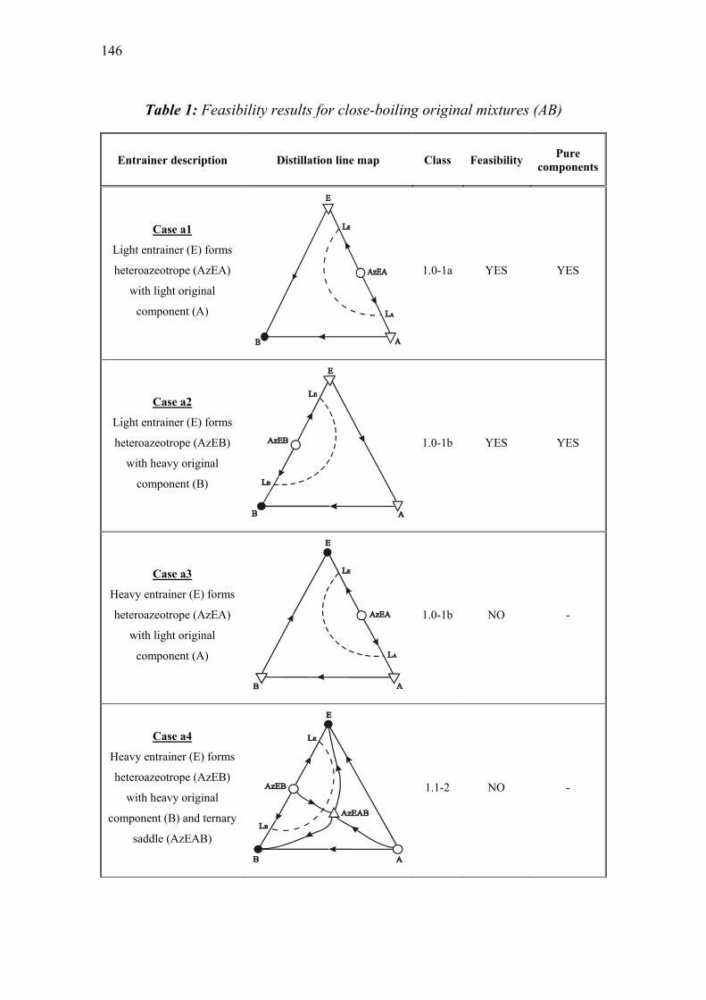
146
Table 1: Feasibility results for close-boiling original mixtures (AB)
Entrainer description Distillation line map Class Feasibility Pure components
Case a1
Light entrainer (E) forms
heteroazeotrope (AzEA)
with light original
component (A)
1.0-1a
YES
YES
Case a2
Light entrainer (E) forms
heteroazeotrope (AzEB)
with heavy original
component (B)
1.0-1b
YES
YES
Case a3
Heavy entrainer (E) forms
heteroazeotrope (AzEA)
with light original
component (A)
1.0-1b NO -
Case a4
Heavy entrainer (E) forms
heteroazeotrope (AzEB)
with heavy original
component (B) and ternary
saddle (AzEAB)
1.1-2 NO -
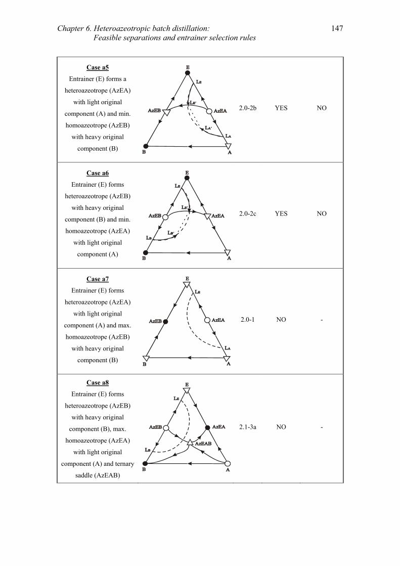
Chapter 6. Heteroazeotropic batch distillation: Feasible separations and entrainer selection rules
147
Case a5
Entrainer (E) forms a
heteroazeotrope (AzEA)
with light original
component (A) and min.
homoazeotrope (AzEB)
with heavy original
component (B)
2.0-2b YES NO
Case a6
Entrainer (E) forms
heteroazeotrope (AzEB)
with heavy original
component (B) and min.
homoazeotrope (AzEA)
with light original
component (A)
2.0-2c YES NO
Case a7
Entrainer (E) forms
heteroazeotrope (AzEA)
with light original
component (A) and max.
homoazeotrope (AzEB)
with heavy original
component (B)
2.0-1 NO -
Case a8
Entrainer (E) forms
heteroazeotrope (AzEB)
with heavy original
component (B), max.
homoazeotrope (AzEA)
with light original
component (A) and ternary
saddle (AzEAB)
2.1-3a NO -

148
Case a9
Entrainer (E) forms
heteroazeotrope (AzEA or
AzEB) with one original
component (Aor B), min.
homoazeotrope (AzEB or
AzEA) with the other (B or
A) and ternary
heteroazeotrope (AzEAB)
2.1-2b YES NO
Case a10
Entrainer (E) forms
heteroazeotrope (AzEA or
AzEB) with one original
component (Aor B), min.
homoazeotrope (AzEB or
AzEA) with the other (B or
A) and ternary saddle
(AzEAB)
2.1-3b NO -

Chapter 6. Heteroazeotropic batch distillation: Feasible separations and entrainer selection rules
149
4.2 Case b: Original mixture (AB) is minimum-boiling homoazeotropic
When the original mixture (AB) is azeotropic, there are two general cases that have to be studied. The first one is when the original mixture exhibits a minimum-boiling (min) homoazeotrope (case b), and the second is when the original mixture exhibits a maximum-boiling (max) homoazeotrope (case c). We look at case b first. Nine different cases, not excluded by N1-N4, were identified and are given in Table 2. The corresponding distillation line maps were classified under eight of Serafimov’s classes and four of them proved to be feasible. We further discuss case b2. Case b2: A light entrainer E is added to the original mixture AB that forms a heteroazeotrope AzEA with the light original component A. In addition a ternary saddle homoazeotrope AzEAB exists. There exist four distillation regions divided by four distillation boundaries. Two boundaries (stable separatrices) are running from the saddle ternary homoazeotrope AzEAB to the two original components A and B, while two boundaries (unstable separatrices) are running from the binary azeotropes AzEA and AzAB to the ternary saddle AzEAB. The mixture is of Serafimov’s class 2.1-3b and is interesting because of the ternary saddle homoazeotrope. It is easy to check that both feasibility conditions 1 and 2 are fulfilled. Indeed, the corresponding distillation line map in Table 2 shows that there exists a region in which the heteroazeotrope AzEA is the unstable node. Moreover, we can see that a distillation line exists that connects the reflux LE with the desired still product B in the direction of increasing temperature (see the arrows) from LE to B. Therefore, the separation and consequently the added entrainer are feasible. However, we have to point out that even if the separation B2 is feasible, this is the only case where an entrainer that leads to the formation of a ternary saddle homoazeotrope makes the process feasible. Tables 1-3 indicate that in all other cases where a ternary saddle is formed by the addition of an entrainer, like in cases a4, a8, a10, b4, b8, c3, c6 and c7 the separation is infeasible. Thus, our general advice is to avoid entrainers that lead to the formation of ternary saddle azeotropes.

150
Table 2: Feasibility results for minimum homoazeotropic original mixtures (AB)
Entrainer description Distillation line map Class Feasibility Pure components
Case b1
Light entrainer (E) forms
heteroazeotrope (AzEA or
AzEB) with one original
component (A or B)
2.0-2b YES YES
Case b2
Light entrainer (E) forms
heteroazeotrope (AzEA or
AzEB) with one original
component (A or B) and
ternary saddle (AzEAB)
2.1-3b YES YES
Case b3
Heavy entrainer (E) forms
heteroazeotrope (AzEA or
AzEB) with one original
component (A or B)
2.0-2c NO -
Case b4
Heavy entrainer (E) forms
heteroazeotrope (AzEA or
AzEB) with one original
component (A or B) and
ternary saddle (AzEAB)
2.1-3b NO -

Chapter 6. Heteroazeotropic batch distillation: Feasible separations and entrainer selection rules
151
Case b5
Entrainer (E) forms
heteroazeotrope (AzEA or
AzEB) with one original
component (A or B) and
min. homoazeotrope with
the other (AzEB or AzEA)
3.0-2 YES YES
Case b6
Entrainer (E) forms
heteroazeotrope (AzEA or
AzEB) with one original
component (A or B), min.
homoazeotrope with the
other (AzEB or AzEA)
and ternary
heteroazeotrope (AzEAB)
3.1-2 YES YES
Case b7
Entrainer (E) forms
heteroazeotrope (AzEA or
AzEB) with one original
component (A or B) and
max. homoazeotrope with
the other (AzEB or AzEA)
3.0-1b NO -
Case b8
Entrainer (E) forms
heteroazeotrope (AzEA or
AzEB) with one original
component (A or B), max.
homoazeotrope with the
other (AzEB or AzEA)
and ternary saddle
(AzEAB)
3.1-4 NO -
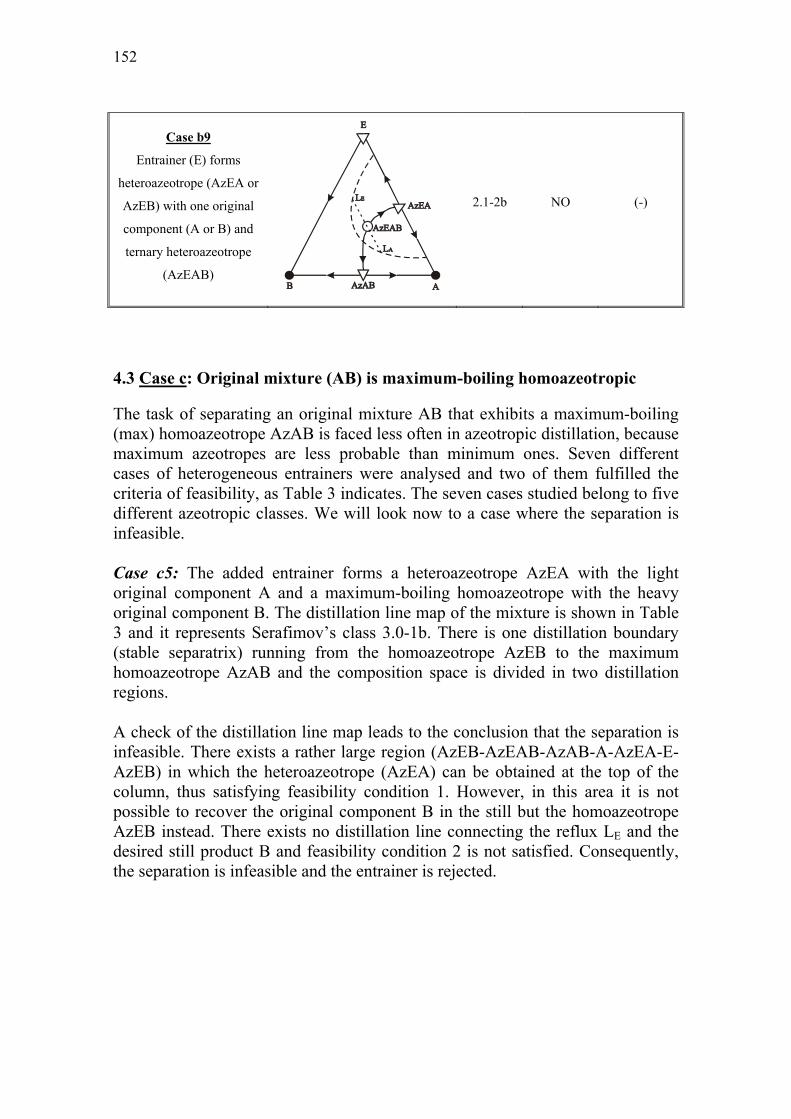
152
Case b9
Entrainer (E) forms
heteroazeotrope (AzEA or
AzEB) with one original
component (A or B) and
ternary heteroazeotrope
(AzEAB)
2.1-2b NO (-)
4.3 Case c: Original mixture (AB) is maximum-boiling homoazeotropic
The task of separating an original mixture AB that exhibits a maximum-boiling (max) homoazeotrope AzAB is faced less often in azeotropic distillation, because maximum azeotropes are less probable than minimum ones. Seven different cases of heterogeneous entrainers were analysed and two of them fulfilled the criteria of feasibility, as Table 3 indicates. The seven cases studied belong to five different azeotropic classes. We will look now to a case where the separation is infeasible.
Case c5: The added entrainer forms a heteroazeotrope AzEA with the light original component A and a maximum-boiling homoazeotrope with the heavy original component B. The distillation line map of the mixture is shown in Table 3 and it represents Serafimov’s class 3.0-1b. There is one distillation boundary (stable separatrix) running from the homoazeotrope AzEB to the maximum homoazeotrope AzAB and the composition space is divided in two distillation regions. A check of the distillation line map leads to the conclusion that the separation is infeasible. There exists a rather large region (AzEB-AzEAB-AzAB-A-AzEA-E-AzEB) in which the heteroazeotrope (AzEA) can be obtained at the top of the column, thus satisfying feasibility condition 1. However, in this area it is not possible to recover the original component B in the still but the homoazeotrope AzEB instead. There exists no distillation line connecting the reflux LE and the desired still product B and feasibility condition 2 is not satisfied. Consequently, the separation is infeasible and the entrainer is rejected.

Chapter 6. Heteroazeotropic batch distillation: Feasible separations and entrainer selection rules
153
Table 3: Feasibility results for maximum homoazeotropic original mixtures (AB)
Entrainer description Distillation line map Class Feasibility Pure
components
Case c1
Light entrainer (E) forms
heteroazeotrope (AzEA or
AzEB) with one original
component (A or B)
2.0-1 YES YES
Case c2
Heavy entrainer (E) forms
heteroazeotrope (AzEA or
AzEB) with one original
component (A or B)
2.0-2a NO -
Case c3
Heavy entrainer (E) forms
heteroazeotrope (AzEA or
AzEB) with one original
component (A or B) and
ternary saddle (AzEAB)
2.1-3a NO -
Case c4
Entrainer (E) forms
heteroazeotrope (AzEA or
AzEB) with one original
component (A or B) and
min. homoazeotrope with
the other (AzEB or AzEA)
3.0-1b YES YES

154
Case c5
Entrainer (E) forms
heteroazeotrope (AzEA or
AzEB) with one original
component (A or B) and
max. homoazeotrope with
the other (AzEB or AzEA)
3.0-1b NO -
Case c6
Entrainer (E) forms
heteroazeotrope (AzEA or
AzEB) with one original
component (A or B), max.
homoazeotrope with the
other (AzEB or AzEA) and
ternary saddle (AzEAB)
3.1-4 NO -
Case c7
Entrainer (E) forms
heteroazeotrope (AzEA or
AzEB) with one original
component (A or B), min.
homoazeotrope with the
other (AzEB or AzEA) and
ternary saddle (AzEAB)
3.1-4 NO -
Chapter 6. Heteroazeotropic batch distillation: Feasible separations and entrainer selection rules
155
4.4 Pure original component from the entrainer-lean phase
As mentioned already, the original component A or B immiscible with the entrainer E and forming the heteroazeotrope is recovered at the composition of the liquid-liquid split LA or LB. The original component B or A miscible with the entrainer is recovered pure in the still. Our feasibility analysis did not cover the possibility of further purification of the entrainer-lean phase. In the last column of Tables 1-3 (under the title “pure components”), we consider this issue for all feasible separations. Case a1: This case served as the working example in this paper. As can be seen in Table A in the Appendix were we give the steady state products for both the rectifier and the multivessel column, the entrainer-lean phase LA, rich in the original component A, is recovered in the decanter. The other original component B is recovered pure in the still. The entrainer-lean phase LA is on the binary edge AE (see Table 1) and thus, it can be easily separated in a subsequent rectification step. The heteroazeotrope AzEA will then be the top product and pure component A will be the still product. Thus, case a1 is not only feasible but also both original components can be recovered pure. The last column in Table 1 indicates whether the original component (A or B) can be recovered in pure form from the entrainer-lean phase (LA or LB) in subsequent distillation steps. Case a5: As seen in Table A in the Appendix, pure component B is recovered in the still, while the entrainer-lean phase LA´ is recovered in the decanter. A subsequent rectification step for the ternary fraction LA´ (Table 1) will lead to the heteroazeotrope AzEA in the decanter, while the still path will end up in the binary edge AB. This means that we return to the close-boiling mixture AB that we wanted to separate initially. Thus, the process is feasible (we can recover B and LA´) but we cannot recover pure original component A from the entrainer-lean phase LA´ in the decanter. The ternary fraction LA´ has to be recycled to the next batch. Therefore, we have a “NO” in the last column of Table 1. The same happens with case a9 in Table 1. We cannot recover pure A from the ternary fraction LA´ Case a6: As we can see in Table A in the appendix, pure component A is recovered in the still and an entrainer-lean phase LB´ in the decanter. It is not possible to recover pure component B from the entrainer-lean phase LB´ with a subsequent rectification step, since this will lead back to the original close-boiling mixture AB (see Table 1). However, it would be possible to recover pure component B from the fraction LB´ in a batch stripper since component B is a stable node in the region where the fraction LB´ is located. Since batch strippers are not considered in this study, we have a “NO” in the last column of Table 1.

156
Case b2: In Table A in the Appendix we see that pure component B is recovered in the still, while an entrainer-lean phase LA in the binary edge EA (Table 1) is recovered in the decanter. A subsequent rectification step of the binary fraction LA can be used for recovering pure component A. Thus, further purification of the entrainer-lean phase is possible. Generally speaking, in all cases where the entrainer-lean phase LA or LB is a binary mixture it is possible to recover a pure component from this fraction. This happens in cases a1, a2, b1, b2 and c1. The situation is more complicated when the entrainer-lean phase is ternary, as cases a5, a6 and a9 indicated. Let us look at cases b5, b6 and c4. In these cases, the entrainer-lean phase LA´ is ternary and we want to check if it is possible to recover pure component A from such a fraction. Remember that this was not possible in cases a5, a6 and a9. In contrast such a further purification of the entrainer-lean phase LA´ is feasible in cases b5, b6 and c4. A subsequent rectification step will provide the heteroazeotrope in the top and a fraction in the binary edge AB in the bottom. This binary fraction AB can then be separated by a third rectification step in the original homoazeotrope AzAB and the pure original component A. In cases b5 and b6 the pure component A is recovered in the still, while in case c4 is recovered at the top.

Chapter 6. Heteroazeotropic batch distillation: Feasible separations and entrainer selection rules
157
5. Entrainer selection rules
The objective of this section is to address the following issue: “Formulate some simple rules that enable us to screen entrainers for the process with minimum effort”. Based on the feasibility conditions 1 and 2 in section 2 and the feasibility results in Tables 1-3, the following rules were formulated: Entrainer selection rule 1: The entrainer (E) should form a heteroazeotrope (AzEA or AzEB) with one of the original components (A or B) and/or a ternary heteroazeotrope (AzEAB). Entrainer selection rule 2: The vertex of the original component to be obtained in the still at steady state (A or B) should be connected with the steady state reflux point of the entrainer-rich phase (LE) with a distillation line (residue curve) in the direction of increasing temperature from the top of the column to the bottom (LE→A or LE→B). Among the two rules given above, rule 2 is the most important for the feasibility of the separation task. Whenever a separation is infeasible this rule is violated. Rule 1 is a necessary starting point for the heteroazeotropic distillation process. These rules refer to the feasibility of the separation task in one column (rectifier or multivessel) in order to recover one of the original components A or B with the entrainer-lean phase and the other component B or A pure in the still. The possibility of recovering pure original component from the entrainer-lean phase is not included in these rules. Moreover, the rules are valid for heteroazeotropic distillation under Mode II in the rectifier and the multivessel column with reflux of the entrainer-rich phase LE only and are independent of the separation strategy A or B employed. Different reflux policies at the top of the column e.g. reflux of both immiscible phases are governed by different feasibility rules. The entrainer selection rules are necessary but not sufficient conditions for the feasibility of the process. The successful realisation of a principally feasible separation always depends on the specific characteristics of the mixture, such as relative volatilities, azeotropic compositions, position of the binodal curve, curvature of the distillation boundaries, etc. The results in Tables 1-3 helped us to formulate, in addition to the entrainer selection rules, two guidelines that can be used in order to “screen out” infeasible entrainers.

158
Guideline 1: The entrainer (E) must not lead to the formation of maximum azeotropes with any of the original components (A or B). Guideline 2: The entrainer (E) should preferably not lead to the formation of a ternary saddle homoazeotrope. Guideline 1 is a consequence of the infeasibility of cases a7, a8, b7, b8 and c6. In all these cases the entrainer (E) forms a maximum homoazeotrope (AzEA or AzEB) with one of the original components (A or B) and the separation is infeasible. Thus, such entrainers should be rejected. Guideline 2 is a consequence of the analysis for cases a4, a8, a10, b2, b4, b8, c3, c6 and c7. In all these cases a ternary saddle homoazeotrope exists but the process is feasible only in case b2. Thus, it seems reasonable to avoid such entrainers unless we make sure that the entrainer is like the one described in case b2.

Chapter 6. Heteroazeotropic batch distillation: Feasible separations and entrainer selection rules
159
6. Conclusions
A feasibility analysis for heteroazeotropic batch distillation with reflux of the entrainer-rich phase only is provided for the rectifier and the multivessel column. The analysis is theoretical and based on the assumption of infinite reflux/reboil ratios and infinite number of stages. Under these assumptions only information coming from the distillation line map and the binodal curve of the mixture is necessary for investigating feasibility. Two feasibility conditions were proposed for this reason. The feasibility results provided the necessary information for the formulation of two simple entrainer selection rules that can be used for “screening” potential entrainers for the process. The entrainer selection task for the proposed heteroazeotropic batch distillation process can then be done in a systematic way.

160
7. Notation
A Light original component AzAB Binary azeotrope of the two original components A and B AzEA Binary azeotrope of the entrainer and the original component A AzEAB Ternary azeotrope of the entrainer and the original components A
and B AzEB Binary azeotrope of the entrainer and the original component B B Heavy original component D Final product in the decanter when strategy B is implemented E Entrainer F Feed LA Entrainer-lean phase LA´ Final product of the entrainer-lean phase in the decanter in cases
a5, a6, a9, b5, b6 and c4 LE Entrainer-rich phase LE´ Final product of the entrainer-rich phase in the decanter in cases
a5, a6, a9, b5, b6 and c4 S1 Still product at the end of the 1st step when strategy A is
implemented ∆ Saddle point of the distillation line map ● Stable node of the distillation line map O Unstable node of the distillation line map

Chapter 6. Heteroazeotropic batch distillation: Feasible separations and entrainer selection rules
161
APPENDIX
Table A: Final products for all cases in Tables 1-3
Case Rectifier column (Strategy B)
Rectifier column (strategy A) and
multivessel column
a1 LA, LE, B LA, E, B
a2 LB, LE, A LB, E, A
a3 Infeasible
a4 Infeasible
a5 LA´, LE´, B LA´ , AzEB, B
a6 LB´, LE´, A LB´ , AzEA, A
a7 Infeasible
a8 Infeasible
a9 LA´, LE´, B LA´ , AzEB, B
a10 Infeasible
b1 LA, LE, B LA, E, B
b2 LA, LE, B LA, E, B
b3 Infeasible
b4 Infeasible
b5 LA´, LE´, B LA´ , AzEB, B
b6 LA´, LE´, B LA´ , AzEB, B
b7 Infeasible
b8 Infeasible
b9 Infeasible
c1 LA, LE, B LA, E, B
c2 Infeasible
c3 Infeasible
c4 LA´, LE´, B LA´ , AzEB, B
c5 Infeasible
c6 Infeasible
c7 Infeasible

162
8. References
Duessel, R., Stichlmair, J., Separation of azeotropic mixtures by batch distillation using an entrainer, Computers and Chemical Engineering, S19, S113, (1995). Foucher, E.R., Doherty, M.F., Malone, M.F., Automatic screening of entrainers for homogeneous azeotropic distillation, Ind. Eng. Chem. Res., 30, 760, (1991). Furzer, I.A., Synthesis of entrainers in heteroazeotropic distillation systems, The Canadian Journal of Chemical Engineering, 72, 358, (1994). Hilmen, E.K., Kiva, V.N., Skogestad, S., Topology of ternary VLE diagrams: elementary cells, AIChE J, 48 (4), 752, (2002). Kiva, V.N., Hilmen, E.K., Skogestad, S., Azeotropic phase equilibrium diagrams: a survey, Chemical Engineering Science, 58, 1903, (2003). Koehler, J., Haverkamp, H., Schadler, N., Zur diskontinuierlichen Rektifikation azeotroper Gemische mit Hilfsstoffeinsatz, Chem.-Ing.-Tech, 67 (8), 967, (1995). Matsuyama, H., Nishimura, H., Topological and thermodynamic classification of ternary vapor-liquid equilibria, J. Chem. Eng. Jpn., 10 (3), 181, (1977). Modla, G., Lang, P., Kotai, B., Molnar, K., Batch heteroazeotropic rectification of a low α mixture under continuous entrainer feeding, AIChE J., 49(10), 2533, (2003). Perry, R. H., Green, D.W., Maloney, J.O., Perry’s chemical engineer’s handbook, 7th ed., McGraw-Hill, New York, 13ff, (1997). Pham, H.N., Doherty, M.F., Design and synthesis of heterogeneous azeotropic distillations-III. Column sequences, Chemical Engineering Science, 45 (7), 1845, (1990a). Pham, H.N., Doherty, M.F., Design and synthesis of heterogeneous azeotropic distillations-I. Heterogeneous phase diagrams, Chemical Engineering Science, 45 (7), 1823, (1990b). Rodriguez-Donis, I., Gerbaud, V., Joulia, X., Heterogeneous entrainer selection for the separation of azeotropic and close boiling temperature mixtures by heterogeneous batch distillation, Ind. Eng. Res., 40, 4935, (2001). Skouras, S., Kiva, V., Skogestad, S., Heteroazeotropic batch distillation. Process analysis and simulation results, AIChE J., (in review), (2004).

Chapter 6. Heteroazeotropic batch distillation: Feasible separations and entrainer selection rules
163
Skouras, S., Skogestad, S., Separation of ternary heteroazeotropic mixtures in a closed multivessel batch distillation-decanter hybrid, Chemical Engineering and Processing (Special Issue), 43 (3), 291, (2004).


165
Chapter 7
CONCLUDING REMARKS AND
SUGGESTIONS FOR FUTURE WORK
1. Concluding remarks
This thesis offers a critical evaluation of the heteroazeotropic distillation process mainly in closed batch distillation column configurations. Feasibility issues, conceptual analysis and operation aspects of the process are discussed throughout the study. The main contributions of this thesis, separately for each chapter, are summarised below:
Chapter 2: A case study for a zeotropic mixture showed that the elimination of the vapour bypass in the multivessel column can improve the composition dynamics in the middle vessel significantly. 30% time savings are achieved with the so-called modified multivessel column (without the vapour bypass) compared with the conventional one (with the vapour bypass).
Chapter 3: The separation of ternary heterogeneous azeotropic mixtures is feasible in a closed multivessel batch distillation-decanter hybrid. The feasibility issues are addressed both theoretically and by detailed simulations for mixtures classified under Serafimov’s classes 1.0-2, 1.0-1a and 2.0-2b.
Chapter 4: A critical evaluation of the separation of ternary heteroazeotropic mixtures in different closed batch column configurations based on the time requirements for each separation is presented. The results from the study for various azeotropic classes and practical considerations indicate the conventional multivessel (with the vapour bypass) as the best alternative for heteroazeotropic separations of mixtures classified under Serafimov’s classes 1.0-2, 1.0-1a and 2.0-2b.
Chapter 5: The separation of binary close-boiling and azeotropic mixtures by the addition of a heteroazeotropic entrainer is addressed in batch rectifier and multivessel configurations. An analysis of the process is presented that leads to better understanding of the issues to be addressed for the easy and practical operation of the column. Dynamic simulations for mixtures classified under Serafimov’s classes 2.0-2b and 3.1-2 verify the theoretical findings and illustrate the flexibility of the process.

166
Chapter 6: A theoretical feasibility analysis for the separation of close-boiling and azeotropic (minimum- and maximum-boiling) binary mixtures by the addition of a heteroazeotropic entrainer is addressed, based on information coming solely from the distillation line or residue curve map along with the binodal curve of the ternary mixture. Three simple rules are then proposed which allow us to “screen” entrainers for heteroazeotropic batch distillation with minimum efforts. 2. Suggestions for future work
According to our opinion, a future work in the area batch azeotropic distillation may treat some of the following topics:
1. A more detailed treatment of the issues mentioned in chapters 2 and 4 regarding the time requirements in different batch columns. The formulation of an optimization problem, with a more rigorous modeling of the distillation columns and usage of different objective functions (energy demands, total annual cost, etc), will provide a more comprehensive comparison and give a better overview of the advantages and drawbacks for each column configuration.
2. Experimental verification of the processes described in chapter 3 and 5 for both the rectifier and the multivessel column can provide insight into more practical issues regarding to the operation of the columns. More specific, it would be interesting to investigate the effect of the initial feed distribution in the vessels, the effect of the controllers’ setpoints and the effect of the column holdup on the separation performance of each column. In addition, such an experimental study will certainly be more interesting for the industry and the practitioners in the area of azeotropic distillation.
3. We mentioned in this study that heteroazeotropic distillation requires in general two periods (steps); a) a build-up period for establishing the composition profile in the column and accumulate the heteroazeotrope in the decanter and b) a decanting period where we start refluxing one of the immiscible phases in the decanter. However, no systematic try was done for deciding when it is best in terms of time requirements or separation performance to switch between these two periods. The importance of this issue can be addressed either by simulations or experimentally. Moreover, another start-up policy can be alternatively implemented. Some of the initial feed, inside the two-phase region (see for example the feed F in Fig. 5 in chapter 5), is directly placed in the decanter and the second (decanting) period can start at once since the two immiscible phases are already available in the decanter. Such an alternative policy was not studied here but it worths further investigation because we believe it can lead to less time requirements for some mixtures.

Chapter 7: Concluding remarks and suggestions for future work 167
4. The rather “new” process of heteroextractive distillation mentioned in the introductory chapter is a powerful method of separating azeotropic mixtures that has lately received much attention. However, a systematic analysis of the process, as is done for heteroazeotropic distillation in chapter 5, is not yet provided in the literature. Moreover, the performance of multivessel configurations for this process has not yet been studied. It would be useful to see some work done for this promising process.
5. Finally, we believe that a critical evaluation of the three most promising processes for azeotropic batch distillation, namely, heteroazeotropic distillation, extractive distillation and heteroextractive distillation should be done based on an industrial case study. Such a study could probably consider both conventional batch configurations (rectifiers) and multivessel configurations.


169
Appendix
Description of the model This appendix contains a description of the dynamic model for the closed rectifier (2-vessel) column and the closed multivessel (3-vessels) column used in the thesis. A short description of the model is given also at the end of each chapter. All simulations were done in Matlab and the corresponding files are available at the homepage of S. Skogestad: http://www.nt.ntnu.no/users/skoge. 1. Model assumptions
The model is based on the following assumptions: 1. Staged distillation columns (stages numbered from the top to the bottom) 2. Perfect mixing and equilibrium in all stages and in all vessels 3. No vapour holdup on the stages 4. Constant molar liquid holdup on the stages (column holdup ≈ 2% of the feed) 5. Constant molar vapour and liquid flows in the column sections (simplified energy balances) 6. Constant pressure in the column (P=1atm) 7. Total condenser 8. VLE calculations in the column sections 9. LLE only in the decanter. Liquid-liquid splits at the decanter temperature. 2. Model equations
Mass balances
The total and component mass balances for the conventional multivessel column (with the vapour bypass in the middle vessel) are described by the following equations:
Top vessel or decanter:
1 ´TT
dM V Ldt= − (A.1)
,1 1, ,´T T j
j T T j
dM xV y L x
dt= − (A.2)

170
Rectifying section (stage i = 1,…, N1):
1 10 i i i iL V L V− += + − − (A.3) ,
1 1, 1 1, , ,i j
i i i j i i j i i j i i j
dxM L x V y L x V y
dt − − + += + − − (A.4)
Middle vessel:
1 ´MN M
dM L Ldt= − (A.5)
,1 1, ,´M M j
N N j M M j
dM xL x L x
dt= − (A.6)
Stripping section (stage i = 1,…, N2):
1 10 i i i iL V L V− += + − − (A.7) ,
1 1, 1 1, , ,i j
i i i j i i j i i j i i j
dxM L x V y L x V y
dt − − + += + − − (A.8)
Bottom vessel:
2B
N BdM L V
dt= − (A.9)
,2 2, ,
B B jN N j B B j
dM xL x V x
dt= − (A.10)
For the modified multivessel where the vapour bypass is eliminated, the material balances for the middle vessel and the first stage of the rectifying and stripping section should be changed accordingly. The closed rectifier (2-vessel) column has only the rectifying column section and the mass balances are described by equations (A.1), (A.2), (A.3), (A.4), (A.9) and (A.10). Temperature and level controllers The liquid flows out of the top (LT) and middle vessel (LM) are given by proportional temperature controllers or by proportional-integral level controllers, which are described by the following equations:
P-temperature controller
0 ( )m setL L K T T= + − (A.11)

Appendix. Description of the model 171
PI-level controller
( ) ( )m set m setKL K M M M M dtτ
= − + −∫ (A.12)
In addition we do not allow the holdup in a vessel to become zero or negative which has obviously no physical meaning. Zero holdup in a vessel would result in zero liquid flows in the column section below this vessel. In order to achieve a smooth “turn off”, the liquid reflux out of the vessels determined by the controllers are modified by an exponential function, as described in Furlonge et al. (1999):
min´ [1 exp( )]ML L
M= − − (A.13)
Vapour-liquid equilibria (VLE) and liquid-liquid equilibria (LLE)
VLE
If ideal vapour phase is assumed, vapour-liquid equilibrium for component j = 1, 2, 3 is described by the equation:
sj j j jPy x Pγ= (A.14)
For the mixture ethyl acetate/water/acetic acid (chapters 3,4), dimerisation in the vapour phase for acetic acid has to be considered, as described in pages XIII-XIV in Gmehling and Onken (1977). The vapour pressures (Ps) are given by the Antoine equation:
10log jsj j
j
BP A
T C= −
+ (A.15)
The activity coefficients (γj) are given by the NRTL equation, which is described in Table 4 in Gmehling and Onken (1977).
LLE
Liquid-liquid equilibrium for component i=1,2,3 is described by the equation:
I I II IIj j j jx xγ γ= (A.16)
The activity coefficients (γj) are given by the NRTL equation, which is described in Table 4 in Gmehling and Onken (1977).

172
3. Notation
Latin letters A, B, C Coefficients for Antoine equation K Controller gain L Liquid flows [kmol h-1] L´ Modified liquid flows [kmol h-1] M Holdup on the stages [kmol] N Number of stages P Pressure [mmHg] T Temperature [ºC] t Time [h] V Vapour flows [kmol h-1] x Liquid compositions y Vapour compositions
Greek letters γ Activity coefficient τ Integration time [h]
Subscripts B Bottom vessel i Stage index j Component index M Middle vessel m Measured value min Minimum value set Setpoint value T Top (decanter) vessel 0 Nominal values
Superscripts I, II Liquid phases in equilibrium s saturated

Appendix. Description of the model 173
4. References
Furlonge, H.I., Pantelides, C.C., Sorensen, E., (1999), Optimal operation of multivessel batch distillation columns, AIChE J, 45 (4), 781-801. Gmehling, J., Onken, J., Vapor-liquid equilibrium data collection, DECHEMA Chemistry Data Series, Frankfurt am Main, (1977).
