hermhield applique installation method
TRANSCRIPT

INSTALLATION GUIDE
ThermShield Applique Installation Method
Applies to...• Actionair ThermShield FD
• Actionair ThermShield FD-C
Health and safety• This process must be undertaken by competent
persons. More than one person may be required to ensure the safe handling of large dampers and other materials. Use must be made of access equipment to ensure unsafe practices are not used to approach walls or difficult access areas.
• Standard site PPE should be used (minimum steel toe cap boots, hard hat); together with any protective eyewear, gloves and masks, when drilling or cutting is being undertaken. The latter should also be used when handing the wall construction materials, as defined by the material suppliers. If loud equipment is being used, hearing protection should be used.
• All waste materials should be collected and disposed of as defined by the relevant supplier.
• Actuators: All wiring should be carried out in accordance with the wiring details provided by the IEE and BS regulations and by a competent person. Care must be taken when installing and inspecting dampers, as they are likely to close without warning due to loss of electrical power or a temperature rise in the ductwork. This is their prime function. Do not insert any items, fingers or limbs between the blades. Larger dampers must be handled in accordance with current regulations and good practice due to weight.
ContentsApplies to... .......................................... 1Health and safety .................................. 1CE Installation Method Overview ..................... 2
Fire damper installation square openings ........ 3
Fire damper installation circular openings ....... 4
Rigid wall installation Applique installation frame .................................................................... 5
Flexible wall installation Applique installation frame .................................................................... 6
Minimal Seperation Dampers (square) ............. 7
Rigid wall installation Applique installation frame (circular) .................................................... 8
Flexible wall installation Applique installation frame (circular) .................................................... 9
Minimal Seperation Dampers (circular) ........... 10
Periodic maintenance .............................12 Actuators ............................................13Wiring Diagrams ...................................16Dimensional Data ..................................18Inspection and handover check sheet ........ 20

ThermShield Applique Installation Guide
2Swegon reserves the right to alter specifications. 20210615 - L00012
Application Installation Method
Rigid wall installation Applique installation frame Page 5
Flexible wall installation Applique installation frame Page 6
Minimal seperation damper installation (square) Page 7
Rigid wall installationApplique installation frame (circular) Page 8
Flexible wall installation Applique installation frame (circular)
Page 9
Minimal seperation damper installation (circular) Page 10
• For full classifications please refer to our Declaration of Performance (DoP), which can be found on our website.
• The methods in this manual should be followed to ensure a CE-marked installation.
• The instructions are based on the tested method using Actionair ThermShield PTC fire/smoke dampers.
• Our ThermShield dampers are designed to be used with fire separating elements to maintain fire compartments. The ThermShield is an actuated failsafe close damper with low smoke leakage, often referred to in the industry as a Fire/Smoke damper.
• Under the Fire Damper Product standard BS EN 15650 our Fire Damper products are tested to BS EN 1366-2 and classified under BS EN 13501-3.
CE Installation Method Overview
3 20210615 - L00012 Swegon reserves the right to alter specifications.
ThermShield Applique Installation Guide
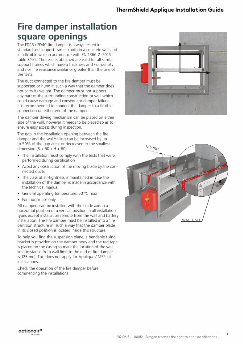
Fire damper installation square openingsThe FD25 / FD40 fire damper is always tested in standardised support frames (both in a concrete wall and in a flexible wall) in accordance with EN 1366-2: 2015 table 3/4/5. The results obtained are valid for all similar support frames which have a thickness and / or density and / or fire resistance similar or greater than the one of the tests.
The duct connected to the fire damper must be supported or hung in such a way that the damper does not carry its weight. The damper must not support any part of the surrounding construction or wall which could cause damage and consequent damper failure. It is recommended to connect the damper to a flexible connection on either end of the damper.
The damper driving mechanism can be placed on either side of the wall, however it needs to be placed so as to ensure easy access during inspection.
The gap in the installation opening between the fire damper and the wall/ceiling can be increased by up to 50% of the gap area, or decreased to the smallest dimension (B + 60 x H + 60)
• The installation must comply with the tests that were performed during certification
• Avoid any obstruction of the moving blade by the con-nected ducts
• The class of air-tightness is maintained in case the installation of the damper is made in accordance with the technical manual
• General operating temperature: 50 °C max
• For indoor use only
All dampers can be installed with the blade axis in a horizontal position or a vertical position in all installation types except installation remote from the wall and battery installation. The fire damper must be installed into a fire partition structure in such a way that the damper blade in its closed position is located inside this structure.
To help you find the suspension plane, a bendable fixing bracket is provided on the damper body and the red tape is placed on the casing to mark the location of the wall limit (distance from wall limit to the end of fire damper is 125mm). This does not apply for Applique / MF2 kit installations.
Check the operation of the fire damper before commencing the installation!
WALL LIMIT
125 mm

ThermShield Applique Installation Guide
4Swegon reserves the right to alter specifications. 20210615 - L00012
Fire damper installation circular openingsThe duct connected to the fire damper must be supported or hung in such a way that the damper does not carry its weight. The damper must not support any part of the surrounding construction or wall which could cause damage and consequent damper failure. It is recommended to connect the damper to a flexible connection on either end of the damper.
The damper driving mechanism can be placed on either side of the wall, however it needs to be placed so that it ensures an easy access during inspection.
Mounting is possible with the blade axis in horizontal or in vertical position
The installation must comply with the tests that were performed during certification
Avoid any obstruction of the moving blade by the connected ducts
The class of air-tightness is maintained in case the installation of the damper is made in accordance with the technical manual
General operating temperature: 50 °C max.
For indoor use only
The gap in the installation opening between the fire damper and the wall/ ceiling can be increased by up to 50% of the gap area, or decreased to the smallest dimension that is shown in the table:
Damper size - Ød [mm] Opening size - A (minimum)
Ød ≤ 160 Ød + 85 mm
180 ≤ Ød ≤ 315 Ød + 75 mm
355 ≤ Ød ≤ 450 Ød + 65 mm
Ød > 450 Ød + 55 mm
Installation in both, vertical and horizontal axis of rotation of the dampers blade is acceptable (with the axis angle 0 - 360°).
The fire damper must be installed into a fire partition structure in such a way that the damper blade in its closed position is located inside this structure (except for installation with MF installation frame).
To help you find the suspension plane, a bendable hinge is provided on the damper body and the red tape is placed on the casing to mark the location of the wall limit (distance from wall limit to the end of fire damper is 215mm). This does not apply for Applique/ MF1/ MF2 kit installations. Check the operation of the fire damper before commencing the installation!
WALL LIMIT
215 mm

5 20210615 - L00012 Swegon reserves the right to alter specifications.
ThermShield Applique Installation Guide
Rigid wall installation Applique installation frameDamper blade must be closed during installation!
The wall is composed of concrete blocks (minimum density of 550 kg/m³) or reinforced concrete (minimum density of 2200 kg/m³) and with a minimum thickness of 100 mm.
1. Prepare opening in the wall according to B (H) + 80 mm.
Damper blade must be closed during installation!
2. Insert fire damper into wall and fasten with screws (4 pcs, 4,8x60 mm).
Ensure that the damper is sufficiently supported.
Test the operation of the damper blade!
1 2

ThermShield Applique Installation Guide
6Swegon reserves the right to alter specifications. 20210615 - L00012
Flexible wall installation Applique installation frameDamper blade must be closed during installation!
The wall is composed of 2x2 plasterboard boards, 12,5 mm thick, installed on a steel frame construction. The interior of the wall is filled with mineral wool
(≥ 100 kg/m³). The minimum thickness of the wall is 100 mm.
* Create an opening according to the dimension of the fire damper and build the subframe according to the drawing.
1. Place the fire damper in the opening.
2. Fasten the fire damper with screws. (4 pcs, 4,8x60 mm).
Ensure that the damper is sufficiently supported.
Test the operation of the damper blade!
1 2

7 20210615 - L00012 Swegon reserves the right to alter specifications.
ThermShield Applique Installation Guide
FD25
Flexible Wall SubframeWhen installing the fire dampers in the flexible walls it is necessary to make a metal subframe onto which the damper will be fixed with screws. Subframe should be prepared according to the drawings below.
Support for Installation with MortarIn fire damper installations with mortar, it may be neces-sary to use wooden supports to prevent the casing from deforming while mortar is getting hardened.
Before filling the gap between wall and fire damper, close the damper blade and install the wooden supports as seen in the drawings below.
Place the wooden support as close as possible to the fire damper blade!
(B+80)
(H+
80)
(B+80)/2
FD40
(H+
80)
(B+80)

ThermShield Applique Installation Guide
8Swegon reserves the right to alter specifications. 20210615 - L00012
Rigid wall installationApplique installation frameDamper blade must be closed during installation!
The wall is composed of concrete blocks (minimum density of 550 kg/m³) or reinforced concrete (minimum density of 2200 kg/m³) and with a minimum thickness of 100 mm.
1. Create a wall opening according to the dimensions in the table below.
2. Insert fire damper into wall and fasten with screws (8 pcs, 4,8x60 mm).
Ensure that the damper is sufficiently supported.
Test the operation of the damper blade!
Wall opening dimensions
Damper diameter Ød [mm]
Applique frame diameter ØD [mm] Wall opening [mm]
100 Ød + 105 mm Ød + 115 mm125-180 Ød + 95 mm Ød + 105 mm200-315 Ød + 80 mm Ød + 90 mm
1 2

9 20210615 - L00012 Swegon reserves the right to alter specifications.
ThermShield Applique Installation Guide
Flexible wall installation Applique installation frameDamper blade must be closed during installation!
The wall is composed of 2x2 plasterboard boards, 12,5 mm thick, installed on a steel frame construction. The interior of the wall is filled with mineral wool
(≥ 100 kg/m³). The minimum thickness of the wall is 100 mm.
* Create an opening according to the table below and build the subframe according to the drawing, see page 10. 1. Place the fire damper in the opening.
2. Fasten the fire damper with screws
(8 pcs, 4,8x60 mm).
Ensure that the damper is sufficiently supported.
Test the operation of the damper blade!
Wall opening dimensions
Damper diameter Ød [mm]
Applique frame diameter ØD [mm] Wall opening [mm]
100 Ød + 105 mm Ød + 115 mm125-180 Ød + 95 mm Ød + 105 mm200-315 Ød + 80 mm Ød + 90 mm
1 2

ThermShield Applique Installation Guide
10Swegon reserves the right to alter specifications. 20210615 - L00012
Minimal seperation damper installation (circular)Damper blade must be closed during installation!
Firebatt- Mineral wool
1*. Prepare opening in the wall according to the installa-tion type.
(Firebatt installation- build the subframe).
Mortar- Gypsum blocks
1. Prepare opening in the wall, see page 3.
Fire damper can be installed with minimal distance of 30 mm between wall/ceiling and 30 mm from other dam-pers.
2. Insert the fire dampers into the wall and fill the space between the casings with mineral wool (140kg/m³) up to flanges.
30
30
30
30
Ød/2
30
1*
Fill the space between the wall/ceiling with mineral wool (140kg/m³) up to flanges.
3. Fill the rest of the wall openings in accordance with the relevant installation method.
Material compliant with the classification from DOP
Mineral wool 250mm wide (140 kg/m³)
*Minimal distances from another damper or wall/ceiling.1 2 3 4

11 20210615 - L00012 Swegon reserves the right to alter specifications.
ThermShield Applique Installation Guide
Flexible Wall SubframeWhen installing the fire dampers in the flexible walls it is necessary to make a metal subframe onto which the damper will be fixed with screws. Subframe should be prepared according to the drawings below.
FDC25 FDC40
FDC25-MF1 FDC40-MF2
(d+80)
Ø (d+80)
(d+
80)
(d+
80)
(d+80)
(d+80)/2
Ø (d+80)
(d+10)
(d+
10)
Ø (d+10)
(d+25)
(d+
25)
Ø (d+25)(d+25)/2

ThermShield Applique Installation Guide
12Swegon reserves the right to alter specifications. 20210615 - L00012
Periodic MaintenanceManufacturer Recommended Service Intervals• After commissioning and handover (see DW145 check
sheet), in order to remain compliant with 15650:2010, we recommend that you follow a regular service and inspection programme to ensure correct operation of dampers in the event the damper is required to actuate.
• In addition to regular physical inspections (in accordance with 15650:2010) we recommend using a dedicated damper control panel with a digital reporting mechanism (such as an Actionpac LNS system) to frequently monitor and report on regular remote damper testing.
• Ensure maintenance is performed in line with the latest best practice and relevant local or specialist guidance.
• Our recommended service intervals for life safety products are as follows:
Interval Action Competence
6 Months Check Actuator Wiring (if applicable) for Damage
Specialist Persons
6 Months Check Limit Switch Wiring (if applicable) for Damage
Specialist Persons
6 Months Check Damper Cleanliness, Clean and Lubricate if necessary.
Specialist Persons
6 Months Check Condition of Blades and Seals, report and rectify if necessary.
Specialist Persons
6 Months Check for blade obstructions Specialist Persons
6 Months Check Damper Release Mechanism (through activation or release of the ETR or Thermal Fuse Device)
Specialist Persons
6 Months Check damper is left in normal operational position after inspection.
Specialist Persons
Monthly Complete actuation of damper from control panel (if installed)and check all faults. Consult specialist persons to investigate any reported faults.
Facility Ma-nager
• *Specialist Persons: A recognised and experienced person with prior experience in the inspection and assessment of the functional safety of smoke and fire damper products. If in doubt, please consult with our technical support team for advice. To talk about our OEM maintenance inspections, contact our nationwide service team.
BS EN 15650:2010 - Ventilation for Buildings - Fire Dampers• Section 8.3 states regular testing/ inspection should
be undertaken to meet regulatory requirements, or at intervals not exceeding six months.
• A comprehensive example of the maintenance procedure is given in Annex D of the standard. Some
automatic systems may allow more frequent testing (48hr or less) and this may be required by a national standard.
Approved Document B, Volume 2• Clause 10.12 states adequate means of access must be
provided to allow inspection, testing and maintenance of both fire damper and its actuating mechanism.
BS 9999:2017 - Code of Practice for the Fire Safety in the Design, Management and Use of Buildings - Annex ISmoke Control Systems• For means of escape states actuation of the system
should be simulated once a week. It should be ensured that any fans and powered exhaust ventilators operate correctly, smoke dampers close (or open in some systems), natural exhaust ventilators open, automatic smoke curtains move into position, etc.
Three Monthly• In addition to the checks recommended in V.2, V.3 and
V.4, the actuation of all smoke control systems should be simulated once every three months. All zones should be separately tested and it should be ensured that any fans and powered exhaust ventilators operate correctly, smoke dampers close (or open in some systems) etc.
Yearly• In addition to the following checks should be made
for annual inspections and tests of the following to be carried out by competent persons, for any defects to be logged and the necessary action taken, and for certificates of testing to be obtained.
– Fire detection and fire alarm systems; – Self-contained luminaires with sealed batteries, if more
than 3 years old; – Sprinkler, drencher and watermist systems; – Smoke ventilators and smoke control systems;
– Fire dampers
BS 9999:2017 - Code of Practice for the Fire Safety in the Design, Management and Use of Buildings - Annex W• Maintenance of air conditioning and ventilation
equipment including air filters, motors, fire dampers and their controls, smoke detectors and alarms is of paramount importance both in preventing fire and in ensuring that measures taken to mitigate its consequences are effective when needed. Arrangements should be made for all fire dampers to be tested by a competent person on completion of the installation and at regular intervals not exceeding 2 years. They are to be repaired or replaced immediately if found to be faulty. Spring operated fire dampers should be tested annually and fire dampers in dust laden and similar atmospheres should be tested much more frequently, at periods suited to the degree of pollution.

13 20210615 - L00012 Swegon reserves the right to alter specifications.
ThermShield Applique Installation Guide
ActuatorsManual Actuators R, R-SManual operating mechanism, optionally with end swit-ches (R-S). In case of fire, the fire damper closes automa-tically. Damper closing can be initiated either by thermal fuse melting, or by manual activation on the operating mechanism. Upon closure, damper blade is locked in closed position and can only be opened manually. Ther-mal fuse melting point is 72 °C.
R25R25 (left) manual actuator is installed on FD25 fire dam-pers range from 100x200 to 800x600. It is available in version with (R-S) and without (R) end switches. End swit-ches and thermal fuse are easily replaceable and available as service parts.
R40R40 (right) manual actuator is installed on FD40 fire dam-pers from 800x600 to 1500x800. It is available in version with (R-S) and without (R) end switches. End switches and thermal fuse are easily replaceable and available as service parts.
Technical SpecificationsNominal voltage N/A
Power N/A
Switching capacity 1mA…500mA, 5VDC…48VDC
Blade closing time Spring: 1 sec
Blade opening time Manual
Manual activation Release button on the casing
Degree of protection IP 42
Ambient temperature range
min. -30 °C, max. 50 °C
Ambient humidity95% r.h., non-condensing
Service life Min. 30,000 cycles
Maintenance Maintenance-free (see page 12)
Weight R25/R40 0,5 kg / 1,7 kg

ThermShield Applique Installation Guide
14Swegon reserves the right to alter specifications. 20210615 - L00012
Electric Actuators M24-S & M230-SDamper is delivered in closed position. When electric actuator is connected to the power supply damper will open. When the damper reaches the end position (damper open), the electro motor will stop. Closing fire damper takes place automatically when a power failure occurs. Thermal tripping device that comes with fire damper causes power circuit break at a temperature of 72 °C, optional 95 °C (inside or outside duct). If checking is needed for proper functioning of fire damper, pushing the switch on the thermal tripping device will close damper. When switch on tripping device is released, the damper will open. Damper can be opened without connecting to a voltage with enclosed handle turning in the direction of the arrow on electric actuator (clockwise). Damper can be locked in the desired position by fast turning back handle a quarter of a turn (counter clockwise) for Belimo BF, and by puling brake on Belimo BFL and BFN.
To unlock the electro motor, turn handle clockwise for a quarter of a turn for Belimo BF, or release brake for Belimo BFL and BFN. After release, damper will be closed by return spring. When damper is opened manually, elec-tric actuator will not move the damper into closed posi-tion in case of power failure.
Technical Specifications
Type of Belimo actu-ator BFL24-T BFN24-T BFL230-T BFN230-T BF24-T BF230-T
Nominal voltage /power
consump-tion
voltageAC/DC 24 V, 50/60
Hz
AC 24 V, 50/60 Hz
AC 230 V, 50/60 Hz
AC 230 V, 50/60 Hz
AC/DC 24 V,
50/60 Hz
AC 230 V, 50/60
Hz
opening 2,5 W 4 W 3,5 W 5 W 7 W 8.5 W
holding 0,8 W 1,4 W 1,1 W 2,1 W 2 W 3 W
for wire sizing 4 VA 6 VA 6,5 VA 10 VA 10 VA 11 VA
End switch
1 mA...3 A (0,5 A), DC 5 V...AC 250V
1 mA...3 A (0.5 A), DC
5 V...AC 250 V
1 mA...3 A (0.5 A), DC 5 V...AC 250 V
1 mA...3 A (0.5 A), DC
5 V...AC 250 V
1 mA...6 A (3 A),
DC 5 V...AC 250
V
1 mA...3 A (0.5 A), DC
5 V...AC 250 V
Running time
motor < 60 s < 60 s < 60 s < 60 s < 120 s < 120 s
springreturn ~ 20 s ~ 20 s ~ 20 s ~ 20 s ~16 s ~16 s
Ambient temperature range min. -30 °C, max. 50 °C

15 20210615 - L00012 Swegon reserves the right to alter specifications.
ThermShield Applique Installation Guide
Electric Actuator Schischek ExMax Damper is delivered in closed position. When electric actuator is connected to the power supply damper will open. When the damper reaches the end position(damper open), in which is it blocked, the electric actuator will stop. Closing fire damper takes place automatically when a power failure occurs. Thermal tripping device that comes with fire damper causes power circuit break at a temperature of 72 °C (inside or outside duct). If checking is needed for proper functioning of fire damper, pushing the switch on the thermal tripping device will close damper. When switch on tripping device is released, the damper will open.
Damper can be opened without connecting to a voltage with enclosed Allen key, by turning in the direction of the arrow on electric actuator (clockwise). After release of Allen key, damper will go to closed position.
Type Examination Certificate Number: EXA 14 ATEX0064X Equipment complies with the essential health and safety requirements relating to the design and construction of equipment intended to use in potentially explosive atmospheres given in annex II of the directive 94/9/EC.
Technical Specifications
Type ExMax -5.10-BF ExMax -15-BF
Torque 5/10 Nm 15 Nm
Power Supply 24-230 V AC/DC 24-230 V AC/DC
Running time 3/15/30/60/120 s / 90° 3/15/30/60/120 s / 90°
Spring return 3 or 10s / 90° 3 or 10s / 90°
Control mode On-Off, 3 position On-Off, 3 position
Feedback2 x aux switches + Ex. tripping device
2 x aux switches + Ex. tripping device
Ambient temperature range
min. -40 °C, max. 40 °C min. -40 °C, max. 40 °C
Ambient humidity0-90% r.h., non-condensing
0-90% r.h., non-condensing
Service lifeMin. 10,000 cycles @ 10 s, min 1000 cycles @ 1s
Min. 10,000 cycles @ 10 s, min 1000 cycles @ 1s
Maintenance Maintenance-free Maintenance-free
Weight 3,5 kg 3,5 kg

ThermShield Applique Installation Guide
16Swegon reserves the right to alter specifications. 20210615 - L00012
Wiring DiagramsManual Actuators R, R-S
FC = Limit switch - endDC = Limit switch - start NO = normally openNF = normally closedC = common
FC DCNF NO C NF NO C11 12 13 14 15 16
1 negative (direct-current) or neutral (alternating current)
2 positive (direct-current) or faze (alternating current)
S1 common micro switch closed damper
S2 normally closed micro switch closed damper
S3 normally open micro switch closed damperS4 common micro switch open damper
S5 normally closed micro switch open damper
S6 normally open micro switch open damper
Tf temperature sensor on the outer side of the duct (ambient temperature) max. 72 °C
Electric Actuator M24-S, M230-S, M24-S-ST

17 20210615 - L00012 Swegon reserves the right to alter specifications.
ThermShield Applique Installation Guide
H < 300Thermal fuse is located on the underside of the fire damper.
300 ≤ H ≤ 450Thermal fuse is located on the same side as Belimo actuator.
H > 450Thermal fuse is located on the same side as Belimo actuator (below).
Bottom View Side view Side view
Electric Actuator Schischek ExMax
ThermShield Applique Installation Guide
18Swegon reserves the right to alter specifications. 20210615 - L00012
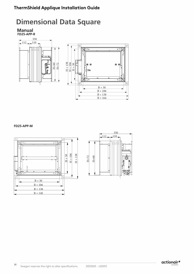
Dimensional Data SquareManualFD25-APP-R
350112 110
H+7
2H
+60
B + 30B + 106B + 138B + 164
H +
30
H +
106
H +
138
B + 30B + 106B + 138B + 140
H +
30
H +
106
H +
138
H+7
2
H+6
0
350112 110
FD25-APP-M

19 20210615 - L00012 Swegon reserves the right to alter specifications.
ThermShield Applique Installation Guide
Dimensional Data CircularManual
( n/2)+80 ( n/2)+94
380 100 45
n
n+ A
( n/2)+80 ( n/2)+94
380 100 45
n
n+ A
Ød
380100 45
Ød
+A
(Ød/2)+80 (Ød/2)+94FDC25-APP-R
45
145
380
n+160
n+ A
380
Ød
+A
Ød+16
0
100 45
Ød
FDC25-APP-M

ThermShield Applique Installation Guide
20Swegon reserves the right to alter specifications. 20210615 - L00012
Inspection and handover check sheetThis certificate applies only to Swegon Fire Dampers. The installer must complete this installation certificate when installing fire and smoke dampers. A separate certificate must be completed for each individual fire and smoke damper.
Damper Unique System I.D: ..........................................................................................................................................................
Name of installation location:......................................................................................................................................................... Address:............................................................................................................................................................................................ Installation location identification section/floor/room: ................................................................................................................ Damper product type: .................................................................................................................................................................... Release fuse temperature: .............................................................................................................................................................. Notes/Considerations: ....................................................................................................................................................................Installed by: ..................................................................................................................................................................................... Company Name: ............................................................................................................................................................................ Address: .......................................................................................................................................................................................... Company Telephone No: ............................................................................................................................................................... Installers Name: .............................................................................................................................................................................. Installers Telephone No: ................................................................................................................................................................. Date of installation: ........................................................................................................................................................................
It is hereby verified that the damper detailed above has been installed and tested according to the manufactures recom-mendations:
Installers signature: ................................................................................................ Date: ................................................
Question Action
1 Are the dampers the correct type? Confirm damper is correct type for the application
2 Are the dampers located correctly? The damper location is to be checked against the installation drawings/details
3 Are the dampers correctly identified? Unique system ID to be clearly indicated on the damper or other agreed location.
4 Have supports for both the damper and the adjacent ductwork been installed in accordance with the approved manner?
5 Are the dampers fitted in the correct orientation? Confirm the damper is installed with any actuators (if applicable) on the left or right hand side. Not on the top or the bottom (i.e. blade pivot running vertically).
6 Is access through the ductwork, to the damper unob-structed?
Unobstructed space should be provided for safe access to the damper. This must include access through ceiling voids and adjacent services. Damper installer to advise the system designer if problems are foreseen.
7 Has the space around the damper and within the opening been left clear and not been used for other services?
Other services within the installation opening will invalidate the installation method. Damper installer to advise the lead contractor if problems are foreseen.
8 Using the access opening provided, check that blades open and close.
Check position of damper blades.
9 Has the damper been checked for internal cleanliness, free from damage and that vertical casings in particular are free from debris?
With the damper in the closed position, inspect for damage.
10 Has the damper been released to simulate operation of the thermal release? (Damper drop test)
Ensure damper operation is free from interference.
11 Have the damper blades been re-set following drop test and the access panel replaced?
After re-setting the damper, check the position shown on the blade position indicator is correct.
12 At the time of damper handover, is the fire barrier and penetration seal complete?
Damper installer to record on the handover register if any following trades are still to complete their activities.
13 Is the damper installation complete and available for handover prior to system commissioning?
Obtain the relevant acceptance of the damper installation from the CDM coordinator (or equivalent).
14 Is the completed handover register cross-referenced back to the identification codes listed in the system designers damper schedule?