here - school of engineering - university of connecticut
TRANSCRIPT

For additional information or future participation contact:
Mechanical Engineering Senior Design Presentation Day 2009
Professor Thomas BarberDept. of Mechanical EngineeringUniversity of Connecticut191 Auditorium Road, Unit 3139Storrs, Connecticut 06269-3139Tel: (860) 486-5342 Fax: (860) 486-5088E-mail: [email protected]
Friday May 1, 20091:00 - 4:00 PMStudent Union BallroomUniversity of ConnecticutStorrs, CT 06269
HILLSIDE ROAD
STUDENT UNION
Parking is available in the South Parking Garage on Stadium Road (behind the UConn Coop build-ing).
South Parking Garage q q Student Union
UConn Coop q

Senior Design Project Program 2008-2009 Page 2
The UConn Senior Design Project Program (Senior Design Project Course I and II) is a hallmark of success for the Department of Mechanical En-gineering. In this two-semester course, senior students are mentored by department faculty and industry engineers as they work to solve real-life engineering problems for company sponsors. Students learn about the principles of design, how ethics affect engineering decisions, how profes-sionals communicate ideas and the day-to-day implications of intellec-tual property. In the course of a year the student teams synthesize design know-how, judgment, technical skills, analysis, creativity and innovation to design, optimize and manufacture a prototype model, or to perform product simulations.
Each Senior Design Program project meets the design criteria established by ABET, an engineering accreditation board, as a necessary component in a successful undergraduate engineering education. A mechanical engi-neering program must demonstrate that graduates have the ability to work professionally in both thermal and mechanical systems and complete the design and the realization of such systems.
Students begin by researching the problem, brainstorming a range of solu-tions, and travelling to the sponsor company site to learn more about how the company works and how the project fits in. They hold meetings, com-municate regularly with their industrial and faculty mentors, and make presentations on their work. They conduct peer design reviews, submit formal written reports and demonstrate their final solution at Senior De-sign Demonstration Day.
Senior Design Demonstration Day gives parents, friends and sponsors the chance to see projects at work, ask questions of students, and learn more about mechanical engineering at the University of Connecticut.
This May 1st the Univeristy of Connecticut Student Union Building will be filled with students, dressed to impress, explaining their projects to visi-tors, including a team of judges chosen from local engineering industries. The judges will review the projects and award first to third place cash prizes for excellence. A Professor’s Choice prize will also be awarded by faculty members to the team that most effectively applied fundamental principles to their project.
Design Demonstration Day clearly demonstrates that UConn ME engi-neers are educated to lead, create and innovate. Many seniors have been offered jobs from their company sponsor before graduation, and four pat-ents are pending from Senior Design projects completed in the last five years.
Thank you to our sponsorsOur project sponsors gener-ously support senior design. They provide the time, ex-perience, and financial sup-port that make the program possible, and in the process help our students become professionals.
We thank these sponsors and donors for their support:
AlstomASML DominionGeneral Dynamics / Electric BoatGeneral Electric Gentex Optics / EssilorGKN StructuresHabco Inc.Hamilton SundstrandHenkel Loctite OSIM Otis ElevatorPfizerPitney BowesPratt & WhitneyRBC BearingsRogers Corp. SiemonUnilever UTC PowerWestinghouse Electric Wilkinson SwordWindham Dental GroupWiremold Legrand
Army Research OfficeNational Science FoundationUConn Foundation
The Senior Design Project ProgramA Note from Professor Tom Barber, Coordinator

Senior Design Project Program 2008-2009 Page �
Message from the Department Head
Dear Students, Guests, Faculty and Staff,
I am delighted to welcome you to the annual Me-chanical Engineering Senior Design Day. This year’s event marks the 11th anniversary of our compre-hensive senior design course sequence. This year our students are showcasing 39 industrially-sponsored projects sponsored by 27 different companies and organizations. We are extremely proud of our stu-dents’ achievements and grateful for the support and engagement of many industries in Connecticut and across the nation. We strongly believe the experience gained by our students in pursuit of their senior de-sign projects enriches their UConn education and will benefit them throughout their careers. We in-vite you to explore and inquire about the projects our students will be presenting, and welcome your suggestions and feedback.
Enjoy your time and thank you for your support.
With my best wishes,
Baki M. CetegenProfessor and Department Head

Senior Design Project Program 2008-2009 Page �
Team 1: Snap Closure Design Optimization of Unilever Product BottlesSponsored by Unilever Sponsor Advisor: Joseph Everard
Project: Unilever has chosen to focus more on the snap closure technology instead of a threaded core design that is widely used on the personal care product bottles throughout the industry. The benefits of a snap on closure include faster molding times and less plastic than the previously used threaded core model. In addition, less equipment is needed to apply the snap bead cap to the bottle than the threaded core model, which results in faster and less expensive application lines. This ultimately results in economic benefits. The purpose of this design project was to optimize the current snap closure design by creating a physical model that lessened the application force necessary during the cap application process as well as one that provided more consistent and predictable application force from pack to pack. The new closure also needed to main-tain the current removal force.
A series of digital models were created using UGNX 6.0 and FEA simulated using UGNX Nastran. After a series of redesign processes and FEA tests, the final design was selected and a mold was built in Atlanta, GA. By utilizing Unilever testing methods as well as the development of a couple tests, the team documented baseline performance of the original models and validated the degree of improvement offered by the new design. The caps were molded at the Global Closure Systems Technical Center in Libertyville, Illinois, and the bottles were molded at Alpla Inc., North American Technical Center in McDonough, Georgia. Once the two were molded, line trials were run at Unilever HPC in Jefferson City, Missouri. Testing results between the current and the team’s models were compared and the final results were analyzed. Unilever was able to use the team’s model and the results generated to help improve their snap closure engagements.
Team 1: Faculty Advisor Prof. Robert Jeffers, J. Adam Lyman, Moustafa Mohamed, and Christopher Pietras

Senior Design Project Program 2008-2009 Page �
Team 2: Single Bearing Roller Element Fatigue Test MachineSponsored by RBC Bearings Inc. Sponsor Advisor: John Cowles
Project: RBC Bearings is a bearing manufacturer with facilities all over the country. Currently they are trying to enhance the performance and reduce the cost of their rolling element bearings. Industry standards are to test bearings as a whole and it is often difficult to determine the effect of changes at the component level. It would be useful to have a test machine that tests only the rolling elements of a bearing, rather than the entire bearing which includes rolling elements, cages, retainers, inner and outer rings. With this in mind RBC provided the team with a thread-rolling machine that was modified into a test rig to determine the fatigue properties of the individual rolling elements. The test rig will allow RBC to isolate the performance of the individual rolling element from the
complete bearing assembly.
The current project focuses on potential material differences between needle rollers used in pump bearings. The team prepared theoretical behavior and fatigue life expectancy of the needle roller to compare with the experimental data gathered throughout testing. The testing machine applies a compressive force on the needle roller while the roller is rotating at a constant speed in order to mimic conditions experienced in a roller bearing. The forces applied, temperature and displacement are measured while the needle roller is rotated under constant load through the use of data acquisition equipment. Data for each test is then recorded to compare behavior between roll-
ers. The testing carried out as part of this year’s project will allow comparison of material stock and heat treat from different vendors with the goal of saving cost in the manufacture of a series of roller bearings.
Team 2: Michael Schmidt and Christopher Soler (not pictured: Faculty Advisor Prof. Bi Zhang)

Senior Design Project Program 2008-2009 Page �
Team 3: Fatigue Life of IntraLock Dental Implants Sponsored by Windham Dental Group Sponsor Advisor: Dr. Dennis Flanagan, D.D.S.
Project: The purpose of this design project is to deter-mine the fatigue life of 2.1-mm titanium dental implants. The implant, which is used to replace a patient’s missing tooth, is one of the top methods to replace a tooth. Not much information however is known on how long a pa-tient can expect them to last. Due to the expense of the procedure, this is a very important factor.
The design team has built a device to test the fatigue life of these implants and measure how long they can be expected to survive. The device built applies a cyclic force on the dental implant which corresponds to the average human biting force. The team also constructed a computer model rooted in fracture mechanics that cor-responds with the physical test. Abaqus finite element analyses of the implant in similar conditions to the phys-ical test allowed the team to measure fracture mechanic properties and maximum stresses which aided in fatigue life prediction. The results of this project will enable den-tists to give patient’s realistic estimates of how long they can expect these dental implants to last, a key factor for any patient thinking of investing in such an operation.
Team 3: Shawn Cochran, Faculty Advisor Prof. Horea Ilies, and David-John Plis

Senior Design Project Program 2008-2009 Page �
Team 4: Develop Visual Inspection System for Pipe Welds under High Temperatures and Rough Environmental Conditions
Sponsored by Dominion Nuclear Connecticut, Inc.Sponsor Advisors: Michael Lalikos, Clint Gladding
Project: Dominion Nuclear Connecticut performs high quality welding of piping to support maintenance and continuous improvement changes to Millstone Nuclear Power Station. Welded joints are rigorously inspected using various surface and volumetric nondestructive testing techniques including radiography to detect defects after the joint is completed. The objective of the design project is to develop visual inspection equipment and techniques required to perform inspections of pipe welds. The inspection equipment will save Dominion Nuclear time and labor cost during weld inspections of refitted industrial piping. The inspection process will be performed after completion of the root weld while the pipe is maintained at a preheat temperature of 400°F - 600°F.
In order to overcome the temperature constraints, a thermal insulating sleeve was designed to protect existing video probe technology used by Dominion Nuclear. The thermal sleeve will insulate and cool the video probe from the 400°F - 600°F temperatures for 30 minutes. The thermal insulating sleeve design consists of an insulated composite sleeve that surrounds the video probe, and a continuous flow of argon gas to insulate against the heat-ing conditions inside the pipe. The thermal insulating sleeve was designed to fit through a 7/8” diameter access hole through the pipe wall of 18” – 30” diameter pipes, and inspect the inside diameter of the pipe root weld. During testing the design maintained the temperature of the video probe at 140°F; sufficiently below its maxi-mum operating temperature of 175°F.
Team 4: Jason Cummings and Jed Simpson Miller (not pictured: Faculty Advisor Inst. Marty Wood)

Senior Design Project Program 2008-2009 Page 8
Team 5: Analysis and Verification of Performance of Respaced Reheater Assemblies in BoilersSponsored by Alstom Power Sponsor Advisor: Dan Gelbar
Project: Alstom is a world leader in energy infrastructure, with headquarters in Levallois-Perret, France. It is currently ranked number one in the world in hydroelectric power generation, conventional nuclear islands, and environmental control systems. The boiler reheater is a tube heat exchanger that reheats the steam exhausted from the high pressure turbine before it enters the intermediate pressure turbine based on the Rankine reheat cycle. The steam in the tubes is heated by the hot combustion gases leaving the boiler furnace. Heat transfer to the tubes has been determined to be a function of the tube spacing, and is correlated by Alstom from experimental data. However, for certain tube spacings Alstom’s in-house heat transfer software has been unreliable in predicting heat transfer.
Alstom Power guarantees steam temperatures and plant efficien-cies, and is subject to large penalty clauses if the guarantees are not met. Therefore, it is of extreme importance to understand and
be able to predict heat transfer in the boiler. The Senior De-sign Group has used FLUENT computational fluid dynamics (CFD) software to analyze the heat transfer in tube bundles with various tube spacings. Using the CFD data acquired from FLUENT, the Group has offered a correction to Alstom’s data.
Team 5: Yanell Sandberg, Faculty Advisor Prof. Amir Faghri, and Tyler Paul Pelkey

Senior Design Project Program 2008-2009 Page 9
Team 6: The Telescoping Tele-Power PoleSponsored by Wiremold-LegrandSponsor Advisor: Daron Callahan
Project: Wiremold/Legrand is the manufacturer of a product known as the Tele-Power Pole, a vertical structure that safely brings power and communication wiring down from an overhead source to an isolated area. The poles are offered in standard and custom lengths from 10 to 25 feet and are often damaged during individual shipping. To reduce these shipping damages, the senior design team worked to create a product known as the Tele-Power Pole Extender. Since the product consists of small sections shorter than 9 feet, Wiremold has the option of quickly and safely shipping the poles via UPS. A complete Tele-Power Pole can rapidly be assembled by either attaching multiple Extenders together or by adding Extenders to a pre-existing pole.
The team designed the method of rigidly attaching sections together using inner sleeves and a clip. The inner sleeves are fastened to the covers of the Extenders on one end during production and smoothly slide into the receiving covers to provide the pole with lateral strength. The clip is easily attached to the divider of the receiving pole with a set screw by the installer. A hole in the clip then fits over a Wiremold-installed bolt in the Extender section to lock the sections together and provide constraint from separation. After SolidWorks models were developed, prototypes were tested to ensure adequate strength in both transverse and separation directions. Additional design considerations includ-ed devising wiring procedures and establishing optimal Extender lengths to match market demand. Upon finaliza-tion of the design, the team prepared for production by ordering tooling, devising packaging and optimizing cell layout.
Team 6: Daniel Laurinitis, Allison Daub, Faculty Advi-sor Prof. Zbigniew Bzymek, and John Dibenedetto

Senior Design Project Program 2008-2009 Page 10
Team 7: Lens Cell Thermal Survivability & StabilitySponsored by ASML Sponsor Advisors: Mike Meehan, Victor Cappelli, Fred Scipione
Project: A lens cell system consists of an optic mounted inside a lens cell. As a leader in the lithography industry, ASML uses high-precision optical systems to achieve resolutions up to 40 nm of wafer features. As a result, they must ensure that any lens systems meet specifications after the shipping process. During transportation, the sys-tems are subject to temperatures between 0 and 40°C. The lens systems must both survive the thermal cycling as well as not deform. The purpose of this project is to investigate a method to test the thermal survivability and stability of lens cell designs. Thermal deformation was measured by designing an apparatus that could detect any shift between the optic and cell positioning. Initially several design concepts were studied and compared to determine the most appropriate solution. An interferometry solution was ultimately chosen for its capability of sub-nm resolution as well as its adaptability for future testing purposes. This method uses an interferometer, holographic optical element and calibration fixture. The interferometer measures interference between beams of light to perform an optical analysis of a surface. The holographic optical element is used to transform a planar beam of light into a spherical wave front corresponding to the specific curvature of the test optic. The calibration fixture was designed to allow calibration of the interferometer using a mounted reference cell. A kinematic mount was incorporated into the calibration fixture to allow repeatable positioning of the test cell to decrease testing time. Validation test-ing of the design has been done by taking initial measurements of the test cell surface using the interferometer. The lens system was taken out of the apparatus, thermally cycled between 0 and 40°C and then placed back into the apparatus. Any deformation was then detected by comparison of the two sets of data.
Team 7: Peter Kutrumbos, Danny Lee, and Faculty Advisor Prof. Thomas Barber

Senior Design Project Program 2008-2009 Page 11
Team 8: Coolant Side Flow Distribution within the Multi-Fluid EvaporatorSponsored by Hamilton Sundstrand Sponsor Advisors: Gregory Quinn, Mark Zaffetti
Project: Hamilton Sundstrand has designed a Multi-Fluid Evaporator for the Orion Space Project as a second-ary heat rejection system during times of elevated heat rejection needs. The evaporator uses alternating layers of coolant and evaporant flowing across a quarter-circle configuration. In both cases, the fluid is distributed evenly using radiator fins. Unfortunately, during early testing, engineers noticed water carry-over along the outer edges of the device, which indicates that not all of the evaporant is evaporating. It was speculated that the flow in the coolant layer was experiencing mal-distribution, which would cause uneven heat transfer to the evaporant layer. To investigate this, the coolant layer was modelled using FLUENT, a Computational Fluid Dynamics Software package. The fins were modelled using porosities in the radial and axial directions that were found experimentally by testing the pressure drops in those respective directions. In addition to the FLUENT model, a full-scale physi-cal model of the coolant layer was constructed using Plexiglas, and trials were run to examine the flow distribution using a pulsing dye injection and a hydrogen bubble visualization setup. Once the flow distribution was analyzed, different fin configurations were tested to create a more uniform flow distribution.
Team 8: Logan Bass, Michael Anderson, and Faculty Advisor Prof. Baki Cetegen

Senior Design Project Program 2008-2009 Page 12
Team 9: Reducing Tablet Coating Process Cycle TimeSponsored by Pfizer Sponsor Advisors: Daniel Blackwood, Bruce Cathcart
Project: Pfizer is the world’s largest research based pharmaceutical company. The project presented by Pfizer involves the manufacturing of the various medicines they develop in tablet form. When the tablets are made, they are coated for a wide variety of purposes. This coating can be used to block light from reaching the active ingredient, improve the strength of the pill, help keep moisture from the active ingredient or give the tablet different colors to help distinguish tablets of different dosages. The coating is an aqueous liquid that is sprayed on the tablets while they are tumbled in a dryer-like pan. In order for the coating to adhere to the tablets, they must be kept at a certain temperature. This temperature is generally around 100°F. Once the coating solution has been applied the tablets are left to cool back to room temperature. In the current process the tablets are inserted into the coating machine before they are heated and stay in the machine while they cool down.
The objective of this project was to create a method/device to allow the heating/cooling to be applied outside of the coating machine so that the tablets have less downtime and the coating machine spends more time applying the solution. The team explored various methods in search of a solution. They looked at systems that did the job continuously and ones that did it in a batch. After several design modifications, the team settled on a batch process to heat the tablets to the desired temperature and then feed them into the coating
machine. Once the coating machine has applied the coating solution, the tablets are ejected from the machine and back into the team’s device. The tablets are then cooled down to room temperature in the device while the coating machine starts
the solution application on another, already heated, batch of tablets.
Team 9: Thomas Paquin, Joseph Wilson, Nathan Fox, and Faculty Advisor Bi Zhang

Senior Design Project Program 2008-2009 Page 1�
Team 10: Tire Inflation Safety Cage for a Chinook Helicopter Sponsored by Habco Sponsor Advisor: Vinay Patel
Project: HABCO, located in Glastonbury Connecticut, is an engineering firm mostly known for providing ground support and testing equipment to the United States armed forces, commercial aerospace manufacturers, industrial and power generation providers, and medical device manufacturers. A product currently offered by HABCO is the Black Hawk tire inflation safety cage used while inflating a Black Hawk helicopter tire to contain any poten-tially harmful debris in the event of an explosion. This year’s senior design team was asked to develop a similar tire inflation safety cage to be used on the CH-47 Chinook helicopter. The project’s objective was to design the cage to enclose the Chinook’s complex wheel assembly while the tires are being inflated.
A SolidWorks model of the cage was developed and thus modified in accordance with the suggestions by Hawk, one of HABCO’s major clients; these changes allowed better maneuverability on rough terrain and accommo-dated for preferences of the servicemen performing the tire inflation. First priority being safety, the cage must be extremely rigid and reliable thus ensuring it would not fail under the extreme forces of the explosion. Finite Ele-ment Analyses were undertaken by the team, where the cage’s performance was analyzed by a worst case scenario of the forces encountered in a tire explosion. Upon finalization of the design, the team completed the manufac-
turing process by creating a bill of materials and welding plan for the prototype. The cage was then professionally assembled under supervision of the team.
Team 10: Matthew Dietrich, Faculty Advisor Prof. Kevin Murphy, Thomas Kirstein, and Robert Khalil

Senior Design Project Program 2008-2009 Page 1�
Project: Rogers Corporation, a manufacturer of high-performance specialty material products, has a lamination machine which produces striations in their coatings. The design team’s task was to eliminate the striations from future laminations. The first point of action was to determine the cause of the marks. Several different causation theories were developed, including vibration transmission, fluid instabilities and belt slip. The team has done extensive research on various transmission devices (V-belt and toothbelt drives), and gathered data from numer-ous lamination machine experiments. In these experiments run conditions were varied while data was collected from different locations on the laminating machine. The first method that was investigated was the vibration transmission theory. Data was collected from several points of interest along the machine using accelerometers. While analyzing the data, the team brainstormed an assortment of vibration isolation methods (viscoelastic damp-
ing, a tuned absorber, or other active vibration isolation techniques). The team was to choose the best method to eliminate the vibrations when their source was located.
However, the data collected was continually inconclusive, so Rogers Corp. decided to replace the original gearbox with one that has a single reducer internally to de-velop less noise. The striations in the lamination were then eliminated. The team then began to look into ideas related to roller slippage and how it might cause imperfections in other laminations. A guide was developed describing different roller measurement techniques and the development of various technologies. The team finalized a design of a coating roll drive system which minimizes the induced mechanical noise and created a model using Unigraphics NX.
Team 11: Ramin Rafatpanah, Faculty Advisor Prof. Eric Jordan, and Karen Talamo
Team 11: Coating Roll Vibration Analysis Sponsored by Rogers Corp. Sponsor Advisors: Chad Waddell

Senior Design Project Program 2008-2009 Page 1�
Team 12: Blade Breaking StudySponsored by Schick-Wilkinson SwordSponsor Advisor: David Noble
Project: Schick-Wilkinson Sword is a manufacturer of personal safety razors. A key process in the manufacture of razor blades is the removal of the sharpened edge from the bulk of the body of the blade. This is a breaking process performed at high speed to produce brittle fracture of the strip. Typically, a linear portion of the strip is weakened mechanically to encourage consistent breaks at the right location. The purpose of this project was to analyze the physical properties of blade breaking. A step in the current process of manufacturing razorblades may potentially cause ill effects by causing the microstructure to change and hinder the performance of the blades.
Schick-Wilkinson Sword has asked this team to test forces required to break the razor blades in multiple direc-tions. The experimental portion of breaking the blades was accomplished by means of an Instron, which recorded the force vs. extension of the breaking process. The holding tools that attach to the Instron have been specifically designed by the team. Since multiple variables in the experiment were changed, in order to compare the tests, two holding fixtures were designed to hold the blades during breaking; one fixture was designed for shearing of the blade and the other for cutting. Next the data recorded by the Instron was analyzed and compared to other tests in the experiment where multiple variables of the experiment have been changed. The broken blades were then inspected under a Scanning Electron Microscope, with varying degrees of magnification. With visual imagery, the team could see how breaking the blades affect the microstructure of the razor blade steel. Finite element analyses (FEA) were also conducted. With each change in testing variables, the force-extension curves recorded by the In-stron changed considerably. With this data, stress-strain curves were created and modulus of elasticity of the steel was estimated. This data along with the force-extension curves gave the company a better understanding of the
physical properties of the blades.
Team 12: Daniel Giedra, Faculty Advisor Prof. Robert Jeffers, Brian Swatkins, and Benjamin Carignan

Senior Design Project Program 2008-2009 Page 1�
Team 13: Scoping Containment Analysis for the Westinghouse Large Passive PlantSponsored by Westinghouse NuclearSponsor Advisors: Charles Kling, Richard Ofstun
Project: Westinghouse Nuclear is a company that provides fuel, services, technology, plant design, and equip-ment for the commercial nuclear electric power industry. Currently Westinghouse has a very successful plant design on the market, the AP1000, which generates approximately 1000 MW of electricity. Yet as demands for clean energy increase, Westinghouse is planning to increase the power output of their AP series power plants. Senior Design Team 13 focused on the containment design for a larger passive plant. The team was charged with the task of modeling and analyzing a proposed next generation containment structure and its safety features, blowdown pressure suppression and passive cooling, with the intention of developing empiri-cal relationships between various design parameters. All of the analysis was done using GOTHIC (Generation of Thermal-Hydraulic Information for Containment), an application created by Numerical Applications Inc. The large passive plant was modeled in GOTHIC and subjected to multiple steam line/coolant breaks to see if the design could handle the mass and energy releases during these accidents. A scoping study was performed and, in the end, a set of empirical parametric relationships were developed by the team to be used by West-inghouse to aid in the design of their next generation reactor.
Team 13: Faculty Advisor Prof. Wilson Chiu, Phillip Carlu, and Jordan Penley

Senior Design Project Program 2008-2009 Page 1�
Team 14: Improving Hot Strength Testing Fixture DesignSponsored by Henkel LoctiteSponsor Advisors: Pat Courtney
Project: Loctite, a division of the German owned Henkel Company, produces and sells over 800 different types of adhesives that must be tested under many different environmental conditions in order to guarantee that the product performs as advertised. One such procedure is the Hot Strength test, where bonded samples are tested for tensile strength in an oven at up to 300°F. When using the existing fixture, torsional loads are applied to the bonded sample while it is being loaded into the test fixture, causing variance in test results. Variance in test results is improved by eliminating torsional loading of the sample through a redesign of the test fixture and test procedure.
Team 14: Michael Bifulco, Andrew Breault, and Faculty Advisor Prof. Tai-Hsi Fan

Senior Design Project Program 2008-2009 Page 18
Team 15: Improving Process / System Design for Fixture Testing of CyanoacrylatesSponsored by Henkel LoctiteSponsor Advisor: Pat Courtney
Project: Cyanoacrylates adhesives or Superglues are widely used and derive much of their value from their ability to rapidly develop bond strength (fixture). Loctite adhesives division of Henkel Corporation routinely performs a fixture test for the cyanoacrylate adhesives produced, which measures the amount of time required for the bond to reach a certain shear strength. Current testing methods rely largely on operator experience to reduce error,
and thus wide fluctuations in fixture time can be seen. The project goal was to reduce the error in testing. The team chose to ap-proach the problem by isolating potential sources of error, and testing each source to verify or disprove their effect. A prototype testing device was drafted based on data from experimentation. Identical tests were then conducted again to demonstrate an improvement in standard deviation of test results. An improved testing procedure re-sults in tighter quality control, easier com-parison of new products, and higher cus-tomer satisfaction.
Team 15: Michael Johnson, Faculty Advisor Prof. Brice Cassenti, and Jim Sun

Senior Design Project Program 2008-2009 Page 19
Team 16: Experimental Method for High Rate Water Impact Loading of Composite Laminates
Sponsored by Electric Boat Sponsor Advisors: David Hufner, Bob Groner, Matthew Augustine
Project: Electric Boat (EB), the world’s leading design and manufacturer of nuclear submarines, proposed a design project for testing composite laminates under a dynamic, impulsive pressure force. Composite material behavior is generally well understood in the linear regime, and can be predicted with sufficient confidence up to the point of first ply failure. However, the mechanical behavior beyond first ply failure is more difficult to characterize due to material nonlinearity, strain rate dependence, and progressive failure. Use of composite materials often requires that dynamic material behavior be fully characterized. The design team was to create a cost effective test method to help characterize the behavior of an E-glass/Vinyl ester composite laminate plate. Because of the popular use of composite laminates in the naval field, previous test methods exist and were researched by the design team. This project has adopted previous ideas and has improved the validity of the system parameters. Initially, FEA modeling was completed to determine the energy requirements needed to obtain the project goals. Using those results, a pneumatic system was developed and tested numerous times, with the results within the initial project goals. The pneumatic actuator was used to strike a piston which rests atop a water column. The contact between the striker and piston creates an impulsive pressure wave traveling through the water, deforming the composite specimen at the bottom. The design team successfully created an inexpensive fixture to determine the dynamic material characterizations of composite laminates.
Team 16: Faculty Advisor Prof. Eric Jordan, Brian Anderson, and Christopher Howard
y = -1E-09x2 + 1E-05x + 0.0014R² = 0.9614
0.000%
0.500%
1.000%
1.500%
2.000%
2.500%
3.000%
0 500 1000 1500 2000 2500 3000 3500 4000 4500
Stra
in
Pressure (psi)
y = -1E-09x2 + 1E-05x + 0.0014R² = 0.9614
0.000%
0.500%
1.000%
1.500%
2.000%
2.500%
3.000%
0 500 1000 1500 2000 2500 3000 3500 4000 4500
Stra
in
Pressure (psi)

Senior Design Project Program 2008-2009 Page 20
Project: In an effort to improve manufacturing cycle time and quality of polycarbonate optical lenses, Gentex Optics has begun an initiative to analyze the three dimensional transient heat transfer within its injection mold-ing manufacturing process. The main aim of this project was to estimate the various heat transfer coefficients throughout the solid contact interfaces and cooling pipes inside the mold and then apply them into an ANSYS transient thermal simulation for analysis.
A number of one-dimensional quasi-steady state analyses were developed in order to obtain an understanding of the mold heat transfer. Literature research was conducted to find contact correlations and gap contact conductance throughout the mold con-
tact interfaces. A one-dimensional steady state heat transfer experiment was also designed in order to experimentally determine the contact con-ductance to compare to values in literature. Two rectangular, metallic blocks with the same surface finish as the actual mold surfaces were pressed together at max pressure of 10,000 psi, while heat transfer was created through the mating surfaces. Thermocouples inside the blocks measured the temperature drop and heat flux across the contact faces to calculate the contact conductance. Correlations from literature were used to estimate the convection heat transfer coefficients throughout the mold’s water cooling channel. Transient thermal simulations were performed with ANSYS finite element solver using the estimated heat
transfer coefficients. Tem-perature distributions and heat fluxes were observed to understand the main driving forces or hindrances to heat transfer. In the future, these ANSYS cooling simulation results will aid Gentex Optics in evaluating the current mold performance and will assist in future design improvements.
Team 17: Faculty Advisor Prof. Wilson Chiu, Tri Nguyen, and San Kim Quach
Team 17: Determination of Heat Transfer Coefficients for Design and Optimization of the Ophthalmic Molding Process
Sponsored by Gentex Optics/Essilor Sponsor Advisors: Eric Begg
)/ln(2
12 rrkLhA p
=

Senior Design Project Program 2008-2009 Page 21
Team 18: Validation of FLUENT for Predicting Flow & Heat Transfer Characteristics of Pedestal Arrays
Sponsored by Pratt &WhitneySponsor Advisors: Atul Kohli, Stephanie Santoro
Project: In order to adequately cool the blades inside the turbine section of a modern turbojet engine, Pratt & Whitney uses internal cooling flows; channels inside each blade through which air from colder sections of the engine is pumped. In the case of this senior design project, the trailing edge channel exit was the area in question. Here the cooling flow passes through a pedestal (pin fin) array before exiting back into the main engine flow. The fluid flow and heat transfer parameters associated with these channels have historically been predicted through the use of correlations, obtained through laboratory experiments. While adequately predicting the cooling performance, the range of applicability is limited, only really useful for the geometric
configurations tested in those laboratory experiments. In this senior design project it has been shown that the performance described in the experimental laboratory tests can be accurately predicted through the use of computational fluid dynamic (CFD) numerical simulation using FLUENT. The relatively inexpensive cost of a CFD simulation when compared to a large and expensive laboratory experiments allows engineers to design and evaluate the perfor-mance of many pedestal arrays to find the best option for the particular task at
hand, ultimately reducing the cost of design and increasing cooling performance.
Team 18: Graham Philbrick, Daniel Gindraux, and Faculty Advisor Prof. Thomas Barber

Senior Design Project Program 2008-2009 Page 22
Project: Pratt & Whitney is one of the leading aircraft engine manufacturers in the world. The F135 turbo fan en-gine from P&W is the engine of choice for the F35 Joint Strike Fighter (JSF) from Lockheed Martin. The fighter jet uses a 3 bearing swivel duct (3BSD) to control thrust vectoring, which allows the aircraft to takeoff vertically or in short distances. The current manufacturing process of the 3BSD is complex and lacks performance in effi-ciency and ergonomics. This project developed a new lean manufacturing system that will help increase efficiency and ergonomics while reducing waste and military production costs. The lean manufacturing principles work in conjunction with P&W Achieving Competitive Excellence (ACE) tools and their proprietary DIVE Process.
The first component of the new production process included designing and implementing flexible tooling and fixtures that simplify material handling and are used throughout the entire process. The fixture is responsible for physically handling the part in space. Flexibility means that the fixture can be used in different stages throughout production without having to dismount or reset the part until the manufacturing process is complete. A compos-ite box protects the part when not held by the transport fixture. The second element of the project was to design a method for horizontally assembling the F135 nozzle. Currently the engine is assembled vertically, using gravity to lower the 3BSD liners into an outer case. This method requires multiple operators and induces several safety hazards. Loading these parts horizontally will help eliminate assembly issues and simultaneously pace the process. By completing the design of the fixturing, tooling, and horizontal assembly process, this project has successfully increased the efficiency of the F135 engine production.
Team 19: F135 Lean Manufacturing Tooling and Masking
Sponsored by Pratt & WhitneySponsor Advisor: Michael J. Schober Team 19: Faculty Advisor Prof. Robert Gao, Faculty Advisor
Prof. Nejat Olgac, Hadrian Kim, Greg Hosselbarth, and John Darash

Senior Design Project Program 2008-2009 Page 2�
Project: Pratt & Whitney creates high quality and dependable combustion engines for the commercial and mili-tary industries. As a leader in manufacturing jet engines, each piece of the engine is designed and produced under the highest of standards. Every system in the engine has its own experts in the field, one being the Compressor Sys-tems Module Center. Their task is to design and optimize the compressor section to create the lightest, strongest, most efficient, and safest compressor system possible. This is a main component of any jet engine, and the best situation is to optimize all the parameters with the least amount of assets consumed by the company. This means ideally to use a computer to automatically calculate the optimized parameters which can include temperature, material, geometry, and more.
The goal of Team 20 was to create the start of a Windows based optimization tool for the cross-sectional geometry of a low pressure compressor disk in jet engines. It is necessary to reduce the disk’s weight, while keeping the hoop stresses in the material’s allowable and safe range. This will keep the engine’s weight low, while instilling Pratt and Whitney’s goal of dependable engines. The team mimicked P&W’s current in-house program, but transferred it to an up-to-date Windows version using MATLAB, instead of the existing program which is based in UNIX. The
program takes in the geometric, material, and other environmental parameters, and calculates the weight and internal average stresses in the disk. The team’s tool has been validated by the FEA program AN-SYS with 2-D and 3-D analysis. P&W’s in-house tool also optimizes the geometry, and the team has started an initial investigation of how
to accomplish this in MATLAB. This useful tool will re-duce time and in-crease the quality of any low com-pressor disk.
Team 20: Faculty Advisor Prof. Horea Ilies, Caitlin Curtis, and Evan Lehr
Team 20: Development and Implementation of Outer Electrode Design
Sponsored by Pratt & WhitneySponsor Advisor: Wendy Zhang
1
MN
MX
X
Y
Z
30794
3460638417
4222946041
4985353664
5747661288
65100
FEB 19 200916:37:21
NODAL SOLUTION
SUB =1TIME=1SY (AVG)RSYS=1DMX =.016291SMN =30794SMX =65100

Senior Design Project Program 2008-2009 Page 2�
Team 21: Product Packaging and Handling Standard WorkSponsored by Pratt & WhitneySponsor Advisor: Monique Dumais
Project: The demand for a clean source of renewable energy is increasing with the growth of social awareness and the desire to preserve the environment. Numerous companies have been focus-ing on designing such an energy conversion device as an alternate source of energy. For over 40 years, UTC Power, located in South Windsor, CT has been developing and manufacturing fuel cells for various applications. The objective of this team is to develop an alternate external manifold retention system for fuel cell stack assemblies. Material testing of cable, roller chain, and Kevlar strap-ping was completed. The best design was based on cost, flexibility, strength-to-weight, and friction reduction. The team selected mul-tiple designs to prototype, which work on the concept of unifying the tensioning process to reduce assembly time. Pressure distri-bution tests were performed using pressure sensitive film to show which design provided the best results compared to the current cable-only system.
Team 21: Faculty Advisor Prof. Thomas Barber, Mark Scarzella, and Stephen Stagon

Senior Design Project Program 2008-2009 Page 2�
Team 22: Molecular Structure as Massage Sponsored by OSIM Sponsor Advisors: James Wong, Kia Tong Tan
Project: OSIM is a worldwide leader in healthy living and massage products. Based in Singapore, OSIM has been providing consumers with quality products that promote a healthy lifestyle and personal comfort. One of the specialties of OSIM is electric massage. The field of electric massage is not a very diverse one. Most massage chairs on the market provide an intense massage that is uncomfortable or even painful for many users. This experience is caused by the rolling/kneading massage mechanism that is standard in most massage chairs. There is clearly a market for a new kind of electric massage that is more pleasurable to the user. With such a product, the consumer base for the electric massage industry could be greatly broadened. The objective of this design project is to provide an alternative to the electric massage chairs available today.
Utilizing a design inspired by a molecular model like one found in a high school science class, a more relaxing and soothing massage mechanism has been developed. Sixteen rollers on two flexible brackets contact the user and oscillate as they move up and down the back and shoulders. The mechanism is powered by a single DC motor that provides both the oscillation and the vertical motion. The flexibility in the device allows the contact points
to conform to the contours of the user’s body, providing an in-vigorating and comfortable massage experience.
Team 22: Ronald Ciak, Faculty Advisor Prof. Kazem Kazerounian, and Sean Rogers

Senior Design Project Program 2008-2009 Page 2�
Team 23: Design of an Array of Massage HeadsSponsored by OSIMSponsor Advisors: James Wong, Kia Tong Tan
Project: OSIM is a global leader in branded healthy lifestyle products. Listed in the Singapore Stock Exchange, OSIM has over 25 years of experience and uncompromising dedication in developing innovative and reliable healthy lifestyle products. The main problem being investigated in this project is the implementation of a new massage head array into an OSIM massage chair. The idea behind this new massage head array is to create a more natural sensation compared to the current rollers that are used. The team considered problems such as contact material, surface friction, and array size. Throughout the semester, the team spent time researching the current design and creating preliminary designs for implementation into the three-piston design. The three-piston de-
sign is meant to mimic the motions of a professional Massage Therapist. When all cylinders are at the zero position, the outer cylinder will be the only one contacting the user. The two inner cylinders oscillate to create massaging motions. Through testing, the group decided on a final massage array to bring into production. The heads have been designed to provide for easy in-stallation and manipulation within the chair. Having a design where the heads can be easily removed, the team was able to create different mas-sage heads that the user can change to accommodate their taste. The mechanism is powered by three DC motors and one AC motor; the team created a program that controls the motors to simulate massages such as
kneading, tapping, rolling, and Swedish massages.
Team 23: Claudio Marques, Faculty Advisor Prof. Kazem Kazerounian, and Erik Sandgren

Senior Design Project Program 2008-2009 Page 2�
Team 24: Retractable Foot Rest Massage SystemSponsored by OSIM International Ltd.Sponsor Advisors: James Wong, Kia Tong Tan
Project: This OSIM Co. sponsored design project encompassed a full design and prototype of a completely new retractable leg rest system for massage chairs. While massage chairs come in many shapes and sizes with different fit and functions, OSIM requested a massage chair that incorporated a fully functional and retractable leg massage system. This mechanism, contained underneath the chair, has the capability to position to a fully extended posi-tion out of the chair, as well as rotate in the reclined position, all interfaced with one motor. This motion is pos-sible through a drive system connected to foot and calf massage units that provide complete control for the user. The user interface consists of a two-way switch, enabling the user to extend and retract the footrest. The AC motor drives a ball & screw nut which drives two “L- Arms” attached to the back of the leg rest. The L- Arms push and pull the leg rest forward and backward as desired. The leg and calf rest are two separate entities, connected by a pinion on a designed track which disengages in the extended position. In this extended position the calf and leg rest are connected by two extrusions, allowing rigidity throughout the reclining motion. The system traverses with two degrees of freedom to reduce the possibility of jamming as well as reducing costs in production.
Team 24: Anil Karunanidhi, Michael Townsend, and Faculty Advisor Prof. Kazem Kazerounian

Senior Design Project Program 2008-2009 Page 28
Project: Headquartered in Stamford, CT, Pitney Bowes is the world’s leading technology company in mail stream solutions. The DI950 is one of the mid-speed mailing insertion systems manufactured by Pitney Bowes. The DI950 folds, collates and inserts various types of media into envelopes at a rate of up to 5400 mailings per hour. A key mechanism of the machine is located in the Flapper – Inserter sub assembly. This section of the machine opens the flap of the envelope and prepares it for the inserts. It was noted that certain envelope types caused failure in this area of the machine. Pitney Bowes mandates that the machine be able to handle a wide range of media.
Team 25 first performed experiments to identify the reasons for high failure rates of the machine during flapping. The failure rate was dependent on the type of envelope used – with the #10 brown Kraft envelope producing the highest failure rate in the flapping area. As the machine is running, the driving rollers operate at varying speeds and sometimes idle in between as well. These varying speeds cause the envelopes to travel faster or slower and deliver varying forces on impact. Since the #10 brown Kraft envelope is of a stiffer material, when it travels at a
higher speed it tends to cause a greater deflection of spring loaded rollers (secondary rollers) in the machine that are driven by the main rollers. Through experimentation, it was noted that when the envelope impacts at higher speeds and at a near 90 degree angle to the secondary rollers, the rollers then displace beyond a critical point and cause jams.
A kinematic model of the Roller – Flapper assembly was then established using Matlab to simulate the path of an envelope through the system. The model was validated with the experimental data. The geometry of the envelope’s path was modified through the addition of a guide fixture in the mechanism. The fixture incorporates a guide that redirects the path of the envelope and minimizes jams in the mechanism due to stubbing. The model was used to optimize the profile of the guide.
Team 25: Kelly Tousignant, Wendy Naples, Edward Horn, and Faculty Advisor Prof. Jiong Tang
Team 25: Flapping Mechanism Redesign Sponsored by Pitney Bowes Sponsor Advisors: Norm Lilly, Jim Salomon
C
B
A
C
B
A

Senior Design Project Program 2008-2009 Page 29
Team 26: Fuel Cell Pressure Plate Optimization
Sponsored by UTC Power Sponsor Advisor: Don Jacques
Project: UTC Power is one of the leading companies in developing and producing fuel cells for on-site power, transportation, space and defense applications, as well as renewable energy solutions. The goal of this project was to optimize the PC50 pressure plate to minimize cost of the production. Pressure plates are structural components that are located at both ends of a fuel cell stack. They are necessary to compress the cells that make up the stack and to support it. The pressure plates must distribute the load evenly across the stack while sealing it properly.
The pressure plate was redesigned to optimize its volume, weight and geometry using Finite Element Analysis. The pressure plate was assembled using mild steel c-beams and I-beams that were machined to meet the right dimensions, then welded and bolted together. To validate the FEA analysis on the redesigned pressure plate,
the stress was calculated by strain gages placed on the stress concentrations. The plate’s ability to distribute the pressure evenly across the stack was also evaluated.
Team 26: Leemor Bushari, Jonathan Ingram, Justin Gouveia, Sponsor Don Jacques, and Faculty Advisor Prof. Ugur Pasaogullari

Senior Design Project Program 2008-2009 Page �0
Team 27: Next Generation Current InterrupterSponsored by GE Consumer & IndustrialSponsor Advisor: Tom Papallo
Project: Circuit breakers are traditionally designed with one stationary and one rotating electrical contact that make and break connections. New standards in the electrical distribution industry have led to the need for bet-ter current interrupting equipment. In general, faster current interruption is required. The team has developed a current limiting circuit interrupter that uses a unique opening motion and new arc absorption techniques. The
system responds to a short circuit within 5 milliseconds and restricts the peak let-thru current to about 3kA. The movement is initiated by the magnetic constriction forces associated with adjoining elec-trical contacts. The device deviates from traditional designs by uti-lizing axial motion to separate the contacts. The concept also uses the latest in ablative techniques to open and extinguish the arc. It was prototyped, tested, and analyzed against current UL standards for circuit breakers in order to evaluate the performance of the de-sign and provide feedback to the sponsor.
Team 27: William Maurer, Bryan Marazzi, and Faculty Advisor Prof. Jiong Tang

Senior Design Project Program 2008-2009 Page �1
Project: GKN Structures, Inc. makes advanced composite components for aerospace applications. GKN utilizes resin transfer molding techniques to produce composite aircraft parts through the use of Resin Transfer Molding (RTM). In this process, the two halves of a mold are pinned together, after which the molding material, a compos-ite resin, is injected at high temperatures. Many high performance aerospace components are currently manufac-tured using Bismaleimide resins and carbon fiber reinforcements. This thermo-set resin system requires significant processing time (6 hours) at high temperatures (375°F) within expensive molding to cure. GKN Structures has a desire to reduce time, cost, tooling and energy by reducing the current cure cycle. The goal was to optimize the
resin manufacturer’s cure cycle for the Resin Transfer Molding pro-cess while maintaining equivalent glass transition temperature and mechanical properties currently achieved. The recommended cure cycle was divided into 3 abbreviated cure intervals. Glass transition temperature testing was done on neat resin samples to substantiate the abbreviated cure cycles. Next flat panels were fabricated using the current and abbreviated cure cycles. Testing on the panels was done to characterize the extent of cure and validate mechanical property equivalence. Thermal analysis was used to characterize the “green strength” of the composite material at the abbreviated cycles prior to post cure. This gave a measure of whether or not the part would hold geometric and dimensional properties as it was demolded from the cure tool and during a free standing post cure. The mechanical properties after post cure determined if the post cure interval should be modified for the new cure interval to maintain structural equivalence.
Team 28: Faculty Advisor Prof. Brice Cassenti, Justin Mackey, and Craig John Pratt II
Team 28: Structural Character-ization of Abbreviated Cure Cycles for Bismaleimide (BMI) Resin in Carbon Fiber CompositesSponsored by GKN StructuresSponsor Advisors: Steve Hayse, Susan St. Germain

Senior Design Project Program 2008-2009 Page �2
Project: ASML is the world leader in lithographic systems. ASML lithographic technology is used in construct-ing Integrated Circuits (ICs) on silicon wafers, which are becoming smaller and faster while also consuming less power. However, this optimization is only possible through the ever increasing resolution made possible by high quality optics in modern Lithographic equipment. High energy plasma ions, created from the intense light source used in a lithographic process, are constantly colliding with the illumination and collector optics. Through con-stant collisions, the lifetime of these optics are diminished as the quality of the image and resolution are affected. To combat these damaging collisions, the atmosphere surrounding the optics must be purified. This purged area helps to diminish the frequency of collisions and extend the lifetime of the collector optics by reducing the energy of these ions. ASML uses Extremely Clean Dry Air to create a Micro-Environment that maintains this air purity. However, the gas itself is also expensive and is rapidly vacating the Micro-Environment.
In ASML’s newly developed lithographic system, the XT-4, the flow resistance of the gas in a channel between the Fixed Position Plate and the Reticle Stage are not meeting the specifications set by its predecessor, the XT-3, which incorporates an additional plate. Therefore, the goal of this project is to increase flow resistance by optimizing the fluid flow, gap height, and surface geometry of the single plate present in the XT-4 using Computational Fluid
Dynamics (CFD) analyses. The team focused on altering the surface geometry to achieve increased pressure drag by incorporating a grooved geometry into the channel flow. The parameters of these grooves, height, width, and rib width were then optimized through multiple simulations. After a study analysis of the grooves in a simple channel, the team expanded into radial flow, to best duplicate the real life pa-rameters between the Fixed Position Plate and the Reticle Stage. The
resulting groove ge-ometry increases the flow resistance in order to minimize the amount of gas required in the purg-ing process.
Team 29: Lawrence Lewis III, Faculty Advisor Prof. Amir Faghri, and Jonathan Bashar
Team 29: Lens Purge Parameter Study Sponsored by ASMLSponsor Advisors: Steve Roux, Herman Vogel

Senior Design Project Program 2008-2009 Page ��
Project: ASML is a leader in the production of photolithographic equipment for microchip production. Their in-novative technologies have pushed the industry to the forefront of science for 25 years. Today, ASML is yet again planning for the future and the new generation of highly accurate machines and processes. One of the biggest challenges ASML faces is dust particle contamination. Dust particles, which could be many magnitudes larger than the microchip features, pose a threat to lithography and clean room equipment. The particles are fairly harm-less when they are settled on non vital surfaces, however they can settle on any essential component like optical lenses if are allowed to become airborne.
This project developed measurement techniques for studying behavior of dust particles in the 1 to 100µm range in low vacuum flows with surface adhesion properties. A low pressure test flow chamber capable of achieving 500 Pa was built, and was used to generate flows over the particles of known size. The relationship between particle size, shape, and surface area all play a critical role in defining its adherence to a surface. Therefore particles were
not only classified by size during tri-als, but by their respective geometries as well. The obtained data would al-low engineers to design equipment capable of suppressing dust distur-bance by maintaining flows below calculated levels.
Team 30: Pilar Vivar, Marat Kulakhmetov, Dmitry Arslanov, and Faculty Advisor Prof. Mike Renfro
Team 30: Micron Particle Behavior in Low Pressure EnvironmentsSponsored by ASML Sponsor Advisor: Steve Roux, Herman Vogel

Senior Design Project Program 2008-2009 Page ��
Project: The Siemon Company design team goal is to develop a next generation modular furniture adapter. Siemon’s current product line of modular furniture adapters consists of several different versions and part numbers due to the wide range of data port cut-outs in modular furniture on the market today. Their goal was to cut that entire product line down to one single connector that would be universally adaptable to as many
different openings as possible. The design team helped Siemon acquire sample parts from modular furniture manufactures that had been selected as most important, and used these samples to create a set of specifications that the next generation modular furniture adapter needed to meet.
Several design ideas were put forth by the team, and cooperation between engineers at the Siemon Company and the students has led to a design that is durable, adjustable, and strong. The de-sign has been refined using COSMOS finite element analyses. A working prototype of the connector has been developed and a production plan proposed which the Siemon Company can fol-low when they wish to begin manufacturing the new connectors.
Team 31: Robert Hegarty, Laura Weismantel, and William Baer (not pictured: Faculty Advisor Instr. Marty Wood)
Team 31: Next Generation Modular Furniture AdapterSponsored by the Siemon Company Sponsor Advisor: Randy Bielow, Bryan Boemmels

Senior Design Project Program 2008-2009 Page ��
Project: The Otis Elevator Company sponsored the project to test their elevator safety systems. The team’s project was to design and fabricate a test rig which accurately models and measures the dynamic pull through force over their governors. The dynamic pull through force, DPTF, is the force due to friction that occurs as a rope is pulled over a sheave. The result of this force is a difference in rope tension on either side of a sheave which was measured using tensile load cells. The rig provides Otis with a better means of testing DPTF for different variable configura-tions. It is a substantial improvement over the current method that requires the use of a full elevator hoist way. It will reduce the time and cost of DPTF testing. It also provides more focused test results by isolating the governor system during testing. The team has used the rig to test certain variable configurations that are of greatest interest to Otis. The results of these experiments have given Otis insight into the effects of input variables and variable interactions on DPTF.
Team 32: Joseph Burns, Faculty Advisor Prof. Kevin Murphy, and Michael Voket
Team 32: Dynamic Pull Through Force (DPTF) Test Rig – DOE/Testing & Rig Improvement Sponsored by Otis ElevatorSponsor Advisor: Dave Lanesey, Randy Dube

Senior Design Project Program 2008-2009 Page ��
Project: Otis has developed a new elevator system known as the Gen2 system. This revolutionary system makes use of a coated steel belt in place of the conventional braided steel belt used to suspend an elevator car. The coefficient of friction between the elevator sheave and coated steel belt is a critical parameter to measure due to the fact that the elevator is driven up and down the shaft by the contact friction between the belt and sheave. To date, Otis has
developed methods for finding the coefficient in a laboratory setting, yet the need exists to develop a tool that can be used to find this coefficient while in the field on installed belts.
The team of designers has come up with a portable device to fulfill this need. The device uses an electric actuator, rigid metal frame, and spring to find both the coefficients of dynamic and static friction. With the use of load cells and a handheld data acquisition system, these coefficients can easily be found. This device has performed within the expected 10% error margin when compared to measurements taken with the existing laboratory equipment.
Team 33: Craig Oakley, Prudencio Olmos, and Faculty Advisor Prof. John Bennett
Team 33: Portable Friction Measurement Device for Coated Steel BeltSponsored by Otis Elevator Sponsor Advisors: Peter Keyo, Vijay Jayachandran

Senior Design Project Program 2008-2009 Page ��
Project: Go Motion LLC, a prospective start-up venture, is the result of the Entrepreneurship Senior Design initiative made possible by both the UConn School of Engineering and the School of Business. Over 2.7 million Americans utilize wheelchairs in their everyday lives and experience limitations forced upon them not only by their ailment but by the wheelchair industry as well. Wheelchair users have a limited number of options when purchasing a chair and almost no capability to traverse rough terrain. Go Motion’s Enhanced Mobility Wheelchair (EMW) seeks to enable the average wheelchair user to have unconstrained traveling abilities across all outdoor surfaces while still maintaining the daily usability of a conventional wheelchair.
The inspiration behind the EMW’s unique propulsion system is a collaborative effort of engineering principles and intensive market research. A retractable lever system has been designed to take advantage of an increased mo-ment arm, outperforming the conventional hand rim propulsion style. When disengaged, the lever system is aes-thetically and functionally indistinguishable from a traditional wheelchair. Upon the completion of the business assessment, detailed CAD drawings were developed using SolidWorks and the included CosmosWORKS finite element analysis package. The Quickie 2, North America’s best selling wheelchair frame, provided the foundation
for designing a seamlessly integrated product. Supplementary parts including brakes, tires and the aforementioned retro-fit wheelchair have been selected on the basis to best compliment our design. Though these parts are incorporated in Go Motion’s prototype, their presence is purely to show the product’s poten-tial when combined with other existing wheelchair accessories.
The Go Motion design illustrates a promising opportunity to exploit exist-ing wheelchair industry niches. All components will continually be analyzed for future refinement in order to improve attributes with respect to several key engineering principles such as weight reduction, increased strength, and
reduced cost. Go Motion is also continuing to evolve its dynamic market strategy in order to maintain an un-matched blend of conven-tional usability and unre-stricted outdoor touring.
Team 34: Carlton Forse, Faculty Advisor Prof. John Bennett [ME], Geoffrey Cullen, and Ryan Gresh (not shown: Rich Dino [Business])
Team 34: Enhanced Multi-Terrain WheelchairSponsored by UConn EntrepreneurialSponsor Advisor: Donald Peterson

Senior Design Project Program 2008-2009 Page �8
Team 35: Faculty Advisor George Rossetti [MMAT], Melissa Jacques [ME/MMAT], Stephanie Gagliardi [MMAT], Jeffrey Johnson [ME], and Faculty Advisor Thomas Barber [ME]
Team 35: Design & Implement an Accelerated Test to Deter-mine & Improve Wear of a Dynamic Control ElementSponsored by Hamilton Sundstrand Sponsor Advisors: Kevin Rankin, Tim Boysen, Glenn Gradischer
Project: Hamilton Sundstrand is a global industry leader in aerospace systems and manufactures the stator vane actuator. The stator vane actuator adjusts the angle of attack of compressor stator vanes using a hydraulic-piston with aviation fuel as the working fluid. The piston bore and cylinder of the actuator must fit precisely to allow for minimal leakage, therefore, the interior of the piston bore is lined with a coating for wear resistance. Currently hard chrome plating is used, but in the electro-plating hard chrome application process hexavalent chromium particles are released into the air. The inhalation of the electroplated hard chrome byproduct poses carcinogenic risk to the human respiratory system. Although hard chrome plating processes are widely utilized in aerospace applications, the FAA has begun to address this issue due to the attendant health hazards. Since Hamilton Sund-strand uses electroplated hard chrome in many of their aerospace components, they are pursuing a replacement coating.
The objective of this project is to find an EHC alternative and test it on a designed wear tester that will simu-late wear induced during flight. Screening tests were performed to narrow down a list of replacement coating candidates using a series of tests and characterizing them from tribometer, hardness tester, RTV tests, SEM, and
optical microscope, and laser in-terferometer. The team designed and constructed the wear tester, Actuator Wear Simulation Ma-chine [AWSM] to replicate con-ditions induced during flight. It consists of an aluminum tube with one of the final coating candidates applied to the inte-rior of the tube sliding back and forth along an actuator. A sta-tionary polymer bearing glides on the coating on the interior of the tube, causing wear. The actuator is able to perform any number of cycles, with strokes of varying length.
Senior Design Project Program 2008-2009 Page �9
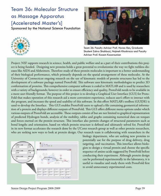
Project: NSF supports research in science, health, and public welfare and as a part of their contributions this proj-ect is being funded. Designing new proteins holds a great potential to revolutionize the way we fight ruthless dis-eases like AIDS and Alzheimers. Therefore study of these protein molecules is important to a better understanding of their biological performance, which primarily depends on the spatial arrangement of these molecules. At the University of Connecticut ongoing research on the use of kinematic models of protein structures has led to the development of a software package named ProtoFold. This software uses kinematic methodologies to predict 3D conformation of proteins. This comprehensive computer software is coded in MATLAB and is used by researchers with a variety of backgrounds; however in order to ensure efficiency and quality, ProtoFold needs to be available in a more user-friendly format. The purpose of this project is to develop a Graphical User Interface [GUI] for Proto-Fold that makes operation of this research aid a more convenient experience, reduces user’s effort to interact with the program, and increases the speed and usability of this software. In this effort MATLAB’s toolbox (GUIDE) is used to develop the Interface. This GUI enables ProtoFold users to upload a file containing geometrical informa-tion of a protein and displays different outputs of ProtoFold. This GUI offers different menu options under which various outputs of ProtoFold are accessible. These outputs consist of but are not limited to graphical representation of predicted Hydrogen bonds, analysis of the mobility, tables and graphs containing numerical data on torques and forces exerted on the protein structure. This interface also permits changes of structural parameters such as bond lengths and orientation, based on which protein structure is defined and ultimately solved for. ProtoFold in its new format accelerates the research done by the UConn research group as well as other protein researchers, who are seeking new ways to look at protein design. Our research team is collaborating with researchers in the
biology department, who are seeking new proteins to potentially use for the purpose of drug delivery, drug targeting, and vaccination. This interface allows biolo-gists to design a virtual protein and choose the specific sequence of amino acids suggested by ProtoFold before conducting their experiment. Although protein design can be performed experimentally in the laboratory, it is useful to visualize and study them with ProtoFold first to avoid unnecessary experimental costs.
Team 36: Faculty Advisor Prof. Horea Ilies, Graduate Student Zahra Shahbazi, Najmeh Khoshreza and Faculty Advisor Prof. Kazem Kazerounian
Team 36: Molecular Structure as Massage Apparatus [Accelerated Master’s]Sponsored by the National Science Foundation

Senior Design Project Program 2008-2009 Page �0
Project: This project involves an experimental and analytical in-vestigation of water transport in Polymer Electrolyte Fuel Cells. PEFCs are devices in which hydrogen and oxygen react to produce electricity and water. The operation of a PEFC requires the conduction of protons across a poly-mer membrane, which is more conductive to protons, therefore more effective, when it is sufficiently hydrated. The product water of fuel cells can be used to maintain the membrane hydration if it is not removed very rapidly. On the other hand, if water is not removed rapidly enough, it may condense inside the tiny pores of the fuel cell, and inhibits the ability of reactant gases to reach the reaction sites, consequently reducing the cell performance. These conflicting requirements lead to a strong need for accurate physical models of water transport to optimize the cell operation, typically called “water management.”
This study focuses on determining the water content profiles across the thickness of the diffusion media that sepa-rate the membrane electrode assemblies from the gas flow channels in these fuel cells. Cell hardware and other experimental equipment were designed and built for neutron radiography experiments to determine the water dis-tribution in a fuel cell during operation, and in these experiments a specially designed fuel cell is placed in the path of a neutron beam that is incident on a neutron detector. The liquid water in the fuel cell scatters the neutrons out of the beam so that they do not strike the detector. This results in an attenuation image that can be used to
determine how much water is in vari-ous locations in the cell. The Neutron Imaging Facility at the National In-stitute of Standards and Technology was used for the experiments. Data acquired from neutron radiography in conjunction with in-situ scanning electron microscopy data, for which a fixture was constructed, are used to characterize the interface between the two layers of the diffusion media. A mathematical model was developed to describe water transport across the composite diffusion media, and model predictions were shown to support the experimental findings.
Team 37: Faculty Advisor Prof. Ugur Pasaogullari and Joshua Preston
Team 37: Studies of Water Transport in PEM Fuel Cells [Accelerated Master’s]
Sponsored by the National Science Foundation

Senior Design Project Program 2008-2009 Page �1
Project: The ideal imaging system for imaging of combustion and plasma systems has a short depth-of-field and a large working distance, due to high temperatures. Planar Laser-Induced Fluorescence is an industry standard for such applications, but it is expensive and cannot be easily adapted to fit the imaging needs. Cassegrainian optical systems, as used in telescopes, have large working distance but typically have large depths of field. Researchers have shown recently that Cassegrain systems can be optimized to improve depth resolution. A Cassegrain optical system has been designed and constructed to meet requirements for imaging applications in UConn’s combus-tion and plasma experiments. The optimized system provides a low-cost imaging system with the desired narrow depth-of-field and has proven itself to be a useful tool in producing spatially-resolved images of natural flame emissions.
Team 34: Kathryn Gosselin and Faculty Advisor Prof. Michael Renfro
Team 38: Design and Construc-tion of a Narrow Depth-of-Field Optical Imaging System [Accelerated Master’s]
Sponsored by the National Science Foundation

Senior Design Project Program 2008-2009 Page �2
Project: The Army Research Office has expressed interest in researching fuel cells for the purposes of replacing battery packs carried by soldiers. Perfecting a fuel cell design to be used in the field can significantly reduce the load placed on a soldier. One of the largest losses in a fuel cell is due to ohmic overpotentials. A portion of the ohmic overpotential is attributed to the resistance of the electrolyte membrane to proton transport. This proton transport is essential to the basic operation of a fuel cell. It has been shown that water content is strongly related to membrane conductivity. The specific target of this project was to better understand diffusion within a fuel cell membrane. Diffusion is one of multiple mechanisms governing water transport within the membrane. A numeri-cal model has been developed to characterize this process and an experiment has been created to isolate this pro-cess. The experiment was used to validate the model and governing theory for diffusion in a fuel cell membrane.
Team 39: Faculty Advisor Prof. Wilson Chiu, Timothy Webb, and Timothy Myles
Team 39: Direct Methanol Fuel Cell for Portable Power Appli-cations [Accelerated Master’s]
Sponsored by the Army Research Office
Nafion 117
N2
N2 + H2O N2 + H2O
N2 + H2O
H2O H2O
Nafion 117Nafion 117
N2
N2 + H2O N2 + H2O
N2 + H2O
H2O H2O

Rich BonazzaChris BuckridgeSerge DoyonLaurie HocklaEmily JeromeChris LaRosaTom MealyIgor ParsadanovJacqueline Veronese
Thomas J. BarberJohn C. Bennett, Jr.Zbigniew M. BzymekBaki M. CetegenWilson K. S. ChiuAmir FaghriTai-Hsi FanHorea IliesRobert G. JeffersEric H. JordanKazem KazerounianKevin D. Murphy Nejat OlgacUgur PasaogullariMichael W. RenfroJiong Tang Marty WoodBi Zhang
Faculty Mentors
Assisting Staff
Thank you!
Senior Design
2009

Yes, together we will contribute to economic, social and environmental progress. Through thedevelopment of advanced public transport and cleaner electric power production, 65,000 Alstomemployees in over 70 countries are helping to address some of the key issues that face this planettoday. If you are looking for a world of economic, social and environmental change, look no further. As a leading global player in energy and transport infrastructures we suggest it's time to act and think of the future. Your future.www.careers.alstom.com
Publ
icis
Con
sult
ants
IRH
Phot
os A
lsto
m 2
007
Ready toteam up withtalented people?
Alstom-G4264-190x254pp 30/08/07 10:51 Page 1


Senior Design Project Program 2008-2009 Page ��
2007-2008 Demonstration Day AwardsCash prizes ($1500, $1000, $500) are awarded to the outstanding ME senior design teams, as judged by a panel of engineers from industry. Faculty also award a Professor’s Choice prize to the team that most successfully applied the fundamental principles of Mechanical Engineering to their solution. Performance is determined by the team’s understanding of the project, approach to solving the problem, management of the effort, and achievements.
First place: Unilever Bottle Sorting ChuteSponsored by Unilever Corporation Dale Humphries, Mike Doyle, and Kyle Johnson redesigned bottle sorting chutes to allow all four bottle sizes used by the company to be accomdated with one chute. The design uses a “V” shaped chute with an adjusting mechanism to accom-modate the four bottle sizes and eliminates a common problem of bottle jamming and sound reduction mechanisms to reduce machine noise levels.
Second place: External Lubrication in a Tablet PressSponsored by PfizerAlexander Dickau, Adam Gower, and John Tobin developed an external lubri-cation system design for a tablet press that eliminates deficiencies of current commercial lubrication methods. The team’s design consisted of a rotating disk which acts as a measuring and timing device, changing the angular velocity and the size of the cavities according to the tablet press. Suction from a venturi device moves the lubricant from the disk to the nozzle, where a wedge is used for proper distribution onto the tooling.
Third place: Helicopter Maintenance Crane Mobile Base Design Sponsored by ASMLKenneth Johnson, Andrew Johnston, and Kirk Scheel designed improvements to a mobile base for a U.S. Army maintenance crane. The base system is capable of supporting 1300 lbs, is easily moved by one person, and does not require any changes to the existing crane system. A counterweight design concept was used to replace the current base. The design reduced the size, while a handle/wheel system with power-start technology maximized the maneuverability. Assembly was made easier by a winch system previously used in the existing base.
Professor’s Choice Prize: Improving the Accuracy and Repeatability of the Block Shear MethodSponsored by Henkel LoctiteAndrew Amann and Caleb DeValve conducted a top to bottom analysis of the ASTM D4501, a standard for block shear testing of adhesive joint shear strength used by Henkel This method had been found to produce coefficient of variance between data points. The team determined that the development of a curing fixture to be used in conjunction with a testing fixture would better control the specimen geometry to significantly increase control over statistical variations introduced during the bonding and testing process. The improved methodology reduced the coefficient of variance and increased the reliability.

Senior Design Project Program 2008-2009 Page ��
Sponsors
AlstomASML DominionGeneral Dynamics / Electric BoatGeneral Electric Gentex Optics / EssilorHabco Inc.Hamilton Sundstrand
Henkel Loctite OSIM Otis ElevatorPitney BowesPfizerPratt&WhitneyRBC BearingsRogers Corp. Siemon
Unilever UTC PowerWestinghouse Electric Wilkinson SwordWindham Dental GroupWiremold LegrandArmy Research OfficeNational Science FoundationUConn Foundation
Mr. Brian Montanari, Habco Inc.‘Lean Management’
Mr. Thomas Meyer, (P&W retired)‘Fatigue in the Real World’
Professor Robert G. Jeffers‘Critical Path Method, PERT’
Mr. Raja Maharajah, Pratt & Whitney‘Patent Law and Intellectual Property’
Mr. Samuel Schrager, Esq., UConn School of Business‘Strict Liability and Product Liability’
Mr. Richard Dino, UConn School of Business‘Entrepreneurship’
Mark Austin, Paul Taormina, and Charles Warren, CT Society Prof. Engineers‘Professionalism & Ethics’
Guest Lecturers

THE EAGLE IS EVERYWHERE.
From military and commercial to business, regional and space applications,Pratt & Whitney provides a world of economic and environmental change.Power your future. Pratt & Whitney. The Eagle is everywhere.
www.pw.utc.com

(Electric Boat is an SEI rated and ISO9001 organization)

