helpful: flexible architecture to control heterogeneous
TRANSCRIPT

UNIVERSIDADE FEDERAL DO RIO GRANDE DO SULINSTITUTO DE INFORMÁTICA
PROGRAMA DE PÓS-GRADUAÇÃO EM COMPUTAÇÃO
GUSTAVO HERMÍNIO DE ARAÚJO
HELPFUL: Flexible Architecture toControl Heterogeneous Low Power Wide
Area Networks
Thesis presented in partial fulfillmentof the requirements for the degree ofMaster of Computer Science
Advisor: Prof. Dr. Juergen RocholCoadvisor: Prof. Dr. Cristiano Bonato Both
Porto AlegreJanuary 2020

CIP – CATALOGING-IN-PUBLICATION
Araújo, Gustavo Hermínio de
HELPFUL: Flexible Architecture to Control HeterogeneousLow Power Wide Area Networks / Gustavo Hermínio de Araújo.– Porto Alegre: PPGC da UFRGS, 2020.
88 f.: il.
Thesis (Master) – Universidade Federal do Rio Grande do Sul.Programa de Pós-Graduação em Computação, Porto Alegre, BR–RS, 2020. Advisor: Juergen Rochol; Coadvisor: Cristiano BonatoBoth.
1. Software-defined networking. 2. Low power wide area net-work. 3. Network programmability. I. Rochol, Juergen. II. Both,Cristiano Bonato. III. Título.
UNIVERSIDADE FEDERAL DO RIO GRANDE DO SULReitor: Prof. Rui Vicente OppermannVice-Reitora: Profa. Jane Fraga TutikianPró-Reitor de Pós-Graduação: Prof. Celso Giannetti Loureiro ChavesDiretora do Instituto de Informática: Profa. Carla Maria Dal Sasso FreitasCoordenador do PPGC: Prof. Luciana Salete BuriolBibliotecária-chefe do Instituto de Informática: Beatriz Regina Bastos Haro

ABSTRACT
Low Power Wide Area Networks (LPWAN) are candidates to coexist with traditional cellularnetworks by coping with different types of requirements such as density, reliability, and latency.However, there is no one-size-fits-all technology that can address all the needs of IoT appli-cations. For this reason, the integration of heterogeneous LPWAN becomes necessary. SDNprovides a powerful approach by creating a programmable, dynamic, and flexible architecture.Some studies investigate the SDN paradigm to provide a programmable network to IoT appli-cations. Nevertheless, these studies do not take into account the limited capacity of SDN-basednetworking devices to store the forwarding rules in its architectures. This thesis presents theHELPFUL, an SDN-based architecture that creates a common control abstraction among LP-WAN technologies (e.g., LoRa, NB-IoT) running on top of virtualized base stations. We alsodiscuss four rule management strategies for use with HELPFUL, providing support for singleand multiple tables. We evaluate our proposal with a series of experiments with a prototypedeveloped using the P4 language. Results show which HELPFUL is flexible enough to changethe management strategy to the best fit with the network demands. Consequently, it can reducethe number of messages on the control channel exchanged between the Controller and Gate-ways. Finally, HELPFUL adds minimal overhead to network performance, regardless of therule management strategy chosen.
Keywords: Software-defined networking. Low power wide area network. Network pro-grammability.

HELPFUL: Uma arquitetura para controle deLow Power Wide Area Network heterogenias
RESUMO
Low Power Wide Area Networks (LPWAN) são candidatas a coexistir com as redes celularestradicionais por lidar com diferentes tipos de requisitos como densidade, confiabilidade e latên-cia. Entretanto, não existe uma tecnologia LPWAN que consiga atender todas as necessidadesdas aplicações de Internet das Coisas (IoT). Por essa razão, a integração de diferentes tecno-logias LPWAN se faz necessária, criando assim, uma rede LPWAN heterogenia. SDN forneceuma abordagem poderosa, criando uma arquitetura programável, dinâmica e flexível. Algunsestudos já investigam a aplicação do paradigma SDN para fornecer uma rede programável paraaplicações IoT. No entanto, esses estudos não levam em consideração a capacidade limitada dosdispositivos de rede baseados em SDN para armazenar as regras de encaminhamento. Nestadissertação é proposto HELPFUL, uma arquitetura baseada nos conceitos definidos pelas Re-des Definidas por Software (SDN) que cria uma abstração comum entre diferentes tecnologiasLPWAN que rodam sobre estações base virtualizadas. Nós também discutimos quatro estraté-gias de gerenciamento de regras para serem utilizadas com HELPFUL, provendo suporte parauma única ou múltiplas tabelas. Nós avaliamos nossa proposta com uma serie de experimentoscom protótipo desenvolvimento utilizando a linguagem P4. Os resultados mostram que HELP-FUL é flexível o suficiente para que a estratégia de gerenciamento de regras na tabela de fluxosseja alterada para melhor se adequar as necessidades da rede. Consequentemente, HELPFULreduz a quantidade de mensagens no canal de controle trocadas pelos controlador e gateway.Finalmente, HELPFUL adiciona uma sobrecarga mínima ao desempenho da rede independenteda estratégia escolhida.Palavras-chave: Redes Definidas por Software; Low Power Wide Area; Programabilidade derede.

LIST OF FIGURES
2.1 Transmission Distances Between Wireless Technologies . . . . . . . . . . 162.2 LoRaWAN Architecture . . . . . . . . . . . . . . . . . . . . . . . . . . . 202.3 LoRaWAN Packet Header . . . . . . . . . . . . . . . . . . . . . . . . . . 212.4 SDN Architecture . . . . . . . . . . . . . . . . . . . . . . . . . . . . . . . 252.5 Flow table structure . . . . . . . . . . . . . . . . . . . . . . . . . . . . . . 272.6 PISA architecture . . . . . . . . . . . . . . . . . . . . . . . . . . . . . . . 28
3.1 Query result: number of indexed documents by year . . . . . . . . . . . . 31
4.1 HELPFUL architecture overview. Gray boxes represent the architecture’splanes, each one comprised of multiple components, depicted as whiteboxes. Arrows illustrate the data flows that may exist among the archi-tecture’s components. . . . . . . . . . . . . . . . . . . . . . . . . . . . . . 39
4.2 Example of the Translator Packets . . . . . . . . . . . . . . . . . . . . . . 424.3 Table Miss Sequence Diagram. . . . . . . . . . . . . . . . . . . . . . . . . 464.4 Control table update process. . . . . . . . . . . . . . . . . . . . . . . . . . 47
5.1 HELPFUL implementation tools. . . . . . . . . . . . . . . . . . . . . . . 505.2 Experimentation scenario. . . . . . . . . . . . . . . . . . . . . . . . . . . 525.3 Number of rules installed in the flow table. . . . . . . . . . . . . . . . . . 555.4 Number of controller interventions. . . . . . . . . . . . . . . . . . . . . . 565.5 Results for table hit ratio. . . . . . . . . . . . . . . . . . . . . . . . . . . . 575.6 Table lookup time. . . . . . . . . . . . . . . . . . . . . . . . . . . . . . . 585.7 Transmission latency. . . . . . . . . . . . . . . . . . . . . . . . . . . . . . 585.8 Lost packets. . . . . . . . . . . . . . . . . . . . . . . . . . . . . . . . . . 59

LIST OF TABLES
3.1 SDN Architectures with focus on IoT. . . . . . . . . . . . . . . . . . . . . 323.2 Flow Table Management Strategies. . . . . . . . . . . . . . . . . . . . . . 35
5.1 Application Profile Specifications. . . . . . . . . . . . . . . . . . . . . . . 515.2 Application Profile Specifications. . . . . . . . . . . . . . . . . . . . . . . 535.3 Experimentation parameters. . . . . . . . . . . . . . . . . . . . . . . . . . 54
LIST OF ABBREVIATIONS AND ACRONYMS
16-QAM 16-Quadrature Amplitude Modulation
3GPP 3rd Generation Partnership Project
5G Fifth-Generation
6LoWPAN IPv6 Over Low Power Wireless Personal Area Networks
8PSK 8-Phase-shift keying
ADR Adaptive Data Rate
AES Advanced Encryption Standard
API Application Programming Interface
ASIC Application Specific Integrated Circuits
bps Bits per Second
BS Base Station
CAPEX Capital Expenditure
DPSK Differential Phase-Shift Keying
dst Destination
EC-GSM-IoT Extended Coverage Global System Mobile for IoT
eDRX Extended Discontinuous Reception
FDMA Frequency Division Multiple Access
FEC Forward Error Correction
GMSK Gaussian Minimum Shift Keying
GSM Global System for Mobile
HARQ Hybrid Automatic Repeat Request
Hz Hertz

IoT Internet of Things
IPv4 Internet Protocol version 4
ISM Industrial, Scientific and Medical
LPWAN Low Power Wide Area Network
LRU Least Recently Used
LTE Long Term Evolution
LTE-M Long Term Evolution Machine Type Communication
m Meters
MAC Media Access Control
MBF Multiple Bloom Filter
MPLS Multi-Protocol Label Switching
NB-IoT Narrowband Internet of Things
OFDMA Orthogonal Frequency Division Multiple Access
ONF Open Network Foundation
OPEX Operational Expenditure
P4 Programming Protocol independent Packet Processors
PRB Physical Resource Block
PSM Power Saving Mode
QoS Quality of Service
QPSK Quadrature Phase Shift Keying
RAM Random Access Memory
REST Representational State Transfer
RPL Low-Power and Lossy Networks
SDN Software-Defined Networking
SRANS Static Random-Access Memory
src Source
TCAM Ternary Content Addressable Memory
TCP Transmission Control Protocol
TDMA Time Division Multiple Access

UDP User Datagram Protocol
UNB Ultra-Narrowband
VLAN Virtual Local Area Network
WLAN Wireless Local Area Network
WPAN Wireless Personal Area Network
WSN Wireless Sensor Network

CONTENTS
1 INTRODUCTION . . . . . . . . . . . . . . . . . . . . . . . . . . . . . . . . . 12
2 BACKGROUND . . . . . . . . . . . . . . . . . . . . . . . . . . . . . . . . . . 14
2.1 Contextualization . . . . . . . . . . . . . . . . . . . . . . . . . . . . . . . . . . 14
2.2 Low Power Wide Area Network . . . . . . . . . . . . . . . . . . . . . . . . . . 16
2.3 Review of the LPWAN technologies . . . . . . . . . . . . . . . . . . . . . . . . 18
2.3.1 Unlicensed bands LPWAN technologies . . . . . . . . . . . . . . . . . . . . . 19
2.3.2 License bands LPWAN technologies . . . . . . . . . . . . . . . . . . . . . . . 23
2.4 Software-Defined Network . . . . . . . . . . . . . . . . . . . . . . . . . . . . . 24
2.4.1 Architecture Overview . . . . . . . . . . . . . . . . . . . . . . . . . . . . . . 24
2.4.2 Enabling Platforms . . . . . . . . . . . . . . . . . . . . . . . . . . . . . . . . 26
2.5 Chapter Summary . . . . . . . . . . . . . . . . . . . . . . . . . . . . . . . . . 29
3 RELATED WORK . . . . . . . . . . . . . . . . . . . . . . . . . . . . . . . . . 30
3.1 Systematic Literature Review . . . . . . . . . . . . . . . . . . . . . . . . . . . 30
3.2 SDN Architectures for IoT . . . . . . . . . . . . . . . . . . . . . . . . . . . . . 32
3.3 SDN Table Management . . . . . . . . . . . . . . . . . . . . . . . . . . . . . . 34
3.4 Discussion about Related Work . . . . . . . . . . . . . . . . . . . . . . . . . . 36
3.5 Chapter Summary . . . . . . . . . . . . . . . . . . . . . . . . . . . . . . . . . 37
4 HELPFUL: CONCEPTUAL SOLUTION . . . . . . . . . . . . . . . . . . . . . 38
4.1 Architecture Overview . . . . . . . . . . . . . . . . . . . . . . . . . . . . . . . 38
4.2 HELPFUL Forwarding . . . . . . . . . . . . . . . . . . . . . . . . . . . . . . 40
4.3 HELPFUL Controller . . . . . . . . . . . . . . . . . . . . . . . . . . . . . . . 43
4.4 HELPFUL Application . . . . . . . . . . . . . . . . . . . . . . . . . . . . . . . 44
4.5 HELPFUL Management . . . . . . . . . . . . . . . . . . . . . . . . . . . . . . 44
4.6 HELPFUL Interaction . . . . . . . . . . . . . . . . . . . . . . . . . . . . . . . 45
4.7 Chapter Summary . . . . . . . . . . . . . . . . . . . . . . . . . . . . . . . . . 48

5 HELPFUL EVALUATION . . . . . . . . . . . . . . . . . . . . . . . . . . . . . 495.1 Framework Implementation . . . . . . . . . . . . . . . . . . . . . . . . . . . . 495.2 Methodology . . . . . . . . . . . . . . . . . . . . . . . . . . . . . . . . . . . . 515.3 Impact of management strategies in flow tables . . . . . . . . . . . . . . . . . 545.4 Impact on the network infrastructure . . . . . . . . . . . . . . . . . . . . . . 565.5 Chapter Summary . . . . . . . . . . . . . . . . . . . . . . . . . . . . . . . . . 60
6 CONCLUSION AND FUTURE WORK . . . . . . . . . . . . . . . . . . . . . 616.1 Summary of Contributions . . . . . . . . . . . . . . . . . . . . . . . . . . . . 616.2 Final Remarks and Future Work . . . . . . . . . . . . . . . . . . . . . . . . . 62
REFERENCES . . . . . . . . . . . . . . . . . . . . . . . . . . . . . . . . . . . . . 63
APPENDIXA RESUMO . . . . . . . . . . . . . . . . . . . . . . . . . . . . . . 66
APPENDIXB PUBLISHED PAPER – SBRC 2017 . . . . . . . . . . . . . . . 68
APPENDIXC PUBLISHED PAPER – LANCOMM STUDENT WORKSHOP2019 . . . . . . . . . . . . . . . . . . . . . . . . . . . . . . . . . . . . . . . . 84
APPENDIXD JORNAL SUBMITED – JNCA 2019 . . . . . . . . . . . . . . . 88

12
1 INTRODUCTION
The next generation of wireless networks is being designed to provide connectivity to mul-tiple Internet of Things (IoT) applications, such as smart homes, industry 4.0, and wearabledevices (MINOLI; SOHRABY; OCCHIOGROSSO, 2017). Such new IoT applications willpush the boundaries of current communication architectures, demanding coexistent IoT net-works, e.g., using Low Power Wide Area Networks (LPWAN) technologies (ALI et al., 2017).The coexistence of heterogeneous LPWAN infrastructures enables the usage of the best fea-tures that each technology provides, addressing multiple requirements, for example, massivemachine-type communication and low-latency communication (BRUNS et al., 2015).
The deployment and operation of several heterogeneous networks, each one supporting alimited number of IoT devices, evidences research challenges that still require proper investi-gation(RAZA; KULKARNI; SOORIYABANDARA, 2017). Firstly, current LPWAN technolo-gies are not designed to coexist with each other, as each LPWAN implements individual controlprotocols, leading to uncoordinated wireless access (POORTER et al., 2017). Secondly, theassumption of multiple wireless access technologies in the traditional architecture of cellularnetworks would lead to prohibitive deployment costs of transmitter cells (GALLO et al., 2016).
Aiming to cope with these challenges, Base Stations (BS) virtualization was proposed as asolution to reduce CAPital EXpenditure and Operational Expenditure (CAPEX/OPEX) of cel-lular networks through infrastructure sharing (KIST et al., 2018). However, virtualization addsthe need for new access control to the infrastructure to manage the uncontrolled access to thespectrum used by the LPWAN. Software-Defined Networking (SDN) provides a powerful ap-proach by creating a programmable, dynamic, and flexible architecture that allows the abstrac-tion from traditional hardware-based protocol implementations into a software-based networkcontroller (KREUTZ et al., 2015). In this sense, some studies have applied the SDN paradigmto provide a programmable network to IoT applications (LUO; TAN; QUEK, 2012; GALLOet al., 2016; BADDELEY et al., 2018; BERA et al., 2018). Nevertheless, these studies do nottake into account the limited capacity of SDN-based networking devices to store the forwardingrules in its architectures. For example, the tables have a limited rule storage capacity, whichis several orders of magnitude smaller than that required for the operation of certain types ofnetwork, including LPWAN (NGUYEN et al., 2016). This problem becomes worse when ap-

13
plied in LPWAN environments where a massive amount of end-nodes in a network (e.g., ≈ 106
devices per km2 (RAZA; KULKARNI; SOORIYABANDARA, 2017)), making it necessary tomanage the rules of the flow tables.
In this thesis, we propose HELPFUL: a flexible architecture to control heterogeneous low
power wide area networks to enable various LPWAN technologies to coexist whit scalabilityguarantees. HELPFUL is an SDN-based architecture that creates a common control abstractionamong LPWAN technologies running on top of virtualized BSs. The main contributions ofour work are two-fold: (i) the proposal of an architecture which adds an abstraction layer thattranslates the heterogeneous control protocols to a homogeneous set of messages, and (ii) astrategy based on multiple table rule management to address the scalability issues present inthe SDN-based devices. Our proposal enables the unification of technology-specific controlinto a single cross-technology controller, allowing infrastructure and spectrum access to beharmonized.
We developed a prototype based on the P4 language that allows programmability of bothcontrol and forwarding planes to validate HELPFUL. In our first evaluation, we enumerate aseries of strategies to manage flow table rules when using the HELPFUL architecture. Wedefine the metrics to analyze HELPFUL with each strategy, such as the number of rules installedin the flow table, the number of controller interventions, and the number of table hits. Theseresults indicate the best strategies regarding the reduction of the number of rules installed in flowtables. Our second evaluation considers the overhead of HELPFUL on the network architecture,including table lookup time, latency, and lost frames. The results show that HELPFUL producesa minimum impact on the network. For example, HELPFUL presented ≈ 0.92ms of lookuptime in a scenario analyzed. Moreover, the HELPFUL architecture added minimal networklatency of ≈ 2ms and the number of lost frames averaging 1.5%.
The remaining of this thesis is organized as follows. In Chapter 2, we present the back-ground with the main concepts related to the new IoT applications, the Low Power Wide AreaNetwork and Software-Defined Networking. In Chapter 3, we present a review of the mostrelevant research and related works for this thesis. In Chapter 4, we introduce HELPFUL andshow a description and overview of its architectural components. In Chapter 5, we present out-line the implementation of HELPFUL showing how each component communicates with othersand internal details of its architecture. After, we present our evaluation and associated results,including a performance analysis of the framework. Finally, in Chapter 6, we conclude thisdissertation presenting final remarks and future work.

14
2 BACKGROUND
In this Chapter, we present the basic concepts for understanding this work. First, on Section2.1 we position our work on the Internet of Things (IoT) landscape. Next, in Section 2.2 wedescribe the Low Power Wide Area Network technology focus on the main design goals andtechniques. Finally, on Section 2.4 we present the Software-Defined Networking (SDN) anddescribe how this paradigm can be used in the wireless environment.
2.1 Contextualization
The fifth-generation (5G) of cellular networks is being designed to provide connectivityto the Internet of Things (IoT) applications such as smart city, healthcare, smart grid, smartmetering, industrial assets monitoring, agriculture, and, wildlife monitoring and tracking. Theseapplications require a new set of communication requirements:
• Long-Range Communication: It is desirable for agriculture or wildlife tracking appli-cations where sensors can be deployed over a large geographical area with just a singlebase station reducing the capital expense (CAPEX).
• Low Energy Consumption: It is desirable to reduce the maintenance cost of the end-devices by extended their battery live. This feature is desirable for applications that needto deploy end-devices in remote areas where it is difficult to provide any maintenance.
• Support for a Massive Number of Devices per Cell: It is desirable for applications thatneed a large deploy of end-devices over a geographical area like smart cities and industrialapplications. As the number of final nodes increases, the accuracy of these applicationsalso tends to increase.
• Low Deployment Cost: It is desirable to reduce the CAPEX of the sensors of his appli-cations and allow the deployment of more sensors.
However, these requirements are not met by the current wireless personal area network(WPAN), wireless local area networks (WLAN) and, cellular networks communication tech-nologies (RAZA; KULKARNI; SOORIYABANDARA, 2017).

15
The WPAN and WLAN are not recommended for the new IoT applications because therange of these technologies is limited to a few hundred meters. For example, the maximumdistance that Zigbee can provide communication is only 100 meters, and Wi-Fi only transmitsover 30 meters. The range of WPAN and WLAN technology can be extended by the usageof multi-hop mesh networking. Where end-devices need to listen to the environment to relaythe traffic of the other end-devices and forward to the gateway. Also, the end-devices cannot bearbitrarily deployed having specific positions to provide the mesh network, and cannot be movedanywhere (XIONG et al., 2015). This approach is not desirable due these large deploymentsare prohibitively expensive, and the end-devices waste energy forwarding traffic of the otherend-devices.
The cellular network technologies can provide wide area coverage. However, these tech-nologies bring two disadvantages that make it unfeasible for the new IoT applications. First, thecellular technologies were design to deal with complex waveforms, optimized for voice, high-speed data services, and text. Due to these design decisions, the cellular networks do not achieveenergy-efficient high enough for the new IoT applications. Secondly, for these technologies toachieve low power consumption, there is a clear need to strip complexity and reduce cost. It isimportant to notice that some current cellular networks are being adapted to provide communi-cation to low power devices. Efforts in this direction are underway for cellular networks by theThird Generation Partnership Project (ALI et al., 2017).
The Low Power Wide Area Networks (LPWAN) represent a novel paradigm in providingcommunication to the IoT applications. LPWAN takes different tradeoffs than the current shortwireless and cellular technologies. These technologies offer long-range communication (tensof kilometers), low energy consumption (tens of years of battery live time), high scalability(tens of thousands of devices per cell), and low deployment cost. However, to achieve theserequirements, the LPWAN operates at the expense of low data rates (tens of kilobytes per sec-ond) and higher latency (order of seconds). These technologies are not indicated to operate withapplications that need high throughput and ultra-low latency, such as wireless industrial control.
Nevertheless, LPWAN are indicated to applications that exchange a small amount of data,infrequently, over long distances and, with end-devices distributed over a large geographicalarea such as smart cities, smart metering, home automation (RAZA; KULKARNI; SOORIYA-BANDARA, 2017). Figure 2.1 shows an example of the range of different wireless technologiesthat are present in this section. In the next section, we will describe the techniques used by theLPWAN in order to achieve these requirements. Also, we present an overview of the leadingLPWAN technologies.

16
Figure 2.1: Transmission Distances Between Wireless Technologies
0m 100m 1Km 10Km 15Km
WPAN
(Zigbe
e) WLAN
(802.1
1ah)
Cellular
(LTE) LP
WAN
(LoRa)
Source: the author (2018)
2.2 Low Power Wide Area Network
Research efforts for future 5G networks have to provide communication to IoT applicationsmeeting the requirements of low power consumption, long-range coverage, and support for amassive number of end-devices. LPWAN will play an essential role by complementing tra-ditional cellular networks to address the communications requirements and provide spectrumefficiency for IoT applications (ALI et al., 2017). In this Section, we present the primary designgoals of the LPWAN technologies and the techniques used to achieve these goals. We organizeeach one of the goals in bullet points that describe the techniques used. The goals are:
1. Long Distance Communication: The main innovation that the LPWAN technologiesproposed is the long-distance communications with an excellent signal propagation toreach indoor places (e.g., basements, industrial complex). With this wide area coverage,the end-devices can transmit data over tens of kilometers of their base stations in an urbanor rural environment. To achieve this goal, the LPWAN used sub-1GHz bands and somemodulation techniques (e.g., narrowband, ultra-narrowband, and spread spectrum). Sub-1GHz offers robust and reliable communication at low power budgets and is less sensitiveto physical obstacles (e.g., walls, buildings) (ALI et al., 2017). It results in higher relia-bility and enables long-range and low power communication. The side effect to use thesebands is the limited amount of available spectrum combined with the large propagationranges of the LPWAN will cause an inter-technology interference. The LPWAN tech-nologies use three kinds of modulation techniques to enable a range of tens of kilometers:narrowband, ultra-narrowband, and spread spectrum. Narrowband modulation providesa high link budget by encoding the signal in low bandwidth. Also, this technique sharesthe overall spectrum efficiently if multiple links. The noise level experienced inside asingle narrowband is also minimal. Therefore, no processing gain is required to decodethe signal at the receiver, resulting in a simple and inexpensive transceiver design. SomeLPWAN technologies carrier a signal in an ultra-narrowband (UNB). This technique re-duces the experienced noise and increasing the number of supported end-devices per unit

17
bandwidth, even more than a narrowband modulation. However, the effective data ratefor individual end devices decreases as well, thus increasing the amount of time the radioneeds to be kept ON. A spread spectrum technique is used for some LPWAN technolo-gies. This technique consists of spreading a narrowband signal over a wider frequencyband but with the same power density. Transmission using the spread spectrum is moreresilient to interference and robust to jamming attacks. However, more processing gainis required on the receiver to decode the message. Another outcome that this techniquebrings is that spreading a narrowband signal over a wide band results in less efficient useof the spectrum (RAZA; KULKARNI; SOORIYABANDARA, 2017).
2. Low Energy Consumption: One of the central promises of the LPWAN technologiesis the low energy consumption of the end-devices to transmit their traffic over long dis-tances. This is an essential requirement for various business opportunities. To reducethe energy consumption and achieve maximum energy efficiency, the LPWAN applies asequence of techniques: (i) topology specifications, (ii) duty cycle and, (iii) lightweightmedium access control. The LPWAN technologies specify a topology that connects theend-devices directly to the base stations. It results in a start topology that brings a consid-erable energy-saving advantage. Also, the end-devices do not need to waste energy listento other devices that want to relay their traffic (e.g., multi-hope mesh networks). Thus,the end-devices never exchange messages directly with each other. The base stations willintermediate all the possible communications. For example, if some end-device needsto transmit data to other end-device, first, it is necessary to transmit to the base station.Then the base station will transmit the data to do the end-device (RAZA; KULKARNI;SOORIYABANDARA, 2017). Radio duty cycling allows end devices to turn off theirtransceiver and just turned then on when it is required. The duty cycling mechanism de-pends on the application and traffic pattern. If an application needs to transmit some data,then the transceivers will wake up and transmit. If a downlink transmission is required,then the end-device needs to schedule with the base station. In the most LPWAN tech-nologies, the end-devices may listen for a short duration after their uplink transmissions toreceive a replay back. Another option is to listen at a scheduled time agreed with the basestation. This technique can be used in hardware components in order to reduce energyconsumption. The LPWAN adopts simple random access schemes (e.g., ALOHA). Theend-devices are the most-constrained elements transferring the complex task to the basestation to simplify the design of the end-devices. The LPWAN base station is capableof transmitting and listening from multiple end-devices using different channels and or-thogonal signals simultaneously. Also, the base station is responsible for mechanisms toadapt data rate, support mobility, and suppress network duplicates (RAZA; KULKARNI;SOORIYABANDARA, 2017).
3. Support of massive number of devices: Scalability is an essential requirement for LP-

18
WAN technologies. The LPWAN network will send low volumes of data of a large num-ber of end-devices. To cope up with the increased density of the end devices in certainareas, LPWA networks, like traditional cellular networks, will resort to dense deploy-ments of base stations. Not only the LPWA systems should scale to several connecteddevices, but each link should be optimized for reliable and energy-efficient communica-tion. Adapting the modulation schemes to reach distances while guaranteeing reliablecommunication at the same time requires efficient monitoring of link qualities and coor-dination between end devices and network. To accommodate as many connected devicesas possible, efficient exploitation of diversity in channel, time, space, and hardware isvital. Due to the low-power and inexpensive nature of the end devices, much of thisis achieved by cooperation from more powerful components in LPWA networks such asbase stations and backend systems. LPWA technologies employ multi-channel and multi-antenna communication to parallelize transmissions to and from the connected devices.Further, communication is made resilient to interference by using multiple channels anddoing redundant transmissions (XIONG et al., 2015).
4. Low deployment cost: The LPWAN technologies adopt some techniques to reduce thecapital expenses (CAPEX) and operating expenses (OPEX) for the end-users and networkoperations. The connective module of the end-devices will eventually cost less than a fewdollars. Thus, these reductions on the CAPEX and OPEX will result in the deploymentof the end-devices in a large geographical area. To achieve this goal, the LPWAN appliesa sequence of techniques. First, the LPWAN transceivers need to deal with simple wave-forms compared with the short-range wireless technologies and cellular networks. Also,the LPWAN does not have complex MAC schemes that reduce transceiver footprint, peakdata rates, and memory sizes, minimizing the hardware complexity and thus the cost.Thunder, the LPWAN technologies apply a minimal infrastructure. A single LPWANbase station can connect tens of thousands of end-devices distribute over a large geo-graphical area and do not need to implement a pico or microcell (RAZA; KULKARNI;SOORIYABANDARA, 2017).
2.3 Review of the LPWAN technologies
In this Section, we highlight the leading LPWAN technologies. To better understanding thetechnologies present in this section, we divide into two groups: the LPWAN that uses the unli-censed band and the LPWAN that use license bands. The usage of license bands conflicts withthe low deployment cost goal. Due to this conflict, most of the LPWAN technologies use indus-trial, scientific, and medical (ISM) bands or TV-white spaces. However, the usage of the ISMbands will leave the LPWAN technologies to develop mechanisms of coexistence. Because theyare not designed to coexist with the existent wireless technologies. Second, since the amount

19
of available spectrum is much smaller and the propagation ranges much more extensive, thesetechnologies will cause interference at a much larger scale, leading to severe inter-technologyand inter-operator interference. Some LPWAN technologies that are deployed in the licensedband may share the existing cellular bands to avoid the additional licensing cost. However, toget better performance, a stand-alone licensed band can be acquired as well, a trend propri-etary LPWAN technologies may eventually follow to avoid performance degradation due to anincrease in several connected devices (RAZA; KULKARNI; SOORIYABANDARA, 2017).
This Section is organized as follows. In Subsection 2.3.1, we present the leading LPWANtechnologies that use unlicensed bands. To better understanding this work, we focus on Lo-Ra/LoRaWAN technology. In Subsection 2.3.2, we review the leading LPWAN technologiesthat use license bands. We will focus on Narrowband-IoT (NB-IoT) technology for the bestfuture understanding of this work.
2.3.1 Unlicensed bands LPWAN technologies
In this Subsection, we review the unlicensed bands LPWAN technologies. First, we presentLoRa/LoRaWAN technology. We decide to focus on LoRa/LoRaWAN because, further on thiswork, we reuse some concepts that are applied to technology. Also, we review Sigfox andWeightless, presenting the technical specifications of these technologies.
LoRa/LoRaWAN
LoRa/LoRaWAN is a technology developed by a consortium called LoRa Alliance with theproposal to provide connectivity over long distances and low energy consumption. LoRa isa physical layer technology that uses the Sub-1GHz band using a spread spectrum techniquedeveloped and commercialized by Semtech Corporation. The end-devices communicate withthe base stations using a chirp spread spectrum technique that spreads a narrow band input signalover a wider channel bandwidth. LoRa supports multiple spreading factors (7 to 12) to decidethe best tradeoff between rage and data rate. Higher spreading factors increase the distance thatan end-device can transmit to the base station at the expense of lower data rates. The data rateranges from 300 bps to 37.5 kbps depending on the spreading factor, and the distances may varybetween 15 Km to 20 Km. LoRa combines Forward Error Correction (FEC) with the spreadspectrum technique to increase the reliability of the transmission. The communication betweenend-devices and base stations is a half-duplex mode. To receive data from the base stationsthe end-devices open a received window 1 second after the transmission, and a second receivedwindow will be open 1 second after the first one. This mechanism improves energy efficiencyonce the end-device can turn off their transceivers while the window is not open. Also, thisstrategy allows a channel to receive a network control between the end-device and the basestation.

20
While LoRa defines the physical layer of the technology, LoRaWAN defines the networkarchitecture and up layer protocols. In Figure 2.2, it is possible to observe the network archi-tecture of the LoRaWAN network. The end-devices are the sensors where that has the functionto sense the environment and send their data to feed the IoT applications. In order to increasethe reliability of the communication, the end-devices transmit the data to all LoRa Gatewaysin the communication range. This approach generates duplicate messages that have to be treadlater by network control. The LoRa Gateway receives the messages from the end-devices andwill forward it to the Network Control through an IP standard communication technology (e.g.,Ethernet, Wi-Fi, GSM). The Network Server has the function to manage the network (e.g., elim-inate duplicate packets, schedules transmissions, send acknowledgments, and adapts data rates).Also, the Network Server forwards the data to the destination Application Server. Finally, theApplication Server will consume the data send by the end-devices.
Figure 2.2: LoRaWAN Architecture
End-DevicesLoRa
GatewayNetworkServer
Applica�onServer
Ethernet BackhaulLoRa
Source: the author (2018)
LoRa/LoRaWAN does not have a control channel. The control information and the userdata are transmitted using the same channel. To allow this, LoRaWAN defines a packet headerthat allows the network server to transmit MAC commands for the end-devices. In Figure2.3 it is possible to observe the LoRaWAN packet header. The first field of the header is theMAC header. It is used to specify the message type (MType) and the major version (Major)of the LoRWAN protocol. The MType defines indicating, among other things, whether it isan uplink or a downlink message and whether or not it is a confirmed message. The Majordefines the LoRaWAN version. The second field is the Device Address, a 2-bit identifier of theend-device. Seven bits are used as the network identifier, and 25 bits are used as the network

21
address of the end-device. The Frame Control (FCtrl) is to manage the network parameters(e.g., request confirmation, send/response MAC commands). The Frame Counter (FCount) isa frame counter used to the Network Server to identify if a frame if uplink or downlink. TheFrame Options (FOpts) is used to piggyback MAC commands on a data message. The FramePort (FPort) indicates if the frame has just MAC commands or some data do delivery to thedestination.
Figure 2.3: LoRaWAN Packet Header
(a) LoRa Frame Header
MHDR DevAddr FCtrl FCnt FOpts DataFPort
(b) MAC HeaderMType RFU Major
(c) Downlink FCrtlADR AckReq Ack FPending FOptsLen
(d) Uplink FCrtlADR AckReq Ack RFU FOptsLen
Source: the author (2018)
The FCtrl is used to control the network parameters of the end-devices. The Adaptive DataRate (ADR) field is used to inform to the end-device that the network server will set the data rateof the end-devices thought appropriated MAC commands. If these fields are not set, then theend-device will use the default data rate. If the data rate set by the network server is higher thanthe default data rate of the end-devices, the Adaptive Data Rate Acknowledgement Request(ADRAckReq) is used to confirm if the data transmitted is received. The Acknowledgement(Ack) field is used to confirm the previous data received. The Frame Pending (FPending) isused only in uplink transmissions is only used in downlink communication, indicating thatthe gateway has more data pending to be sent and therefore asking the end-device to openanother receive window as soon as possible by sending another uplink message. The frame-options length field (FOptsLen) in FCtrl byte denotes the actual length of the frame optionsfield (FOpts) included in the frame.
LoRaWAN defines MAC commands that allow customizing end-device parameters. Thesecommands can control the data rate and output power used by the device, as well as the num-ber of times each unconfirmed packet should be sent (LinkADRReq), the global duty cycle ofthe device (DutyCycleReq), changing parameters of the receive windows (RXTimingSetupReq,RXParamSetupReq) and changing the channels used by the device (NewChannelReq).

22
Others Unlicesend LPWAN
Sigfox technology is developed by the SigFox Network Operators (SNOs). This partnershipoffers an end-to-end LPWAN connectivity by deploying proprietary base stations and equippedwith cognitive software-defined radios and connect them to the backend servers using an IP-based network. The end-devices communicate with the base stations using a Binary Phase ShiftKeying (BPSK) modulation using an ultra-narrowband (100Hz, resulting in 8000 channels) ina Sub-GHz ISM band (868 MHz in Europe, 915 MHz in the USA). It allows for long-rangecommunication (30–50 km in rural areas and 3–10 km in urban areas) at low bitrate (100 bps).Sigfox was initially supported only uplink transmissions but later evolved to a bidirectionaltransmission. The downlink transmissions can only be made after an uplink communication.After an uplink transmission, the end device has to wait and listen for a response from the basestations. Also, Sigfox does not implement any collision avoidance mechanism. In summary,the SigFox technology is suitable for very specific, very low data rate uplink IoT applications.Because of its closed nature, it is difficult to innovate within SigFox for external researchers andcompanies. However, due to its popularity, it must be taken into account as a potentially harm-ful interfere for the other LPWAN technologies (RAZA; KULKARNI; SOORIYABANDARA,2017).
Weightless Special Interest Group (WeightLess-SIG) proposed an open LPWAN standard.Weightless technology has three different standards: Weightless N, Weightless W and, Weight-less P. Which one of these protocols provide a different set of feature (all of them offeringlong-range and low energy consumption). Weightless W achieves an excellent signal propa-gation by using the TV white-spaces. This protocol can support several modulation schemes16-Quadrature Amplitude Modulation (16-QAM) and Differential-BPSK (DBPESK) using anarrow band technique (resulting in 24 channels). Uplink transmission is made by using TimeDivision Multiple Access (TDMA), and downlink transmissions are made using the FrequencyDivision Multiple Access (FDMA). Also, Weightless has an encryption layer using AES 128.Weightless W can transmit packets of 10 bytes at a rate of 1 kbps to 10Mbps. The end-devicescan transmit to a base station over a 5 Km. The used of TV white spaces is allowed only ina few regions. For this motivation, Weightless-SIG defines the other two standards that useISM bands. Weightless P differs from the W version by using an ultra-narrowband modula-tion and is a one-way communication from the end-device to a base station. Because of that,this version uses less energy than the other Weightless versions. Also, this version use Sub-GHz ISM bands (868 MHz in Europe and 915 MHz in the USA) using a DBPSK scheme.Finally, the Weightless-P can be summarized as a Weightless-N version with two-way commu-nication. It modulates the signals using GMSK and QPSK. Full support for acknowledgmentsand bidirectional communication capabilities enable over-the-air upgrades of firmware (RAZA;KULKARNI; SOORIYABANDARA, 2017).

23
2.3.2 License bands LPWAN technologies
To address the new features of the IoT applications, the Third Generation Partnership Project(3GPP) is evolving the current cellular networks. In this Section, we highlight the main LP-WAN technologies that use licensed bands. In subsection 2.3.2 we highlight Narrowband-IoT(NB-IoT). In Section 2.3.2, we review LTE-M and EC-GSM-IoT, presenting the technical spec-ifications of these technologies.
NB-IoT
The Narrowband-IoT is a technology design to enhance the existent LTE network to pro-vide better support for IoT applications. NB-IoT reuses the design of the LTE network but withoptimization to provide a low power consumption. The full carrier bandwidth is 180 kHz, thesubcarrier spacing can be 3.75 kHz (only for the uplink) or 15 kHz, the highest modulationscheme is QPSK, there is only support for Frequency Division Duplex (FDD) and half-duplexoperation. The downlink of NB-IoT is based on OFDMA, and the transmission scheme usesonly one physical resource block (PRB) for the LTE network. The uplink is based on single-carrier FDMA. For uplink transmission, there are two possible operation modes, single-tonetransmission, and multi-tone transmission. In a single tone, either 3.75 kHz or 15 kHz subcar-rier spacing is allowed. In multi-tone, only 15 kHz subcarrier spacing can be used. Multi-tonetransmission enables grouping sets of 3, 6, or 12 subcarriers. Additionally, the minimum du-ration for the resource units used in scheduling depends on the number of assigned subcarriersand the operation mode, ranging from 1 ms in 12 sub-carriers multi-tone transmission to 32msin 3.75 kHz single tone transmission (ZAYAS; MERINO, 2017).
Regarding the MAC layer, NB-IoT introduces several changes to reduce power consump-tion and make scheduling more flexible and straightforward. Because of the lower throughputrequirements, a single hybrid automatic repeat request (HARQ) process is used. It allows re-moving the HARQ identifier from the scheduling assignments and thus uses a lower numberof control bits for higher efficiency and robustness. Additionally, uplink retransmissions areno longer synchronous but always adaptive and asynchronous both in uplink and downlink.It provides the network with tighter control on the UL scheduling while preventing undesiredperiodic retransmissions as they will be now generated only when explicitly requested. Also,NB-IoT uses a Power Saving Mode (PSM) that allows the end-device to inform the networkthat they will sleep indefinitely (WANG et al., 2017).
Others Licesend LPWAN
LTE enhancements for machine type communications is a fork of the traditional LTE net-work optimize for communication in long distances and high energy efficiency. This technol-

24
ogy was initially standardized in the 3GPP Release 13 specification, specifically refer to LTECatM1, suitable for IoT applications. To adapt the LTE technology to operate with low energyconsumption, a set of features have been cut. LTE-M only supports half-duplex communicationsto reduces the complexity of modem and antenna design. Also, a drop in the receive bandwidthfrom 20 MHz to 1.4 MHz in combination with a reduced transmission power will result in amore cost-efficient and low-power design. Like NB-IoT, the features of PSM and eDRX areadded to this standard in order to better energy efficiency. LTE-M can use Quadrature PhaseShift Keying (QPSK) or 16-QAM in both uplink and downlink transmissions. Transmission canbe made at a peak rate of 1Mbps. The end-devices can transmit to the base station at a distanceof 2.5Km in urban areas and 5km in rural or remote areas (ALI et al., 2017).
Extended Coverage Global System Mobile for IoT (EC-GSM-IoT) is the proposal of the3GPP of extending the traditional GSM to better server IoT applications. This standard reusesthe GSM infrastructure and applies a set of features in order to improve energy consumption.Like NB-IoT and LTE-M, this standard use eDRX and PSM to improve energy consumption.EC-GSM-IoT uses 900 MHz in a coverage area of the 15 km in downlink and uplink transmis-sion. Two modulation techniques, namely Gaussian Minimum Shift Keying (GMSK) and EightPhase Shift Keying (8PSK), provide variable data rates with the peak rate of 240 kbps with thelatter technique. The end-devices can transmit to the base station at a range of 15km (ALI etal., 2017).
2.4 Software-Defined Network
In this Section, we review the Software-Defined Networking paradigm and present the mainconcepts need to understand this work. In subsection 2.4.1, we present the basic concept ofSDN architecture. Finally, in subsection 2.4.2, we describe the main platforms that allow theimplementation of the SDN concepts.
2.4.1 Architecture Overview
Software-Defined Networking (SDN) is a network architecture that decouples the controllogic functions (control plane) from the forwarding devices (forward plane). The control logic ismoved to an external entity and is responsible for determinate the behavior of the network. Theforwarding devices do not take any decision autonomously and forward the data accordinglywith the control logic determinate. SDN was designed to simplify the deployment of newcontrol plane functions when compared to traditional networks in which the control and dataplanes are more tightly coupled. SDN architecture can be seen in Figure 2.4. In our work weare assuming the SDN architecture present in (WICKBOLDT et al., 2015) with four conceptualplanes:
• Forwarding Plane: Includes the devices (e.g., switches) that are responsible for forward-

25
ing the packet data. The devices on this plane store network rules that are defined by thecontrol plane. These rules can be (i) forward packet through a determinate port, (ii) mod-ify the packet header, (iii) send the packet to the network controller, and (iv) drop thepacket (KREUTZ et al., 2015).
• Control Plane: Responsible for all the control logic of the network (e.g., routing pro-tocols, access list). Additionally, this plane manages the information of the forwardingdevices. The control plane has the global view of the entry network being able to of-fer mechanisms for fault diagnosis, make decisions over current traffic distributions, andenforce quality of services (QoS) policies (KREUTZ et al., 2015).
• Application plane: Responsible for executing applications that run over the networkinfrastructure. Generally, these applications perform modifications regarding networkaspects, such as network policies and routing behavior, with some degree of human inter-vention. Examples of network applications deployed in this plane are network visualiza-tion, path reservation, and network provisioning (KREUTZ et al., 2015).
• Management plane: Responsible for monitoring, configuring, and maintaining the be-havior of network elements in each plane. The management focuses on the configurationof these network elements. Consequently, some human intervention may be necessary forthe managed applications in this plane (KREUTZ et al., 2015).
Figure 2.4: SDN Architecture
ManagementPlane
Forw
ard
Pla
neC
ontr
olP
alne
App
lica�
onP
lane
Southbound API
Northbound API
ForwardingDevice 1
Controller 1
ForwardingDevice 2
ForwardingDevice N
Applica�on 1 Applica�on 2 Applica�on N
Controller 1 Controller 1
Applica�onManagement 1
Applica�onManagement 2
Applica�onManagement N
Man
agem
ent A
PI
Source: the author (2018)
The SDN architecture also defines tree interfaces that are responsible for the communi-cation between the planes: (i) northbound API, (ii) southbound API and, (iii) managementAPI. The northbound API provides the communication between the application plane and the

26
control plane. This API enables the programmability of the network controller by exposingnetwork data abstractions to the application plane. Currently, the most used protocol for thiscommunication is the REST (Representational State Transfer). The southbound API definesthe communication between the control plane and the forwarding plane. Through this inter-face, the control plane can configure switches with forwarding actions according to receivednotifications of incoming packets from the data plane. This is typically standardized and im-plemented by the OpenFlow protocol. More details about this API can be found in Subsection2.4.2. The management API is responsible for the communication of the application, control,and forwarding plane with the management plane. The management API is responsible for pro-viding information exchange between network management solutions and the elements in allother planes (KREUTZ et al., 2015).
2.4.2 Enabling Platforms
In this Section, we present the two leading technologies that allow us to implement SDNconcepts. First, we present the OpenFlow protocol specified by the Open Network Foundation(ONF) and the most adopted SDN enabling technology. Secondly, we present the Programmingprotocol-independent Packet Processors (P4) technology that allows the network operators tohave a programmable control and data plane.
OpenFlow Protocol
The OpenFlow protocol provides a communication interface between the control and for-warding planes. In an OpenFlow-based network, the two main components are the controllerand the forwarding devices. The controller is located in the control plane and has the functionto define the forwarding rules and install them on the devices in the forwarding plane. The for-warding devices are located in the forwarding plane and have the function to store the rules andforward the data packets. A forwarding rule is defined by a tuple: a match field and an action.The match field is headers from different network protocols (e.g., Ethernet, Ipv4, MPLS) andis used to identify the packets and apply the associated actions. The actions define what theforwarding devices shall do with the matching packets. The possible actions are: forward tosome port, drop, forward to the controller and modify header fields. The forwarding devicesstore the rules defined by the controller in a data structure called flow table, which can be seen inFigure 2.5. Each entry in the flow tables is composed of a rule and statistics counters. When anincoming packet arrives in the forwarding device, a lookup process begins in the flow table. Inthis process, the match fields are compared against the incoming packets’ header fields. Whena correspondence occurs, then the action is applied (KREUTZ et al., 2015).

27
Figure 2.5: Flow table structure
Match Ac�on Sta�s�cs
1. Forward packet to ports2. Forward to controller3. Drop packet4. Modify header
SwitchPort
MACsrc
IPsrc
Macdst
Ethtype
VLANID
TCPpsrc
TCPpdst
Flow Counters
Source: the author (2018)
The flow tables are implemented using Ternary Content Addressable Memory (TCAM).This memory can perform parallel comparisons across all entries that provide a better perfor-mance in the data forwarding. However, TCAMs have a limited storage capacity supportingjust hundreds of forwarding rules what are not enough for some kinds of networks (e.g., data-centers). To increase the amount of rule storage, forwarding devices use other memory types(e.g., SRAMs, RAM) to aid in the implementation of flow tables. The problem of this approachis that these memories can degrade the performance of the forwarding devices. The match fieldsavailable are defined in the OpenFlow version. The first version of the OpenFlow protocol al-lows only one flow table with just 12 match fields (ethernet, TCP, IPv4). As the protocol wasevolving, new specifications were made fields of other protocols were added. However, eachtime a new protocol was released, the OpenFlow specification had to be extended. In this sense,the Programming Protocol Independent Packet Processors (P4) comes up to add flexibility tothe network programmable that SDN cannot provide.
Programming Protocol independent Packet Processors
The Programming Protocol independent Packet Processors is a language for describing for-warding devices that allow the programmability of the data plane. The P4 main objectives are:(i) reconfigurability, (ii) protocol independence and, (iii) platform independence. Reconfigura-bility concerns the controller getting the forwarding device as it should operate and processthe packets. Protocol independence means that the routing devices are not tied to a protocol

28
in specific (e.g., OpenFlow version 1.3). Instead, the controller must be able to specify howthe packet information should be stripped and to define what the match and associated actionsare. Platform independence allows a program in P4 to be written, and through a compilationprocess, this same program can operate either in a virtual switch or in specific hardware (ASIC).
To achieve their goals, P4 uses the PISA (Protocol Independent Switch Architecture) archi-tecture. This model can be seen in Figure 2.6. The parser must first handle packets arrivingat the forwarding device. The parser recognizes and extracts header fields from packages. Af-ter that, the headers are submitted to the match tables and actions. Tables can be divided intoingress and egress. Ingress tables determine by which port the packets should be forwarded,replicated, or discarded. Ingress table allows controls by instances to be taken as access control,to bug statistical counters. A program written in P4 has two forms of operation: configurationand population. Configuration refers to the behavior of the components (parser, the order ofthe tables, and the association of counters). The population is the operations done to add andremove rules in the flow tables (BOSSHART et al., 2014).
Figure 2.6: PISA architecture
Input
Parser
Output
BufferIngress Pipeline Egress Pipeline
ParserGraph
ControlProgram
TableConfig
Ac�onSet
Controller
Forward Device
IncomingPacket
Source: the author (2018)
P4 allows network operators to have greater control over both the data plane and the controlplane. This technology allows innovations in computer networks to be placed in the particle ina faster and more flexible way than if we OpenFlow is used. P4 allows the operator to definethe protocols that he wants to implement as well as the interfaces between the control plane andthe data plane. Another modulus is that the OpenFlow protocol only implements the headerfields of the already widespread protocols, and can not make adaptations for tests with newtechnologies.

29
2.5 Chapter Summary
This Chapter presents a contextualization of the requirements of the new IoT applications.In this context, we have verified that LPWAN technologies can complement current wirelesstechnologies providing long-distance communication with low power consumption and highscalability. We also introduce the techniques used by the LPWAN technologies used to achieveyour goals. Also presented was a review of the leading LPWAN technologies present in themarket and literature. Finally, we present the SDN network paradigm and the main technologiesthat enable its implementation. In the next Chapter, we will present the main works that use theSDN paradigm to implement networks for IoT. Also, we will show the advantages of applyingthe SDN paradigm in LPWAN networks.

30
3 RELATED WORK
This Chapter presents a literature review on the subjects related to our work. The studyadopts the principles of a systematic review (PETERSEN; VAKKALANKA; KUZNIARZ,2015) to mitigate biases in the selection of articles. First, Section 3.1 we describe our sys-tematic literature review process used to obtain the works related to this one. After that, Sec-tion 3.2 explores the state-of-the-art SDN-based architectures that provide communication forIoT systems. Our analysis shows that these architectures require rule management strategiesthat cope with the demand of LPWAN. We focus on this aspect in section 3.3, which exploresthe literature about methods to manage rules in the flow table of SDN-enabled devices. Finally,Section 3.5 discusses the insights obtained from the related work and their impact on our work.
3.1 Systematic Literature Review
In this Section, we present the systematic research methodology used to review the liter-ature. Firstly, we focus on verifying state of the art about the SDN-based architectures thatproviding communication to IoT nodes. Through this search, we identify a gap of works thatattack the problem of the rule capacity of the flow table in SDN-based architectures for IoT. TheLPWAN proposes communication to a massive number of end-devices (e.g., 22000 end-devicesfor Lora). To address these number of end-devices is necessary, a large capacity of storage rulesvarious levels of magnitude greater than is available in a flow table. Therefore, we performedsecond research to identify the rule management strategies in the flow table that better meet therequirements of an LPWAN network. In both cases, the goals of the research show the relevanceof these two topics and identify the main works related to this one. To perform our research, weuse the Scopus research tool. Being one of the largest available databases for academic researchwith the feature of eliminating irrelevant documents.
To perform the research for the SDN-based architectures for IoT, the following query wasmade:
TITLE-ABS-KEY ( ( ( sdn AND wireless ) OR ( sdn AND iot ) OR ( sdwn ) ) ) AND PUBYEAR> 2013

31
On this query, we explicitly filter academic documents that apply the concepts of the SDNin IoT, wireless sensors, and LPWAN networks. We also apply a time window of five years toget more recent works. To perform the search for the SDN flow table strategies, we apply theflowing query:
TITLE-ABS-KEY ( ( sdn OR openflow OR p4 ) AND ( "flow table" OR "flow rule" OR "rule") AND ( management OR strategy OR mechanism ) ) AND PUBYEAR > 2013
On this query, we filter works that use the SDN paradigm and the technologies that enabletheir implementation (e.g.Openflow, P4) that proposes strategies or mechanisms to manage therules in the flow table. We also apply a time window of seven years. On December 20, 2019,these two queries resulted in 2761 documents for the first one and 747 for the second one. Theresulting documents were cataloged in a sheet and systematically categorized. The number ofindexed documents by year is shown in Figure 3.1 to exhibit the evolution of interest in the area.We use three filters used in sequence to achieve the categorization of all documents:
Figure 3.1: Query result: number of indexed documents by year
2013 2014 2015 2016 2017 2018 20190
50
100
150
200
250
300
350
400
450
500
550
600
650
700
Years
Inde
xed
Doc
umen
ts
Flow Table ManagementSDN Architectures for IoT
Source: the author (2018)
In the first filter, the title and abstract of all results were read; results found to be clearlyout of scope in this filter are then marked as such, and the remainder results pass on to thesecond filter. In the first query, from 2761, a total of 72 studies passed the first filter. In thesecond query, from 747, a total of 54 studies passed the first filter. In the second filter, thesections for Introduction and Conclusion of the remaining documents were considered; once

32
again, documents considered in the overall scope were passed on to the third filter, and theremaining results were discarded from consideration. In the first query, a total of 27 studiespassed the second filter. In the second query, a total of 29 studies passed the second filter.Finally, the third filter induces the complete read of the article. Documents that go through thethird filter are grouped by relevance to our research problem, categorized according to aspects,and, when deemed necessary, summarized for easier recapitulation afterward. In the first query,four studies passed all three filters. In the second query, a total of 3 studies passed all threefilters. In the next sections, we discuss the works related to our research.
3.2 SDN Architectures for IoT
This Section shows the studies found in our literature review that focus on SDN-based archi-tectures for IoT networks. It also presents the main insights that led to the second scope of ourresearch, related to strategies to manage rules in flow tables of forwarding devices. Table 3.1shows the comparison of the studies found in our review process. It identifies each article bythe first author and publication year. We compare the studies using four criteria related to thefeatures included in their proposals.
• Control Plane Programmability: The ability to modify the forwarding plane device’sbehavior through a controller.
• Forwarding Plane Programmability: The ability to change how forwarding devicesprocess packages.
• Network Heterogeneity: The ability to support different wireless technologies.
• Table Management: The ability to apply algorithms to optimize the installation, re-moval, or replacement of rules in the flow table.
Reference YearProgramableControl Plane
ProgramableData Plane Heterogeneity
TableManagement
T. Luo et. al. 2012 XP. Gallo et. al. 2016 X XBaddeley et. al. 2018 X XS. Bera et. al. 2018 X X
Table 3.1: SDN Architectures with focus on IoT.
We argue that these criteria are the most relevant for this study because an SDN-based archi-tecture for LPWAN must ensure control and forwarding plane programmability. Moreover, thearchitecture must support several LPWAN technologies for better coordination and coexistencebetween different applications. Therefore, it is necessary to use rule management strategies

33
in the flow table because LPWAN supports a massive number of end-devices, and the trafficgenerated by these nodes would result in a rule explosion in flow tables.
T. Luo et. al. (LUO; TAN; QUEK, 2012) propose the first study that applies SDN con-cepts to the IoT context. Their proposal is a modification of the OpenFlow protocol for usewith Wireless Sensor Networks (WSN). The forwarding plane comprises sensors that act likeforwarding devices, while the control plane centralizes the network intelligence. Authors alsopropose a modification in the OpenFlow protocol and flow table to enable support for WSNprotocols (e.g., ZigBee, 6LoWPAN). Since end-devices also integrate the network’s forwardingplane, they must also implement a flow table. However, this approach wastes devices’ energybecause sensors must forward traffic and also communicate with the network controller. Thisapproach is not ideal for LPWAN networks due to the energy restriction of end-devices. Amongthe evaluation criteria, the study only implements control plane programmability.
P. Gallo et. al. (GALLO et al., 2016) propose using SDN concepts to manage MediumAccess Control (MAC) protocols to coordinate different WLAN technologies. Authors proposean architecture that treats each WLAN technology as an independent forwarding plane, with asingle controller to manage all of them. The control plane has a MAC protocol database thatcan modify gateways to change active protocols. The architecture manages protocol changesaccording to network metrics obtained from the coordinating between involved technologies(e.g., frame loss rate). The architecture employs SDN concepts on to forward flows and tocontrol wireless environment parameters. According to our classification criteria, the describedstudy considers control plane programmability and heterogeneity regarding the use of severalWLAN technologies.
Baddeley et. al. (BADDELEY et al., 2018) evolve the work from T. Luo et. al. (LUO; TAN;QUEK, 2012) to enable application on networks with energy restrictions. They propose opti-mizations to the OpenFlow protocol to align it with the energy requirements of an IoT network.Among these optimizations, the most relevant are: (i) increase the expiration time of rules inthe flow table, consequently avoiding the expiration of frequently used rules; (ii) a strategy toaggregate flows to reduce the number of entries in the flow table; (iii) use of Routing Protocolfor Low-Power and Lossy Networks (RPL) to reduce the number of control messages gener-ated by forwarding devices. The study focuses on flow table optimizations to reduce energyconsumption with a aggregation strategy. However, aggregation imposes an overhead in thecontrol channel due to the communication required to verify and apply the needed algorithms.According to our criteria, the work focuses on control plane programmability and flow tablemanagement.
Finally, S. Bera et. al. (BERA et al., 2018) propose an SDN-based architecture for IoTnetworks that optimizes the control plane to enable real-time reprogramming of the network.The control plane has two main functionalities: device management and topology management.Moreover, it proposes a new rule management policy that enables adaptive device functionalityand network programmability. However, this proposal makes several modifications to the rout-

34
ing devices. From our defined criteria, this study focuses on control plane programmability andheterogeneity.
SDN application in IoT networks has been extensively explored in the literature of this firststudy that has been registered in 2012. All of the presented works have their proposals of archi-tectures based on SDN considering programmable control plane. The proposal architectures de-ploy the OpenFlow protocol that is not flexible and updates take a long time to implement. Twoproposal architectures present heterogeneity, providing some coordination mechanism amongtechnologies. Finally, only one of the studies showed a design which is concerned with themanagement of rules in the flow table. Such a criterion is essential for LPWAN since thesetechnologies support a massive amount of end-nodes. Performing the traffic forwarding of thisamount of devices will cause an explosion of rules in the flow tables (KOBAYASHI et al.,2014). Since rule management becomes a relevant aspect to an IoT architecture based on SDN,we explore this aspect in more detail next. More specifically, we conduct an additional literaturereview focused on management strategies for flow table rules on forwarding devices.
3.3 SDN Table Management
We discuss in this Subsection, the second part of our systematic research that consists inanalyze the main strategies of rule management in the flow table. The limited capacity forrule storage in forwarding devices motivated studies related to the management of rules in flowtables. The strategies investigated by these studies focus on two major domains: spatial andtemporal. Strategies from the temporal domain remove/replace rules from a flow table after agiven time interval while spatial strategies consider the forwarding and semantic of flows intraor inter network devices. We describe the four main strategies in the literature:
• Eviction (KIM et al., 2014) (RIFAI et al., 2015).
• Aggregation (CURTIS et al., 2011) (CHALLA; LEE; CHOO, 2016).
• Caching (KATTA et al., 2016) (MARSICO; DORIGUZZI-CORIN; SIRACUSA, 2017).
• Multiple Tables (NAKAGAWA et al., 2013) (ONF, 2015).
We conceptualize each of them and exemplify with the works found in our research. Table3.2 summarizes the studies discussed in this Section.
A Eviction strategy is classically based on the temporal domain. The removal algorithmfor a substitution strategy is a design choice that directly impacts network performance (LEE;KANAGAVELU; AUNG, 2013). For example, the use of a FIFO algorithm removes rulesinstalled for the longest time in the flow table. R. Challa et. al. (CHALLA; LEE; CHOO, 2016)propose a probabilistic algorithm to identify rules with a high chance of not being used, whichcan be replaced by new ones. Autonomous substitution mechanisms manage flow table rules

35
Reference Year Eviction Aggregation CachingMultipleTables
M. Rifai et. al. 2015 XR. Challla et. al. 2016 XA. Marsico et. al. 2017 XOpenFlow 1.1 2011 X
Table 3.2: Flow Table Management Strategies.
without the intervention of a controller. This strategy does not rely only on the expiration timeof a flow input. Instead, it applies a Multiple Bloom Filter (MBF) data structure to determinecandidate rules for elimination. MBF is a space-efficient probabilistic data structure used toregister the history of flow. A rule with activity receives a higher importance value throughMBF and has a smaller chance of being removed from the flow table. When it is necessary toremove a rule, the algorithm employs MBF to identify a rule with a lesser chance of being usedfor a given time interval.
The main rule management strategies from the spatial domain are (i) Aggregation, (ii)Caching, and (iii) Multiple Tables. The first one operates by identifying rules with the sameaction, e.g., forward packet to a given port. The second one, it identifies the rules’ matchingfields, e.g., source IPs that belong to the same subnet. The third one, it processes them to gener-ate a single rule, e.g., forward all the source IPs of a subnet to the same port. Therefore, a rulecan represent several flows, reducing the storage demand in forwarding devices. Aggregation isa traditional strategy to reduce the number of rules in routing tables of current IP networks. Forexample, OpenFlow-based networking also applies this strategy (NGUYEN et al., 2016), givenits known performance.
M. Rifai et. al. (RIFAI et al., 2015) propose an aggregation strategy to reduce rules in flowtables. It considers rules as triples (s, t, p) where: s is the source address of a flow; t is thedestination address; p is the output port. The algorithm applies a compression heuristic thatresults in three subtables. Each table aggregates rules according to one of the elements thatconstitute a rule. First, for each source IP s, the most recurrent output port p is identified, soall rules are replaced by (s, ∗, p). The remaining rules do not change and have more prioritythan the aggregate rules. Once the algorithm verifies all source addresses, it applies the samecompression considering the destination address (∗, t, p) and the output port of the forwardingdevices (s, t, ∗). Finally, the algorithm selects the resulting table with the least number of rulesand uses it to replace the original set of rules.
A. Marsico et. al. (MARSICO; DORIGUZZI-CORIN; SIRACUSA, 2017) propose acaching strategy for managing flow tables. Caching is a rule management strategy that re-sembles that applied to operating system memory hierarchies. In the context of SDN, we canconsider the Ternary Content Addressable Memory (TCAM) as the main memory with fast ac-cess and the controller as secondary memory. The system can transfer a predetermined number

36
of rules into the secondary memory when TCAM is at its maximum capacity. In this case, it isdefined as two types of operations: swap-in and swap-out. The swap-in occurs when the flowtable is operating at maximum capacity, and the flow requires a new rule. Therefore, the con-troller swaps a rule from the flow table to its memory based on periodically collected statistics,e.g., rules with few correspondences. Rules with infinite idle or hard timeout are not eligible forswapping operations. The swap-out operation changes part of the rules in the flow table with theones available in the swap memory. The switch queries the controller when the correspondentrule for a particular packet does not find. The controller first performs a lookup in the swapdatabase and, if it finds a rule, re-installs it in the flow table.
Finally, Multiple Tables management operates by identifying the semantics of flow and di-viding it into two or more rules. For example, the forwarding port of flows is received in a givenvirtual interface. From this division, a new rule is created with simplified semantics and storedin a table that represents it. Therefore, rules already installed and with simples semantics canrepresent a new rule with a complex semantic, resulting in lower memory usage in forwardingdevices. OpenFlow 1.1 provides multiple flow table management, with its current form en-couraged by Open Network Foundation (ONF) (ONF, 2015). Its use adds more complexity tothe lookup process for OpenFlow devices that implement hardware flow tables. Multiple flowtables management is a subject with scarce exploration in the literature, although having greatpotential to reduce the number of installed rules.
3.4 Discussion about Related Work
Our literature review indicates that SDN applied to IoT networks is an active research topicwith several published articles. The evaluated studies propose adaptions to the OpenFlow pro-tocol to optimize it in terms of energy consumption and compatibility with other protocols suchas Zigbee and 6LoWPAN. However, these adaptations are not sufficient to enable the directemployment of SDN concepts to LPWANs because of three main aspects. First, many of thesestudies focus on multi-hop mesh networks, which present a severe restriction due to the energyconstraints of end-nodes. Second, the OpenFlow protocol can limit new solutions due to itsrigidity and low versatility for adaption to other network protocols. Third, most of these studieslack proposals to manage flow table rules, which becomes a relevant aspect given the numberof rules generated in IoT scenarios.
The third aspect is particularly crucial because of LPWANs promise support ≈ 106 end-nodes per km2 (RAZA; KULKARNI; SOORIYABANDARA, 2017), resulting in several rulesthat exceed the capacities of current forwarding devices. Consequently, an architecture thatintegrates SDN in the IoT context must consider a robust strategy to manage rules installed inforwarding devices. To better explore this aspect, we conducted an additional systematic reviewto identify the best solutions to manage flow table rules.
Rule management strategies present two main groups related to the temporal and spatial do-

37
mains. Temporal strategies are to replace rules of the table of flows based on some substitutionalgorithm. However, this method generates an overhead in the control channel because of thelarge amount of removal and insertion of new rules. In turn, strategies from the spatial domainprovide better utilization of the storage capacity available in flow tables. In this context, threestrategies stand out: aggregation, caching, and multiple tables. Aggregation strategies create aset of generic rules capable of addressing multiple streams. Their drawback is that the aggre-gation process does not allow fine-tuning of individual flows. Caching is a strategy that uses anauxiliary memory to store for faster queries than to process a new rule. Finally, multiple tablesare a promising strategy not widely explored in the literature.
3.5 Chapter Summary
In this Chapter, we present the methodology of our systematic research and the results ob-tained through it. We have verified that the research topic on the application of SDN in IoTnetworks is still a hot topic and several research has been produced in this context. The worksfound make adaptations in the OpenFlow protocol so that it is optimized in terms of energyconsumption and compatibility with protocols such as Zigbee and 6LoWPAN. However, theseadaptations are not sufficient for the application of SDN concepts with LPWAN networks.Firstly, because many of these works consider mesh networks multi-hop, which is not inter-esting due to the energy restriction of the end-nodes. In addition, the use of the OpenFlowprotocol can be a limiter for new solutions due to its rigidity and little versatility for adding newprotocols. Another problem of the application of these architectures is the lack of proposals forthe management of rules in the tables of flows. LPWAN networks promise support for up to22000 end nodes which should generate a number of routing rules that are not supported by therouting devices. This factor led us to carry out a second systematic search to identify the bestways of managing rules in the flow table.
The next Chapter presents the HELPFUL architecture. It addresses the weak points of therelated study identified in our literature review. HELPFUL provides both forward and controlplane programmability, heterogeneity, and scalability by using a multiple flow table strategy.Furthermore, given the relevance of rule management in forwarding devices, HELPFUL incor-porates support for different rule management strategies.

38
4 HELPFUL: CONCEPTUAL SOLUTION
In this Chapter, we introduce a flexible architecture to control heterogeneous LPWANs,called HELPFUL. In Section 4.1, we present an overview of the HELPFUL conceptual archi-tecture. Next, in Section 4.2, we describe in details the HELPFUL Forward plane. After that,in Section 4.3, we describe the HELPFUL Control plane. Next, in Section 4.5, we presentthe HELPFUL Management Plane. Finally, in Section 4.6 we describe the main interactionsbetween HELPFUL planes.
4.1 Architecture Overview
HELPFUL is an SDN-based architecture divided into four planes: (i) forward, (ii) controller,(iii) application, and (iv) management. Figure 4.1 illustrates an overview of the architecture.Next, we describe each of the depicted components.
The HELPFUL Forward plane comprises the network devices that use LPWAN technolo-gies, (e.g., LoRa, Sigfox, and NB-IoT) for interconnection. Two components handle thesenetwork devices: (i) the Translator and (ii) the Dynamic Control Tables. The Translator com-ponent creates a common control abstraction among different LPWAN technologies. Its maingoal is to hide specific aspects from different LPWAN technologies, in particular from specificfields from packets. It comprises two components: the Packet Dissector and the Packet Fac-tory. The Dissector receives packets from specific LPWAN technologies and abstracts theminto common packets handled by the HELPFUL architecture. In turn, the Factory takes abstractpackets and convert them into technology-specific packets for the LPWAN infrastructure. Next,the Dynamic Control Tables component stores the rules that define network functions. Eachnetwork function has a corresponding table on the Control Tables (e.g., forwarding table, orchannel selection table). Furthermore, each table has its rules with its respective match fieldsand actions (e.g., forward to specific ports, drop, forward to the controller, and rewrite someheader). The Pipeline Control manages the packet flow between Translator components andavailable Control Tables, including the processing order for packets.
The HELPFUL Controller plane configures the network devices connected on the HELP-FUL Forward. The configuration of devices comprises the installation of network rules on

39
HELPFULManagement
HEL
PFU
LFo
rwar
dH
ELP
FUL
Con
trol
ler
HEL
PFU
LA
pplic
a�on
Southbound API
Northbound APITr
ansl
ator
NB-IoT LoRA
AbstractPacket
AbstractPacket
Info Info
Packet Factory
NB-IoTLoRA
AbstractPacket
AbstractPacket
Control Control
Packet Dissector
Dyn
amic
Con
trol
Tab
les
Con
trol
Tab
les
ChannelSelec�on Table
Rx WindowTable
ForwardingTable
Table N
Pipeline Control
Sta�s�csMonitor
RuleInstall
Resource Monitor
Man
agem
ent A
PI
AddNew
TableManagement
TranslateManagement
ControllerManagement
Applica�onManagement
Applica�on NAssocia�onControl
Inter-cellCoordena�on
LoRa
NB-IoT
NB-IoT
NB-IoT
LoRA
LoRa
Figure 4.1: HELPFUL architecture overview. Gray boxes represent the architecture’s planes,each one comprised of multiple components, depicted as white boxes. Arrows illustrate the dataflows that may exist among the architecture’s components.
Control Tables. In turn, each table represents one LPWAN technology or a network function-ality and holds the match fields and actions for the specific network. The Southbound API isthe interface between HELPFUL Forward and the HELPFUL Controller that enables the in-stallation of rules. This API also sends statistical about each rule installed in Control Tables(e.g., packet counts, byte counts, and idle time) to the Statistics Monitor component. Finally,the HELPFUL Controller also collects information about the physical resources available (e.g.,TCAM and CPU) on network devices connected on the HELPFUL Forward Plane.
The HELPFUL Applications plane contains orchestration functions, network logic, andhigh-level network services (e.g., transmission scheduling and vertical handover). This planeexecutes applications that control the functions of LPWAN technologies. It allows serviceproviders to redefine an entire heterogeneous LPWAN deployment dynamically. In this case,

40
it is possible to have an application optimized for a specific network demand, e.g., design ascheduling algorithm to mitigate the interference for a massive number of sensors. The North-bound API provided by the HELPFUL Controller enables the interaction from the applicationswith the services provided by the architecture.
The HELPFUL Management plane independently interacts with all other planes. It com-prises five components:
• Application Management: Adds, removes, and collects information about applicationsrunning in the HELPFUL application plane.
• Controller Management: Sends rule definitions (e.g., the matches used on specific ta-bles) and statistical data to the HELPFUL Controller plane.
• Table Management: Installs and removes tables from the Dynamic Control Tables.
• Translate Management: Configures the translation process that converts a technology-specific packet into an abstracted one for use with the Dynamic Control Tables.
• Managment API: Provides and standardized interface for the communication betweenthe Management plane components and the other HELPFUL planes.
The HELPFUL Forward plane contains the core functionality of the architecture, thus itsdesign directly impacts on the flexibility and performance of our proposal. The next Sectionexplores in more detail the HELPFUL architecture components and the decisions taken in itsdesign.
4.2 HELPFUL Forwarding
In this Section, we present the HELPFUL Forwarding Plane and describe its main compo-nents. On this plane, it is possible to locate the ((i)) sensors or IoT devices that collect data fromthe environment and periodically transmit the data collected to applications servers or other sen-sors through an LPWAN technology; and ((ii)) forwarding devices that relay the traffic of thesensors. The HELPFUL architecture uses LPWAN topology concepts; in other words, the sen-sors do not send data directly to their destiny. First of all, the data are sent to the forwardingdevices (that apply network control configurations) and just then, forward the sensors data totheir destiny. Also, like an SDN architecture, the HELPFUL forwarding devices do not makeautonomous decisions, that is, just applying the configurations defined by a network controller.These configurations are called network rules and are stored in the control tables present in theforwarding devices. Each control table represents a particular network function and stores rulesrelated to those functions.
Next we will describe the two components that together make up the forwarding deviceson the HELPFUL architecture. First, we will describe the Translator that has the function of

41
converting the packages of a specific LPWAN technology to a standard packet format that can bematched against the network rules stored on the dynamic control tables. Moreover we describehow dynamic tables control are organized and dived by network functions.
Translator
In this Subsection, we will introduce the Translator of the HELPFUL architecture. Its pri-mary purpose is to create an abstraction layer that can convert packages from a specific tech-nology to an abstract packet that can be controlled and forwarded by a HELPFUL forwardingdevice. In this sense, it is intended to homogenize the control of a heterogeneous LPWANnetwork. So that a single forwarding device can forward several technologies LPWAN tech-nologies and a single controller could control those technologies. It is possible because ofunique features of LPWAN technologies, which control information are sent together with datapackets, there are no control channel or packets just for network control(e.g., LoRaWAN andSigfox). Besides, many of the control information have analogs messages between technolo-gies. As an example, it is possible to cite de control messages present in Lora and NB-IoTtechnologies, where both technologies have messages to control the size of reception windows,the definition of the channel of the next data transmission and, inform if some packet needs con-firmation process. In this sense, the Translator extracts the control information from a packageof a specific LPWAN technology and transforms it into a standard package that will be matchedagainst the rules stored on the dynamic control tables.
The Translator has two components: ((i)) the wrapper and ((ii)) the unwrapper. The formerhas the function of extracts the control and forwarding information present in a specific LPWANtechnology packet and generates an abstract packet that can group the control information ofvarious technologies. The standard packet is only used within the forwarding device to enforcecontrol rules (e.g., set the port to forward, modify packet headers, or discard the packet). Afterthat, the standard packet is sent to the dynamic control tables. The unwarpper is responsible forgetting the information of the standard packet and remounting the LPWAN technology-specificpacket with the new information added by the dynamic control tables. After that, the packet isforwarding as the network rules definition.
To illustrate the translation process, we present an example that can be seen in Figure 4.2. Inthis example, a LoRaWAN packet (Figure 4.2(a)) has just arrived at a forwarding device. Thestandard packet (Figure 4.2(b)) has to be filled with the device and technology identification(fields that are mandatory) and, with the channel and the delay for the second window (fieldsare optional). First, the translator will search for the required fields of the generic package. Itlooks in the LoRaWAN header for the DevAddr field that represents the address of the sensorto which the packet will be sent. Then the wrapper fills in the TechId field indicating thetechnology that originated this package, in this case LoRaWAN. Finally, the wrapper will fetchthe information in the FOpts field to collect information regarding the transmission window and

42
channel selection and transmission window.
Figure 4.2: Example of the Translator Packets
MHDR DevAddr FCtrl FCnt FOpts DataLoRa Packet
FPort32 8 16 ... 1 ...8
(a) LoRa Packet
Abstract PacketDevAddr TechId Tx_ch Rx_win
32 8 8 8N...
(b) Abstract Packet
MHDR DevAddr FCtrl FCnt FOpts DataLoRa Packet
FPort
Abstract PacketDevAddr TechId Tx_ch Rx_win N
(c) Conver�ng Lora Packet to Abstract Packet
Bits
Bits
Source: the author (2018)
Dynamic Control Tables
In this Section, we describe the Dynamic Control Tables of the HELPFUL architecture.This component is present in the forwarding devices and has, as the main propose to improvethe scalability of an LPWAN network. We divide the Dynamic Control Tables into two subcom-ponents: (i) Control Tables, set of tables that store the network rules defined by a controller; (ii)Pipeline Control, which defines which tables a given packet will be matched. Both componentswill be described below.
The Control Tables have the function of storing the network rules defined by a controller.On the HELPFUL architecture, we propose a model of management rules on the flow tablesand a match/action mechanisms that apply the concepts of multiple control tables to improvethe scalability of an LPWAN sensor network. In this model, each table represents a networkfunction and has its own set of header fields for identifying a package, actions to be appliedand, rules counters. Further, each table implements just the necessary to make his function and

43
avoiding consuming resources unnecessary (e.g., memory). We can make an analogy with theOpenFlow protocol version 1.4 that has 41 header fields used for the match process. First, alltables present in the forwarding devices will have those 41 headers, even those headers willnot be used. Secondly, add new fields will result in maintenance difficult once a new protocolversion has to be updated on the forwarding devices.
The Pipeline Control has the function to select the sequence of the tables that a determinateabstract packet will be processed. The pipeline control receives the abstract packet generated bythe translator. End then apply selection criteria to define the tables that will process the packet.This selection could be made by the technology that generates the abstract packet of some tech-nology. For example, a LoRaWAN packet could be summited to tables ’Rx Window Table’ and’Rx Channel Table’, while an abstract packet generated by an NB-IoT needs to be processedby the ’Rx Channel Tables’. Both packets will be submitted to the ’Forwarding Table’ thatwill define by what port the packet will be forwarded. In this way, it is possible to implementfunctionalities that are present in various LPWAN technologies or functionalities that are exclu-sive in one technology. It makes the architecture more flexible and allows a forward device tocontrol more the one LPWAN technology.
4.3 HELPFUL Controller
In this Section, we introduce the HELPFUL Control Plane. This plane has the function todefine the network rules and installed it into the forwarding devices by a well defined South-bound API. The HELPFUL control plane is similar to the control plane present on the classicSDN architecture. The main difference is our control plane is more adaptable and flexible thanthe classic SDN control plane, once the HELPFUL Management Plane can modify the behaviorof the controller by adding new rules and action formats, new counters on tables and, new re-sources to be monitored. The control plane of the HELPFUL architecture is divided into threefunctions:
• Rules/Actions Definitions: It has the function to format and install rules into the for-warding devices by a southbound API. The definition of a rule is similar to the definitionof a rule in the SDN classic architecture. The difference is that each table implements itsown set of match fields and actions.
• Rules Statistics: It has the function to collect statistics present on the control tablesand provide those pieces of information to the applications present in the higher plane.This informations will be available to the applications of the HELPFUL application planepresent on the top of the architecture. This module continually communicates with theforwarding devices and updates the information for the applications. Each rule in thetable has its statistics that are: (i) Packet counter, that represents the packets that matchedwith the rule, (ii) Idle time, that represents the time that some rule do not have a match,

44
(iii) Byte counts of each rule.
• Resource Monitor: It has the function to monitor the physical resources on the for-warding devices (e.g., memory, and CPU load). This component allows the controller toperform a load balance based on the resources that are available on the forwarding de-vices. It also can change how the controller manages the rules on the control tables. Ina scenario, with a limited amount of memory on the network device, it is possible to usesome rule replacement strategy to optimize the memory used to store rules.
4.4 HELPFUL Application
In this Section, we will briefly describe the HELPFUL Application plane. On this planeis located the network applications that can be seen as the control logic of the architecture.This logic is translated into commands to be installed in the forwarding devices to dictate thebehavior of the equipment. As an example of applications, we can say transmission schedulingor vertical handover. These applications communicate with the forwarding devices through aNorthbound API. This interface allows the operator to dynamically reconfigures the LPWANnetwork, dictating the behavior of the HELPFUL controller.
The applications can manage the limited spectrum, allocating radio resources, implementinghandover mechanisms, managing interface, and performing efficient load-balancing betweencells. All these applications can be seen as a set of software, each one controlling one aspect ofthe HELPFUL architecture. The Northbound API provides a set of messages to the applicationsthat can allow entry reconfiguration of the forwarding devices presents on the LPWAN network.The messages can be decided in three groups: (i) Monitoring statistics, (ii) Monitoring physicalresources, and (iii) Install/Uninstall rules. The first group of messages represents the messagesused to get the rules statistics to provide the applications the necessary input to naming theaspects. The second proud is responsible for providing to some applications the consumptionof physical resources of forwarding devices that allows the applications to instantiated newtables with more capacity or an entry new table. The last group is defined by the messages thatinform instructions that the controller will translate into rules and installed on the forwardingdevices.
4.5 HELPFUL Management
In this subsection, we will describe the HELPFUL Management plane. This plane is ver-tical to the other planes present on the HELPFUL architecture. The primary objective of theManagement plane is to adapt the components to the other planes accordantly with the needs ofthe network operator. With this plane, it is possible to instantiate new tables on the forwardingdevices, add new translate methods, add new rules into the controller, or add new applications

45
on the top of the architecture. For each plane present on the preview subsections, the HELPFULmanagement plane has a component communicated and reconfigure the other planes through aManagement API. Those components are:
• Translator Management: It has the function to adapt the translator present in the for-warding devices. The network operator had to inform how the process of translation willbe done. The translator management has a strict relationship with table management andcontrol management. Once, this component will define the format of the abstract packet.Further, the format of the packet has to be replicated on the new tables that will be addedinto the forward devices, and the rules add to the controller.
• Table Management: It has the function to add new control tables accordantly to theneeds of the network operator. To add a new, the network operator has to inform a de-scription of the new table. In this description, it is essential to inform the header fields thatwill be used in the match process, the actions to apply in the packets, statistics countersto each table entry, and the number of rules the table will contain. Further, that table ma-nager has to update the pipeline control adding the new logic to select the tables that arebeing installed. In the case of the tables needed more number of rules, the table managercan increase the number of rules that the table could support or add a new table identical.It is important to notice that the format of the abstract packet has to be reflected in thetable.
• Control Management: It has the function to create the rules based on the tables installedon the forwarding devices. This component works together with the table managementbecause the rules present in the controller has to be reflected in the header fields presenton the tables and the abstract packet. Further, the control management can update thecontroller and modify the statistic monitor and the resource monitor to modify the statis-tics that have to be collector the frequency that they are collected. Also, new actions andparameters can be added to the controller by the control management.
• Application Management: It has the function to instantiate new applications to run inthe top of the HELPFUL architecture. The network operator can run the applications thatthe network needs. For example, with the network operator needs to improve the qualityof the handover of the network, it can easily instantiate a new handover application in theapplication plane through HELPFUL management.
In the next section we describe how the HELPFUL planes interact with each other.
4.6 HELPFUL Interaction
The Control Tables store the network rules defined by a controller. The HELPFUL archi-tecture proposes a management model and a match/action mechanism for flow table rules. This

46
model applies the concept of multiple control tables to improve the scalability of an LPWANsensor network. More specifically, each table represents a network function and maintains a setof header fields to identify packages, actions to be applied, and rule counters. Each table main-tains only the information required for a specific network function. This way, tables consumesfewer resources, such as memory space. We can make an analogy with the OpenFlow protocolversion 1.4. OpenFlow has 41 header fields used for the match process. First, all tables presentin the forwarding devices must have those 41 headers, even those not used. Second, the additionof new fields results in difficult maintenance because it requires the installation of an updatedfirmware on forwarding devices, containing a new OpenFlow version.
Sensor Translator PipelineControl
ControlTables
1: Send packet
2: Wrap packet
3: Send abstrat pkt4: Pipeline sequence
5: Packet miss
6: Send to controller
7: Send new rule8: Packet resubmit
9: Send to unwrap
10: Unwrap packet11: Forward packet
RuleInstall
Figure 4.3: Table Miss Sequence Diagram.
Figure 4.3 exemplifies the actions taken by HELPFUL when a table miss event occurs. Forexample, when a packet arrives on a forwarding device and there is no rule in the flow table thatidentifies it. The entities that interact with each other in the sequence diagram are:
• Sensors: Send user data to application servers.
• Translate: Transforms technology-specific packets into abstract ones.
• Pipeline Control: Defines the sequence of tables to process an individual packet.
• Control Tables: Configure tables and manages the matching process.
• Rule Install: Adds new rules into Control Tables.

47
If a given abstract packet does not match any of the installed rules, it returns to the PipelineControl and generates a table miss event (steps 1, 2, 3, 4, and 5). The Pipeline Control en-capsulates the abstract packet and sends it to the Controller (step 6). The Controller definesa new rule and installs it in the flow table (step 7). When necessary, the Controller applies asubstitution algorithm (e.g., random, least recently used) to replace a rule when the table is full.After the installation of the new rules, the Control Tables reprocess the packet that generatedthe table miss event (steps 8 and 9). Finally, the unwrap transforms the abstract packet in atechnology-specific one, for example, LoRa or NB-IoT (steps 10 and 11).
The HELPFUL architecture also enables the addition of new tables in the Dynamic ControlTable and new translation definitions. The Management plane acts to change the behavior ofcontrol tables and the translator. Its primary objective is to adapt components to other planesaccording to the needs of the network operator. The functionality of this plane enables theaddition of new tables on forwarding devices, new translation methods, new rules into the con-troller, and new applications on the architecture’s top. The HELPFUL Management plane hasa component that communicates and reconfigures each of the other architecture planes via theManagement API.
NetworkAdministrator
TableManagement
TranslatorManagement
ControlManagement
RuleInstall Translator
ControlTables
9: Send translate descrip�on10: Deploy new translate
11: Deploy status12: Translate status
2: Send rules configura�on3: Deploy new rules
4: Deploy status5: Configura�on status
6: Deploy new tables
7: Deploy status
8: Tables status
1: Send tabledescription
Figure 4.4: Control table update process.
Figure 4.4 illustrates the sequence of messages exchanged in the process of adding a newtable to a forwarding device. The entities that interact with each other in the diagram are:
• Network Administrator: Inputs the new tables and translator definitions.
• Table Management: Interprets the description and forwards it to the Control Manage-ment, and also deploys the new tables.
• Translate Management: Receives the new translate definitions and deploys the newmeanings in the translator present in the forwarding devices.

48
• Control Management: Implements the new rules in the Rule Install component into thecontroller.
• Controller: Responsible for define and install rules in the HELPFUL Gateway.
• Translator: Receives the instructions to translate the packets.
• Control Tables: Receives the new tables.
The process description is divided into two independent parts: (a) table update (step 1) and(b) translation update (step 9). These two parts are independent and do not require interactionswith each other. In a table update, the network operator informs a new table description (step 1).Table Management interprets the table description and sends the new configuration to ControlManagement (step 2). After that, Control Management deploys the new rules on Control Tablesof the forwarding devices (step 3). After deployment, the Rule Install returns the status toControl Management (step 4) and the status to Table Management (step 5). To finish the update,Table Management deploys the new tables in the Control Tables of the forwarding devices (step6). In turn, a translate update is very similar to a table update. Therefore, we describe theprocess omitting the steps that are equal to those of a table update. First, the network operatornotifies the new format used by the Translator entity to convert packets between technology-specific and abstract (step 9). Next, the Translator Management deploys the new format intothe Translators in forwarding devices (step 10). Finally, the Translator returns the status ofthe deployment (step 11), and the Translator Management returns the status to the NetworkAdministrator (step 12).
4.7 Chapter Summary
This Chapter presented the HELPFUL architecture, proposed in this master thesis to allowan environmental with dynamic, adaptable and flexible to the emergence LPWAN technologies.The Chapter began with an overview description of the architecture. In the sequence, we de-scribe in details each one of the HELPFUL planes and components. The next Chapter describesthe HELPFUL architecture prototype. It discusses the technologies employed in different soft-ware components. It also presents the correspondence between the architecture’s entities anddifferent software tools. Based on this development, we analyze the HELPFUL performance inthe next Chapter.

49
5 HELPFUL EVALUATION
This Chapter presents the methodology used to evaluate the HELPFUL architecture and thedifferent rule management strategies. Section 5.2 presents the experimental scenario, workload,and the evaluated metrics. Next, Section 5.3 shows the performance analysis of the flow tablein HELPFUL. Finally, Section 5.4 presents the impact of the rule table strategies in LPWAN.
5.1 Framework Implementation
This Section describes the HELPFUL architecture prototype, developed to enable the exper-imental evaluation of the proposal. First, we present an overview of the developed componentsand the tools used to realize the performance evaluation. Next, we introduce a detailed descrip-tion of the architecture’s main components implementation. It is important to highlight whichHELPFUL is an open-source project and the code can be access in a repository public1.
Figure 5.1 illustrates the tools used to implement the HELPFUL architecture. We use theMininet2 SDN emulator to prototype HELPFUL. The bottom part of the picture presents thecomponents implemented as a proof-of-concept:
• End-nodes: are the sensors that periodically send messages to Application servers, i.e.,LoRa and NB-IoT devices. Sensors prototyping employs the Python programming lan-guage.
• HELPFUL Gateway: Represents the architecture’s forwarding plane, developed usingthe P4 programming language.
• Controller: Implementation uses the Runtime CLI tool3 available in the P4 languageframework.
• Application Servers: Uses Python as the programming language.
The upper part of the picture illustrates the software modules and tools used in the imple-mentation. Sensors and Applications share many implementation traits. For example, both
1https://github.com/gustavo978/lpwan-ns2http://mininet.org/3https://p4.org/

50
So�
war
eB
lock
sC
ompo
nent
s
Timer NB-IoT
End-Nodes
Translator AbstratcPacket
SingleTable
Mul�pleTables
HELPFUL Gateway
NoStrategy
Aggrega�on
Mul�ple FlowTables
Evic�on
Controller
Timer NB-IoT
Applica�on Servers
BuildingAutoma�on
Werables EnviromentalData Collected
AssistedLiving
NB-IoTLoRa
Run�meCLI
P4Python Python
Mininet
LoRaWAN LoRaWAN
Figure 5.1: HELPFUL implementation tools.
components have a Timer module with a function that counts time and periodically sends mes-sages. They also embed LoRa or NB-IoT communication technologies. The creation and trans-mission of messages by both components use a raw socket library. Sensors send messages witha periodicity of 5 seconds, but this time can be configurable as a simulation parameter. In turn,Application servers receive these messages, count them, and send an acknowledgment back tosensors. After receiving the acknowledgment, sensors enter an idle mode according to applica-tion profiles (described in the next chapter) until the time to send the next message arrives.
The Translator module identifies the packets that arrive in the HELPFUL Gateway. There-fore, it determines which type of packet arrived and then extracted the packet header. Next, theabstract packet is created using the metadata functions present in the P4 language with informa-tion of the packet headers extracted. Metadata allows that a group of properties can be assignedto each packet that arrives on the HELPFUL Gateway, independently. After that, the abstractpacket is submitted through the Dynamic Control Tables. In our implementation, the HELP-FUL Gateway can work with single or multiple tables depending on the selected managementstrategy.
The HELPFUL Controller employs the reference implementation from the P4 Runtime CLI.It also implements the following rule management strategies: (i) Unmanaged, (ii) Aggregation,(iii) Eviction, and (iv) Multiple Tables. The Unmanaged strategy does not control rules inthe Flow Table. It only performs random substitutions when tables are at maximum capacity.The Aggregation strategy implements the algorithm from Rifai et al. (RIFAI et al., 2015). Itcreates three tables: the first aggregates rules by source, destination, and output port; the secondaggregates rules by destination and output port, and the third aggregates rules only by outputport. In the HELPFUL prototype, after table creation, the Controller selects and installs the tablewith the least amount rules from those three. The Eviction strategy implements a Least RecentlyUsed (LRU) algorithm, which replaces rules not used for the longest time first (KANNAN;BANERJEE, 2014). Finally, the Multiple Tables strategy (ONF, 2015) subdivides one table

51
(e.g., supporting 2500 rules) into two smaller sub-tables (e.g., supporting 1250 rules). Each ofthe sub-tables groups a rule set, so HELPFUL has a sub-table for storing rules with the frame’ssource address and a sub-table for storing rules with the frame’s destination address. The firstsub-table that the frame access is a source-destination when a frame arrives at the HELPFULGateway. This sub-table contains the information that indicates if a packet should be dropped orforwarded to the next sub-table. The second sub-table has information to identify if a particularframe has to be forwarded to the network or dropped. The Multiple Tables strategy requiresadditional implementations in the HELPFUL Gateway to include the necessary sub-tables. Wesummarize four strategies and the replacement method used in Table 3.
Strategy Replacement ReferenceUnmanaged Random -Aggregation Random M. Rifai et. al.Eviction LRU K. Kannan et. al.Multiple Tables Random (ONF, 2015)
Table 5.1: Application Profile Specifications.
5.2 Methodology
The experimental scenario aims to represent an environment with multiple IoT applications,such as smart homes, industry 4.0, and wearable devices. Figure 5.2 illustrates the scenario andits main elements. The network topology encompasses a single cell with one BS to comparethe different forms of rule management strategies, similar to the work from A. Marsico et. al.
(MARSICO; DORIGUZZI-CORIN; SIRACUSA, 2017), R. Challa et. al. (CHALLA; LEE;CHOO, 2016), and S. Bera et. al. (BERA et al., 2018). In the simulation, BS receives userdata sent by end-nodes using the LoRa and NB-IoT technologies. After receiving user data, BSforwards it to application servers over a wired network. The experiments used a total of 1500end-nodes, starting at 300 and increasing the number of end-nodes by 150 for each iteration. BShas a maximum capacity of 2500 rules, as observed in devices commonly found in the market(STEPHENS et al., 2012), such as Pica8 32904. In this case, BS presents a flow table composedof two header fields to perform the lookup process: source and destination addresses. Theactions that can be associated with each rule are: discard a frame or forward a frame to theirdestination. Implementing forwarding with a single table requires several rules to represent allpossible combinations for end-nodes and application servers. Therefore, the required numberof rules is O(n2), where n is the total number of network elements (end-nodes and applicationservers). In this case, it is possible to overload the maximum capacity of storage rules in theflow table. Moreover, on the evaluation of the Multiple Tables strategy, BS employs a total of
4https://www.netsphere.com.hk/Downloads/Library/Pica8/Pica8_P-3290_P-3295_datasheet.pdf

52
two sub-tables with a maximum capacity of 1250 rules. Therefore, the comparison with theother strategies becomes fair since the maximum capacity is 2500 rules.
NB-IoT Data Plane Control PlaneLoRa
AssistedLiving
HELPFULController
HELPFULGateway
No Strategy
Multiple Tables
Eviction
Aggregation
Applica�onServer
WearableEnvironmental datacollected
Buildingautoma�on
Figure 5.2: Experimentation scenario.
The first goal of the performance analysis is to compare the different rule managementstrategies. To that end, it is necessary to define the workload of traffic flows in the experimentalscenario. Flows are generated based on four application profiles: (i) wearable, (ii) assistedliving, (iii) environmental data collected, and (iv) building automation. Each application profiledefines the total number of messages sent in 24 hours, their size (in bytes), and the technologyused by each application, as presented in Table 4. The wearable profile sends ten messages perday with a total size of 20 bytes using LoRa technology. The workload for the assisted livingprofile encompasses eight messages per day with an overall size of 100 bytes using NB-IoT.The environmental data collection profile sends 24 messages per day of 200 bytes operating onthe NB-IoT technology. Finally, the building automation profile sends five messages per daywith 50 bytes working on the LoRa technology. These workloads represent actual applications,according to (GSMA, 2016). Each device sends its first message at a random time between 0and 60 seconds from the beginning of the simulation. It then enters idle mode until the timefor the next transmission. The simulation ends once all devices have sent their daily messagecount. The message transmission interval from each end-node considers a simulation executiontime of 1 hour. Finally, the management strategies for flow table rules used in the experimentsare Unmanaged, Aggregation, Eviction, and Multiples Tables.
The design for the performance evaluation of each rule management strategy employs sixmetrics:

53
Application ProfileMessagesper day
Size of message(bytes) Technology
Wearable 10 20 LoRaAssisted living 8 100 NB-IoTEnvironmental data collected 24 200 NB-IoTBuilding automation 5 50 LoRa
Table 5.2: Application Profile Specifications.
• Number of Rules Installed: Is the sum of all rules installed on devices by the con-troller. This metric measures the effectiveness of rule management strategies concerningthe storage capacity of flow tables.
• Number of Controller Interventions: Considers the sum of messages that insert a newrule in the flow table, the direct packet forwarding messages, and the rule removal mes-sages. This metric defines the overhead that a particular strategy adds to the controlchannel.
• Percentage of Table Hits:
• Lookup Time: Considers the time required for the flow table to identify if a matchingrule exists for a given packet.
• Latency: Is the time a packet needs to reach its destination and return to its source.This metric evaluates the impact of the strategies in the quality of service of LPWANexperimental scenarios.
• Number of Frames Lost: Considers the number of frames lost in the communicationbetween the end-nodes and application servers. For each packet sent from an end-node,the application servers are expected to reply with an acknowledgment packet.
Through this metric, we verify how management strategies impact in our LPWAN scenario.All values presented in the next subsection represent central tendencies calculated from a totalof 60 runs of each experimental scenario and a confidence level of 95%. All figures showthe interval confidence bars (i.e., error bars), but as the variability is very low, these bars areinsignificant in some analyzes. This procedure assures the correctness of measurements for thedefined metrics. Table 5 summarizes the parameters used in the experimental scenario.
The next Section discusses the results obtained from experiments with HELPFUL architec-ture. It divides results in two groups. The first is the impact of rule management strategies onthe flow table (using the rule quantity installed, controller intervention quantity, and table hitratio metrics). The second is the performance metrics of the architecture (using lookup time,latency, and packet loss rate). This grouping helps to visualize how rule management strategiesimpact the performance of the LPWAN scenario as a whole.

54
Parameter Values
Rule Management StrategiesUnmanaged, Eviction,
Multiple Tables, AggregationNumber of end-nodes [300..1500]Number of application servers 4Number of switches 1Number of application profiles 4Maximum number of rulesin the flow tables (1 table) 2500
Maximum number of rulesin the flow tables (2 tables) 1250 on each table
Confidence level 95%
Table 5.3: Experimentation parameters.
5.3 Impact of management strategies in flow tables
This Section presents the results from the performance evaluation of the rule managementstrategies. First, it discusses the number of rules installed in the flow tables, which is the primarymetric to measure the performance of management strategies. Next, it presents the results forthe Controller intervention, which indicates the overhead on the architecture control channel.Finally, it discusses the results for the table hit ratio, which measures the impact of the lookupprocess in the flow tables.
Figure 5.3 analyzes the number of rules installed on a BS for each flow table managementstrategy. The horizontal axis represents the number of end-nodes present in the experiment,which varied from 300 to 1500. In turn, the vertical axis depicts the efficiency of each man-agement strategy based on the number of installed rules. A lower number of installed rulesindicates that a strategy has better performance because it will incur lower overhead on devices.Results indicate that there are two distinct groups on the evaluated strategies. The group witha lower number of installed rules include the Multiple Tables and Aggregation strategies. Inturn, the group with a higher value of installed rules include Unmanaged and Eviction. The Ag-gregation strategy presents a 2 times better performance in comparison to the Multiple Tablesstrategy. Moreover, comparing the Aggregation strategy with both the Unmanaged and Evictionones indicate a significant performance difference of ≈ 102, as depicted in Figure 5.3.
The observed difference in performance occurs because the Aggregation and Multiple Ta-bles strategies significantly reduce the number of rules installed in the HELPFUL Gateway flowtable. These two strategies create generic rules that can represent a higher number of flows inthe network, thus reducing the total number of rules. Unmanaged and Eviction strategies can-not represent multiple flows with a single rule and heavily depend on eviction mechanisms toreplace rules when tables become full. Therefore, new rules need to be installed in the flowtable more frequently, which results in a large number of rules in the flow table.

55
102
103
104
105
106
107
Num
ber o
f Rul
es In
stal
ed
Number of End-Nodes300 450 600 750 900 1050 1050 1350 1500
Aggrega�on Evic�on UnmanagedMul�ple Tables
Figure 5.3: Number of rules installed in the flow table.
Figure 5.4 illustrates the results for the Controller intervention metric. The horizontal axisrepresents the number of end-nodes present in the experiment. In turn, the vertical axis rep-resents the number of Controller interventions used to install or remove rules, or to collectstatistics from flow tables. A lower number of Controller interventions represents a better per-formance of the evaluated strategy. The Multiple Tables strategy, depicted in the lower part ofthe graph, stands out from the remaining ones. More specifically, the Multiple Tables strategyhas a performance ≈ 102 better than the others.
The Multiple Tables strategy presents a better performance because it reduces the overheadin the control channel, differently from other strategies. It enables a rule to represent multipleflows, increasing table hits, and decreasing the exchange of messages between the HELPFULGateway and the Controller. For example, the Aggregation strategy regularly needs to query thestatus of the flow table. After that, the Controller aggregates the rules and replace the flow tablein the HELPFUL Gateway. In this step, the Controller needs to remove the rules in the flow tableindividually and then install the aggregated rules. This rule replacement method increases theexchanged messages between the HELPFUL Gateway and the Controller, considerably. TheEviction strategy has a similar problem. It requires the Controller to check periodically howlong a rule is inactive and, if necessary, remove the rule and install a new one. Unmanaged has abehavior where each new packet generates a rule in the flow table since there is no optimizationregarding the representation of rules as aggregates or multiple tables. Therefore, the randomreplacement mechanism generates control messages between the Controller and the HELPFULGateway.
The final analysis regarding the impact of strategies for table rule management is the numberof table hits, illustrated in Figure 5.5. The horizontal axis depicts the number of end-nodes,

56
Number of End-Nodes300 450 600 750 900 1050 1050 1350 1500
Num
ber o
f Con
trol
ler I
nter
ven�
ons
102
103
104
105
106
107
108
Aggrega�on Evic�on UnmanagedMul�ple Tables
Figure 5.4: Number of controller interventions.
while the vertical axis, the percentage of table hits attained by each strategy. A higher table hitratio indicates that the strategy has better performance since it will require fewer interventionsfrom the Controller. The results show that the Unmanaged strategy has the worst performance,with a hit ratio varying from 40% to 20%. The Multiple Tables strategy has a constant behaviorof up to 1200 end-nodes, with a hit ratio of 70%. Between 1200 and 1500 end-nodes, thestrategy presents a performance degradation, with the worse result being a hit ratio of 52%. TheAggregation and Eviction strategies show a behavior similar to that of Multiple Tables, but witha higher table hit-ratio between 300 to 900 end-nodes.
The Aggregation strategy presents the observed behavior because it creates generic rules thatrepresent a higher number of flows, increasing the table hit-ratio. Multiple Tables also resultsin a higher hit-ratio, but because it transforms a specific rule in two generic ones, maintainedin different tables. The Eviction strategy also has a high hit-ratio because it employs a betterstrategy to manage rules into the available storage space. Finally, the Unmanaged strategy hasthe worst result because it does not employ any method to optimize the utilization of rule storagespace.
5.4 Impact on the network infrastructure
In this section, we present how HELPFUL architecture impacts minimally the network whenusing Aggregation and Multiple Tables strategies. We decided to focus on these two strategiesbecause they present the best performance in reducing table flow rules, as shown in Subsection5.2. First, we show the results for the lookup time metric, which defines the search time for arule that corresponds to a given packet that arrived at the HELPFUL Gateway. Next, we present

57
Number of End-Nodes300 450 600 750 900 1050 1050 1350 1500
Aggrega�on Evic�on UnmanagedMul�ple Tables
010
2030
4050
6070
8090
100
Tabl
e H
it R
a�o
%
Figure 5.5: Results for table hit ratio.
the results for the latency metric, which indicates how the HELPFUL architecture affects theperformance of the network as a whole. Finally, we show the results for the lost packet metric,which demonstrates how the HELPFUL architecture degrades the network minimally.
Figure 5.6 presents the results obtained for the lookup time metric using the HELPFULarchitecture. The horizontal axis represents the number of end-nodes in the experiment. Inturn, the vertical axis depicts time (in milliseconds) for the HELPFUL Gateway to find a rulewhich matches a particular packet. In both strategies, it is possible to observe an insignificantdegradation in the lookup time performance of the HELPFUL architecture. For the MultipleTables strategy, when 300 end-nodes access the HELPFUL Gateway, it presents a lookup timeof ≈ 0.37ms. The performance gives a lookup time of ≈ 1.77ms when the number of end-nodes increases to 1500. The Aggregation strategy shows less degradation than Multiple Tablesand performs better. Even in the worst case (when using 1500 end-nodes), Aggregation reaches≈ 0.92ms of lookup time.
The HELPFUL Gateway implements a sequential lookup to identify which rule correspondsto a given flow. Therefore, the more entries in the flow table, the longer it takes to find a rule.The search process should be repeated for each sub-table when HELPFUL Gateway uses Mul-tiple Tables. In this case, the architecture performance degrades more than 1ms approximately.Aggregation performed better since this strategy reduces the total amount of rules in the flowtable, and the match process is limited to only one table.
Figure 5.7 illustrates how the HELPFUL architecture impacts the latency of the network.The horizontal axis shows the number of end-nodes used in each iteration. In turn, the verticalaxis represents the time (in milliseconds) for the round-trip of a packet between the source and

58
Number of End-Nodes300 450 600 750 900 1050 1050 1350 1500
Aggrega�on Mul�ple Tables
0.0
0.3
0.6
0.9
1.2
1.5
1.8
2.1
2.4
Looku
p T
ime (
ms)
Figure 5.6: Table lookup time.
destination. In this metric, we can observe a behavior similar to what occurs in the lookup timemetric. For both strategies used, the HELPFUL architecture tends to increase network latencyminimally as the number of nodes increases. For example, the Multiple Tables strategy has adegradation of ≈ 1.73ms for the number of end-nodes above 1050, and the worst ≈ 2.43ms for1500 end-nodes. The Aggregation strategy shows the best performance adding only a latencyof ≈ 1.63ms for 1500 end-nodes.
Number of End-Nodes300 450 600 750 900 1050 1050 1350 1500
Aggrega�on Mul�ple Tables
0.0
0.3
0.6
0.9
1.2
1.5
1.8
2.1
2.4
Late
ncy
(m
s)
Figure 5.7: Transmission latency.

59
The Multiple Tables strategy adds a small overhead (≈ 1ms) in the HELPFUL Gatewayperformance when the number of end-nodes increases. This behavior occurs because, at 1050end-nodes, the usage of the sub-tables reaches their maximum capacity, and replacements mustoccur. Moreover, the Controller processing time to define and install a new rule generates over-head that increases network latency. In turn, the Aggregation strategy shows the best perfor-mance because it can significantly reduce the number of rules in the flow table. Consequently,the control channel overhead due to the rules update does not degrade performance for thelatency metric.
Figure 5.8 presents results regarding frames lost during transmission. The horizontal axisdepicts the rule management strategies in the flow table. In turn, the vertical axis representsthe percentage of lost frames. In this metric, the lower the percentage of dropped frames,the better the network performance. When the HELPFUL architecture uses the Aggregationstrategy, it presents an acceptable variation in the number of lost frames averaging 3% for theLPWAN scenario (PETÄJÄJÄRVI et al., 2017). However, the Multiple Tables strategy used inthe HELPFUL architecture presents an excellent performance, as a variance averaging less than0.5%.
Lost
Pac
ket
%
0
1
2
3
4
5
6
7
8
9
10
Aggrega�on Mul�ple Tables
Strategies
Figure 5.8: Lost packets.
The behavior observed when the HELPFUL architecture uses the Aggregation strategy isdue to Controller updates to flow tables. During such an update, the Controller collects thecurrent status and adds or aggregate new rules. During the update process, the Controller needsto remove the unaggregated rules. In this case, the HELPFUL Gateway cannot give out alltraffic and can lose some packets. The Multiple Tables strategy has an even lower frame lossbecause the Controller has to replace rules only when a higher number of end-devices (e.g.,more than 1050) communicate. In other scenarios, the Controller interactions are minimal andinterfere less in device transmissions.

60
5.5 Chapter Summary
The presented results demonstrate that HELPFUL architecture enables the usage of multipleLPWAN technologies in heterogeneous networks. Furthermore, the architecture adds minimaloverhead to network performance, regardless of the rule management strategy chosen. More-over, HELPFUL is flexible enough to change the management strategy to the best fit with thenetwork demands. For example, the architecture can switch the strategy in a scenario wherea sudden high demand for flow table rules occurs, i.e., multiple application profiles. In such acase, HELPFUL can adapt the Controller and Gateway to use Aggregation as the managementstrategy, decreasing the number of installed rules. However, in a scenario with control chan-nel degradation, a reduction in the number of messages exchanged between the Controller andGateway is necessary. HELPFUL can adapt the Controller and Gateway to operate using Mul-tiple Tables strategies, consequently reducing the number of messages on the control channel.

61
6 CONCLUSION AND FUTURE WORK
The coexistence of heterogeneous LPWAN technologies is desired to exploit the best fea-tures each technology has to offer, addressing multiple communication requirements indepen-dently. On the other hand, deploying and operating several independent heterogeneous net-works, each supporting a limited number of IoT devices, becomes challenging. Firstly, currentLPWAN technologies have not been designed to coexist with each other, as each LPWAN im-plements individual control protocols leading to uncoordinated wireless access. Secondly, theassumption of multiple wireless access technologies in the traditional architecture of the cellularnetwork would lead to prohibitive deployment costs of transmitters cells.
This thesis proposes HELPFUL, a flexible architecture to control heterogeneous low power
wide-area networks. It enables various LPWAN technologies to coexist with scalability guar-antees. More specifically, HELPFUL is an SDN-based architecture that creates a commonabstraction in the control plane to allow a heterogeneous LPWAN. It also employs four rulemanagement strategies to work with single or multiple tables to address the scalability issuespresent in the SDN-based devices. We implemented a prototype of our architecture using theP4 language and the Mininet environment. This prototype enabled the evaluation of the man-agement strategies considering the total number of rules, controller interventions, and table hitratio. We also conduct experiments to analyze the impact of the overhead that HELPFUL addsto the network using the lookup time, latency, and lost frames.
6.1 Summary of Contributions
The main contributions of our research are the following:
• Results show that the HELPFUL architecture can unify the technology-specific controlinto a single cross-technology controller. The architecture is flexible and allows the net-work administrator to add new tables in the Gateway. It only requires the administratorto describe the table using metadata functions of the P4 language.
• The architecture adds insignificant overhead to the network. The Multiple Tables man-agement strategy is effective in reducing the number of installed rules. It also reduces the

62
number of messages exchanged between the Controller and Gateway and has a satisfac-tory table hit ratio.
• The architecture also allows the use of various management strategies or a combination ofany of then. For example, it is possible to choose which management strategy HELPFULmust use according to the current status of the network.
6.2 Final Remarks and Future Work
As part of future work, we intend to expand our work to use other technologies (e.g., flowtables implemented in hardware) and explore new forms of management. For that, our futureresearch efforts are the following:
• Include more technologies LPWAN in the experimentation scenario.
• Create a method to translate new protocols in a dynamic way.
• Include experiments on real equipment that uses flow tables implemented with TCAM,e.g., using a white box switch.
• Evaluate additional rule management strategies (i.e., rule positioning) or a combinationof then (i.e., Multiple Table plus Aggregation).
• Investigate mechanisms that can improve the performance of the studied strategies byoffering performance guarantees to the network.
63
REFERENCES
ALI, A. et al. Technologies and challenges in developing machine-to-machine applications: asurvey. Journal of Network and Computer Applications, v. 83, n. C, p. 124–139, 2017.
BADDELEY, M. et al. Evolving SDN for Low-Power IoT Networks. In: 4th IEEE Conferenceon Network Softwarization and Workshops (NetSoft). [S.l.: s.n.], 2018. p. 71–79.
BERA, S. et al. Soft-wsn: Software-defined wsn management system for iot applications.IEEE Systems Journal, v. 12, n. 3, p. 2074–2081, 2018.
BOSSHART, P. et al. P4: Programming Protocol-Independent Packet Processors. ACMSIGCOMM Computer Communication Review, v. 44, n. 3, jul 2014.
BRUNS, R. et al. Intelligent M2M: Complex event processing for machine-to-machinecommunication. Expert Systems with Applications, v. 42, p. 1235–1246, 2015.
CHALLA, R.; LEE, Y.; CHOO, H. Intelligent eviction strategy for efficient flow tablemanagement in OpenFlow Switches. In: IEEE NetSoft Conference and Workshops. [S.l.:s.n.], 2016. p. 312–318.
CURTIS, A. R. et al. Devoflow: Scaling flow management for high-performance networks. In:Proceedings of the ACM SIGCOMM 2011 Conference. [S.l.: s.n.], 2011. p. 254–265.
GALLO, P. et al. Sdn@home: A method for controlling future wireless home networks. IEEECommunications Magazine, v. 54, n. 5, p. 123–131, 2016.
GSMA. Low Power Wide Area Technologies. [S.l.], 2016.
KANNAN, K.; BANERJEE, S. Flowmaster: Early eviction of dead flow on sdn switches. In:Distributed Computing and Networking. [S.l.: s.n.], 2014. p. 484–498.
KATTA, N. et al. Cacheflow: Dependency-aware rule-caching for software-defined networks.In: Proceedings of the Symposium on SDN Research. [S.l.: s.n.], 2016. p. 1–12.
KIM, E. et al. A flow entry management scheme for reducing controller overhead. In:International Conference on Advanced Communication Technology. [S.l.: s.n.], 2014. p.754–757.
KIST, M. et al. SDR Virtualization in Future Mobile Networks: Enabling Multi-ProgrammableAir-Interfaces. In: 2018 IEEE International Conference on Communications (ICC). [S.l.:s.n.], 2018. p. 1–6.

64
KOBAYASHI, M. et al. Maturing of openflow and software-defined networking throughdeployments. Computer Networks, v. 61, p. 151–175, 2014.
KREUTZ, D. et al. Software-defined networking: A comprehensive survey. Proceedings ofthe IEEE, v. 103, p. 14–76, 2015.
LEE, B.; KANAGAVELU, R.; AUNG, K. An efficient flow cache algorithm with improvedfairness in software-defined data center networks. In: IEEE 2nd International Conferenceon Cloud Networking (CloudNet). [S.l.: s.n.], 2013. p. 18–24.
LUO, T.; TAN, H.-P.; QUEK, T. Sensor openflow: Enabling software-defined wireless sensornetworks. IEEE Communications Letters, v. 16, n. 11, p. 1896–1899, 2012.
MARSICO, A.; DORIGUZZI-CORIN, R.; SIRACUSA, D. An effective swapping mechanismto overcome the memory limitation of sdn devices. In: IFIP/IEEE Symposium on IntegratedNetwork and Service Management (IM). [S.l.: s.n.], 2017. p. 247–254.
MINOLI, D.; SOHRABY, K.; OCCHIOGROSSO, B. Iot considerations, requirements,and architectures for smart buildings-energy optimization and next-generation buildingmanagement systems. IEEE Internet of Things Journal, v. 4, p. 269–283, 2017.
NAKAGAWA, Y. et al. Domainflow: Practical flow management method using multiple flowtables in commodity switches. In: Proceedings of the Ninth ACM Conference on EmergingNetworking Experiments and Technologies. [S.l.: s.n.], 2013. p. 399–404.
NGUYEN, X. et al. Rules placement problem in openflow networks: A survey. IEEECommunications Surveys & Tutorials, v. 18, n. 2, p. 1273–1286, 2016.
ONF. The BenefFlow Tables and TTPs. 2015. Open Networking Foundation. Available in:https : //www.opennetworking.org, Accessed 8 jul. 2019.
PETÄJÄJÄRVI, J. et al. Performance of a low-power wide-area network based on LoRatechnology: Doppler robustness, scalability, and coverage. International Journal ofDistributed Sensor Networks, v. 13, n. 3, p. 49–60, 2017.
PETERSEN, K.; VAKKALANKA, S.; KUZNIARZ, L. Guidelines for conducting systematicmapping studies in software engineering: An update. Elsevier Information and SoftwareTechnology, v. 64, p. 1–18, 2015.
POORTER, E. D. et al. Sub-GHz LPWAN Network Coexistence, Management andVirtualization: An Overview and Open Research Challenges. Wireless PersonalCommunications, v. 95, n. 1, p. 187–213, 2017.
RAZA, U.; KULKARNI, P.; SOORIYABANDARA, M. Low power wide area networks: Asurvey. IEEE Communications Surveys Tutorials, v. 19, n. 2, p. 855–873, 2017.
RIFAI, M. et al. Too many SDN rules? compress them with MINNIE. In: IEEE GlobalCommunications Conference. [S.l.: s.n.], 2015. p. 0–6.
STEPHENS, B. et al. Past: Scalable ethernet for data centers. In: International Conferenceon Emerging Networking Experiments and Technologies. [S.l.: s.n.], 2012. p. 49–60.
WANG, Y. E. et al. A Primer on 3GPP Narrowband Internet of Things. IEEE CommunicationsMagazine, v. 55, n. 3, p. 117–123, 2017.

65
WICKBOLDT, J. et al. Software-define networking: Management requirements andchallenges. IEEE Communications Magazine, v. 53, n. 1, jan 2015.
XIONG, X. et al. Low power wide area machine-to-machine networks: Key techniques andprototype. IEEE Communications Magazine, v. 53, n. 9, p. 64–71, 2015.
ZAYAS, A.; MERINO, P. The 3gpp nb-iot system architecture for the internet of things. In:2017 IEEE International Conference on Communications Workshops. [S.l.: s.n.], 2017. p.277–282.

66
AppendixA RESUMO
A próxima geração de redes sem fio está sendo desenvolvida para prover conectividadepara múltiplas aplicações de Internet das coisas (IoT), como casas inteligentes, industria 4.0e vestíveis. Tais aplicações de IoT ultrapassarão os limites das arquiteturas de comunicaçãoatuais, demandando coexistência entre diferentes tecnologias, e.g., utilizando tecnologias LowPower Wide Area Networks (LPWAN). A coexistência de infraestruturas LPWAN heterogeniashabilitam a utilização das melhores funcionalidades de cada tecnologias, atendendo a múlti-plos requisitos de comunicação, como por exemplo, comunicação massiva de máquina paramáquina e comunicação de baixa latência. A implantação e operação de várias redes hetero-genias, cada uma suportando uma quantidade limitada de dispositivos IoT, evidencia desafiosde pesquisa que ainda precisam de investigação(RAZA; KULKARNI; SOORIYABANDARA,2017). Primeiramente, as atuais tecnologias LPWAN não foram desenvolvidas para coexis-tirem entre si, uma vez que cada tecnologia LPWAN implementa seus próprios protocolos decontrole, levando a acesso sem fio descoordenado (POORTER et al., 2017). Além disso, múlti-plas tecnologias de acesso sem fio na arquitetura tradicional de redes celulares levaria a custosproibitivos de implantação de células transmissoras (POORTER et al., 2017).
Com o objetivo de lidar com esses desafios, a virtualização das estações base (BS) foiproposta como uma solução para reduzir as despesas de capital e as despesas operacionais(CAPEX / OPEX) das redes celulares por meio de compartilhamento de infraestrutura (KISTet al., 2018). Entretanto, virtualização adiciona a necessidade de novos protocolos de controlepara a infraestrutura gerenciar o acesso descoordenado de múltiplas tecnologias LPWAN. AsRede Definidas por Software (SDN) fornecem uma abordagem poderosa, criando uma arquite-tura programável, dinâmica e flexível que permite a abstração das implementações tradicionaisde protocolo baseado em hardware em um controlador de rede baseado em software (KREUTZet al., 2015). Nesse sentido, alguns estudos aplicaram o paradigma SDN para fornecer uma redeprogramável para aplicações de IoT (LUO; TAN; QUEK, 2012; GALLO et al., 2016; BADDE-LEY et al., 2018; BERA et al., 2018). No entanto, tais estudos não levam em consideraçãoa capacidade limitada dos dispositivos de rede baseados em SDN para armazenar as regras deencaminhamento. Por exemplo, as tabelas têm uma capacidade limitada de armazenamento deregras, que é várias ordens de grandesa menores que a necessária para a operação de certos tipos

67
de rede, incluindo LPWAN (NGUYEN et al., 2016). Esse problema se agrava quando aplicadoem ambientes LPWAN em que uma grande quantidade de nós finais em uma rede (eg, ≈ 106
dispositivos por k2 (RAZA; KULKARNI; SOORIYABANDARA, 2017)) , tornando necessáriogerenciar as regras das tabelas de fluxo.
Nesta tese, propomos HELPFUL: a flexible architecture to control heterogeneous low power
wide area networks para permitir que várias tecnologias LPWAN coexistam com garantias deescalabilidade. HELPFUL é uma arquitetura baseada em SDN que cria uma abstração de con-trole comum entre as tecnologias LPWAN em execução nas BSs virtualizadas. As principaiscontribuições de nosso trabalho são duas: (i) a proposta de uma arquitetura que adiciona umacamada de abstração que traduz os protocolos de controle heterogêneos em um conjunto ho-mogêneo de mensagens e (ii) a estratégia baseada no gerenciamento múltiplas tabelas paraendereçar os problemas de escalabilidade presentes nos dispositivos baseados em SDN. Nossaproposta permite a unificação do controle específico da tecnologia em um único controladorentre tecnologias, permitindo a harmonização do acesso à infraestrutura e ao espectro.
Desenvolvemos um protótipo baseado na linguagem P4 que permite a programação dosplanos de controle e encaminhamento para validar HELPFUL. Em nossa primeira avaliação,enumeramos uma série de estratégias para gerenciar regras da tabela de fluxo ao usar a arquite-tura HELPFUL. Definimos as métricas para analisar o HELPFUL com cada estratégia, comoo número de regras instaladas na tabela de fluxo, o número de intervenções do controlador e onúmero de ocorrências da tabela. Esses resultados indicam as melhores estratégias em relaçãoà redução do número de regras instaladas nas tabelas de fluxo. Nossa segunda avaliação con-sidera a sobrecarga da arquitetura HELPFUL na rede, incluindo tempo de pesquisa de tabela,latência e quadros perdidos. Os resultados mostram que HELPFUL produz um impacto mínimona rede. Por exemplo, HELPFUL apresentou ≈ 0.92ms de tempo de pesquisa em um cenárioanalisado. Além disso, a arquitetura HELPFUL adicionou latência mínima de rede de ≈ 2ms eo número de quadros perdidos em média 1,5%. Além disso, o HELPFUL é flexível o suficientepara alterar a estratégia de gerenciamento da melhor forma possível para atender às demandasda rede. A arquitetura pode mudar a estratégia em um cenário em que ocorre uma alta demandarepentina de regras da tabela de fluxo, i.e., vários perfis de aplicação. Nesse caso, HELPFULpode adaptar o Controlador e os dispositivos de encaminhamento para usar a Agregação comoestratégia de gerenciamento, diminuindo o número de regras instaladas. No entanto, em umcenário com degradação do canal de controle, é necessária uma redução no número de men-sagens trocadas entre o Controlador e o dispositivo de encaminhamento. HELPFUL pode seadaptar para operar usando estratégias de Tabelas Múltiplas, consequentemente reduzindo onúmero de mensagens no canal de controle.

68
AppendixB PUBLISHED PAPER – SBRC 2017
Gustavo de Araújo, Marcelo Marotta, Juliano Wickboldt, Cristiano Both, Luciano Gaspary,Juergen Rochol, Lisandro Granville. Caracterizando Estratégias de Domínio Espacial paraGerenciamento de Regras em Redes Definidas por Software. 2017 SBRC 2017 BrazilianSymposium on Computer Networks and Distributed Systems, Brazil, Belem-Pará, 2017.
• Title: Caracterizando Estratégias de Domínio Espacial para Gerenciamento de Regras
em Redes Definidas por Software.
• Contribution: An evaluate of the effectiveness and overhead of the spatial domain strate-gies for management rules in the flow table in the SDN forwarding devices.
• Abstract: Software-Defined Networks (SDN) based on Openflow protocol perform dataforwarding through flow tables using match/action mechanisms. These tables have lim-ited rules storage capacity, restricting network scalability and performance. Consideringthese restrictions, the main strategies for managing spatial domain rules, i.e., flow agre-gation and multiple flow tables, are promising to use the available storage space of thetables. These strategies impact packet processing in different ways, influencing the per-formance of the forwarding devices and the network. In spite of the impact, the compar-ison between flow aggregation and multiple flow tables is poorly exploited, leaving openthe definition of which strategy is more appropriate for a network considering its topol-ogy and workload. In this article a quantitative characterization is proposed, defining thegains brought by these spatial domain strategies for forwarding devices and in differenttopologies.
• Status: Published.
• Qualis: B2.
• Conference: Brazilian Symposium on Computer Networks and Distributed Systems(SBRC).
• Date: May 15 - May 19, 2017.


Caracterizando Estrategias de Domınio Espacial paraGerenciamento de Regras em Redes Definidas por Software
Gustavo de Araujo1, Marcelo Marotta1, Juliano Wickboldt1,Cristiano Both2, Luciano Gaspary1, Juergen Rochol1, Lisandro Granville1
1Instituto de Informatica – Universidade Federal do Rio Grande do Sul
2Departamento de Matematica Aplicada e Ciencias SociaisUniversidade Federal das Ciencias da Saude de Porto Alegre
{gustavo.araujo, mamarotta, jwickboldt}@inf.ufrgs.br
[email protected], {paschoal, juergen, granville}@inf.ufrgs.br
Abstract. Software-Defined Networks (SDN) based on Openflow protocol per-form data forwarding through flow tables using match/action mechanisms.These tables have limited rules storage capacity, restricting network scalabi-lity and performance. Considering these restrictions, the main strategies formanaging spatial domain rules, i.e., flow agregation and multiple flow tables,are promising to use the available storage space of the tables. These strate-gies impact packet processing in different ways, influencing the performance ofthe forwarding devices and the network. In spite of the impact, the comparisonbetween flow aggregation and multiple flow tables is poorly exploited, leavingopen the definition of which strategy is more appropriate for a network consi-dering its topology and workload. In this article a quantitative characterizationis proposed, defining the gains brought by these spatial domain strategies forforwarding devices and in different topologies.
Resumo. As Redes Definidas por Software (SDN) baseadas no protocolo Open-flow realizam o encaminhamento de dados por meio de tabelas de fluxos utili-zando mecanismos de match/action. Tais tabelas possuem uma capacidade dearmazenamento de regras limitada, restringindo a escalabilidade e o desempe-nho da rede. Considerando essas restricoes, as principais estrategias de geren-ciamento de regras de domınio espacial, i.e., agregacao de regras e multiplastabelas, mostram-se promissoras na utilizacao do espaco de armazenamentodisponıvel das tabelas. Essas estrategias impactam de diferentes maneiras noprocessamento dos pacotes influenciando o desempenho dos dispositivos de en-caminhamento e, de forma mais geral, da rede. Apesar do impacto gerado,a comparacao entre as estrategias de agregacao de fluxos e multiplas tabelase fracamente explorada, deixando em aberto a definicao de qual estrategia emais adequada para uma rede, considerando sua topologia e carga de traba-lho. Neste artigo realiza-se uma caracterizacao quantitativa definindo os ga-nhos trazidos por essas estrategias de domınio espacial para dispositivos deencaminhamento e em diferentes topologias.
70

1. Introducao
Os conceitos inerentes as Redes Definidas por Software (SDN) mostram-se fundamen-tais na evolucao das redes de computadores e continuam sendo investigados tanto pelaindustria quanto pela academia [Wickboldt et al. 2015]. Entre os principais conceitosdestacam-se: o encaminhamento de trafego baseado em fluxos e a abstracao da logica decontrole para uma entidade em software, chamada controlador. Atraves desses conceitos,um dispositivo de encaminhamento torna-se capaz de desempenhar diferentes funcoes,por exemplo, controlar o acesso a um servidor de aplicacao ou balancear carga entre dife-rentes enlaces [Kreutz et al. 2015]. As funcoes de rede desempenhadas pelos dispositivossao definidas a partir de regras de encaminhamento que sao armazenadas em tabelas defluxos. Tais tabelas possuem uma capacidade de armazenamento de regras limitada, a quale varias ordens de grandeza menor que o necessario para a operacao de determinados ti-pos de rede como, por exemplo, backbones e redes de datacenters [Nguyen et al. 2016].Portanto, o adequado gerenciamento de regras se torna um requisito para a escalabilidadedas redes SDN.
Levando em consideracao a escalabilidade das redes SDN, estrategias para geren-ciamento de regras de encaminhamento foram propostas na literatura. Tais estrategiaspodem ser classificadas em dois grupos: (i) domınio temporal e (ii) domınio espacial.As estrategias de domınio temporal objetivam a delecao de regras da tabela de fluxosa partir de uma determinada polıtica (e.g., Least Recently Used e timeouts dinamicos eestaticos) [Neves et al. 2016]. Para compor o estado dos fluxos e realizar a delecao, ocontrolador precisa consultar os dispositivos de encaminhamento de tempos em tempos(polling), a fim de obter em tempo real, as informacoes de utilizacao de cada fluxo (e.g.,duracao e numero de pacotes recebidos). Esse polling insere uma sobrecarga significa-tiva no trafego do canal de controle, no processamento do controlador e nos dispositivosde encaminhamento. A sobrecarga gerada torna as estrategias de domınio temporal naoescalaveis, mesmo para pequenas redes de datacenters [Vishnoi et al. 2014].
As estrategias de domınio espacial, por sua vez, objetivam a representacao damaior quantidade de fluxos com o menor numero de regras de encaminhamento narede. Esta representacao e processada pelo controlador considerando diferentes aborda-gens de gerenciamento, das quais destacam-se, (a) agregacao de fluxos e (b) multiplastabelas. O gerenciamento por agregacao de fluxos permite a representacao de doisou mais fluxo utilizando uma unica regra, sem alterar a semantica de encaminha-mento [Kamiyama et al. 2014]. Ja, o gerenciamento por multiplas tabelas permite queum grupo de fluxos tenha sua semantica dividida, sendo representada em poucas regraspertencentes a duas ou mais tabelas de acordo com as polıticas empregadas (e.g., umatabela para encaminhamento de portas e outra para controle de acesso) [ONF 2015b]. Asestrategias de domınio espacial, mostram-se promissoras na utilizacao do espaco de ar-mazenamento disponıvel nas tabelas de fluxos dos dispositivos de encaminhamento, poisnecessitam de um monitoramento menor ou, em alguns casos, nenhum, quando compara-das as estrategias de domınio temporal.
O gerenciamento por agregacao e multiplas tabelas possuem seus proprios modusoperandi, impactando no desempenho de cada dispositivo de encaminhamento e, de formageral, da rede. Esse impacto pode ser mensurado a partir das metricas de desempenho,como o numero de regras de encaminhamento, a quantidade de intervencoes do controla-
71

dor, a latencia e o jitter da rede. Entretanto, existem questionamentos sobre o impacto noemprego de cada uma dessas formas de gerenciamento, o que agrava-se para redes comdiferentes topologias, cargas de trabalho e polıticas empregadas. Por exemplo, gerencia-mento por agregacao de fluxos precisa adicionar e remover regras com maior frequenciacomparada ao gerenciamento por multiplas tabelas, aumentando latencia e jitter. Ja, ogerenciamento por multiplas tabelas precisa percorrer um numero maior de tabelas nadefinicao da acao a ser tomada comparada ao gerenciamento por agregacao, tambem in-correndo latencia ou jitter. Como pode ser visto, ambas as formas de gerenciamentoapresentam impactos diferentes para as mesmas metricas. Logo, uma comparacao entregerenciamento por agregacao e por multiplas tabelas torna-se fundamental na definicao dequal delas e a mais adequada para ser empregada em uma rede. No melhor conhecimento,nao existe um trabalho comparativo que investigue ambas as formas de gerenciamento es-pacial, permanecendo uma questao de pesquisa em aberto.
Neste artigo e proposto uma comparacao quantitativa entre os gerenciamentospor agregacao e multiplas tabelas em tres diferentes topologias de rede. Primeiramente,busca-se analisar cada dispositivo individualmente, verificando a reducao na quantidadede regras que cada forma de gerenciamento de domınio espacial obtem. Em seguida, eanalisada a quantidade de intervencoes que o controlador realiza para cada forma de ge-renciamento. Para uma comparacao completa das formas de gerenciamento, utiliza-secomo linha base a operacao padrao para encaminhamento de camada 2 em SDN base-ada em OpenFlow. Alem disso, para avaliar a influencia que o gerenciamento traz paradiferentes redes, utilizou-se um ambiente de redes de topologia variadas: unico salto,anel e arvore. Os resultados mostram que um gerenciamento por agregacao de fluxospode reduzir drasticamente (aproximadamente 95%) a quantidade regras de encaminha-mento independente da topologia de rede. Entretanto, a quantidade de intervencoes como controlador mantem-se extremamente alta (acima de 370%), bem como o jitter, onde omesmo apresenta um valor duas vezes superior a linha base, para uma topologia de anel.O gerenciamento por multiplas tabelas possui o melhor custo-benefıcio, levando-se emconsideracao a quantidade de regras instaladas e a quantidade de intervencoes necessariasdo controlador, apresentando baixa latencia e jitter, em qualquer topologia de rede.
O restante do artigo esta organizado da seguinte maneira. A Secao 2 discute ostrabalhos relacionados. A Secao 3 explora e exemplifica as estrategias de gerencia dedomınio espacial. A Secao 4, apresenta os resultados obtidos. Finalmente, a Secao 5expoe as principais conclusoes do estudo e perspectivas de trabalhos futuros.
2. Background e Trabalhos RelacionadosA limitada capacidade de armazenamento dos dispositivos de encaminhamento das SDNsmotivou o avanco na area de gerenciamento de regras das tabelas de fluxos. Nessa area,destacam-se as diferentes formas de gerenciamento sendo classificadas em dois grupos:aquelas pertencentes ao domınio temporal e espacial. Desta forma, na Subsecao 2.1,descreve-se o gerenciamento de domınio temporal e suas limitacoes. Ja, na Subsecao 2.2,as diferentes formas de se utilizar o gerenciamento de domınio espacial sao apresentadas.
2.1. Gerenciamento de Domınio TemporalO gerenciamento de domınio temporal consiste em remover uma regra da tabela de flu-xos, apos um determinado perıodo de tempo. Essa remocao de regras pode ser realizada
72

por algoritmos como Least Recently Used (LRU), First In First Out (FIFO) ou remocaorandomica. A escolha do algoritmo de remocao e determinante para o desempenho darede [Lee et al. 2013]. Por exemplo, a utilizacao de um algoritmo FIFO removera asregras que foram instaladas a mais tempo na tabela de fluxos. Esta remocao pode ser rea-lizada de maneira pro-ativa, com o proprio dispositivo de encaminhamento removendo asregras, depois de um perıodo determinado de tempo (hard timeout), ou de um perıodo deinatividade do fluxo (idle timeout). Entretanto, os fluxos possuem duracoes variadas quepodem tanto ser instantaneas ou maiores que o hard timeout, levando a remocao tardiaou indevida das regras. Essas remocoes implicam na utilizacao ineficiente da capacidadedisponıvel de armazenamento [Benson et al. 2010].
Um estudo caracteriza e compara diferentes propostas de gerenciamento de re-gras de domınio temporal [Neves et al. 2016]. Nessa comparacao, as formas de gerenci-amento temporal, i.e., idle timeouts incrementais adaptativos, remocao probabilıstica deregras, hard timeouts adaptativos, apresentaram, no melhor dos casos, uma utilizacao dacapacidade de armazenamento de regras 15% maior que o caso otimo e degradando-se(aumentando) gradualmente para os demais casos. Adicionalmente, foi constatado quepequenas mudancas nas caracterısticas do trafego (e.g., tempo de duracao dos fluxos)afetam consideravelmente o desempenho do gerenciamento de domınio temporal. Emsıntese, o gerenciamento de domınio temporal mostra-se nao escalavel as diferentes redese resiliente as mudancas nas caracterısticas das mesmas. Nas redes onde o gerenciamentode domınio temporal mostra-se inadequado, o gerenciamento de domınio espacial podeser uma potencial solucao, sendo o tema deste trabalho e da proxima subsecao.
2.2. Gerenciamento de Domınio EspacialAs formas de gerenciamento de domınio espacial podem ser classificadas em dois gru-pos: (i) inter-switch e (ii) intra-switch. No primeiro grupo, o gerenciamento e consi-derado inter-switch, pois as regras sao gerenciadas considerando o encaminhamento e asemantica dos fluxos dentro de um conjunto de dispositivos da rede. No segundo grupo,o gerenciamento e considerado intra-switch, pois as regras sao gerenciadas considerandoapenas um dispositivo de encaminhamento e os fluxos que passam por ele.
O gerenciamento inter-switch, tambem denominado como posicionamento de re-gras, consiste em dividir um conjunto de regras de encaminhamento e distribuı-los entreos dispositivos da rede. Esse tipo de gerenciamento espacial e normalmente modeladocomo um problema de otimizacao que deve decidir quais regras devem ser instaladas emcada dispositivo. A funcao objetivo de otimizacao depende da aplicacao que pretende-se implementar, por exemplo, minimizar a quantidade total de regras instaladas na rede[Kanizo et al. 2013] ou minimizar a energia consumida [Giroire et al. 2014]. Esse ge-renciamento pode ocasionar duplicacao de regras e sobrecarga no processamento paraexecucao do algoritmo de otimizacao [Nguyen et al. 2016]. Alem disso, este gerencia-mento precisa de um monitoramento de fluxos frequente, levando aos mesmos contrapon-tos do domınio temporal. Assim, o gerenciamento inter-switch nao e foco deste trabalho.
As principais formas de gerenciamento de domınio espacial intra-switch sao: (i)agregacao de fluxos e (ii) multiplas tabelas. Na primeira, o gerenciamento por agregacaode fluxos opera a partir da identificacao das regras que possuem a mesma acao (e.g.,encaminhar pacote para uma determinada porta). Em seguida, identifica-se os campos decorrespondencia (match) das regras que possuem similaridades (e.g., IPs de origem que
73

pertencem a mesma subrede), para serem agregadas sob uma nova regra unica (e.g., todosos IPs origem de uma subrede serao encaminhados para uma mesma porta). Desta forma,uma regra pode representar diversos fluxos, reduzindo, assim, a quantidade de regras databela. Agregacao de fluxos e uma estrategia tradicional para reduzir a quantidade deregras em tabelas de roteamento das atuais redes IP e motivado pelo bom desempenhoobtido, veem sendo aplicada em redes SDN/Openflow [Nguyen et al. 2016].
Na segunda forma, o gerenciamento por multiplas tabelas opera a partir daidentificacao da semantica de um fluxo (e.g., fluxo com destino a uma interface virtuala ser encaminhado por uma determinada porta), processando sua divisao para duas oumais regras. A partir dessa divisao, uma nova regra e criada com uma semantica sim-plificada e armazenada em uma tabela que a represente. Dessa forma, novos fluxos comsemanticas compostas sao representados por regras ja instaladas com semanticas maissimples, utilizando um numero menor de regras armazenadas no dispositivo. Geren-ciamento por multiplas tabelas e previsto desde a versao 1.1 do protocolo OpenFlow,sendo a atual forma de gerenciamento incentivada pela Open Network Foundation (ONF)[ONF 2015b]. Sua utilizacao adiciona mais complexidade ao processo de busca na tabelade fluxos (lookup) para dispositivos OpenFlow que implementam tabelas de fluxos emhardware. Gerenciamento por multiplas tabelas e pouco explorada pela literatura, emboraapresente grande potencial para reduzir a quantidade de regras utilizadas.
As diferentes formas de gerenciamento espacial intra-switch, mostram-se promis-soras, por nao possuırem a necessidade de um frequente monitoramento do estado atualdas tabelas de fluxos. Entretanto, a comparacao entre essas formas de gerenciamento efracamente explorada na literatura, impossibilitando a definicao de qual forma de geren-ciamento intra-switch e a mais adequada para uma determinada rede. Na proxima secao,explora-se como cada uma das formas de gerenciamento de domınio espacial intra-switchpodem ser aplicadas, para posteriormente serem comparadas em uma rede OpenFlow.
3. Explorando as estrategias de domınio espacialAs formas de gerenciamento de domınio espacial intra-switch podem ser comparadasquando aplicadas a uma rede baseada em OpenFlow, onde polıticas definem a semanticado encaminhamento de fluxos para a correta operacao de uma aplicacao de rede. Dessaforma, utiliza-se como exemplo, a implementacao de polıticas de controle de acesso aservidores de aplicacao.
Regras de controle de acesso definem quais fluxos sao autorizados a acessardeterminados servicos ou nodos da rede. Essas regras sao implementadas associandoenderecos IP aos servicos disponıveis. Idealmente, todas as regras que implementamcontrole de acesso devem estar presentes no ultimo salto antes do servico que pretende-seacessar. Desta maneira, evita-se o processamento de regras desnecessarias em dispositi-vos que possuem a funcao exclusiva de encaminhamento de pacotes. Entretanto, com alimitacao de memoria existente em dispositivos de encaminhamento baseado em Open-Flow, posicionar todas as regras em um unico dispositivo e impraticavel para redes commuitos usuarios [Nguyen et al. 2016]. Alem disso, conforme a quantidade de regras natabela de fluxos aumenta, mais processamento e exigido por parte do dispositivo de enca-minhamento para realizar o lookup. Esse processamento afeta negativamente o desempe-nho da rede fazendo com que a latencia e o jitter aumentem. Portanto, o gerenciamentode regras, principalmente, de domınio espacial intra-switch torna-se uma exigencia.
74

H1
H2
H3
H4
H5
S1
S2
(a) LAN com cinco
clientes e dois servidores
de aplicação conectados
por um switch
Se ip.src=H1 e ip.dst=S1
Se ip.src=H1 e ip.dst=S2
Encaminha na porta P6
Descartar pacote
Regra Ação
Se ip.src=H2 e ip.dst=S1 Encaminhar na porta P6
Se ip.src=H2 e ip.dst=S2 Descartar pacote
Se ip.src=H3 e ip.dst=S1 Descartar pacote
Encaminha na porta P2Se ip.src=H1 e IP.dst=H2
Se ip.src=H3 e ip.dst=H2
Tabela única
(b) Representação das regras de
encaminhamento com uma
única tabela
(d) Representação das regras de
encaminhamento com múltiplas
tabelas de fluxos
Se Ip.src=S1 e ip.dst=H2
Encaminhar na porta P2
Encaminha na porta P2
... ...
Regra padrãoEncaminhar para
Controlador
R7
R6
R5
R8
R...
Rn
R1
R3
R2
R4
#
Encaminhar pela porta 2Se IP.dst=H2R678
Regras Ação
Tabela agregando fluxos
#
Se ip.src=H1 e ip.dst=S2
Se ip.src=H2 e ip.dst=S2
Descartar pacotes
Descartar pacotes
Regra Ação
Se ip.src=H3 e ip.dst=S1 Descartar pacotes
Se ip.src=H4 e ip.dst=S1 Descartar pacotes
Se ip.src=H5 e ip.dst=S1 Descartar pacotes
Tabela 1: Controle de acesso
Regra padrão Encaminhar para tabela 2
Se ip.dst=S1
Se ip.dst=S2
Encaminha na porta P6
Encaminha na porta P7
Regras Ação
Se ip.dst=H1 Encaminha na porta P1
Se ip.dst=H2 Encaminha na porta 2
Se ip.dst=H3 Encaminha na porta P3
Se ip.dst=H4 Encaminha na porta P4
Se ip.dst=H5 Encaminha na porta P5
Tabela 2: Encaminhamento
Regra padrão Enviar para controlador
(c) Representação de uma regra
de encaminhamento agregada
Se ip.src=H1 e ip.dst=S1
Se ip.src=H1 e ip.dst=S2
Encaminha na porta P6
Descartar pacote
Se ip.src=H2 e ip.dst=S1 Encaminhar na porta P6
Se ip.src=H2 e ip.dst=S2 Descartar pacote
R1
R3
R2
R4
... ...
Regra padrãoEncaminhar para
Controlador
R...
Rn
Figura 1. Exemplo de regras de encaminhamento
Para exemplificacao, apresenta-se o cenario na Figura 1(a), uma pequena LANcom um unico dispositivo de encaminhamento conectando cinco clientes (H1, H2, H3,H4 e H5) a dois servidores de aplicacao (S1 e S2). O dispositivo de encaminhamentopossui as funcoes de: (i) realizar o controle de acesso aos servidores e (ii) encaminharos pacotes entre os nodos da rede. Em termos de controle de acesso, o dispositivo deencaminhamento autoriza ou rejeita os fluxos dentro da rede de acordo com as seguintespolıticas: (a) os clientes H1 e H2 tem acesso apenas ao servidor S1, (b) os clientes H3 e H4tem acesso apenas ao servidor S2, (c) o cliente H5 possui acesso a ambos os servidores e,finalmente, (d) os clientes possuem acesso um ao outro. Em termos de encaminhamento,cada um dos fluxos identificados pode ser redirecionado para uma das portas, onde umdeterminado nodo final se encontra (i.e., H1:P1, H2:P2, H3:P3 ... S1:P6, S2:P7).
A Figura 1(b) apresenta uma tabela de fluxos com regras de encaminhamentocompostas por dois campos de cabecalho para realizar o processo de lookup: IP origem eIP destino. As acoes que podem ser associadas a cada regra sao: descartar pacotes casoum fluxo nao pertenca a lista de clientes autorizados ou encaminhar os pacotes dos fluxospara o destino, caso seja permitido. Para implementar o controle de acesso em apenasuma unica tabela de fluxos, e necessaria uma quantidade de regras que representem todasas combinacoes possıveis para a comunicacao entre clientes e clientes e servidores deaplicacao. Portanto, a quantidade de regras necessarias e de O(n2), sendo n a quantidadetotal de nodos na rede. Essa quantidade de regras pode ser maior que a capacidade de boaparte dos dispositivos de encaminhamento disponıveis no mercado [Costa et al. 2016].
A Figura 1(c) ilustra um exemplo de como pode ser realizada o gerenciamento por
75

agregacao de fluxos. Nessa forma de gerenciamento, pretende-se mesclar duas ou maisregras de encaminhamento, a fim de representar varios fluxos em uma unica regra. Porexemplo: H1, H3 e S1 desejam comunicar-se com H2. Nesse gerenciamento, as regrasR6, R7 e R8 que possuem o mesmo destino e a mesma acao associada sao mescladas emuma unica regra. Assim, com uma unica regra e possıvel representar tres fluxos agrega-dos. O gerenciamento por agregacao pode reduzir drasticamente a quantidade de regrasnecessarias para representar fluxos em uma tabela OpenFlow. Por outro lado, esse geren-ciamento mescla os fluxos impossibilitando que os mesmos sejam monitorados individu-almente de uma forma precisa [Nguyen et al. 2015]. Outro aspecto a ser considerado e acarga de trabalho adicional que um algoritmo de agregacao insere no processamento docontrolador. Para agregar as regras de encaminhamento, o controlador deve ler o estadoatual da tabela de fluxos do dispositivo, realizar a agregacao e substituir o conjunto deregras originais pelo conjunto de regras agregadas. Esse processamento pode ocasionarperdas de pacotes, loops de encaminhamento e atrasos na rede [Luo et al. 2014].
Na Figura 1(d) pode-se observar o gerenciamento das regras por multiplas tabelasde fluxos. Nessa forma de gerenciamento, subdivide-se uma tabela de fluxos em duas oumais tabelas. Cada uma dessas sub-tabelas agrupa um conjunto de regras pertencentes auma semantica, normalmente, determinada por uma polıtica. A distribuicao de regras esequencia pela qual os pacotes sao analisados depende da aplicacao que se pretende im-plementar. Seguindo o exemplo de controle de acesso do cenario apresentado, a primeiratabela armazena as regras referentes ao controle de acesso aos servidores. Essas regrassao implementadas na forma de uma lista negra, i.e., caso o fluxo pertenca a lista, seuspacotes sao descartados. Caso contrario, a tabela possui uma regra padrao que e aplicadaaos pacotes que nao encontrarem nenhuma entrada na lista correspondente. Nesse exem-plo, a regra padrao e encaminhar os pacotes para a proxima tabela que armazena as regrasde encaminhamento. Nessa segunda tabela, os pacotes pertencentes a cada um dos fluxossao encaminhados para portas de destino do dispositivo de encaminhamento.
As formas de gerenciamento de domınio espacial intra-switch propoem diferen-tes maneiras de se melhorar a utilizacao da capacidade de armazenamento limitado deentradas nas tabelas de fluxos, atraves da reducao do conjunto de regras utilizadas pelosdispositivos de encaminhamento. Uma comparacao entre estas formas de gerenciamentopermite a identificacao de qual forma de gerenciamento espacial e a mais indicada parauma rede com diferentes caracterısticas, por exemplo, sua topologia, sendo o enfoque daproxima secao.
4. Comparacao entre formas de gerenciamento de domınio espacialNessa secao apresenta-se a metodologia necessaria para a realizacao da comparacao entreas diferentes formas de gerenciamento (Subsecao 4.1). Baseado nessa metodologia, naSubsecao 4.2, discute-se os resultados obtidos.
4.1. MetodologiaCenario. Para se comparar as diferentes formas de gerenciamento, tres topologias saopropostas: (i) estrela, (ii) arvore e (iii) anel. Na topologia de estrela, um unico dispositivode encaminhamento e utilizado para comunicar 30 nodos finais com o intuito de avaliar oimpacto das formas de gerenciamento nesse dispositivo individualmente, como apresen-tado na Figura 2(a). Ja, para realizar uma analise do impacto da utilizacao das diferentes
76

formas de gerenciamento de domınio espacial em um escopo mais amplo de rede, as duastopologias de arvore e anel sao utilizadas, contendo 30 nodos finais conectados em 15dispositivos de encaminhamento, como apresentadas nas Figuras 2(b) e 2(c). Sobre cadauma dessas redes com topologias diferenciadas, um controlador instala todas as regras deencaminhamento de maneira reativa, ou seja, quando um novo fluxo que nao possui umaregra correspondente e identificado pelo dispositivo de encaminhamento, o controladordeve gerar uma nova regra que e instalada na tabela de fluxos.
3 3 3 3 3 3 3 3
6
2
2 2 2 2
222
2
6
(a) Topologia em
estrela
(b) Topologia em
árvore
(c) Topologia em
anel
2 2 2
222
66
6 6
Figura 2. Topologias utilizadas nos experimentos
Carga de trabalho. Para realizar a comparacao, e necessario a criacao dos fluxos quesao trafegados dentro das diferentes topologias de rede propostas. Primeiramente, umpar de nodos finais e escolhido aleatoriamente (um cliente e um servidor). Os fluxos saogerados com base em dois parametros: duracao do fluxo e intervalo entre rajadas. Aduracao de cada fluxo segue uma distribuicao de log-normal com media µ = 4s e desviopadrao λ = 1s. O intervalo entre as rajadas de dados e um processo Poisson com mediaλ = 1s [Neves et al. 2016] [Benson et al. 2010]. Fixa-se uma quantidade de 500 fluxosativos na rede. Esta carga de trabalho representa um cenario realista, onde a maioria dosfluxos possui um ciclo de vida curto, enquanto apenas uma pequena parcela e constituıdapor fluxos com ciclos de vida longos. Dessa forma, cada experimento realizado, precisaser executada por no mınimo 12 minutos, pois e o perıodo de tempo necessario para que500 fluxos sejam iniciados e concluıdos.
Metricas. O desempenho de cada forma de gerenciamento espacial e comparado deacordo com quatro metricas: (i) quantidade de regras instaladas, (ii) quantidade de
77

intervencoes do controlador, (iii) latencia e (iv) jitter. Por quantidade de regras insta-ladas, considera-se a soma das regras presentes nos dispositivos de encaminhamento aofinal de cada experimento, sendo a principal metrica que define a eficiencia de uma formade gerenciamento em relacao a utilizacao da capacidade de armazenamento dos disposi-tivos de encaminhamento. Por quantidade de intervencoes do controlador, considera-sea soma das mensagens para insercao de uma nova regra na tabela de fluxos (flowmods)e das mensagens de encaminhamento direto de pacotes (packet-out), sendo a principalmetrica que define a sobrecarga inserida por uma forma de gerenciamento. Por latencia,considera-se o tempo que um pacote precisa para alcancar o seu destino e retornar paraa origem, tambem conhecido como Round Trip Time. Cada forma de gerenciamento irainfluenciar a latencia da rede de uma maneira diferente, principalmente, se o tempo deprocessamento da mesma e alto. Por jitter, considera-se a variacao do atraso entre ospacotes de dados, sendo a metrica que consegue capturar o impacto das formas de geren-ciamento na remocao e instalacao de novas regras, gerando momentos instaveis na rede.Para a correta mensuracao das metricas de desempenho em termos estatısticos, as coletasforam replicadas no mınimo 20 vezes, alcancando um nıvel de confianca de 95%.
4.2. ResultadosEssa secao apresenta os resultados experimentais obtidos a partir da metodologia pro-posta, organizados da seguinte forma. Primeiro, analisa-se o comportamento do geren-ciamento por agregacao e multiplas tabelas comparando-os para um unico dispositivo deencaminhamento na topologia de estrela. Em seguida, realiza-se a comparacao entre essasformas de gerenciamento considerando as topologias de arvore e anel. E importante fri-sar que os experimentos foram realizados em um computador equipado com processadorIntel i7-4770S com 4 nucleos de 3.1 GHz e 8GB de RAM. As formas de gerenciamentode domınio espacial foram implementados como aplicacoes do controlador Ryu (versao4.2.2). Para mensurar a metrica de jitter foi utilizado a ferramenta iPerf versao 2.0.5.Alem disso, foram utilizados o Mininet (versao 2.2.1) e Open vSwitch (versao 2.0.2 comsuporte a OpenFlow 1.3) para emular uma rede real.
Comparacao em uma Topologia Estrela
A topologia estrela permite a comparacao entre as formas de gerenciamento de regras dedomınio espacial para um unico dispositivo de encaminhamento. Resultados coletados apartir do monitoramento desse dispositivo, podem ser observados a partir das Figuras 3(a),3(b), 3(c) e 3(d). Essas figuras apresentam os gerenciamentos por agregacao e multiplastabelas, bem como a linha base sem gerenciamento atraves das colunas e o eixo x.
Na Figura 3(a), o eixo y representa a eficiencia de cada uma das formas de geren-ciamento a partir da quantidade de regras instaladas no dispositivo de encaminhamento.Nota-se que o gerenciamento por agregacao de fluxos reduz significativamente a quan-tidade total de regras utilizadas, alcancando uma melhora de aproximadamente 95%,quando comparado com a linha base sem gerenciamento. O gerenciamento por multiplastabelas, por sua vez, obteve uma reducao de aproximadamente 89%, comparado a linhabase, ou uma eficiencia 6% menor que o gerenciamento por agregacao.
Na Figura 3(b), o eixo y representa a quantidade de intervencoes do controla-dor utilizadas para instalar regras e manter o estado da tabela de fluxos ao decorrer doexperimentos. O gerenciamento por agregacao de fluxos apresentou uma quantidade de
78

(a) Quantidade de regras instaladas (b) Quantidade de intervencoes do controlador
(c) Latencia da rede (d) Jitter da rede
Figura 3. Resultados obtidos para uma topologia de rede estrela
intervencoes do controlador aproximadamente 8% maior do que a linha base e por voltade 370% maior em relacao ao gerenciamento por multiplas tabelas. A grande quantidadede interrupcoes necessaria para a operacao do gerenciamento por agregacao decorre doprocesso de atualizacao da tabela de fluxos com as regras agregadas. Ja, o gerenciamentopor multiplas tabelas, obteve uma reducao na quantidade de intervencoes do controladorde aproximadamente 71% em relacao a linha base.
Na Figura 3(c), o eixo y representa a latencia media mensurada minuto-a-minutodurante o experimento. Nota-se que o gerenciamento por multiplas tabelas alcanca a me-lhor latencia dentro da rede estrela com 0,26 ms, enquanto o gerenciamento por agregacaoapresentou 0,40 ms e a linha base 0,45 ms. Os intervalos de confianca permitem identi-ficar que o gerenciamento de multiplas tabelas e comparativamente inferior aos demais.Entretanto, o mesmo nao pode ser afirmado em relacao ao gerenciamento por agregacao ea linha base, permanecendo como nao diferenciaveis para um nıvel de confianca de 95%.
Na Figura 3(d), o eixo y representa o jitter medio coletado durante a duracao decada fluxo. Pode-se observar, que o gerenciamento por multiplas tabelas e a linha baseatingiram um jitter medio de 1,9 ms e o gerenciamento por agregacao apresenta 2,19ms. Considerando o intervalo de confianca utilizado, pode-se concluir que as formas degerenciamento sao semelhantes e nao diferenciaveis.
79

Baseado na comparacao em uma topologia estrela, pode-se concluir que o geren-ciamento por agregacao possui a melhor eficiencia para a reducao das regras de encami-nhamento na tabela de fluxos. Entretanto, para atingir essa eficiencia sao necessarias umaquantidade significativa de intervencoes do controlador, inserindo sobrecarga na rede comtrafego de sinalizacao. Por sua vez, o gerenciamento por multiplas tabelas, atinge umaeficiencia semelhante ao gerenciamento por agregacao, mas sem a necessidade de umagrande quantidade de intervencoes do controlador, apresentando o melhor custo benefıcioentre as estrategias de domınio espacial intra-switch neste cenario.
Comparacao em Topologias de Arvore e Anel
As redes de topologias em anel e arvore permitem extrapolar a comparacao entre as dife-rentes formas de gerenciamento espacial intra-switch para redes com numeros maiores dedispositivos. Para realizar essa comparacao, os resultados coletados a partir do monitora-mento dos dispositivo podem ser observados a partir das Figuras 4(a), 4(b), 4(c) e 4(d).Essas figuras apresentam as formas de gerenciamento espacial por agregacao e multiplastabelas, bem como a linha base sem gerenciamento atraves das colunas com diferentescores. Ja, no eixo x, as colunas sao agrupadas de acordo com as duas topologias.
A Figura 4(a) representa no eixo y a quantidade media das regras instaladas emcada dispositivo de encaminhamento. Para as topologias em anel e arvore, a eficiencia dogerenciamento por agregacao de fluxos e superior que as demais formas, alcancando umamelhora de 88% para anel e 71% para arvore, quando comparado com a linha base semgerenciamento. Ainda que seja o mais eficiente, o gerenciamento por agregacao apresen-tou baixa resiliencia em relacao a troca de topologias, duplicando sua quantidade de re-gras instaladas entre as topologias de anel para arvore. Ja, o gerenciamento por multiplastabelas, mostrou-se resiliente a alteracao das topologias, mantendo sua eficiencia pratica-mente intacta, com 961 regras instaladas para anel (i.e., uma reducao de 73% comparadoa linha base) e 945 regras para topologia em arvore (i.e., uma reducao de 67% comparadoa linha base). E importante salientar que a resiliencia e fundamental para a estabilidade eprevisao do numero de regras a serem utilizadas em redes reprogramaveis.
Na Figura 4(b), o eixo y representa a quantidade de intervencoes do controla-dor ao decorrer do experimentos necessarias para instalar e manter o estado das tabelasde fluxos. Com um intervalo de confianca de 95%, pode-se constatar que o gerencia-mento por multiplas tabelas apresenta a menor quantidade de intervencoes do controladorpara as topologias de anel (66% abaixo da linha base) e para topologias em arvore (66%abaixo da linha base). Ja, o gerenciamento por agregacao de fluxo obteve a maior quan-tidade de intervencoes do controlador, 155% acima da linha base para topologia em anele 170% para topologia em arvore. Um fato interessante e o impacto significante no cres-cimento da quantidade de intervencoes do controlador entre as topologia de arvore paraanel, onde, no melhor caso, 2310 intervencoes foram acrescidas utilizando o gerencia-mento por multiplas tabelas e, no pior caso, 12460 intervencoes extras foram requisitadaspelo gerenciamento por agregacao. Assim, a topologia da rede tem grande influenciana quantidade de intervencoes do controlador sem alteracao na quantidade de fluxos ounumero de encaminhamento presentes em relacao a forma de gerenciamento utilizada.
Na Figura 4(c), o eixo y representa a metrica de latencia media da rede. A formade gerenciamento que propiciou a menor latencia media para uma topologia em anel e por
80

(a) Quantidade de regras instaladas (b) Quantidade de intervencoes do controlador
(c) Latencia media da rede (d) Jitter medio da rede
Figura 4. Resultados obtidos para as topologias anel e arvore
multiplas tabelas, com uma latencia media de 35,22 ms. Ja, para a topologia em arvore,todas as formas de gerenciamento, incluindo-se a linha base, sao semelhantes dado ainterseccao entre as barras de erro calculadas com um nıvel de confianca de 95%. Eimportante frisar que o gerenciamento por multiplas tabelas apresentou uma latencia 57%maior entre as topologias de anel para arvore e a mesma analise nao pode ser realizadapara o gerenciamento por agregacao e linha base.
Na Figura 4(d), o eixo y representa o jitter medio mensurado nas redes com topo-logias em anel e arvore. O gerenciamento por multiplas tabelas possui o menor impactono jitter para ambas as topologias de redes, alcancando o valor medio de 2.27 ms paraanel e 4.09 ms para arvore. Ja, o gerenciamento por agregacao obteve o maior impactono jitter para ambas as redes, apresentando um valor medio de 11,50 ms para anel e 5.9ms para arvore. E importante observar que as formas de gerenciamento possuem valoressemelhantes para ambas as topologias, exceto pelo gerenciamento por agregacao com umvalor significantemente alto de jitter, proximo aos 12 ms. Isto significa, que o atraso darede gerenciada por agregacao de regras torna-se instavel e compromete a utilizacao deaplicacoes sensıveis ao jitter, como Voice Over IP e vıdeo chats seguros.
Baseado na comparacao entre topologias de arvore e anel, percebe-se que o ge-renciamento por agregacao de fluxos mostrou-se mais eficiente entre as formas de geren-
81

ciamento espacial intra-switch. Entretanto, essa forma de gerenciamento apresentou umaelevada quantidade de intervencoes do controlador e degradacao da qualidade de servicoda rede. O gerenciamento por multiplas tabelas demonstrou-se resiliente as topologiasmantendo tanto a quantidade de regras instaladas, quanto a numero de intervencoes docontrolador inalterados. Essa forma de gerenciamento nao impactou significativamentena qualidade de servico da rede. Assim, multiplas tabelas apresenta o melhor custo be-nefıcio, para as topologias estrela, anel e arvore.
5. Conclusao e Trabalhos FuturosNeste artigo apresentou-se uma comparacao de duas formas de gerenciamento de regrasde domınio espacial intra-switch, por agregacao e multiplas tabelas, para redes baseadaem OpenFlow. Essas formas de gerenciamento foram comparadas em redes com diferen-tes topologias, i.e., estrela, anel e arvore. A partir dos resultados obtidos, pode-se afirmarque o gerenciamento por agregacao de fluxos reduz significativamente a quantidade deregras de encaminhamento independente da topologia utilizada. Entretanto, essa formade gerenciamento requer uma quantidade elevada de intervencoes do controlador, alemde impactar negativamente na latencia e no jitter das redes. Alem disso, o gerenciamentopor agregacao de fluxos nao e resiliente a troca de topologias, tendo sua eficiencia alte-rada. Por outro lado, o gerenciamento por multiplas tabelas reduz a quantidade de regrasde encaminhamento, necessitando uma baixa quantidade de intervencoes do controladore com baixo impacto na latencia e jitter das redes. Alem disso, demonstrou-se resilientea mudanca de topologia, mantendo sua eficiencia praticamente constante, tanto para asredes em anel, quanto em arvore. Assim, o gerenciamento por multiplas tabelas possui omelhor custo benefıcio, considerando regras de domınio espacial intra-switch.
Como trabalhos futuros, pretende-se realizar experimentacao em equipamentosreais que utilizem tabela de fluxos implementadas com memorias Ternary Content-Addressable Memory (TCAM). Alem disso, pretende-se extrapolar a quantidade de es-trategias avaliadas realizando um estudo mais abrangente utilizando outras formas degerenciamento espacial de regras (i.e., posicionamento de regras). Por fim, pretende-se investigar mecanismos que possam melhorar o desempenho das estrategias estudadasoferecendo garantias de desempenho a rede [ONF 2015b] [ONF 2015a].
AgradecimentosEste trabalho foi financiado pelo programa Horizon 2020 da Uniao Europeia parapesquisa, desenvolvimento tecnologico e demonstracao no ambito do acordo no.688941 (FUTEBOL), bem como pelo Ministerio da Ciencia, Tecnologia, Inovacao eComunicacao (MCTIC) atraves da RNP/CTIC.
ReferenciasBenson, T., Akella, A., e Maltz, D. A. (2010). Network traffic characteristics of data
centers in the wild. In Proceedings of the 10th ACM SIGCOMM Conference on InternetMeasurement, IMC ’10, pages 267–280, New York. ACM.
Costa, L., Vieira, A., Silva, E., Macedo, D., Gomes, G., Correia, L., e Vieira, L. (2016).Avaliacao de desempenho de planos de dados openflow. 34o. Simposio Brasileiro deRedes de Computadores e Sistemas Distribuıdos - SBRC 2016.
82

Giroire, F., Moulierac, J., e Phan, T. K. (2014). Optimizing rule placement in software-defined networks for energy-aware routing. In Proc. IEEE Global CommunicationsConference, pages 2523–2529.
Kamiyama, N., Takahashi, Y., Ishibashi, K., Shiomoto, K., Otoshi, T., Ohsita, Y., e Mu-rata, M. (2014). Flow aggregation for traffic engineering. In Proc. IEEE Global Com-munications Conference, pages 1936–1941.
Kanizo, Y., Hay, D., e Keslassy, I. (2013). Palette: Distributing tables in software-definednetworks. In Proc. IEEE INFOCOM 2013, pages 545–549.
Kreutz, D., Ramos, F., Esteves Verissimo, P., Esteve Rothenberg, C., Azodolmolky, S., eUhlig, S. (2015). Software-defined networking: A comprehensive survey. Proceedingsof the IEEE, 103(1):14–76.
Lee, B. S., Kanagavelu, R., e Aung, K. M. M. (2013). An efficient flow cache algorithmwith improved fairness in software-defined data center networks. In Proc. IEEE 2ndInt. Conf. Cloud Networking (CloudNet), pages 18–24.
Luo, S., Yu, H., e Li, L. M. (2014). Fast incremental flow table aggregation in sdn. InProc. 23rd Int. Conf. Computer Communication and Networks (ICCCN), pages 1–8.
Neves, M., Oliveira, R., Mazzola, F., Marcon, D., Gaspary, L., e Barcellos, M. (2016).Contando os segundos: Avaliacao de estrategias de domınio temporal para a gerenciade regras em redes sdn. 34o. Simposio Brasileiro de Redes de Computadores e SistemasDistribuıdos - SBRC 2016.
Nguyen, X. N., Saucez, D., Barakat, C., e Turletti, T. (2015). Officer: A general opti-mization framework for openflow rule allocation and endpoint policy enforcement. InProc. IEEE Conf. Computer Communications (INFOCOM), pages 478–486.
Nguyen, X. N., Saucez, D., Barakat, C., e Turletti, T. (2016). Rules placement problem inopenflow networks: A survey. IEEE Communications Surveys Tutorials, 18(2):1273–1286.
ONF (2015a). The benefflow tables and TTPs. Open Networking Foundation. Disponıvelem: https : //www.opennetworking.org.
ONF (2015b). The benefits of multiple flow tables and TTPs. Open Networking Founda-tion. Disponıvel em:
.
Vishnoi, A., Poddar, R., Mann, V., e Bhattacharya, S. (2014). Effective switch memorymanagement in openflow networks. In Proc. of the 8th ACM International Conference onDistributed Event-Based Systems, DEBS ’14, pages 177–188, New York. ACM.
Wickboldt, J., De Jesus, W., Isolani, P., Both, C., Rochol, J., e Granville, L. (2015).Software-define networking: Management requirements and challenges. IEEE Commu-nications Magazine, 53(1):278–285.
83
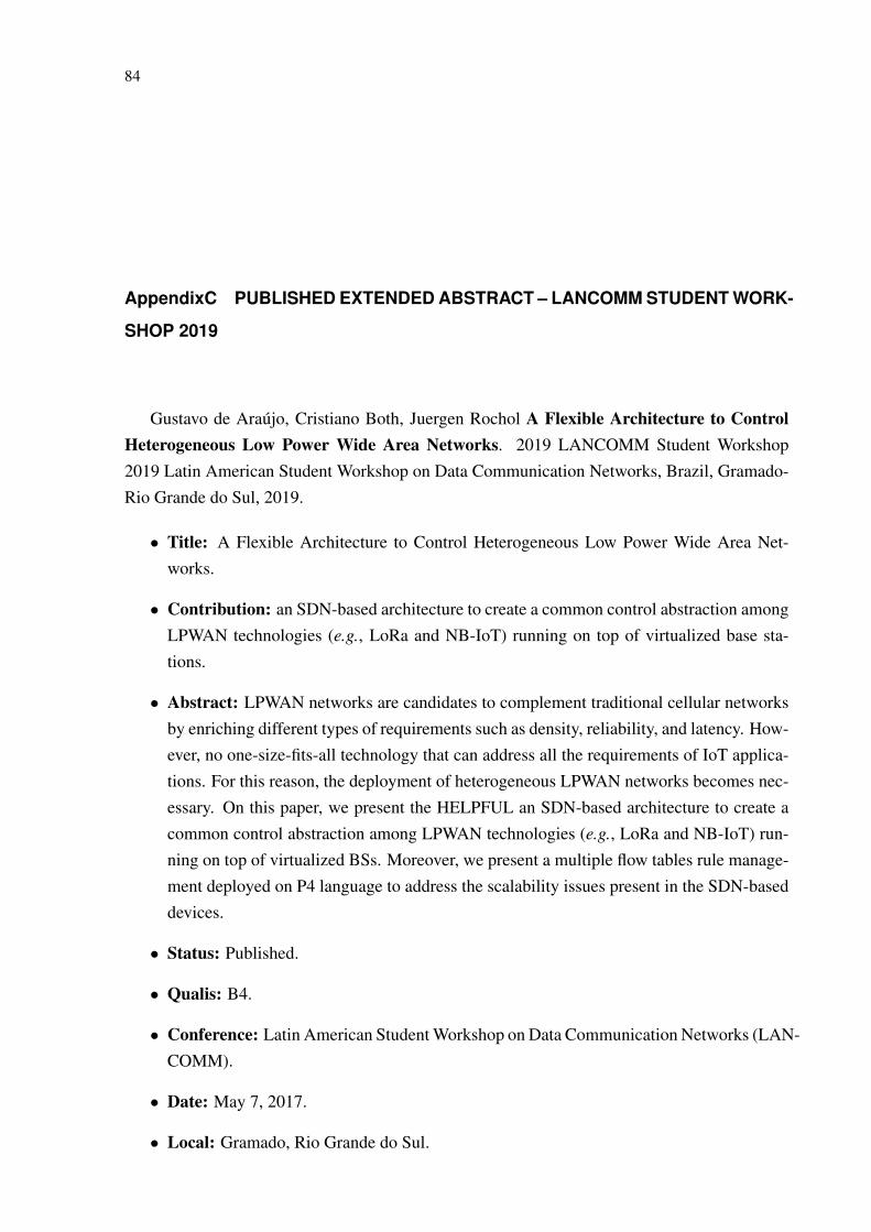
84
AppendixC PUBLISHED EXTENDED ABSTRACT – LANCOMM STUDENT WORK-
SHOP 2019
Gustavo de Araújo, Cristiano Both, Juergen Rochol A Flexible Architecture to ControlHeterogeneous Low Power Wide Area Networks. 2019 LANCOMM Student Workshop2019 Latin American Student Workshop on Data Communication Networks, Brazil, Gramado-Rio Grande do Sul, 2019.
• Title: A Flexible Architecture to Control Heterogeneous Low Power Wide Area Net-works.
• Contribution: an SDN-based architecture to create a common control abstraction amongLPWAN technologies (e.g., LoRa and NB-IoT) running on top of virtualized base sta-tions.
• Abstract: LPWAN networks are candidates to complement traditional cellular networksby enriching different types of requirements such as density, reliability, and latency. How-ever, no one-size-fits-all technology that can address all the requirements of IoT applica-tions. For this reason, the deployment of heterogeneous LPWAN networks becomes nec-essary. On this paper, we present the HELPFUL an SDN-based architecture to create acommon control abstraction among LPWAN technologies (e.g., LoRa and NB-IoT) run-ning on top of virtualized BSs. Moreover, we present a multiple flow tables rule manage-ment deployed on P4 language to address the scalability issues present in the SDN-baseddevices.
• Status: Published.
• Qualis: B4.
• Conference: Latin American Student Workshop on Data Communication Networks (LAN-COMM).
• Date: May 7, 2017.
• Local: Gramado, Rio Grande do Sul.


A Flexible Architecture to Control HeterogeneousLow Power Wide Area Networks
Gustavo AraújoFederal University of Rio Grande
do Sul - UFRGS
Cristiano Bonato BothVale Do Rio Sinos University -
Unisinos
Juergen RocholFederal University of Rio Grande
do Sul - UFRGSABSTRACTLPWAN networks are candidates to complement traditionalcellular networks by enriching different types ofrequirements such as density, reliability, and latency.However, no one-size-fits-all technology that can addressall the requirements of IoT applications. For this reason,the deployment of heterogeneous LPWAN networksbecomes necessary. On this paper, we present the HELPFULan SDN-based architecture to create a common controlabstraction among LPWAN technologies (e.g., LoRa andNB-IoT) running on top of virtualized BSs. Moreover, wepresent a multiple flow tables rule management deployedon P4 language to address the scalability issues present inthe SDN-based devices.
1 INTRODUCTIONThe coexistence of heterogeneous LPWAN technologiesis desired to exploit the best features each technology hasto offer, addressing multiple communication requirementsindependently. On the other hand, deploying and operatingseveral independent heterogeneous networks, eachsupporting a limited number of IoT devices, becomeschallenging. Firstly, current LPWAN technologies havenot been designed to coexist with each other, as eachLPWAN implements individual control protocols leading touncoordinated wireless access. Secondly, the assumptionof multiple wireless access technologies in the traditionalarchitecture of the cellular network would lead to prohibitivedeployment costs of transmitters cells.Aiming to cope with the deployment cost challenge,
virtualization of Base Stations (BS) have already proposedas a solution to reduce CAPEX of cellular networksthrough infrastructure sharing [4]. The problem is thatvirtualization adds the need for new control access tothe infrastructure, on uncontrolled access to the spectrumused by the LPWAN. Software-Defined Networking (SDN)provides a powerful approach by creating a programmable,dynamic, and flexible architecture that allows the abstractionfrom traditional hardware-based protocol implementationsinto a software-based network controller. In this sense,some studies have applied the SDN paradigm to providea programmable network to IoT applications [5] [3] [1][2]. However, these works do not take into account the
limited capacity of SDN-based forwarding devices to storethe forwarding rules. The tables have a limited rule storagecapacity, which is several orders of magnitude smaller thanthat required for the operation of certain types of network,including LPWAN. This problem becomes worse whenapplied in LPWAN environments where a massive amountof end-nodes in a network making it necessary to managethe rules of the flow tables.
In this work, we propose HELPFUL (Flexible Architectureto control Heterogeneous Low Power Wide Area Network)to enable heterogeneous LPWAN networks to coexistwhit scalability guarantees. HELPFUL is an SDN-basedarchitecture to create a common control abstractionamong LPWAN technologies running on top of virtualizedBSs. Furthermore, we present multiple flow tables rulemanagement to address the scalability issues present in theSDN-based devices. As the main contribution of this paper,we define an architecture that adds an abstraction layerthat can translate the heterogeneous control protocols toa homogeneous set of messages. The technology-specificcontrol could be unified into a single cross-technologycontroller, enabling infrastructure and spectrum access tobe harmonized. For validation of HELPFUL, we prototypeusing the P4 language that allows having programmabilityof both control and forwarding plane.
2 RELATED WORKLPWAN technologies are not designed to coexist with eachother. In the literature are found some studies that apply SDNconcepts for coexistence between different technologies. Inthis sense, Gallo et al., [3] propose the use of gatewaysthat can be reprogrammed by a controller according tothe network overhead. However, this proposal does notallow a gateway simultaneously operate with more thanone technologies at the time. Other investigations adopt theOpenFlow protocol for simultaneous operation with morethan one network technology [5] [1] [2]. However, thesestudies do not take into account the limited storage capacityof the flow tables. To better use the storage capacity of thetables it is needed to apply some management strategiesis necessary. In the literature, there are four main ways ofmanagement: substitution, flow aggregation, caching, andmultiple flow tables [6]. In our work, we are using the
1
86

LANCOMM Student Workshop, 2019 Araújo.et al.
multiple flow tables strategies because of the cost-benefitcompared to the other strategies.
3 HELPFULIn this section, we introduce the HELPFUL conceptualarchitecture and its main components. On its essentiallythe HELPFUL is an SDN-based architecture divided into fourplanes: forward, controller, application, and management.We implement our architecture using the P4 language. Thelight blue boxes represent the planes in Figure
Figure 1: HELPFUL ArchitectureHELPFUL
Management
HEL
PFU
LFo
rwar
dH
ELP
FUL
Con
trol
ler
HEL
PFU
LA
pplic
a�on
Southbound API
Northbound API
Tran
slat
or
NB-IoT LoRA
AbstractPacket
AbstractPacket
Info Info
Packet Factory
NB-IoTLoRA
AbstractPacket
AbstractPacket
Control Control
Packet Dissector
Dyn
amic
Con
trol
Tab
les
Con
trol
Tab
les
ChannelSelec�on Table
Rx WindowTable
ForwardingTable
Table N
Pipeline Control
Sta�s�csMonitor
ControlRules/Ac�ons
Resource Monitor
Man
agem
ent A
PI
AddNew
TableManagement
TranslateManagement
ControllerManagement
Applica�onManagement
Applica�on N
LoRa
NB-IoT
NB-IoT
NB-IoT
LoRA
LoRa
Associa�onControl
Inter-cellCoordena�on
The HELPFUL Forward plane is composed of networkdevices interconnected through an LPWAN technology(e.g., LoRaWAN, NB-IoT) or wired network technology. Onour architecture the network devices are divided into twocomponents: (i) the Translator and (ii) the Dynamic ControlTables. The Translator is responsible for creating a commoncontrol abstraction among LPWAN technologies by wrappedthe information from a technology-specific packet andgenerated a new and abstract packet that can be submittedand processed by the Dynamic Control Tables. This Controlis responsible for storing the rules that define the networkfunctions. Each network function has a correspondingtable on the Control Tables (e.g., forwarding table, channelselection table).Each table implements its own rules with his respective
match fields and actions (e.g., forward to specific ports, drop,forward to the controller, and rewrite some header). Onthis model, each table represents a network function and
has its own set of header fields for identifying a package,actions to be applied and, rules counters. Further, each tableimplements just the necessary to make his function andavoiding consuming resources unnecessarily.Vertically to the other planes, we have the HELPFUL
Management. This plane has four components: (i)Application Management, (ii) Controller Management,(iii) Table Management and (iv) Translate Management.The Application Management is responsible for adding,removing, and get information for the network administratorabout the applications that are running on the HELPFULapplication. The Controller Management is responsible forinforming the HELPFUL Controller the definitions of therules and statistics of the tables. Table Management has thefunction of install and removes tables from the DynamicControl Tables. The Translate Management configure thetranslator notifying how to wrapped a technology-specificand created an abstract packet that will be processed by theDynamic Control Tables.
4 FUTUREWORKAs future work, we are concluding the implementation ofthe HELPFUL to carry out experimentation, and we canmeasure its benefits correctly. We will evaluate our rulemanagement solution in the multiple flow table comparingto the existing forms of management of flow aggregation,caching, and eviction. In our preliminary results, it is alreadypossible to identify that the type of control by multiple tablesis the one that has the best cost-benefit compared to theaggregation of flows.
REFERENCES[1] Michael Baddeley, Reza Nejabati, George Oikonomou, Mahesh
Sooriyabandara, and Dimitra Simeonidou. 2018. Evolving SDN forLow-Power IoT Networks. 2018 4th IEEE Conference on NetworkSoftwarization and Workshops, NetSoft 2018 (2018).
[2] Samaresh Bera, Sudip Misra, Sanku Kumar Roy, and Mohammad S.Obaidat. 2018. Soft-WSN: Software-defined WSN management systemfor IoT applications. IEEE Systems Journal (2018).
[3] Pierluigi Gallo, Katarzyna Kosek-Szott, Szymon Szott, and IleniaTinnirello. 2016. SDN@home: A method for controlling future wirelesshome networks. IEEE Communications Magazine (2016).
[4] Maicon Kist, Juergen Rochol, Luiz A Dasilva, and Cristiano BonatoBoth. 2018. SDR Virtualization in Future Mobile Networks : EnablingMulti-Programmable Air-Interfaces. 2018 IEEE International Conferenceon Communications (ICC) (2018).
[5] Tie Luo, Hwee-pink Tan, and Tony Q S Quek. 2012. SensorOpenFlow : Enabling Software-DefinedWireless Sensor Networks. IEEECommunications Letters (2012).
[6] Xuan NamNguyen, Damien Saucez, Chadi Barakat, and Thierry Turletti.2016. Rules Placement Problem in OpenFlow Networks: A Survey. IEEECommunications Surveys and Tutorials (2016).
2
87

88
AppendixD JOURNAL OF NETWORK AND COMPUTER APPLICATIONS 2019
Gustavo de Araújo, Rodolfo Antunes, Cristiano Both, Juergen Rochol HELPFUL: FlexibleArchitecture to Control Heterogeneous Low Power Wide Area Networks. 2019 Journal ofNetwork and Computer Applications.
• Title: HELPFUL: Flexible Architecture to Control Heterogeneous Low Power Wide AreaNetworks
• Contribution: an SDN-based architecture to create a common control abstraction amongLPWAN technologies (e.g., LoRa and NB-IoT) running on top of virtualized base sta-tions.
• Abstract: Low Power Wide Area Networks (LPWAN) are candidates to coexist with tra-ditional cellular networks by coping with different types of requirements such as density,reliability, and latency. However, there is no one-size-fits-all technology that can addressall the needs of IoT applications. For this reason, the integration of heterogeneous LP-WAN becomes necessary. This article presents the HELPFUL, an SDN-based architec-ture that creates a common control abstraction among LPWAN technologies (e.g., LoRa,NB-IoT) running on top of virtualized base stations. We also discuss four rule manage-ment strategies for use with HELPFUL, providing support for single and multiple flowtables. We evaluate our proposal with a series of experiments with a prototype developedusing the P4 language. Results show which HELPFUL is flexible enough to change themanagement strategy to the best fit with the network demands. Consequently, it can re-duce the number of messages on the control channel exchanged between the Controllerand Gateways. Finally, HELPFUL adds minimal overhead to network performance, re-gardless of the rule management strategy chosen.
• Status: To apper.
• Qualis: A2.
• Conference: Journal of Network and Computer Applications (JNCA).
• URL: <https://www.journals.elsevier.com/journal-of-network-and-computer-applications>.