hello. wepresentourworksubdivisionnext event ...wjarosz/publications/koerner16... · college, peter...
TRANSCRIPT
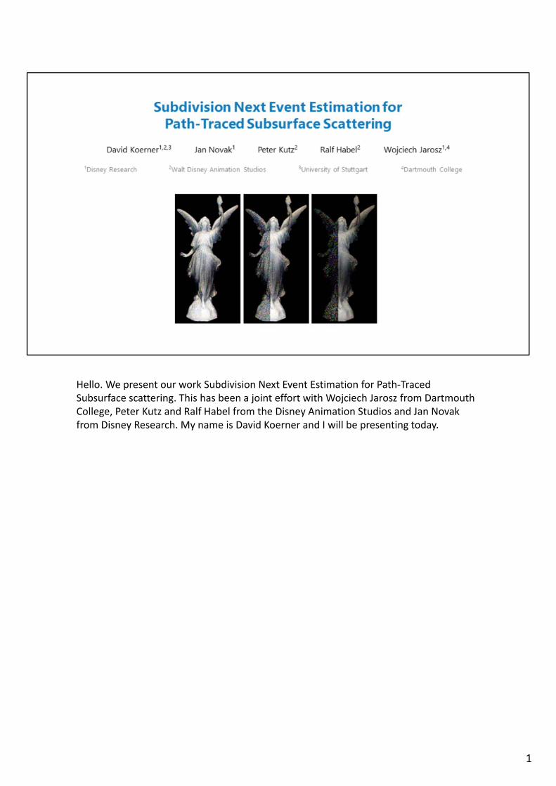
Hello. We present our work Subdivision Next Event Estimation for Path‐TracedSubsurface scattering. This has been a joint effort with Wojciech Jarosz from DartmouthCollege, Peter Kutz and Ralf Habel from the Disney Animation Studios and Jan Novak from Disney Research. My name is David Koerner and I will be presenting today.
1
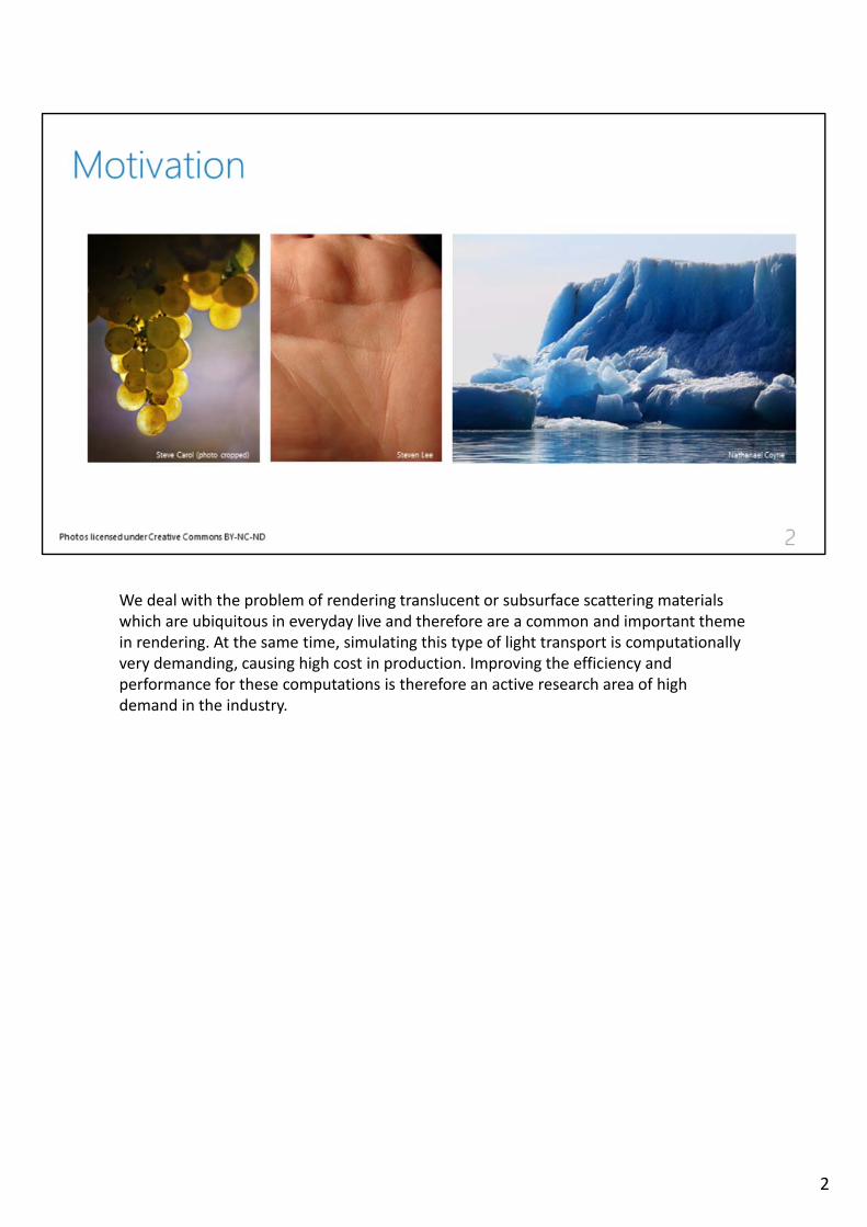
We deal with the problem of rendering translucent or subsurface scattering materialswhich are ubiquitous in everyday live and therefore are a common and important themein rendering. At the same time, simulating this type of light transport is computationallyvery demanding, causing high cost in production. Improving the efficiency andperformance for these computations is therefore an active research area of high demand in the industry.
2
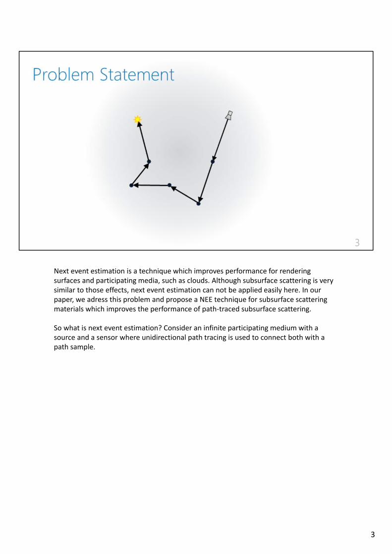
Next event estimation is a technique which improves performance for renderingsurfaces and participating media, such as clouds. Although subsurface scattering is verysimilar to those effects, next event estimation can not be applied easily here. In ourpaper, we adress this problem and propose a NEE technique for subsurface scatteringmaterials which improves the performance of path‐traced subsurface scattering.
So what is next event estimation? Consider an infinite participating medium with a source and a sensor where unidirectional path tracing is used to connect both with a path sample.
3
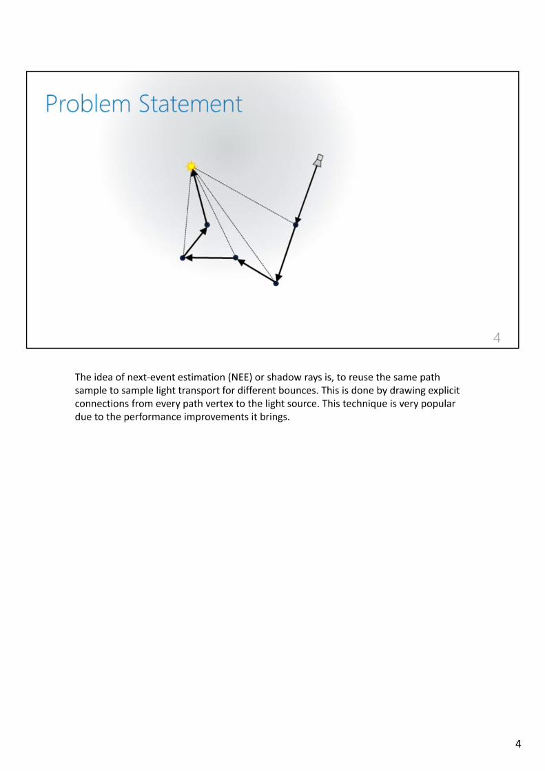
The idea of next‐event estimation (NEE) or shadow rays is, to reuse the same pathsample to sample light transport for different bounces. This is done by drawing explicit connections from every path vertex to the light source. This technique is very populardue to the performance improvements it brings.
4
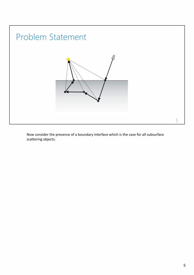
Now consider the presence of a boundary interface which is the case for all subsurfacescattering objects.
5
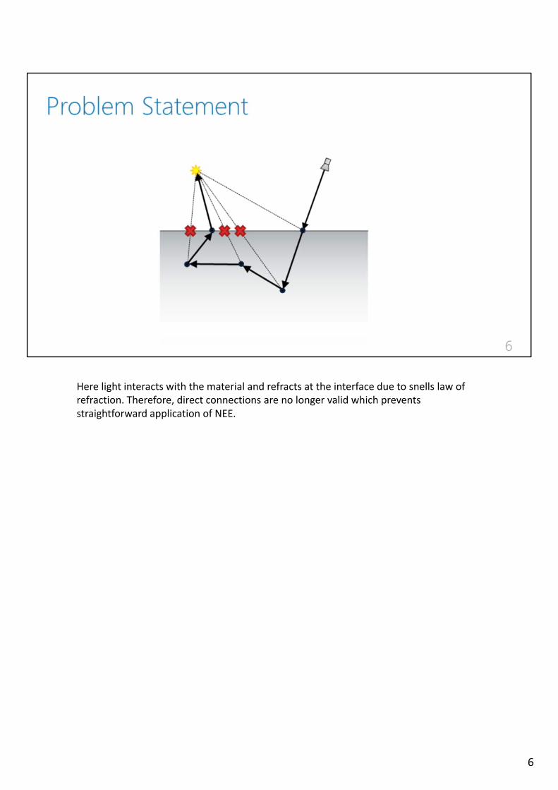
Here light interacts with the material and refracts at the interface due to snells law ofrefraction. Therefore, direct connections are no longer valid which prevents straightforward application of NEE.
6
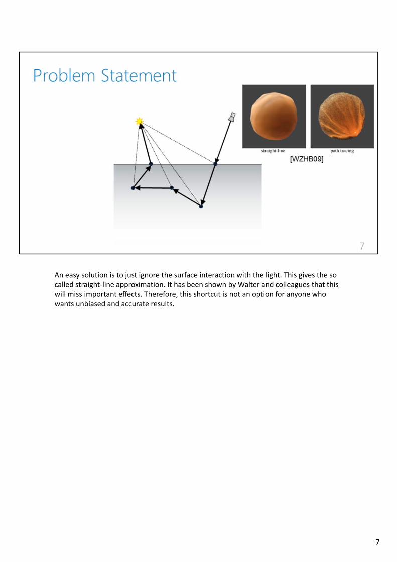
An easy solution is to just ignore the surface interaction with the light. This gives the so called straight‐line approximation. It has been shown by Walter and colleagues that thiswill miss important effects. Therefore, this shortcut is not an option for anyone whowants unbiased and accurate results.
7

This problem of doing NEE through interfaces has been addressed in the past and still appears to be an active research topic.
8
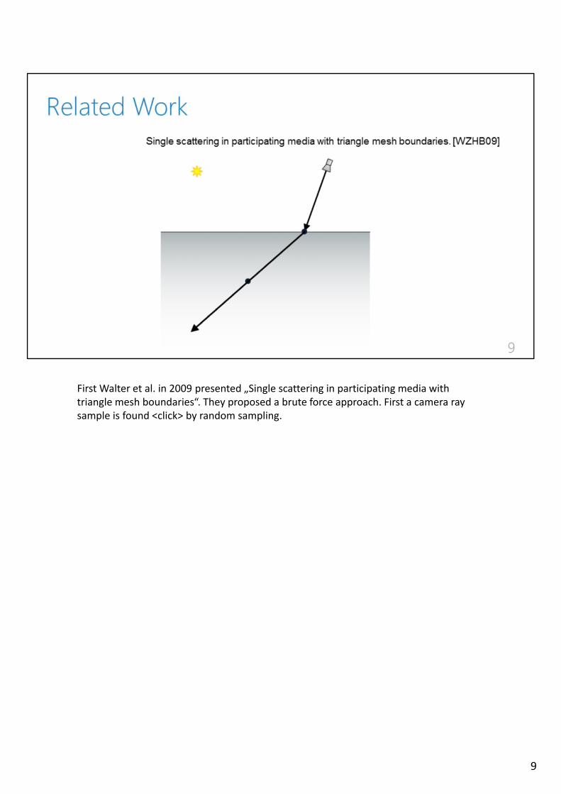
First Walter et al. in 2009 presented „Single scattering in participating media withtriangle mesh boundaries“. They proposed a brute force approach. First a camera raysample is found <click> by random sampling.
9
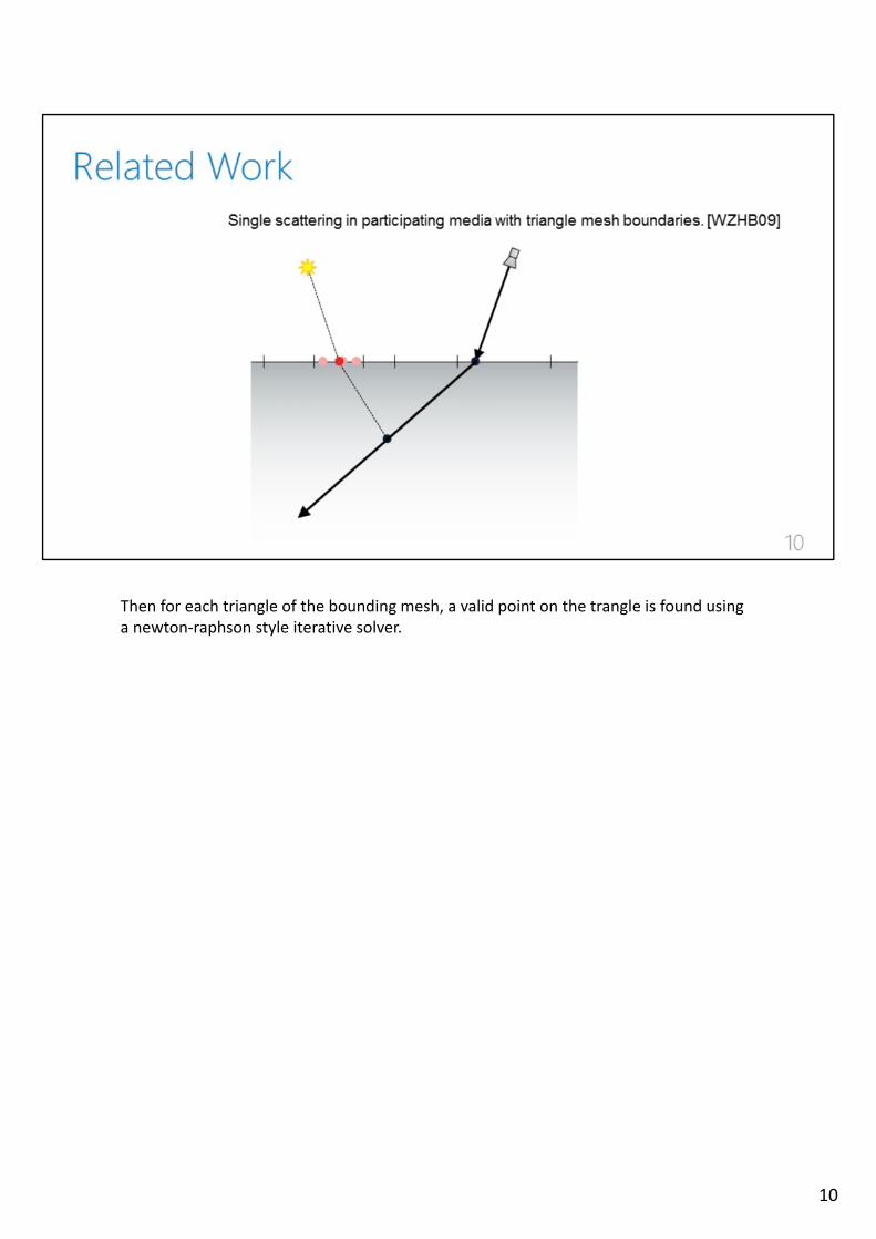
Then for each triangle of the bounding mesh, a valid point on the trangle is found usinga newton‐raphson style iterative solver.
10
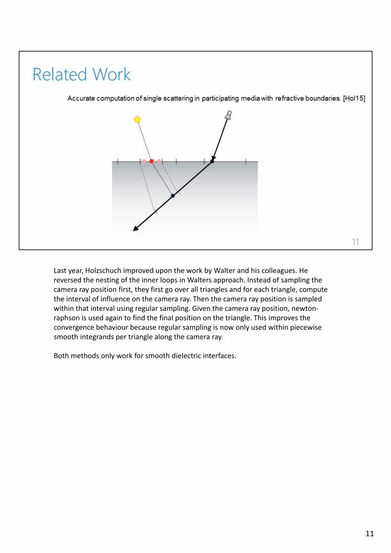
Last year, Holzschuch improved upon the work by Walter and his colleagues. He reversed the nesting of the inner loops in Walters approach. Instead of sampling thecamera ray position first, they first go over all triangles and for each triangle, computethe interval of influence on the camera ray. Then the camera ray position is sampledwithin that interval using regular sampling. Given the camera ray position, newton‐raphson is used again to find the final position on the triangle. This improves theconvergence behaviour because regular sampling is now only used within piecewisesmooth integrands per triangle along the camera ray.
Both methods only work for smooth dielectric interfaces.
11
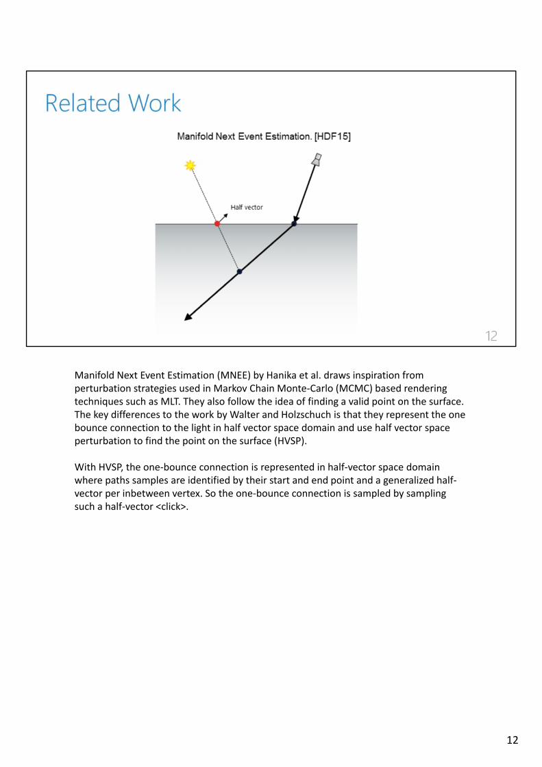
Manifold Next Event Estimation (MNEE) by Hanika et al. draws inspiration fromperturbation strategies used in Markov Chain Monte‐Carlo (MCMC) based renderingtechniques such as MLT. They also follow the idea of finding a valid point on the surface. The key differences to the work by Walter and Holzschuch is that they represent the onebounce connection to the light in half vector space domain and use half vector spaceperturbation to find the point on the surface (HVSP).
With HVSP, the one‐bounce connection is represented in half‐vector space domainwhere paths samples are identified by their start and end point and a generalized half‐vector per inbetween vertex. So the one‐bounce connection is sampled by samplingsuch a half‐vector <click>.
12
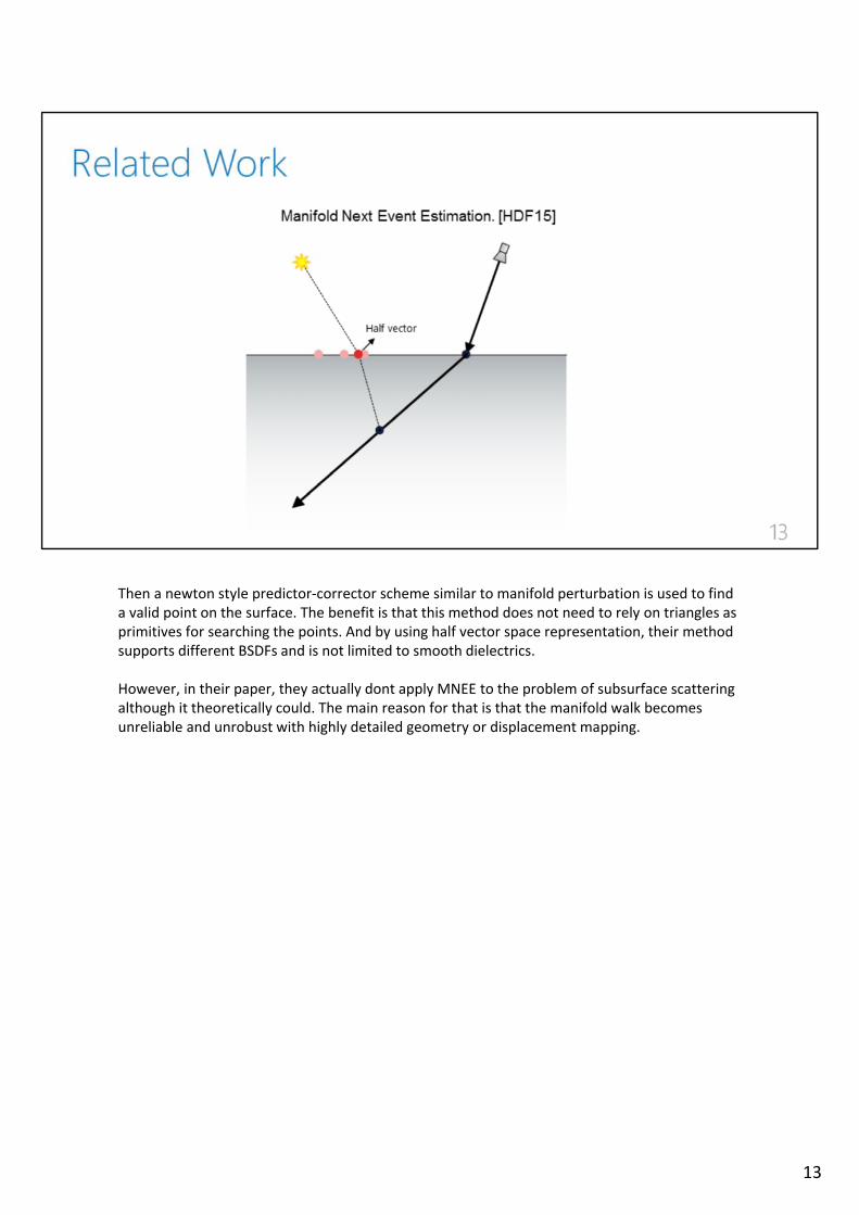
Then a newton style predictor‐corrector scheme similar to manifold perturbation is used to find a valid point on the surface. The benefit is that this method does not need to rely on triangles asprimitives for searching the points. And by using half vector space representation, their methodsupports different BSDFs and is not limited to smooth dielectrics.
However, in their paper, they actually dont apply MNEE to the problem of subsurface scatteringalthough it theoretically could. The main reason for that is that the manifold walk becomesunreliable and unrobust with highly detailed geometry or displacement mapping.
13
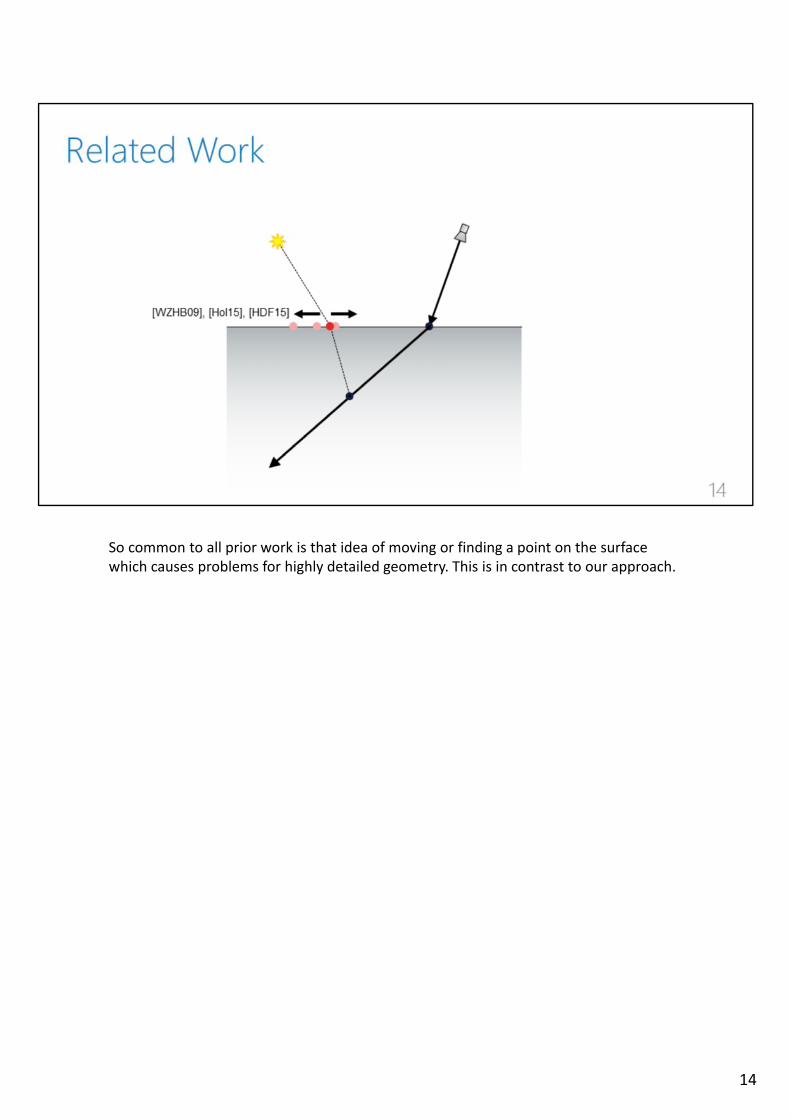
So common to all prior work is that idea of moving or finding a point on the surfacewhich causes problems for highly detailed geometry. This is in contrast to our approach.
14
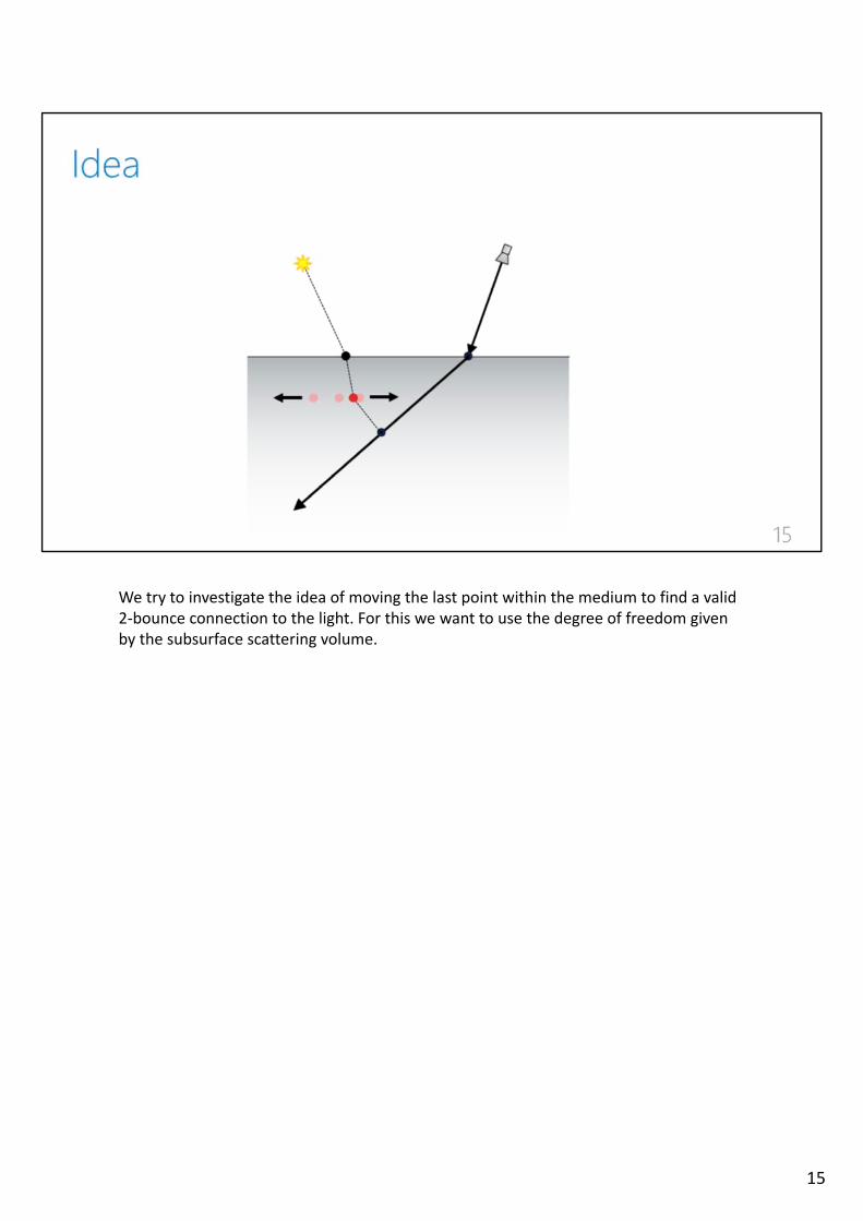
We try to investigate the idea of moving the last point within the medium to find a valid 2‐bounce connection to the light. For this we want to use the degree of freedom givenby the subsurface scattering volume.
15
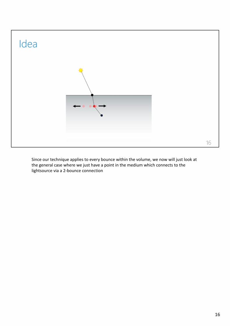
Since our technique applies to every bounce within the volume, we now will just look at the general case where we just have a point in the medium which connects to the lightsource via a 2‐bounce connection
16
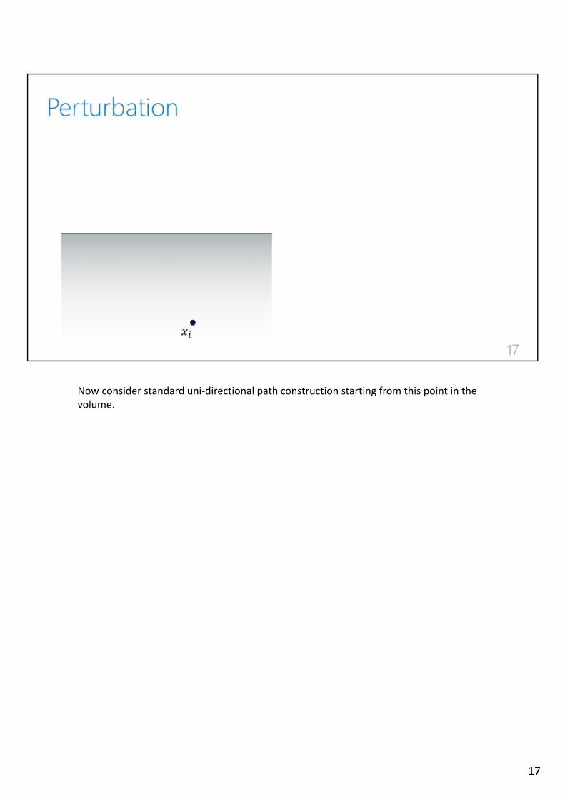
Now consider standard uni‐directional path construction starting from this point in thevolume.
17
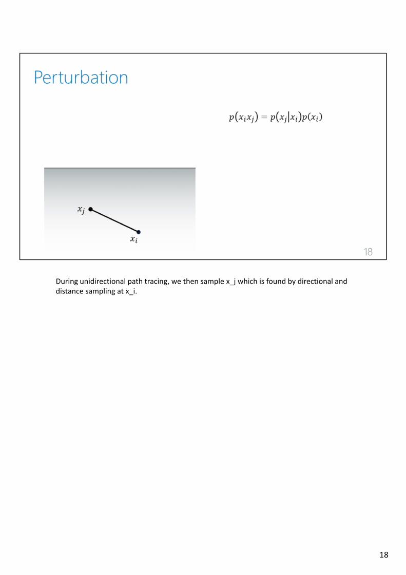
During unidirectional path tracing, we then sample x_j which is found by directional and distance sampling at x_i.
18
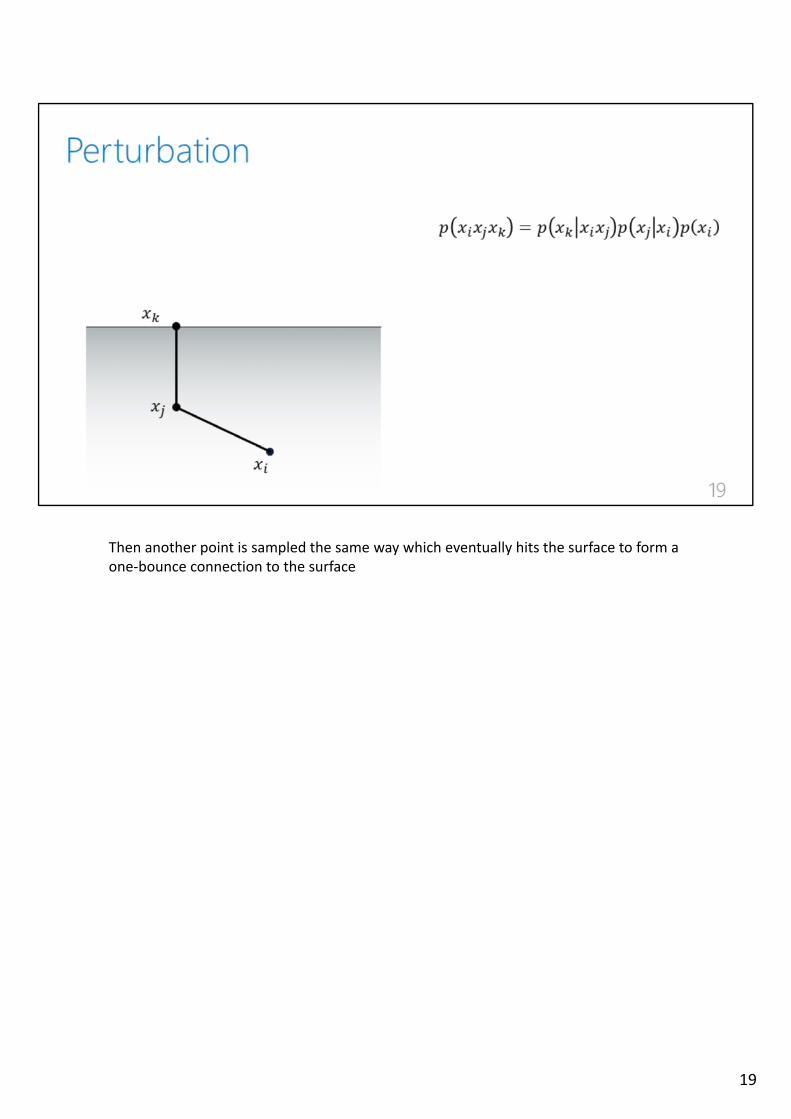
Then another point is sampled the same way which eventually hits the surface to form a one‐bounce connection to the surface
19
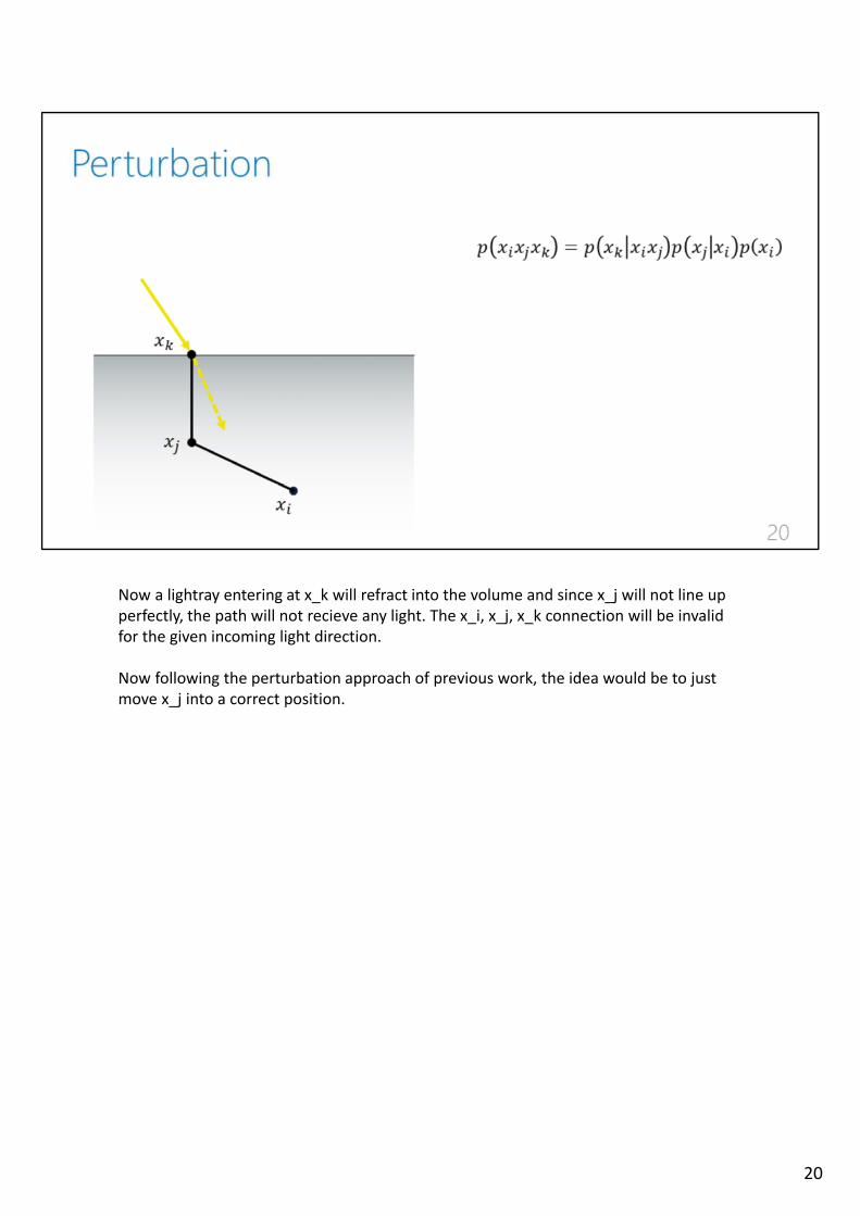
Now a lightray entering at x_k will refract into the volume and since x_j will not line up perfectly, the path will not recieve any light. The x_i, x_j, x_k connection will be invalid for the given incoming light direction.
Now following the perturbation approach of previous work, the idea would be to just move x_j into a correct position.
20
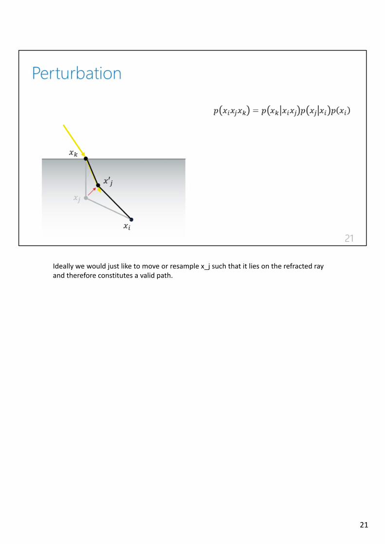
Ideally we would just like to move or resample x_j such that it lies on the refracted rayand therefore constitutes a valid path.
21
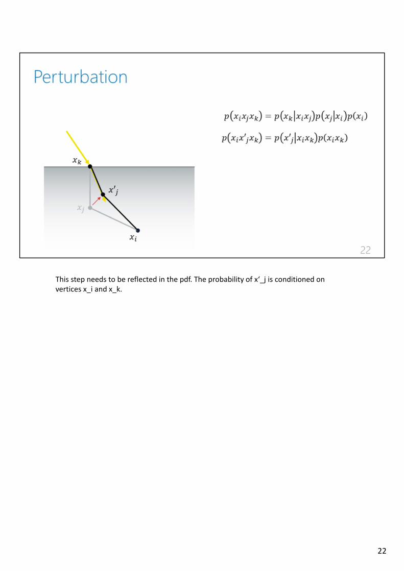
This step needs to be reflected in the pdf. The probability of x‘_j is conditioned on vertices x_i and x_k.
22
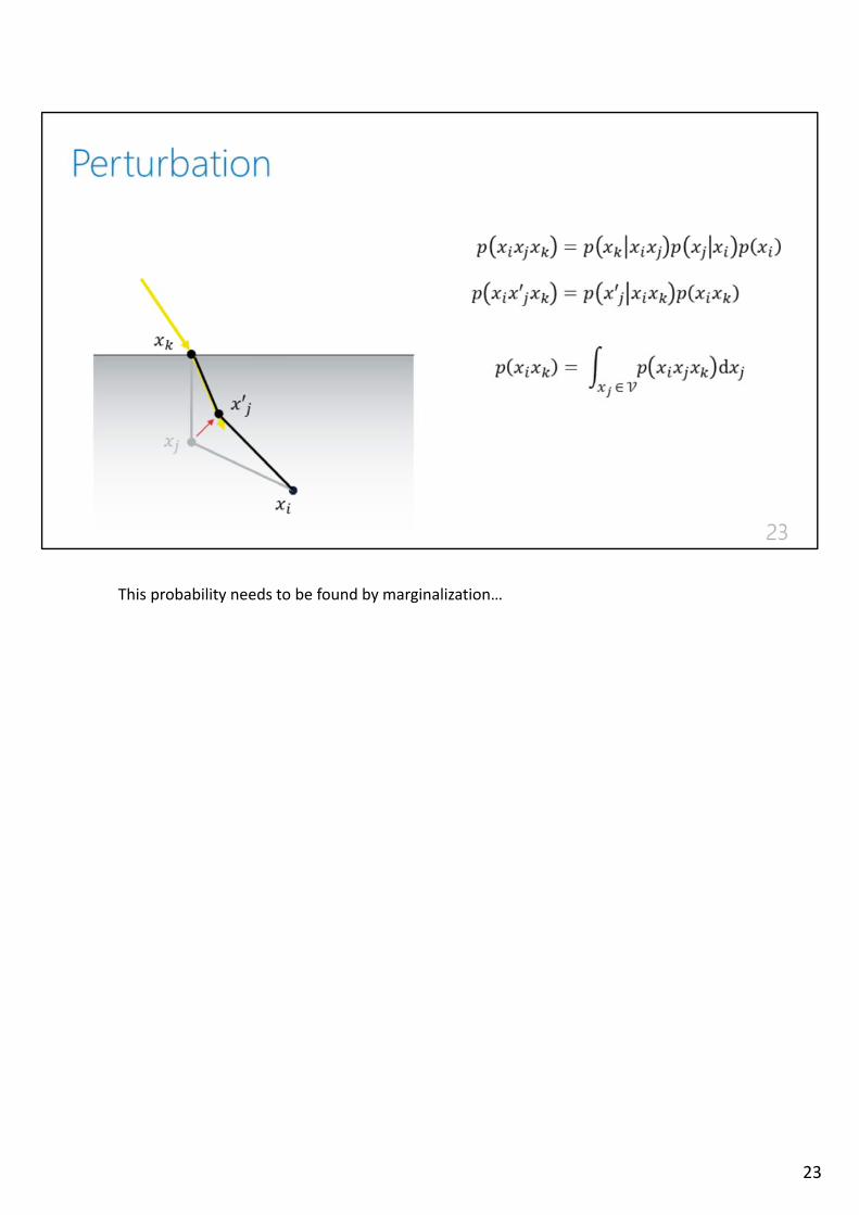
This probability needs to be found by marginalization…
23
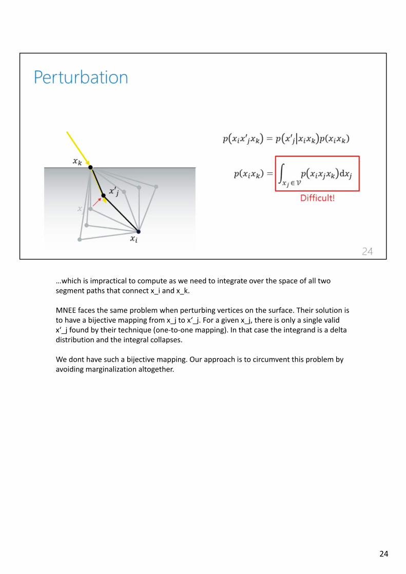
…which is impractical to compute as we need to integrate over the space of all two segment paths that connect x_i and x_k.
MNEE faces the same problem when perturbing vertices on the surface. Their solution is to have a bijective mapping from x_j to x‘_j. For a given x_j, there is only a single valid x‘_j found by their technique (one‐to‐one mapping). In that case the integrand is a deltadistribution and the integral collapses.
We dont have such a bijective mapping. Our approach is to circumvent this problem byavoiding marginalization altogether.
24
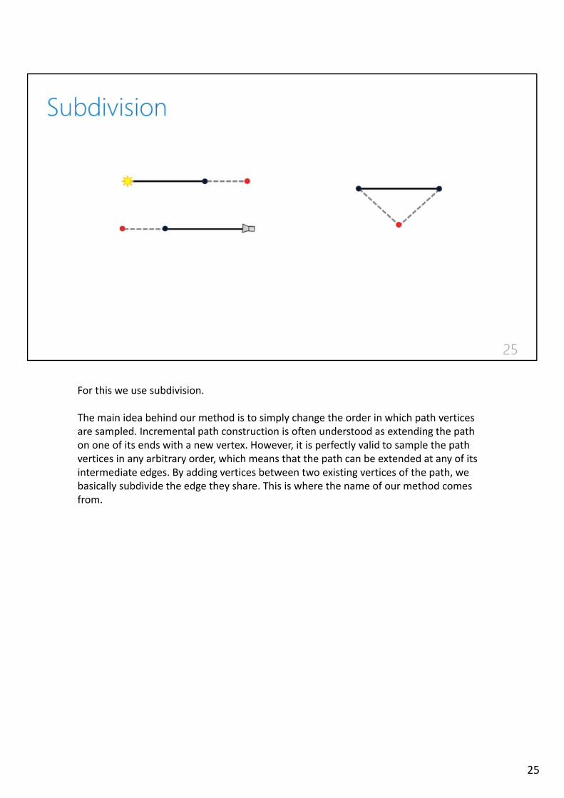
For this we use subdivision.
The main idea behind our method is to simply change the order in which path verticesare sampled. Incremental path construction is often understood as extending the pathon one of its ends with a new vertex. However, it is perfectly valid to sample the pathvertices in any arbitrary order, which means that the path can be extended at any of itsintermediate edges. By adding vertices between two existing vertices of the path, webasically subdivide the edge they share. This is where the name of our method comesfrom.
25
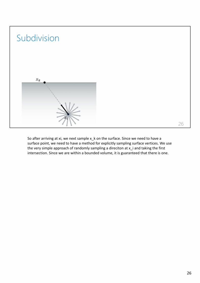
So after arriving at xi, we next sample x_k on the surface. Since we need to have a surface point, we need to have a method for explicitly sampling surface vertices. We usethe very simple approach of randomly sampling a direciton at x_i and taking the firstintersection. Since we are within a bounded volume, it is guaranteed that there is one.
26

THEN we sample x_j. Since we now know the surface point we can use informationabout the bsdf and incoming light when sampling x_j.
27
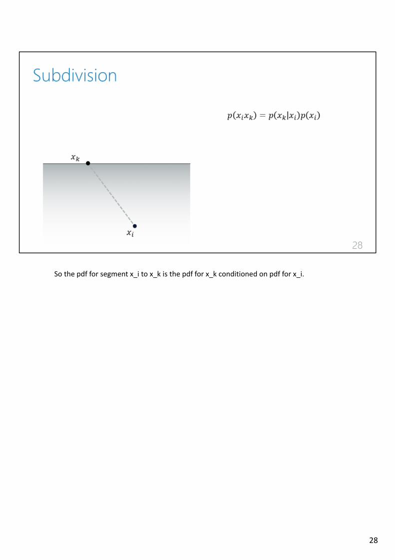
So the pdf for segment x_i to x_k is the pdf for x_k conditioned on pdf for x_i.
28
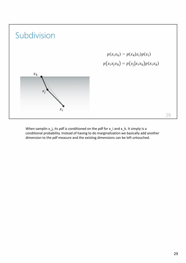
When samplin x_j, its pdf is conditioned on the pdf for x_i and x_k. It simply is a conditional probability. Instead of having to do marginalization we basically add anotherdimension to the pdf measure and the existing dimensions can be left untouched.
29
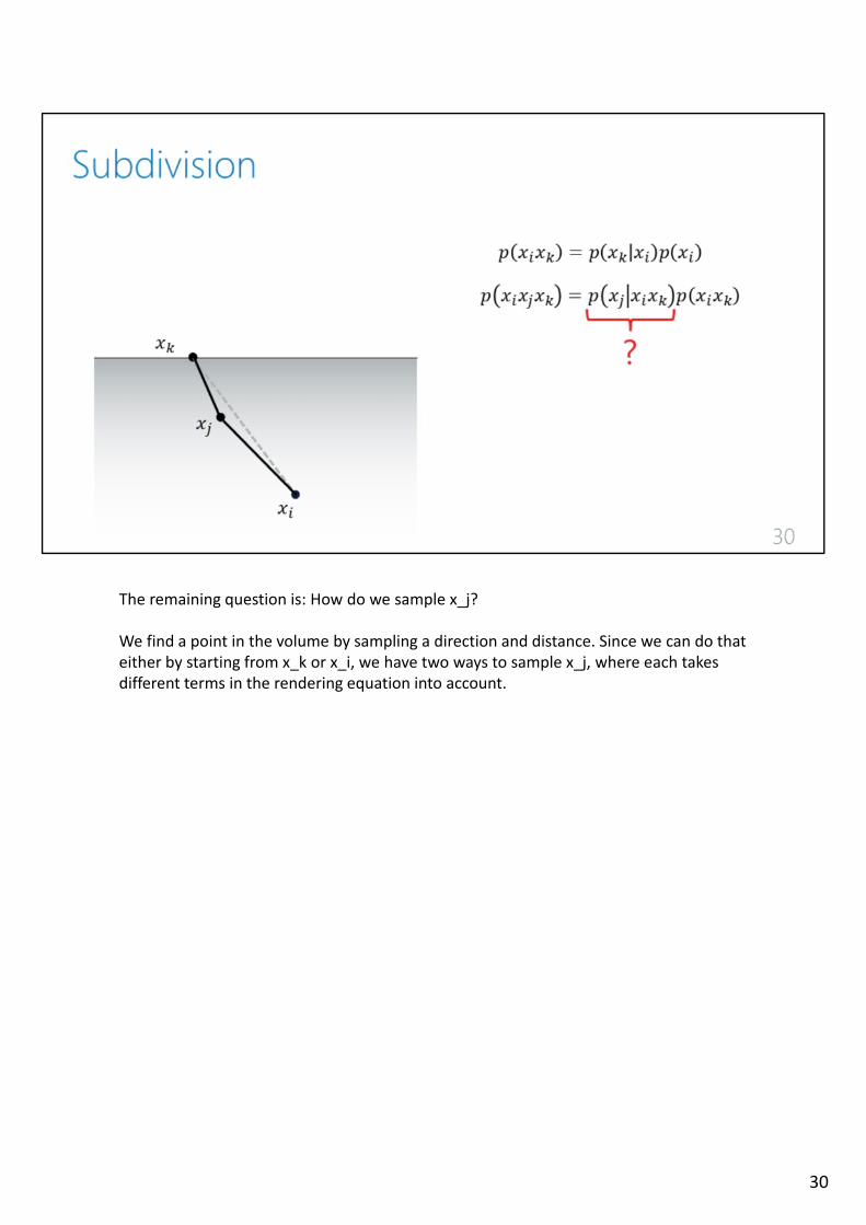
The remaining question is: How do we sample x_j?
We find a point in the volume by sampling a direction and distance. Since we can do thateither by starting from x_k or x_i, we have two ways to sample x_j, where each takesdifferent terms in the rendering equation into account.
30
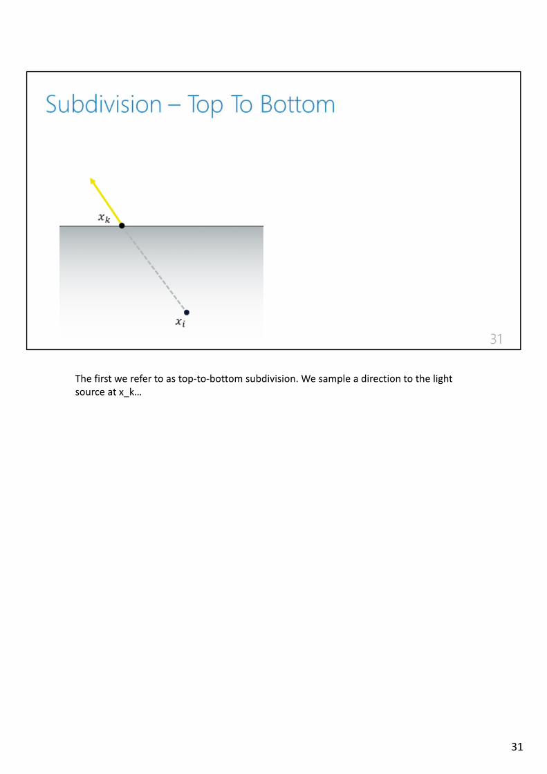
The first we refer to as top‐to‐bottom subdivision. We sample a direction to the light source at x_k…
31
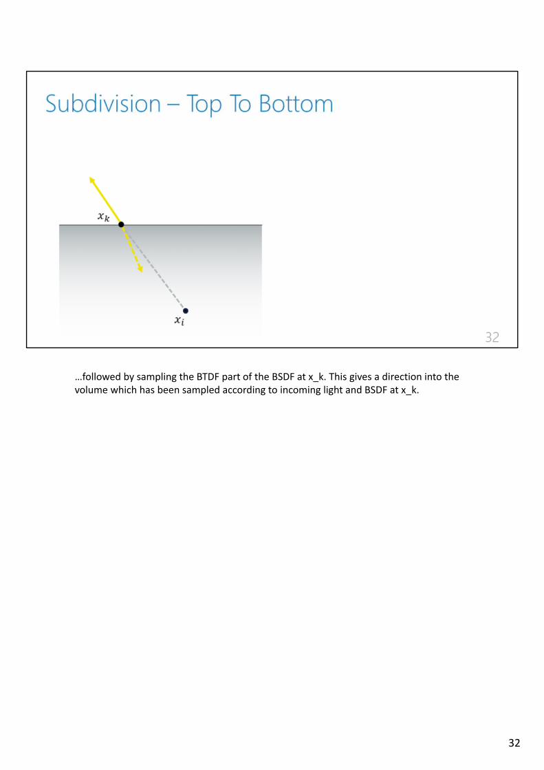
…followed by sampling the BTDF part of the BSDF at x_k. This gives a direction into thevolume which has been sampled according to incoming light and BSDF at x_k.
32
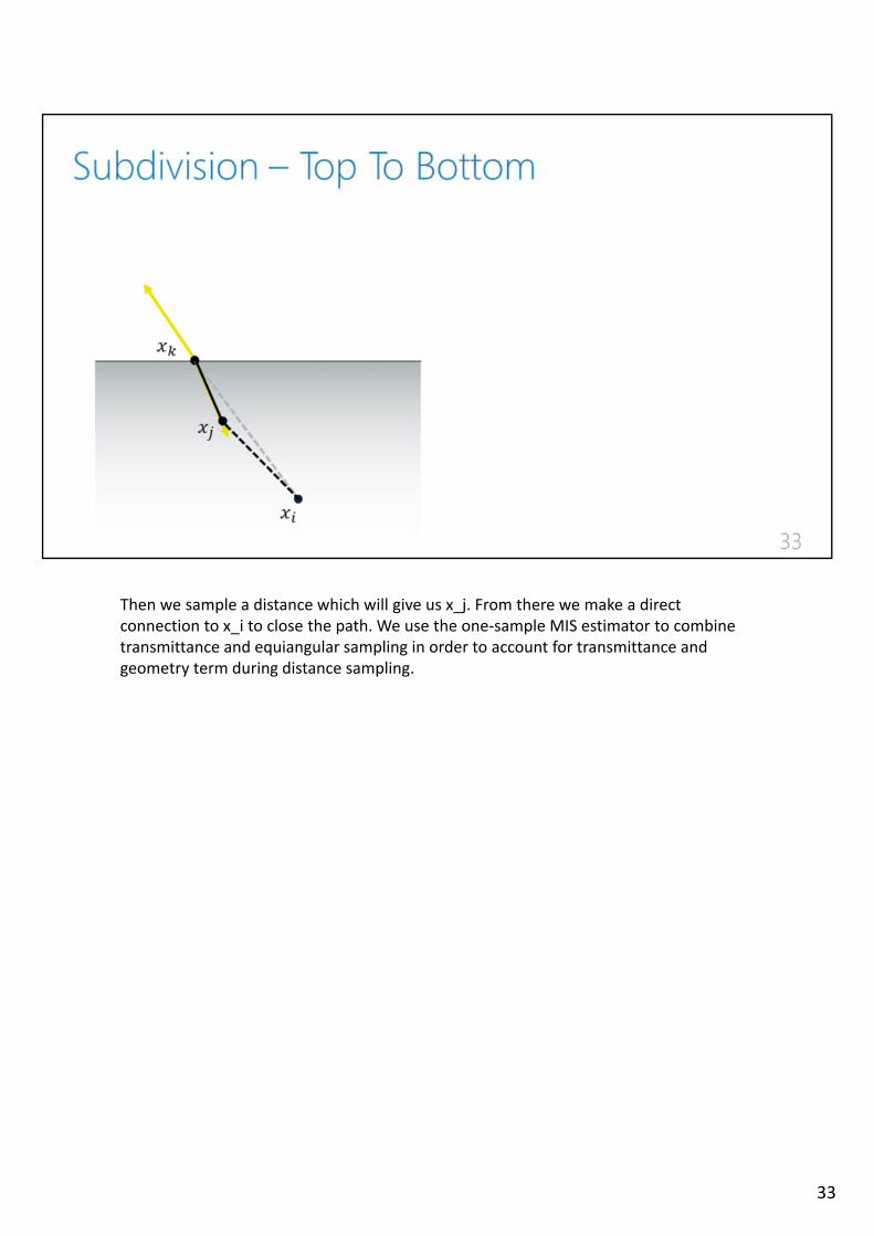
Then we sample a distance which will give us x_j. From there we make a directconnection to x_i to close the path. We use the one‐sample MIS estimator to combinetransmittance and equiangular sampling in order to account for transmittance andgeometry term during distance sampling.
33
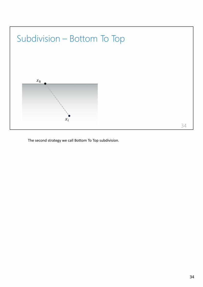
The second strategy we call Bottom To Top subdivision.
34
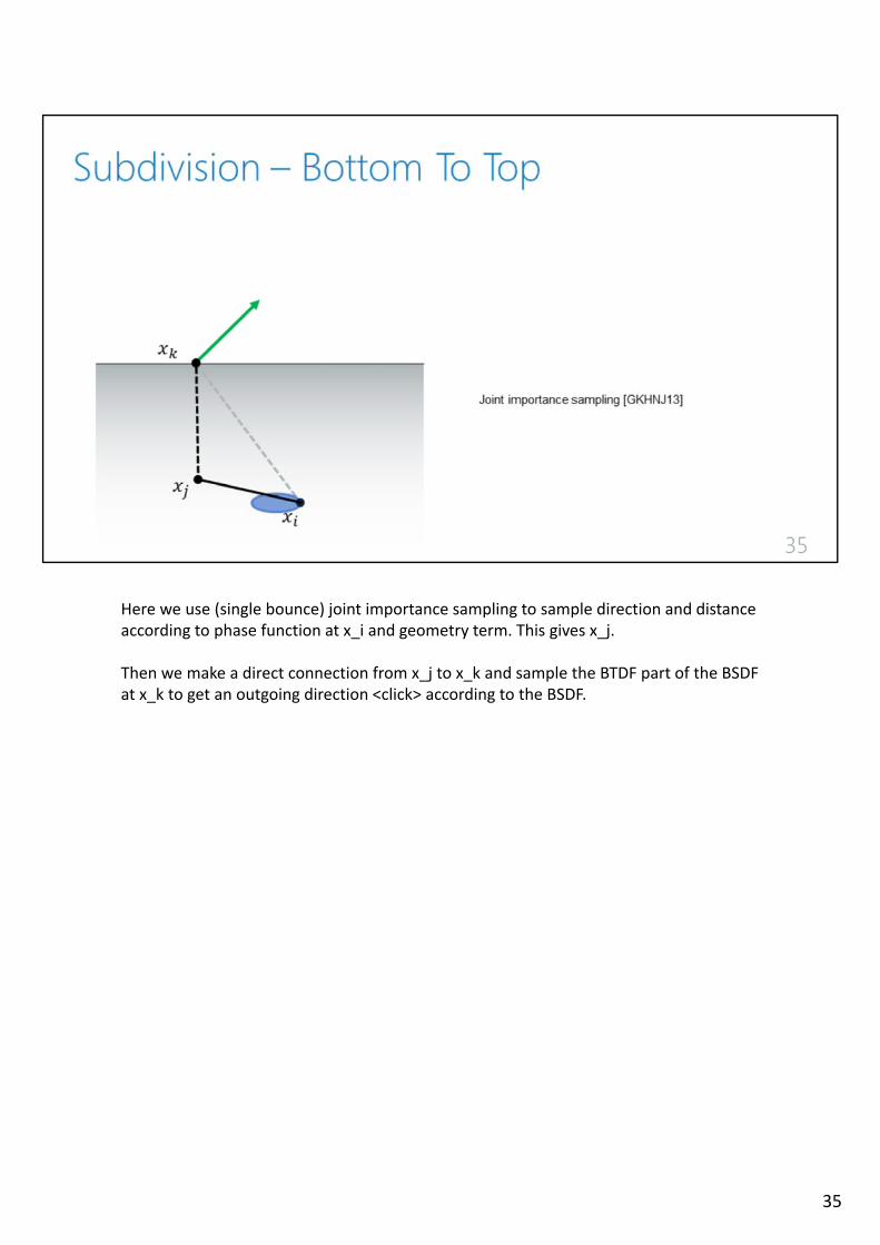
Here we use (single bounce) joint importance sampling to sample direction and distanceaccording to phase function at x_i and geometry term. This gives x_j.
Then we make a direct connection from x_j to x_k and sample the BTDF part of the BSDF at x_k to get an outgoing direction <click> according to the BSDF.
35
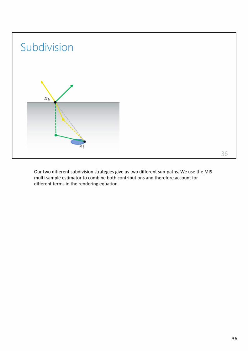
Our two different subdivision strategies give us two different sub‐paths. We use the MIS multi‐sample estimator to combine both contributions and therefore account fordifferent terms in the rendering equation.
36
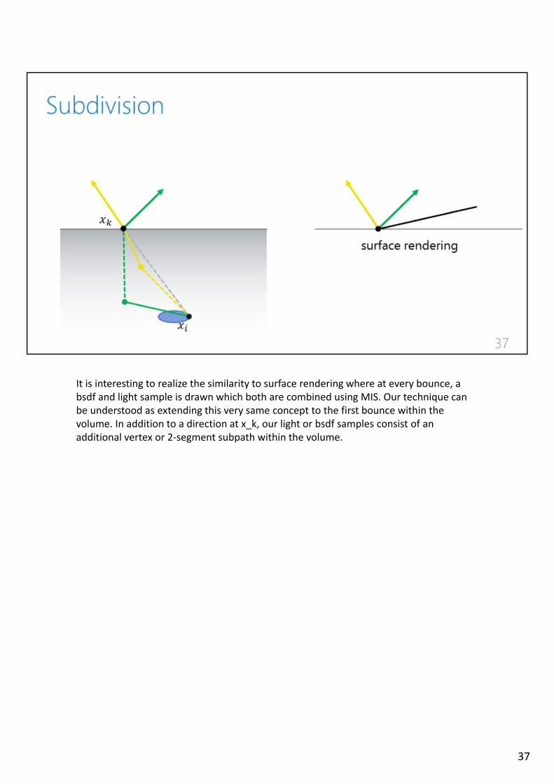
It is interesting to realize the similarity to surface rendering where at every bounce, a bsdf and light sample is drawn which both are combined using MIS. Our technique canbe understood as extending this very same concept to the first bounce within thevolume. In addition to a direction at x_k, our light or bsdf samples consist of an additional vertex or 2‐segment subpath within the volume.
37
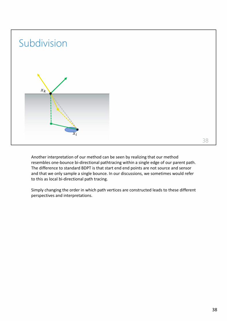
Another interpretation of our method can be seen by realizing that our methodresembles one‐bounce bi‐directional pathtracing within a single edge of our parent path. The difference to standard BDPT is that start end end points are not source and sensorand that we only sample a single bounce. In our discussions, we sometimes would referto this as local bi‐directional path tracing.
Simply changing the order in which path vertices are constructed leads to these different perspectives and interpretations.
38
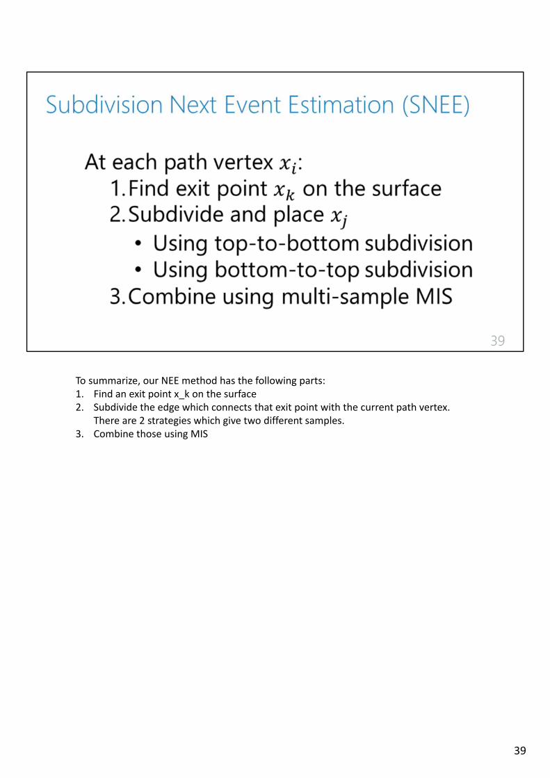
To summarize, our NEE method has the following parts:1. Find an exit point x_k on the surface2. Subdivide the edge which connects that exit point with the current path vertex.
There are 2 strategies which give two different samples.3. Combine those using MIS
39
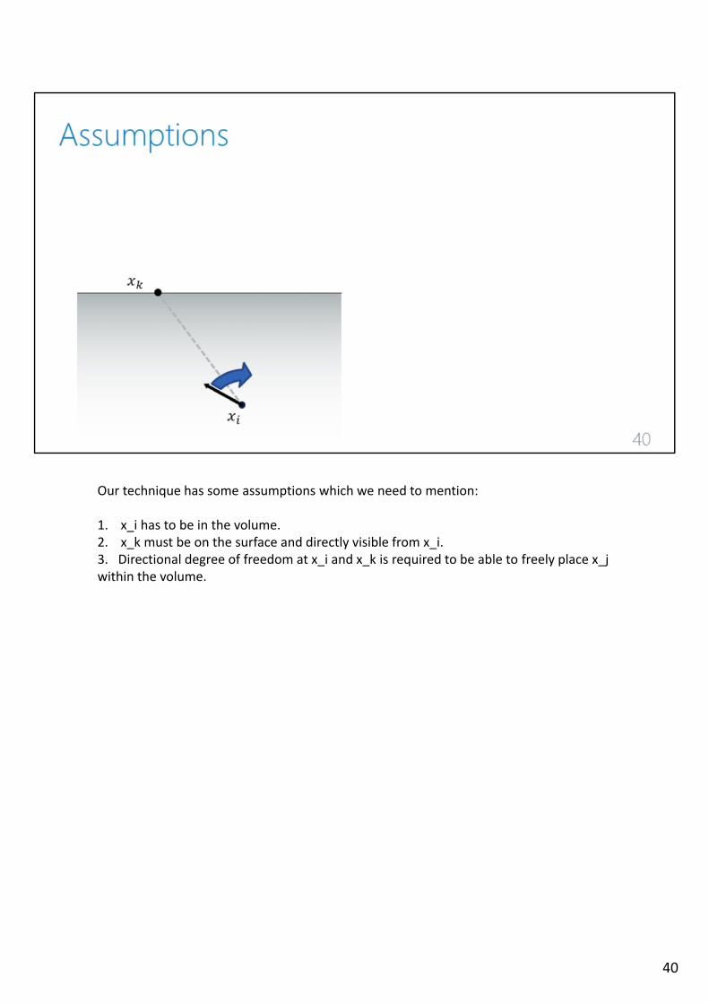
Our technique has some assumptions which we need to mention:
1. x_i has to be in the volume.2. x_k must be on the surface and directly visible from x_i.3. Directional degree of freedom at x_i and x_k is required to be able to freely place x_jwithin the volume.
40

Since our assumptions are not always met, our method does not sample all light transport.
41
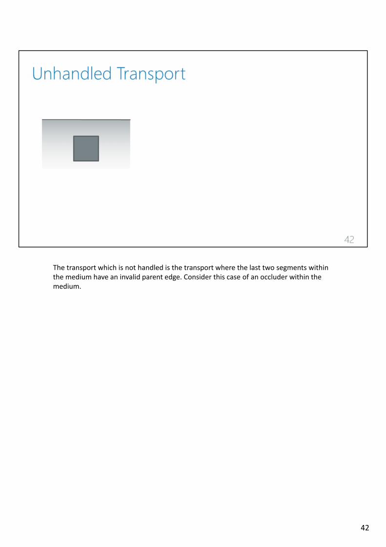
The transport which is not handled is the transport where the last two segments withinthe medium have an invalid parent edge. Consider this case of an occluder within themedium.
42
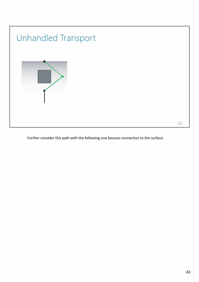
Further consider this path with the following one bounce connection to the surface.
43
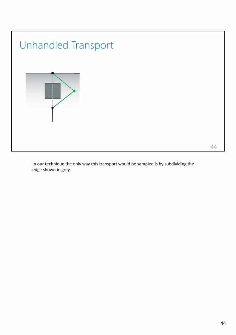
In our technique the only way this transport would be sampled is by subdividing theedge shown in grey.
44

However, this edge will never exist due to the way we currently sample the surfacepoints. Therefore it will never be subdivided and the shown transport would never besampled. A similar problem arises for parent edges on the flat surface. Those will neverbe sampled.
45
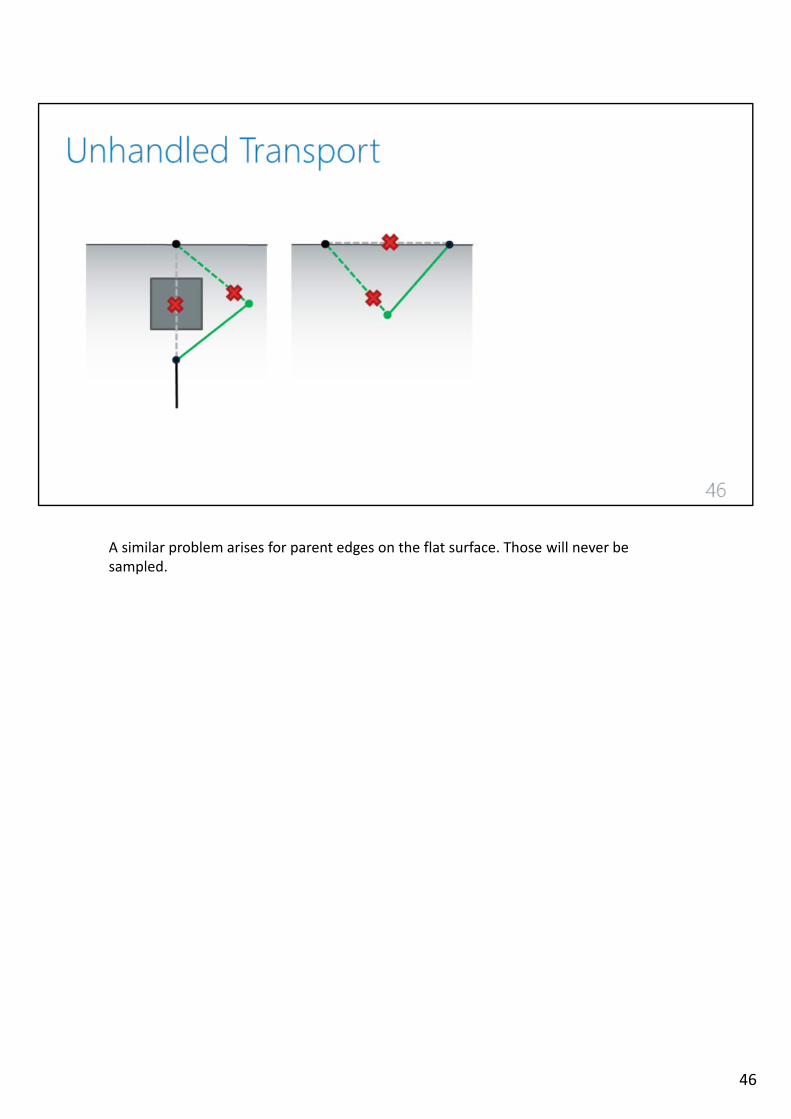
A similar problem arises for parent edges on the flat surface. Those will never besampled.
46
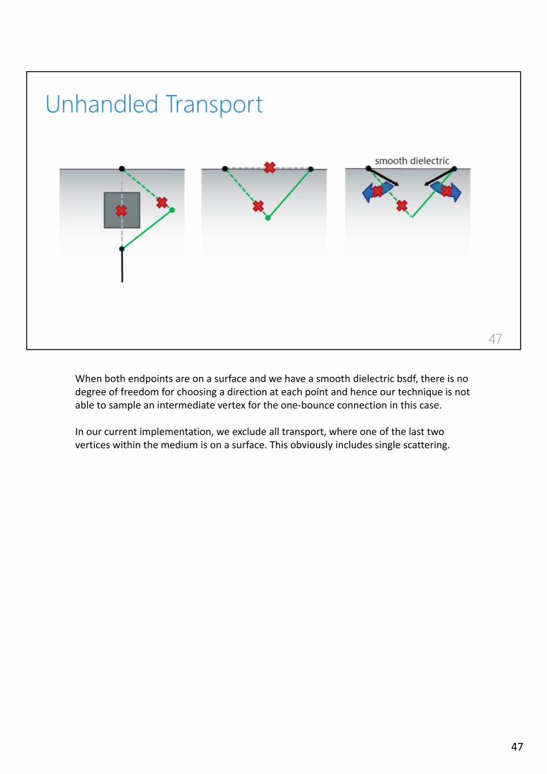
When both endpoints are on a surface and we have a smooth dielectric bsdf, there is nodegree of freedom for choosing a direction at each point and hence our technique is not able to sample an intermediate vertex for the one‐bounce connection in this case.
In our current implementation, we exclude all transport, where one of the last twovertices within the medium is on a surface. This obviously includes single scattering.
47

To account for unhandled transport, we integrate SNEE with a standard unidirectionalpath tracer. The way we do it is by interpreting the last two‐segments of our standardpath tracing sample as a one‐bounce NEE technique and use multi‐sample MIS tocombine it with SNEE.
48
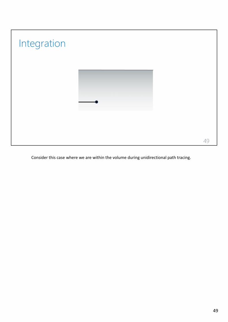
Consider this case where we are within the volume during unidirectional path tracing.
49
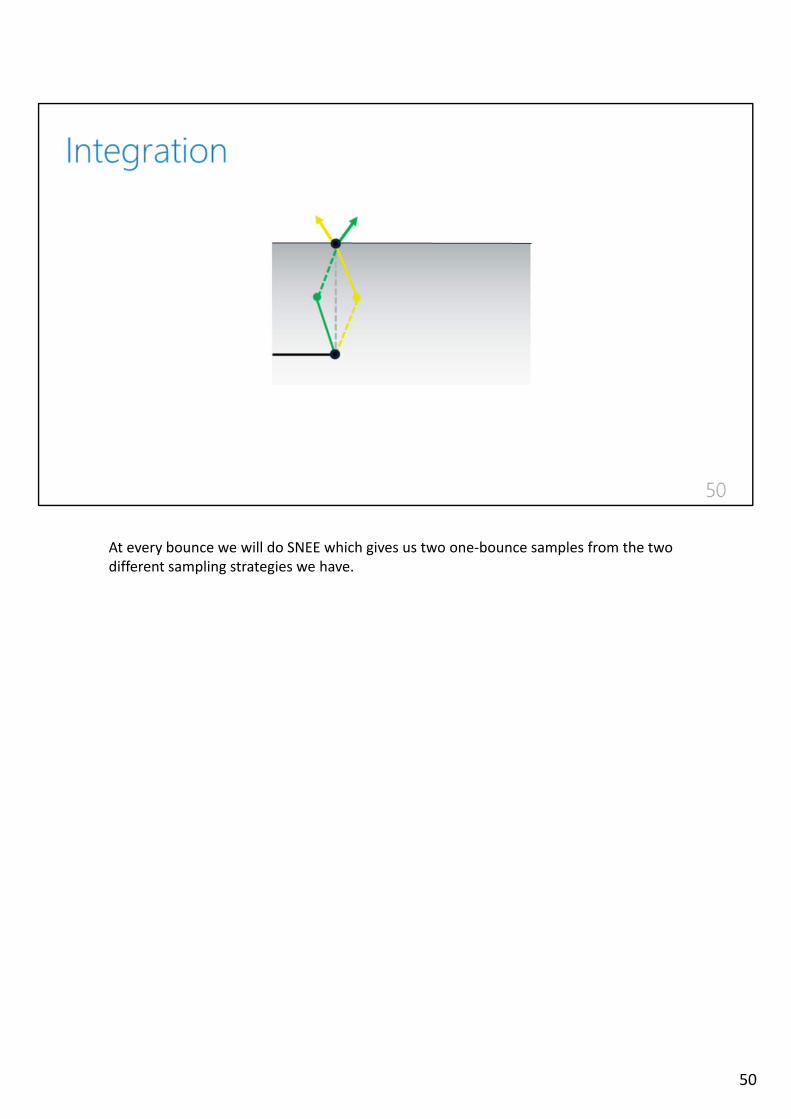
At every bounce we will do SNEE which gives us two one‐bounce samples from the twodifferent sampling strategies we have.
50
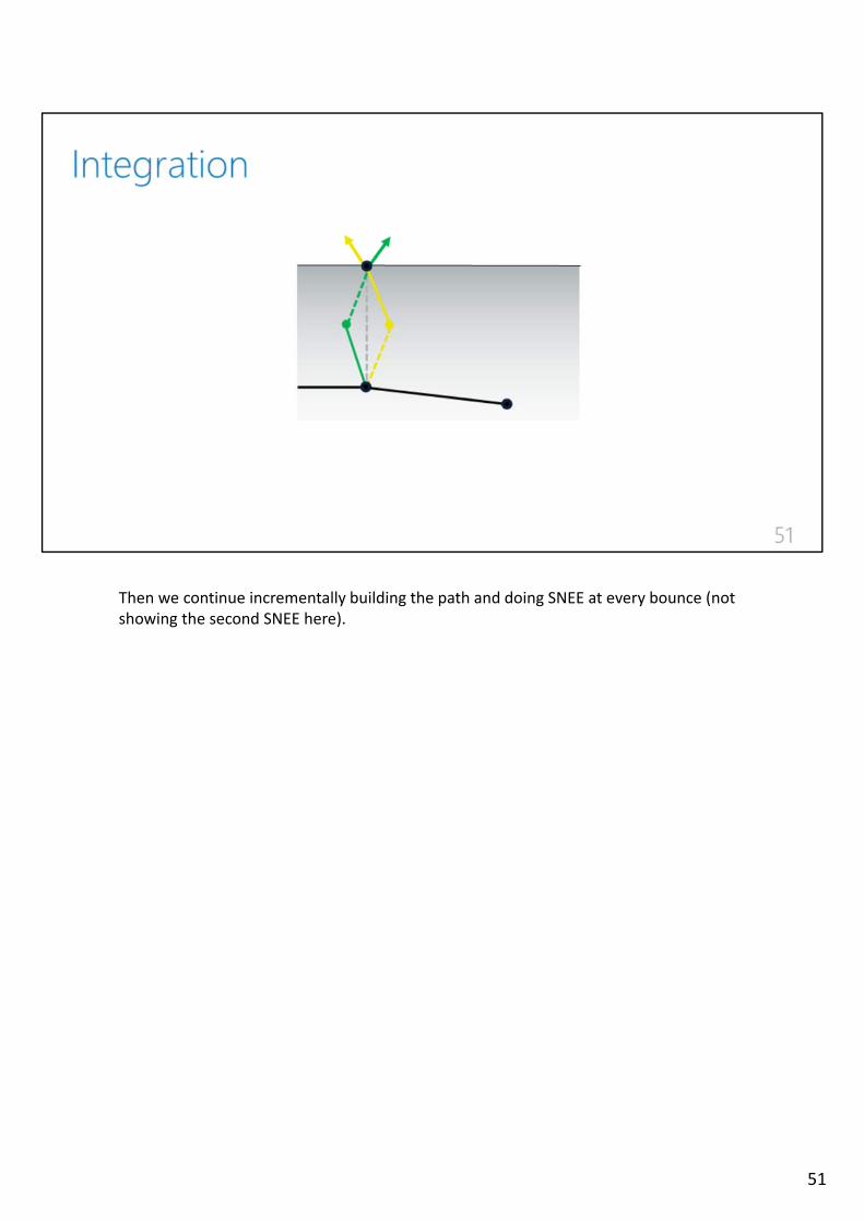
Then we continue incrementally building the path and doing SNEE at every bounce (not showing the second SNEE here).
51
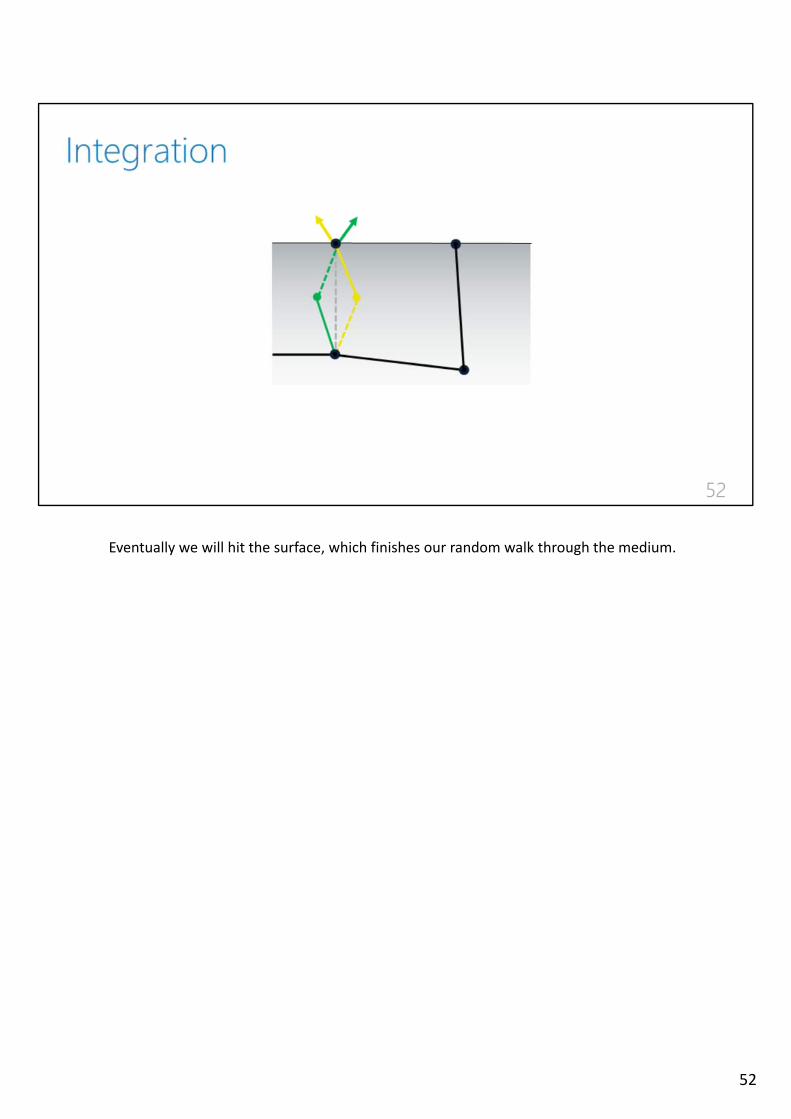
Eventually we will hit the surface, which finishes our random walk through the medium.
52
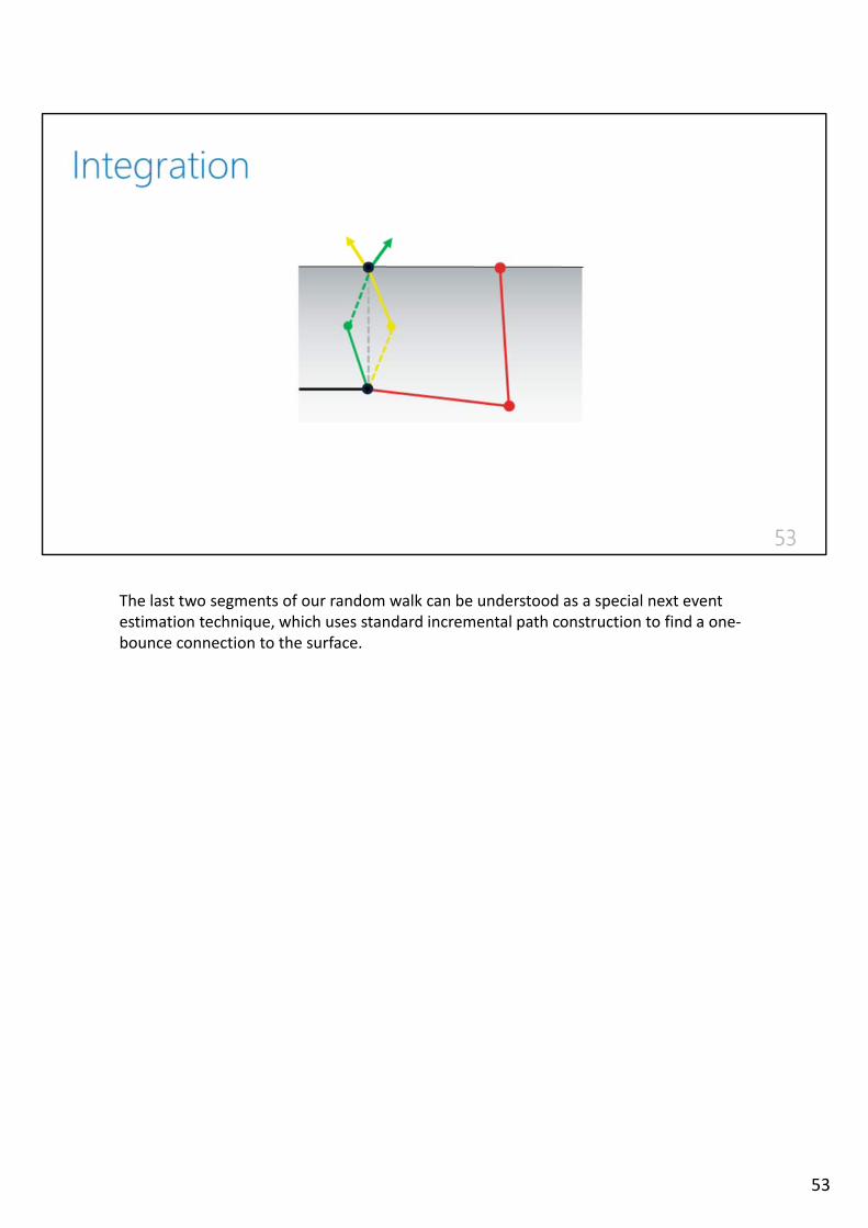
The last two segments of our random walk can be understood as a special next eventestimation technique, which uses standard incremental path construction to find a one‐bounce connection to the surface.
53
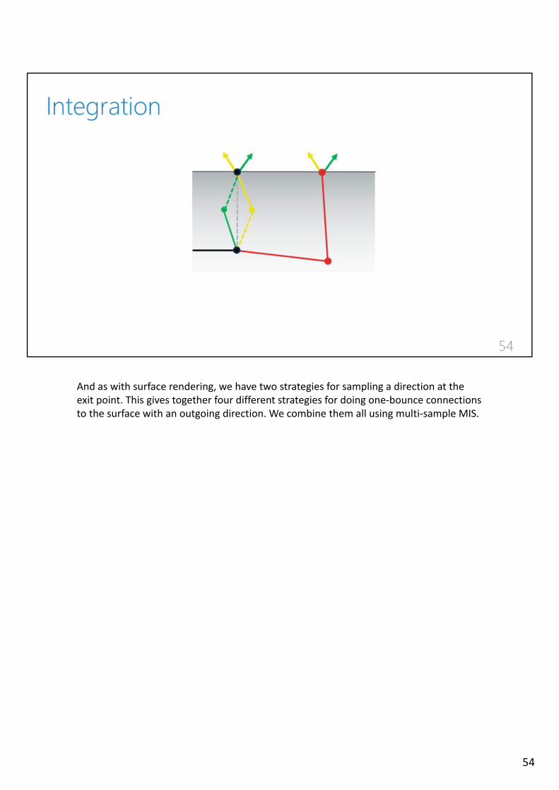
And as with surface rendering, we have two strategies for sampling a direction at theexit point. This gives together four different strategies for doing one‐bounce connectionsto the surface with an outgoing direction. We combine them all using multi‐sample MIS.
54
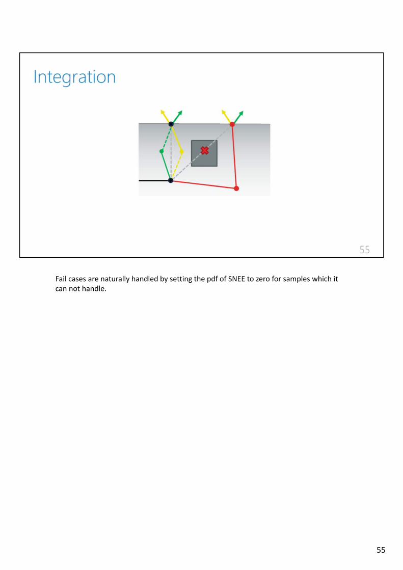
Fail cases are naturally handled by setting the pdf of SNEE to zero for samples which itcan not handle.
55

We now discuss the main result of our paper.
56
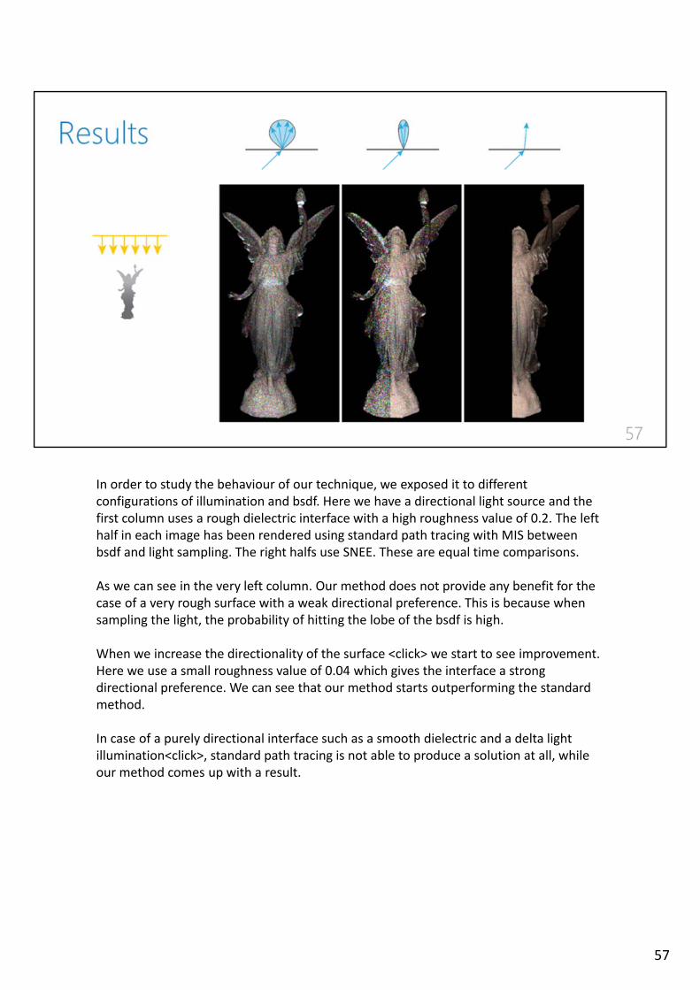
In order to study the behaviour of our technique, we exposed it to differentconfigurations of illumination and bsdf. Here we have a directional light source and thefirst column uses a rough dielectric interface with a high roughness value of 0.2. The lefthalf in each image has been rendered using standard path tracing with MIS betweenbsdf and light sampling. The right halfs use SNEE. These are equal time comparisons.
As we can see in the very left column. Our method does not provide any benefit for thecase of a very rough surface with a weak directional preference. This is because whensampling the light, the probability of hitting the lobe of the bsdf is high.
When we increase the directionality of the surface <click> we start to see improvement. Here we use a small roughness value of 0.04 which gives the interface a strong directional preference. We can see that our method starts outperforming the standardmethod.
In case of a purely directional interface such as a smooth dielectric and a delta light illumination<click>, standard path tracing is not able to produce a solution at all, whileour method comes up with a result.
57
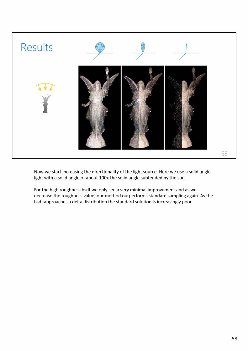
Now we start increasing the directionality of the light source. Here we use a solid angle light with a solid angle of about 100x the solid angle subtended by the sun.
For the high roughness bsdf we only see a very minimal improvement and as wedecrease the roughness value, our method outperforms standard sampling again. As thebsdf approaches a delta distribution the standard solution is increasingly poor.
58
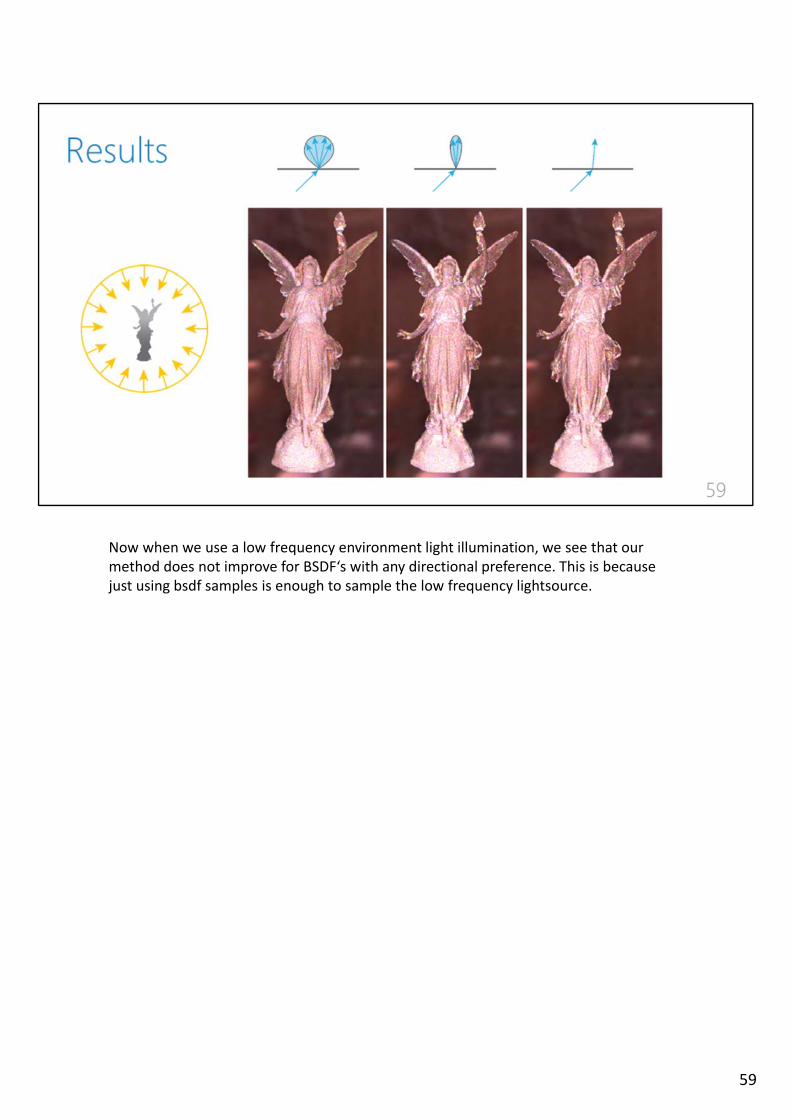
Now when we use a low frequency environment light illumination, we see that ourmethod does not improve for BSDF‘s with any directional preference. This is becausejust using bsdf samples is enough to sample the low frequency lightsource.
59

…which brings us directly to the various things we need to do onwards.
The work we presented today is very much work in progress. All reviewers asked formore extensive evaluation which we very much agree with and the lack of comparisonsis the reason why we submitted to the experimental ideas and implementations track ofegsr. We are planning to do comparisons with MNEE and the work from Holzschuch forthe smooth dielectric. <click>
Currently our method only has a benefit in cases of strong directionality of light or bsdfand degenerates for uniform illumination and surface scattering. It needs to be mademore general in order to be of practical use.
Related to the previous point is the fact that we want to investigate more surface pointsampling techniques and the use of russian roulette to improve the performance of ourmethod in the more general cases. <click>
60

While SNEE is probably not practical in its current form, our work shows that beingcreative in the way path samples are constructed can be benefitial.
Mutation and perturbation strategies in MCMC methods can inspire new avenues in other rendering techniques.
61

Thank you for your attention. We are happy to take questions.
62

63