hella auxiliary headlights: vehicle installation · ideas today for the cars of tomorrow hella...
TRANSCRIPT

Ideas today forthe cars of tomorrow
Hella auxiliary headlights:
Vehicle installation
Lighting Electrics Electronics ThermalManagement
SalesSupport
Our Ideas,Your Success.
TechnicalService

222
Installation of auxiliary headlights
Auxiliary headlights for driving and fog applications are a
meaningful supplement to the existing lighting equipment.
The styled frontal areas and bumpers of modern SUVs
and off-road vehicles make the attachment of auxiliary
headlights a real challenge. In some cases, professional
installation without additional brackets is almost
impossible, which often puts potential customers off. A
few important points must be heeded during the electrical
connection of headlight systems too, to guarantee their
perfect function for years to come.
This brochure provides a host of information, via step-by-step
texts and photos, about installing auxiliary headlights with the aid
of vehicle-specific and universal attachment systems. Valuable
practical tips and advice will help you with the installation of
auxiliary headlights.
KIA Sorento
Page 6–13
Land Rover Defender
Page 14–23
Nissan Qashqai
Page 24–31
VW Tiguan
Page 32–41
The illustrations and step-by-step
details are a demonstration of mounting
possibilities. Please observe national
legislation when mounting and using the
brackets and headlights.

3
On today‘s vehicles, the visible frontal area is usually made of lightweight plastic
composite parts. Their main tasks range from optical design through pedestrian
protection to aerodynamics. The installation of auxiliary headlights is certainly not one of
them. The days when wide, chrome-plated bumpers „decorated“ vehicle front-ends are
long gone. And with them the straightforward possibility of installing auxiliary headlights.
This is a problem that concerns interested off-road drivers in particular. For this reason,
garages often face the challenge of how best to attach the auxiliary headlights to the
vehicle. The answer is: using professional light brackets. These are available in different
shapes, surface finishes and made of various materials. They are available both as
universal and vehicle-specific types. Customers interested in purchasing such light
brackets should always make sure they have been approved by the legislator, however,
since requirements have been significantly tightened, particularly in terms of pedestrian
protection.
Light bracket sets
How can the headlights be attached to the vehicle?
For the attachment examples shown in this brochure we used the „Q-light“ light bracket series
made by the Swedish company QPAX. The brackets are made of aluminium and have an anodised
finish. In addition, this bracket series complies with European guidelines and is supplied in two
different versions:
Universal light bracket
This attachment set is made up of one light bracket, two spacer sleeves and various mounting
parts such as screws, washers etc.. A general installation manual is also supplied as part of the set.
Vehicle-specific light brackets
These bracket sets have been adapted in form and attachment position to suit specific vehicles.
This includes the spacer sleeves and the other mounting parts, plus the installation manual. This is
particularly advantageous when determining the attachment position and position of the drill holes.
All the necessary dimensions and drill hole diameters are available. Various working steps are also
explained. However, the installation instructions do not claim to be complete!

4
Practical tip
Careful preparation is required before commencing the installation of additional
headlights or lights. The following details must be checked first:
Can the headlight be attached without additional installation material (light
bracket etc.)?
! If not, what else do I need?
! What is behind the front apron?
! Are there any solid metal parts the headlights could be mounted to?
! Are there any hoses, pipes, radiators or other components installed that could make
installation more difficult or even impossible?
! What is attachment and installation situation for Xenon headlights like? Is there a
suitable space available for the ballast units?
! What is required for electrical connection (relays etc.) of the headlights?
! Do any special points have to be remembered when connecting up to the vehicle
electronics?
If a garage has had no experience with any particular vehicle, it makes good sense to
have a closer look at the vehicle and remove the front apron if necessary. This allows
possible problems to be anticipated in advance. It also allows the work required to be
estimated much more accurately, so that realistic quotes can be made to customers.
Because if experience has shown us one thing it’s that a day can pass in no time!
General note
With some vehicles, installing the ballasts near the headlight may present a problem
e.g. excessive exposure to water/splashing. With 4th generation ballasts (see photo),
the supply cable from the ballast to the headlight is a metre long and thus covers the
majority of attachment situations. If this should not be sufficient, however, there is
also a three metre supply cable available, this can be ordered under the part number
8KB 990 299-251. This should be long enough to install the ballast units in the
interior or in a splashwater-proof area – if required.

5
In the case of light bracket mounting, it must be assumed that further material in the
form of cable ties, washers etc. is required. Below is a short list of some of the materials
that were used during installation:
Ring groove nut
Due to the shapes of some vehicle profiles it is not possible to set up a screw-type
connection, since the nut cannot be screwed onto the screw thread in the profile. The
screw thread is quite simply out of reach. Ring rivet nuts are a very good alternative
solution in such cases (see photo).
First, a hole of the required size is drilled in the profile. Then the ring groove nut is
inserted and pressed in place. These nuts are available in different sizes and in a set
with the appropriate installation tool. They are easy to use and quickly installed.
Additional installation material
Threaded rods
If a screw connection has to be set up over a longer distance, these threaded rods can
be used. They simply have to be cut to the correct length, are already being supplied as
a set and are easy to purchase.
Rubber seal
Due to the shape of some cross members behind the front aprons, the spacer sleeves
face outwards after tightening, rather than being parallel to the vehicle axis. Mounting
the light bracket would be impossible in this position. The use of thicker rubber seals
from the sanitary market allows the „slant“ of the spacer sleeves to be compensated for.
Crimp-shrink connectors
When electrical connections are to be made by means of a crimp connector, we always
recommend the use of shrink connectors on the outside.
They are absolutely vital in the splashwater area. The nylon sheathing shrinks, producing
a watertight connection and thus guaranteeing perfect contact.

6
A universal attachment set is used for this installation. For this
reason, the set includes different attachment and mounting parts
that have to be adapted to the respective vehicle involved. The
installation manual contains basic working steps, dimensions and
drilling diameters.
Due to the situation with the Sorento, the following
additional materials must be procured:
1. Since „normal“ mounting with stop nuts is not possible, the
8 mm screws are replaced by two 6 mm threaded rods which
are at least 250 mm long.
2. An aluminium tube, 600 mm long, with an interior diameter of
min. 6.5 mm and an outer diameter of max. 8 mm. The matching
small tubes can be see in the photos. These are pushed into
the spacer sleeves to compensate the smaller diameter of the
threaded rods compared to the 8 mm screws in the set. This
prevents the spacer sleeves slipping during mounting of the light
bracket.
3. As already mentioned in the section „Additional installation
material“, it is not possible to attach the threaded rods using stop
nuts on account of the cross member profile. For this reason,
two 6 mm ring groove nuts and two body washers are used.
Attachment of auxiliary spotlights to a Kia Sorento
AfterBefore
1
2
3

7
Attachment is explained step-by-step below:
1 Unscrew and remove the expanding rivets (x 16) on the lock
plate trim.
2 Remove the headlights. To do this, remove the three
attachment screws and pull the headlights to the front and out of
the body. Disconnect the plug-type connection for the low beam,
high beam and position light.
2a
2b
2a 2b
Kia Sorento
3 Particularly when using a universal light bracket, it is important
to establish in advance exactly where this can be mounted to
the body front. Quite often, a potentially suitable space on the
front apron cannot be used because there is no solid metal part
available behind the apron for attachment of the light bracket in
this position. With many vehicles, the cross member (see photo)
provides the best solution. This means the front apron has to be
removed to determined where the drill holes have to be made.

8
Kia Sorento
5a 5b5 Loosen and remove the expanding rivets (x 14) on the front
apron. Remove the attachment nuts in the wings (arrows).
5a 5b
6 Remove the screws (x 2) above the licence plate.
4 Loosen the expanding rivets (x 2) and take the trim off.

9
7 Loosen the expanding rivets on the front of the wheel housing
trims so that these can be pulled away sufficiently to reach the
screws on the underside of the wing. Remove the screws.
7a
7b
7a 7b
Kia Sorento
8 Remove the covers from the nozzles of the headlight cleaning
system. To do this, pull the nozzles upwards by hand and use a
screwdriver to release the cover cap.
9 Take the front apron off and loosen the plug-type connection
for the fog lights.
10 Measure and mark the drill holes on the cross member.
Then „insert“ the front apron loosely on the vehicle again.
Transfer the drilling positions to the front apron. First, pre-drill
the holes using a 5 mm drill and then expand them using a bore
cutter so that spacer sleeves fit through.

10
Kia Sorento
11 Remove the front apron again. Use a 4 mm drill to pre-drill
holes for the ring groove nuts, expand the holes to a suitable size
for the diameter of the nuts and seal them with rust protection.
12 Use both body washers to make sure the contact surface
of the ring groove nuts is flat (see Fig. 12a). Insert the nuts in the
drill holes and mount according to instructions.
12a
13 „Insert“ the front apron on the vehicle again.
14 The spacer sleeves and aluminium tubes must be adapted
in length in such a way that a space of about 10 mm remains
between the light bracket and the front apron after mounting.
Note! During fitting, take the thickness of the plastic washers
into account. Then remove burr from the „intersection“ and
sand it flat (using a file or a belt sander).
14a

11
Kia Sorento
15 Now cut the threaded rods to the right length, too. To do
this, screw the rods about 15 mm into the ring groove nuts. Push
the prepared spacer sleeves, aluminium tubes and light bracket
onto the threaded rods. Use nuts to tighten the light bracket
slightly. Shorten the threaded rods as shown in the photo. We
recommend removing the rods again for this working step.
Remove the front apron again.
16 Due to the space situation in the engine compartment, the
Xenon ballast units are attached to the underbody protection.
To do this proceed as follows:
! Remove the underbody protection
! Mark drill holes, drill them using a 4 mm drill and seal with rust
protection (see Fig. 16a).
! Fasten the underbody protection back into place.
! Attach the ballast units using Parker screws
(see Fig. 16b).
17 Re-fit all the parts that have been removed back on the
vehicle. Fasten light brackets with stop nuts as the final mounting
step.
16b
16a

12
18 Mount the auxiliary headlights onto the brackets according
to the Hella instructions.
20 In this case, Luminator Compact Xenon are installed.
There is a pre-assembled harness included with every
headlight. Determine a suitable spot on each side of the engine
compartment to mount the relays (depending on the engine
type). Mount the relays in a position protected from splashwater
and with the contacts facing downwards. Route the cable
according to the circuit diagram, fix in place using cable ties
and connect up. Take the switching current (terminal 56a, high
beam) for the relay from the central plugs on the headlights using
incision connectors or butt joints. Then wind insulating tape
around the connection points.
Kia Sorento
19 Route the headlight cable through the front apron to the
ballast units and use cable ties to fix it in place at suitable points
on the body.
Driver side: Yellow cable
Passenger side: Yellow cable
21 Test headlight function.

13
22 Adjust the headlights using a beamsetter and tighten the
screws. Tighten the nuts on the light brackets again and use the
black caps to seal the openings.
Kia Sorento

14
A universal attachment set is used for this installation. For this
reason, the set includes different attachment and mounting parts
that have to be adapted to the specific vehicle involved. The
installation manual contains basic working steps, dimensions and
drilling diameters.
In the case of the Land Rover Defender, the light bracket can
be attached directly to the solid bumper, which makes the
mechanical installation much easier.
Since two headlights with a reference number of 37.5 each are
used here, they have to be switched on using a separate switch,
since the vehicle‘s own high beam is to remain active. For this
reason, the electrical connection for this vehicle is described in
more detail. A switch (6EG 001 567-112), installation material
(shrink connectors, ring connectors etc.) and additional cable
material are required for the electrical connection.
Attachment of auxiliary spotlights to a Land Rover Defender 110
AfterBefore

15
Attachment is explained step-by-step below:
1 With this vehicle, the light bracket is not attached in front of
the front apron, but to the top of the bumper instead.
Mark the drill holes for the light bracket on the bumper –
according to the specification in the installation manual. The
holes already present will help with alignment to the centre. Then
pre-drill the holes using a 3 mm drill and widen them using an
8.5 mm drill. Seal the drill holes using rust protection.
2 Fix the attachment height of the light bracket. In this case, the
spacer sleeves are shortened to 40 mm. Then remove burr from
the „intersection“ and sand it flat (using a file or a belt sander).
Land Rover Defender
3 Attach the light bracket to the bumper according to the
instructions (see Fig. 3a). Make sure the individual components
are aligned optimally to one another (see Fig. 3b). 3b
3a

16
Land Rover Defender
5 Find a suitable spot for the ballast units. In this case, the
bumper is ideal due to its dimensions.
6 To mark the drill holes, simply hold the ballast unit on the
bumper from below.
4 Assemble the headlight according to the instructions, attach it
to the light bracket and carry out rough alignment.
Jumbo 320 Xenon are being installed on this vehicle. There is a
pre-assembled harness included with every headlight.
7 Drill holes (4.5 mm) and seal them with rust protection.

17
8 Fix the two ballast units using the screws (M4) included as
part of the kit.
Land Rover Defender
9 Route the headlight cables to the ballast units and connect up.
10 As already explained, there is a pre-assembled harness
included with every headlight. Find a suitable spot to mount the
relay. In the case of the Defender, the existing screw attachment
points on the right and left of the engine compartment can be
used. Mount the relays protected from splashwater and with the
contacts facing downwards.
11 Carry out electrical connection as follows:
The driver seat has to be removed for access to the battery. To
do this, unscrew the screws (x 4) on the seat rails. Loosen and
remove the covers on the battery compartment.

18
Land Rover Defender
13 Route the cables forwards to the relays and use cable ties
to fix them to existing lines on the underbody. The cables have
to be extended due to the distance. This can be done quickly
using shrink connectors, however. Shrink tubes or Bouchier
tubes should be used to better protect the cables from outer
influences. Connect the cables to the relays again.
12 Pull the red cables (load current, terminal 30) off the relays.
Then push the cables through the rubber seal into the propeller
shaft tunnel (see Fig. 12a). Fig. 12b shows the feed through in
the propeller shaft tunnel.
14 Route the voltage supply cables for the ballast units to
the relays. The cables can be pushed up easily when fixed to
welding wire. The radiator grille can also be removed to make
mounting easier. Use cable ties to fix the cable at suitable points.
12a
12b

19
15 Collect the cables and lines in loops together on the ballast
units and fix them in place using cable ties.
Land Rover Defender
16 The voltage supply for the LED position light in the
headlights is taken from the vehicle’s position lights. To do
this, unscrew the headlight trims as well as the indicator and
position light. Please note: European guideline no. 48 specifies
that in the attachment position for the auxiliary headlight shown,
the position light must not be operated. This must always be
heeded.
17 Connect the LED position light using incision connectors or
butt joints.

20
Land Rover Defender
19 The lower steering column trim has to be removed for
installation of the switch. Loosen the cross-slot screws (x 7) and
remove the trim. A suitable hole for the switch is already available
in the steering column trim.
18 With this vehicle, the circuitry has been chosen in such
a way that the auxiliary spotlights can only be activated with
the low beam light switched on. For the separate switch in the
cockpit, the switching current is tapped from the triple plug for
the H4 bulb.
20 To feed the cable through, the dashboard must be pulled off
slightly. To do this, unscrew the attachment screws (x 4) on the
left and right of the dashboard.
20a 20b20a
20b

21
21 Route all the relevant cables for the separate switch
(terminals: 56b, 31 and two x 86) to the interior with the aid of
welding wire. Penetrate the rubber seal to do this. Since there is
no suitable ground point within the dashboard, a ground cable
also has to be laid.
Land Rover Defender
22 Fit 6.3 mm crimp connectors to the cable ends (except
for the white/yellow cable) and then connect up correctly to
the switch. Connect the two white/yellow cables (terminal 86)
together (see Fig. 22a).
23 Mount the steering column trim again and then fix the switch
in place.
24 Attach the ground cables of the relays and switch to suitable
ground points in the engine compartment.
22a
22a

22
Land Rover Defender
26 Re-fit all the parts that have been removed. Route all cables
cleanly and use cable ties to fix them at suitable points.
25 Connect the two red cables (terminal 30) to the battery.
27 Check the headlights for perfect function.
28 Adjust the headlights using a beamsetter and tighten the
screws. Tighten the attachment screws on the light brackets
again and use the black caps to seal the openings.

23
Land Rover Defender

24
Attachment of auxiliary spotlights to aNissan Qashqai
A vehicle-specific attachment set is used for this installation. In
contrast to a universal light bracket, the attachment elements
included as part of the set in this case have been matched to the
vehicle (see photo).
This makes the mounting procedure easier and reduces the
amount of time required.
AfterBefore
1
2
Although this is a vehicle-specific set, various other
installation parts have to be made yourself (see photo).
The following additional material is required for
mounting on the Nissan Qashqai:
1. 2 thick washers (per side)
2. Rubber seals 5 mm thick from the sanitary market.

25
Nissan Qashqai
Attachment is explained step-by-step below:
2 Pull the radiator grille forwards out of the front apron. Note!
The retaining shackles are made of thin plastic
! Danger of breaking off.
3 Remove the licence plate.
1 Loosen and remove the expanding rivets (x 4) on the radiator
grille.
1a
1b
1a 1b

26
4 Loosen the expanding rivets (x 7) from the covers (see
arrows) and remove. Take covers out.
5 Mark the drill holes for the light bracket on the front apron
according to the instructions in the installation manual. Make
sure that the horizontal dimension of 622 mm is kept exactly.
Otherwise, in the case of a slight deviation to the right, the
cover cap on the towing hook will be damaged when the hole is
expanded to 20 mm.
Nissan Qashqai
6 Use a 5 mm drill for pre-drilling and then expand to 20 mm
using a bore cutter.
7 Remove the foam behind the holes to such an extent that the
drilling points can be marked on the metal carrier.

27
Nissan Qashqai
8 Mount spacers onto the light bracket with the aid of the
attachment screws. Now hold the light bracket (parallel to the
floor) against the front apron and push carefully through the
holes until the spacers meet the metal carrier. Mark these points.
This procedure is best carried out by two people together. Then
remove the light bracket from the front apron again.
9 In contrast to the instructions in the manual, the front apron
has to be removed. There are two reasons for this. Two 9 mm
holes have to be drilled in the metal carrier for attachment of the
light bracket. A 9 mm standard drill is not long enough, however,
to bridge the gap between the front apron and the metal carrier.
In addition, the metal carrier is not parallel to the front apron,
which means that the drill would „run off“ to the outer edge every
time drilling was started.
Remove the front apron as follows:
! Unscrew the lower attachment screws (hex screws in the
centre and two cross-slot screws each on the outside) (see
Fig. 9a).
! Loosen the expanding rivets on the front of the wheel housing
trims so that these can be pulled away sufficiently to reach the
screws on the underside of the wing. One expanding rivet per
wheelhouse (see Fig. 9b).
9b
9a

28
! Unscrew the cross-slot screws (see Fig. 9d).
Nissan Qashqai
9d
9c! Pull the decorative strips off the wings by means of the 4 clips.
Note! The clips can break off if too much force is used
(see Fig. 9c).
! Pull the ends of the front apron outwards out of the catches. If
fog lights are installed, disconnect the plug connection.

29
Nissan Qashqai
10 Remove the foam moulded part. To do this push the
attachment clips off forwards.
11 Drill holes in the metal carrier. Pre-drill with a 3 mm drill first
and then expand with a 9 mm drill. Seal the drill holes using rust
protection.
12 Re-attach the foam moulded part.
13 Refit all the removed parts (except for the radiator grille and
covers from section 4).
30
Nissan Qashqai
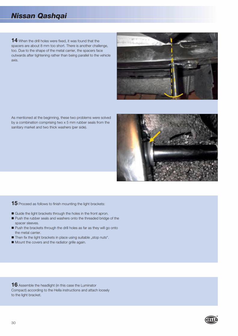
15 Proceed as follows to finish mounting the light brackets:
! Guide the light brackets through the holes in the front apron.
! Push the rubber seals and washers onto the threaded bridge of the
spacer sleeves.
! Push the brackets through the drill holes as far as they will go onto
the metal carrier.
! Then fix the light brackets in place using suitable „stop nuts“.
! Mount the covers and the radiator grille again.
16 Assemble the headlight (in this case the Luminator
Compact) according to the Hella instructions and attach loosely
to the light bracket.
14 When the drill holes were fixed, it was found that the
spacers are about 8 mm too short. There is another challenge,
too. Due to the shape of the metal carrier, the spacers face
outwards after tightening rather than being parallel to the vehicle
axis.
As mentioned at the beginning, these two problems were solved
by a combination comprising two x 5 mm rubber seals from the
sanitary market and two thick washers (per side).

31
Nissan Qashqai
18 A relay is required for operation of the auxiliary headlights.
The working current relay 4RA 003 510-081 can be used for this
purpose. Look for a suitable spot for the relay (depending on the
engine version) and fix it in place. With the test vehicle, we decided
in favour of a point on the upper cross member behind the left
headlight.
Connect headlights and relays in accordance with the circuit
diagram. The switching current for the relay (terminal 56a, high
beam) is taken from the green cable (central plug) of the left
headlight with the aid of an incision connector or butt joint.
17 Route the auxiliary headlight cables according to the circuit
diagram and use cable ties to fix them in place at suitable points.
19 Test the headlights for perfect function.
20 Adjust the headlights using a beamsetter and tighten the
screws. Tighten the attachment screws on the light brackets again
and use the black caps to seal the openings.

32
Attachment of auxiliary spotlights to aVW Tiguan
A vehicle-specific attachment set is used for this installation. In
contrast to a universal light bracket, the mounting instructions
and attachment components have been matched to the vehicle
in this case (see photo). This makes the mounting procedure
easier and reduces the amount of time required.
AfterBefore
1
2
Although this is a vehicle-specific set, additional attachment parts
have to be made yourself.
The following additional material is required for
attachment to the VW Tiguan:
1. 2 x M8 bolts 135 mm long
2. 2 spacer sleeves 20 mm long

33
VW Tiguan
Attachment is explained step-by-step below:
1 Remove the licence plate.
2 Remove the radiator grille. To do this, remove the screws (1x
T 25 and 2x T 30) (see photo).
3 Then pull the radiator grille forwards and out of the fixing lugs.
Note! Pull the grille off carefully, since the locating lugs can easily
break off.
4 Transfer the measurements for the drill holes to the front apron
in accordance with the installation manual. Use a 6 mm drill to
drill the holes and expand these to 25 mm using a bore cutter.

34
VW Tiguan
5 Use a Stanley knife to cut the two pieces of moulded foam that
project over the cross member (see photo). This is the only way
the base plates can be attached properly.
6 Loosen the hexagon socket screws (2 mm) on the base
plates.
Note! In contrast to the specification in the installation manual,
the clamp brackets have to be set to a dimension of 44 mm.
Tighten the hexagon socket screws slightly.

35
VW Tiguan
7 Use the enclosed screws to fasten the black spacers to the
base plates.
8 „Insert“ the upper clamp bracket of the base plates onto the
edge of the cross member according to the instructions.
9 The spacer sleeves have to be aligned centrally to the holes in
the front apron. If this is not the case, loosen the clamp bracket
again and carry out „fine adjustment“.

36
VW Tiguan
10 Then tighten the hexagon socket screws (6 mm) in such a
way that the carrier plates can no longer be moved. Then fasten
the hexagon socket screws of the base plates.
11 There are two aluminium spacer sleeves included in the
set for completing the mounting of the light brackets. These are
too short, however. For this reason, two 20 mm spacer sleeves
with the same inner and outer diameter have to be made as
mentioned above.
12 Equally, two new M8 bolts of a suitable length are required.
A new screw on the top, one from the set on the bottom.
(Left: a new sleeve, right: a sleeve from the set).

37
VW Tiguan
13 Hold the light bracket with screws and spacer sleeves in
front of the drill holes. Screw the screws into the spacers and
tighten equally on both sides.
15 With the aid of welding wire, route the cables of both
auxiliary headlights into the engine compartment. The welding
wire is routed at an angle down from the top between the
headlights and the radiator. Then attach the cables to the
welding wire and pull this upwards.
14 Mount the radiator grille again. Attach the auxiliary headlight,
in this case Luminator Compact Xenon, on the bracket in
accordance with the installation manual and roughly align it. Only
tighten the screws by hand at first.

38
VW Tiguan
16 To prevent some cables having to be extended – the
harness with relay and fuse is included as part of every headlight
– both relays are attached to the air intake channel near the
battery. The relay installation location can vary depending on the
engine version, however (in the case of this example, the engine
was a 2.0 TDI version). Before attaching the relay, connect the
two blue cables to PIN 87 of the respective relay.
17 Use an M8 bolt to attach the four ring lugs of the ground
cable to the ground point next to the battery.
18 Connect the two ring lugs for the load current (terminal 30)
to the free connection in the fuse box. To do this, push the two
catches forwards and remove the cover.

39
VW Tiguan
19 The original ring lugs cannot be attached because of their
size. For this reason, crimp smaller lugs to the ends of the
cables. Then attach the two ring lugs using a stop nut.
20 Push the fuse holders together into one unit.
21 Then drill a 3 mm hole in the cover of the air filter box and fix
the fuses in place using a suitable Parker screw.

40
VW Tiguan
22 In order to connect the high beam (signal current), the two
white/yellow cables must be routed from the relays to the central
plugs of the headlights and be shortened accordingly.
23 Route all cables correctly and use cable ties to fix them at
suitable points.
24 Test the headlights for perfect function.
Tip: Releasing the central plugs from the headlights and pulling
them off makes the mounting procedure easier. Subsequently
use an incision connector or butt joint to connect the white/
yellow cables with the grey/white cables (high beam, PIN 11 to
the central plugs). Then fix the plugs to the headlights again.

41
VW Tiguan
25 Adjust the headlights using a beamsetter and tighten the
screws. Tighten the attachment screws on the light brackets
again and use the black caps to seal the openings. Attach the
licence plate to the light bracket.

42
Notes

Hella, Inc.
201 Kelly Drive,
P.O. Box 2665
Peachtree City, GA 30269
Toll Free: 1-877-224-3552
Fax: 1-800-631-7575
www.hellausa.com
© H
ella
KG
aA H
ueck
& C
o., L
ipps
tadt
9Z
2 99
9 12
8-19
4
SC
H/0
9.09
/1.0
P
rinte
d in
Ger
man
y
Ideas today forthe cars of tomorrow