helical torque anchors design examples torque anchors™ design examples ... design example 1 ... a....
TRANSCRIPT

Page 51
To
rqu
e A
nch
or™
Des
ign
Exa
mp
les
Chapter 3
Helical Torque Anchors™
Design Examples
Heavy Weight New Construction
Light Weight New Construction
Basement Wall Tieback Anchors
Retaining Wall Tieback Anchors
Foundation Restoration
Motor Output Torque
Ultimate Capacity from Field Data
EARTH CONTACT PRODUCTS “Designed and Engineered to Perform”
Earth Contact Products, LLC reserves the right to change design features, specifications and products without notice, consistent with our efforts toward continuous product improvement. Please check with Engineering Department, Earth Contact Products to verify that you are
using the most recent information and specifications.

Page 52
Design Example 1 – Heavy Weight New Construction – Cohesionless Soil
Structural Details: New Building – 2 story house with basement
Estimated weight 3,700 lb/ft
Working load on foundation piles – 30,000 lb
Top of pile to be 12” above the soil surface
Soil data:
6 feet of sandy clay fill (CL), stiff Density = 110 pcf
30 feet of medium grained, well graded sand
(SW), medium dense, SPT “N” = 22
Density = 120 pcf ф = 340
TAB-288- NC 3/4 (8x8)
PILE CAP
TAE-288-84
ULT. CAP = 60,000 lb WORKING LOAD = 30,000 lb
12"
Water table = 14 ft
Recommended target depth = 18 ft.
Torque Anchor™
Design:
1. Select the proper capacity equation and
collect the known information.
Because the soil on the site is cohesionless,
Equation 1b from Chapter 1 is used:
Pu = AH (q Nq) Where:
Pw = 30,000 lb
FS = Factor of Safety = 2.0
Pu = Pw x FS = 30,000 lb x 2.0 = 60,000 lb.
hmid = 18 ft.
(Choose the target depth to be 18 ft. This is
the measurement from the surface to
midway between the helical plates.)
q = γ x hmid
q = (110 lb/ft3
x 6 ft) + (120 lb/ft3
x 8 ft) +
(120 – 62) lb/ft3 x 4 ft) = 1,852 lb/ft
2
Nq = 24 “N” = 22 (Chapter 1 - Table 7)
Use Equation 1b to solve for the helical
plate area that is needed.
AH = Pu / (q Nq)
EXTENSION
TAE-288-84 EXTENSION
12"
TAF-288-84 (8",10",12") LEAD SECTION
SANDY CLAY DEPTH = 6' DENSITY =
110 pcf
DEPTH TO MIDWAY
BETWEEN PLATES
= 18'
WATER TABLE = 14'
MINIMUM PRODUCT LENGTH
L = 21-1/2'
AH = 60,000 lb / 1,852 lb/ft2
x 24 10"
AH = 1.35 ft2
2. Select the ECP Helical Torque Anchor™
suitable to support the load.
Referring to Chapter 1, Table 2 the 2-7/8”
diameter x 0.262 wall thickness tubular pile
shaft is selected as most economical for this
application. Our project requires 60,000
pounds of compressive strength. The selected
pile shaft has a Compressive Load Limit of
100,000 pounds and a Useable Torsional
HOMOGENOUS SAND
DEPTH = 30' DENSITY = 120 pcf
DEG.
LENGTH FROM MID- PLATE DEPTH TO
TIP OF PILE S = 3 x (8" + 10") / 2
S = 27" 8"
Strength of 9,500 ft-lbs.
Referring to Chapter 1, Table 10 the
combination of helical plates is selected from the
ft
2
Figure 7. Design Example 1 & 2
of bearing area is needed to support an
row opposite the 2-7/8” shaft size. At least 1.35 ultimate capacity of 60,000 pounds. The data

Page 53
To
rqu
e A
nch
or™
Des
ign
Exa
mp
les
from the 2-7/8” diameter shaft on Table 10 in
Chapter 1 is reproduce here:
6” Dia. = 0.151 ft2
8” Dia. = 0.304 ft2
10” Dia. = 0.500 ft2
12” Dia. = 0.740 ft2
14” Dia. = 1.024 ft2
Select the combination of 8”, 10”, and 12”
diameter plates on the 2-7/8” diameter tubular
shaft.
AH = 0.304 + 0.500 + 0.740 = 1.544 ft2
AH = 1.54 ft2
> 1.35 ft2
This plate combination provides a total area of
1.54 ft2, which exceeds the required plate area of
1.35 ft2, arrived at from Equation 2b.
Designation for the selected Torque Anchor™
configuration is found in the product list on Page
7. The product selected is:
TAF-288-84 08-10-12
3. Installation Torque: Equation 2 in Chapter 1
calculates the estimated installation torque.
Equation 2: T = Pu / k, Where,
Pu = 60,000 lb. (30,000 Working Load x 2.0)
K = 8.5 (Chapter 1 - Table 12)
T = 60,000 lb / 8.5 ft-1
T = 7,100 ft-lb
4. Torque Anchor™
Capacity Verification: A
review of Table 2 in Chapter 1 indicates that the
2-7/8” diameter Torque Anchor™
has a Useable
Torsional Strength of 9,500 ft-lb. The torque
requirement of 7,500 ft-lb is 21% below the
torsional limit of the shaft. The selection should
work for this application based upon the soil
report stating that the soil is sandy clay fill and
homogenous sand with no mention of rocks, debris or other obstructions. A review of Table
11 in Chapter 1 shows that three 3/8” thick
helical plates have a mechanical ultimate
capacity of 120,000 pounds (40,000 lb x 3),
which is double our requirement for this
installation, so the mechanical capacity of the
pile assembly exceeds the project requirements.
5. Installed Product Length. The installed
length required to accomplish this design is a
summation of all the lengths previously provided
and determined.
A. The pile cap is placed 1 ft. above grade level
B. hmid = 18 ft.
C. Length from mid-plate to pile tip (Recall that the helical plates are spaced at three
times the diameter of the nearest lower plate.)
htip = [(3 x 8” dia)+(3 x 10” dia)]/2 = 27”
htip = 2-1/2 ft (Round up to 30”.)
L = 1 ft + 18 ft + 2-1/2 ft
L = 21-1/2 feet
6. Torque Anchor™
Specifications:
The specified Torque Anchor™
assembly will
consist of the following:
TAF-288-84 08-10-12 This is a 2-7/8”
diameter tubular product, having a standard
length of 7 feet long, with an 8”, a 10”, and
a 12” diameter plates that are 3/8” thick,
TAE-288-84 Extension, which is 7 feet long
and includes coupling hardware. The
coupling overlaps the previous section by 6
inches, which provides an effective length of
the extension section at 6-1/2 feet. – Two
extension sections are required
TAE-288-60 Extension, which is 5 feet long
with coupling hardware. The coupling
overlaps the previous section by 6 inches,
which provides an effective extension length
of 4-1/2 feet. – (One extension may be
required.)
TAB-288 NC Pile Cap that fits over the 2-
7/8” diameter tubular shaft and has a 3/4” x
8” x 8” bearing plate.
The total length of the assembled products from the list is actually 24-1/2 feet long. The Torque
Anchors™
shall be installed to minimum depth of
21-1/2 feet at the locations designated on the
plan and must develop a sufficient compressive
strength as determined by the minimum average
installation torque of 7,100 ft-lb at this specified
target depth or lower.
End Design Example 1

Page 54
1 2 3 4 5 6
E
sti
ma
ted
Ult
ima
te C
ap
acit
y
Design Example 1A – Heavy Weight New Construction – “Quick and Rough” Method
Design Details: Compressive Service Load = 30,000 lbs at each
pile. (See Figure 7 above.)
The soil information about the site indicated 6
feet of stiff sandy clay fill (CL) followed by 30
feet medium dense sand (SP)
ECP Torque Anchor™
Design: The soil data
provides only a rough description of the soil on
the site with no SPT, “N”, values or any
indication of water table. The quick estimating
method for designing the compression piles to
support the structure is used. The thorough
analysis for this project using the bearing
capacity equations was demonstrated in Design
Example 1 above. Comparison between the
results of the two methods will be discussed.
1. Determine the Soil Class. Referring to the
Soil Classification Table (Chapter 1 - Table 9) a
Soil Class between 4 and 5 is selected based
upon the description of the soil.
2. Ultimate Helical Pile Capacity. The
engineer provided the Service Load (or working
load) on this project based upon his knowledge
of the calculated structural loading. Because the
pile must have the capability to support more
than just the service capacity, a Factor of Safety
must be added to the Service Load to obtain the
Ultimate Capacity of the pile design. In this
case, a factor of safety of 2.0 is used to arrive at
60,000 pounds per pile ultimate capacity.
3. Select the proper compression pile from the
estimated capacity graphs. Referring to Graph 4 from Chapter 1 (reproduced below), notice that
the capacity line for a Torque Anchor™
with 10”,
12” and 14” diameter helical plates attached
crosses between Soil Class 4 & 5 at 60,000
pounds. The 10”, 12” and 14” diameter plate
configuration is selected for the design.
4. Check the Shaft Strength and Torsional
Strength to see which shaft is suitable. Refer
to Table 2 in Chapter 1 and select the 2-7/8 inch
diameter tubular shaft that has sufficient capacity
to support the load, and has sufficient torsional
shaft strength for installation. The required
ultimate capacity for each pile is 60,000 lbs. The
2-7/8 inch tubular product, with 0.262 inch wall
thickness, has an Axial Compressive Load Limit
rating of 100,000 pounds and a Practical Load Limit based on Torsional Strength of 80,000 pounds assuming a Useable Torsional Strength
of 9,500 ft-lbs. The 2-7/8 inch diameter, 0.262
inch wall helical pile provides suitable torsional
capacity and a sufficient practical load limit to
exceed the ultimate load requirement of 60,000
pounds. The choice is verified.
120000
TORQUE ANCHOR HOLDING CAPACITY Multiple Helical Plate Sizes
12-14" 8-10-12" 10-12-14" 12-14-14"
100000
80000
60000
40000
20000
0
Graph 4. 7 6 5 4 3
Soil Classification
Page 55
Ult
ima
te
Ca
pa
cit
y x
1
,00
0 l
b.
To
rqu
e A
nch
or™
Des
ign
Exa
mp
les
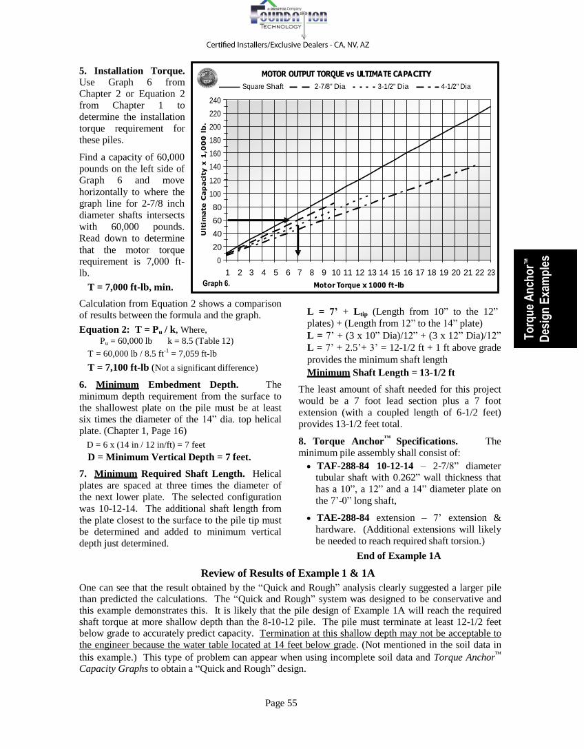
5. Installation Torque.
Use Graph 6 from
Chapter 2 or Equation 2
from Chapter 1 to
determine the installation
torque requirement for
these piles.
Find a capacity of 60,000
pounds on the left side of
Graph 6 and move
horizontally to where the
graph line for 2-7/8 inch
diameter shafts intersects
with 60,000 pounds.
Read down to determine
that the motor torque
requirement is 7,000 ft-
lb.
240
220
200
180
160
140
120
100
80
60
40
20
0
MOTOR OUTPUT TORQUE vs ULTIMA TE CA PA CITY
Square Shaft 2-7/8" Dia 3-1/2" Dia 4-1/2" Dia
1 2 3 4 5 6 7 8 9 10 11 12 13 14 15 16 17 18 19 20 21 22 23
T = 7,000 ft-lb, min. Graph 6. Mot or Torque x 1000 ft -lb
Calculation from Equation 2 shows a comparison
of results between the formula and the graph.
Equation 2: T = Pu / k, Where,
Pu = 60,000 lb k = 8.5 (Table 12)
T = 60,000 lb / 8.5 ft-1
= 7,059 ft-lb
T = 7,100 ft-lb (Not a significant difference)
6. Minimum Embedment Depth. The
minimum depth requirement from the surface to
the shallowest plate on the pile must be at least
six times the diameter of the 14” dia. top helical
plate. (Chapter 1, Page 16)
D = 6 x (14 in / 12 in/ft) = 7 feet
D = Minimum Vertical Depth = 7 feet.
7. Minimum Required Shaft Length. Helical
plates are spaced at three times the diameter of
the next lower plate. The selected configuration
was 10-12-14. The additional shaft length from
the plate closest to the surface to the pile tip must
be determined and added to minimum vertical
depth just determined.
L = 7’ + Ltip (Length from 10” to the 12”
plates) + (Length from 12” to the 14” plate)
L = 7’ + (3 x 10” Dia)/12” + (3 x 12” Dia)/12”
L = 7’ + 2.5’+ 3’ = 12-1/2 ft + 1 ft above grade
provides the minimum shaft length
Minimum Shaft Length = 13-1/2 ft
The least amount of shaft needed for this project
would be a 7 foot lead section plus a 7 foot
extension (with a coupled length of 6-1/2 feet)
provides 13-1/2 feet total.
8. Torque Anchor™
Specifications. The
minimum pile assembly shall consist of:
TAF-288-84 10-12-14 – 2-7/8” diameter tubular shaft with 0.262” wall thickness that
has a 10”, a 12” and a 14” diameter plate on
the 7’-0” long shaft,
TAE-288-84 extension – 7’ extension &
hardware. (Additional extensions will likely
be needed to reach required shaft torsion.)
End of Example 1A
Review of Results of Example 1 & 1A
One can see that the result obtained by the “Quick and Rough” analysis clearly suggested a larger pile than predicted the calculations. The “Quick and Rough” system was designed to be conservative and this example demonstrates this. It is likely that the pile design of Example 1A will reach the required shaft torque at more shallow depth than the 8-10-12 pile. The pile must terminate at least 12-1/2 feet below grade to accurately predict capacity. Termination at this shallow depth may not be acceptable to the engineer because the water table located at 14 feet below grade. (Not mentioned in the soil data in
this example.) This type of problem can appear when using incomplete soil data and Torque Anchor™
Capacity Graphs to obtain a “Quick and Rough” design.

Page 56
Table 15 Conservative Critical Buckling Load Estimates
Shaft Size
Uniform Soil Condition
Organics N < 1
Very Soft Clay N = 1 - 2
Soft Clay N = 2 - 4
Loose Sand N = 2 - 4
1-1/2” Sq 26,000 lb 29,000 lb 33,000 lb 37,000 lb
1-3/4” Sq. 39,000 lb 43,000 lb 48,000 lb 55,000 lb
2-1/4” Sq. 74,000 lb 81,000 lb 90,000 lb 104,000 lb
2-7/8” Dia x 0.203” 36,000 lb 44,000 lb 62,000 lb 51,000 lb
2-7/8” Dia x 0.262” 39,000 lb 48,000 lb 69,000 lb 56,000 lb
3-1/2” Dia x 0.300” 63,000 lb 78,000 lb 110,000 lb 90,000 lb
4-1/2” Dia x 0.337” 113,000 lb 139,000 lb 160,000 lb 160,000 lb
Strength. Table 2 in Chapter 1 lists the Axial
Compression Load Limits for
helical pile shafts when the shafts are installed into soil that provides sufficient
lateral support along the pile shaft
Design Example 1B – Heavy Weight New Construction – Weak Soil
In this variation, the same construction load and
soil conditions prevail as stated in Design
Example 1 with the exception that five feet of
very weak soil now exists directly below the
surface.
Additional Design Details:
The soil data revealed a least five feet of very
loose sand fill and very soft clay organic soil near
the surface.
Standard Penetration Test values for this weak
layer were, “N” = 1 to 3 blows per foot - Soil
Class = 8
Below 5 feet the soil profile is the same as shown
in Design Example 1.
ECP Torque Anchor™
Design: The soil data
here suggests that below the initial five feet of
very weak soil, the soil profile is similar to the
soil in Design Example 1. Referring to Example
1, it can be recalled that the pile configuration
required supporting the 60,000 pound ultimate
load on pile using an 8-10-12 inch diameter plate
configuration. The 2-7/8 inch diameter tubular
shaft, with 0.262 inch wall thickness, had a
sufficient Axial Compressive Load Limit to
support the design load and sufficient Useable
Torsional Strength to install the pile under the
soil conditions represented in Design Example 1.
Knowing that there exists a layer of extremely
weak (Class 8) soil near the surface on this site is
important information because helical piles have
slender shafts and require
sufficient lateral soil support
against the shaft to prevent
shaft buckling under full load.
1. Determine the Buckling
. Testing has suggested
that shaft buckling is not an
issue when the soil has a
SPT value, “N” > 5 blows
per foot for solid square shafts and “N” > 4
blows per foot for tubular shafts.
In this design example there exists a five foot
layer of very weak Class 8 soil consisting of
loose sand and soft organic clay located just
under the surface. These very weak soils overlay
inorganic clay that is able to support the required
load where the soil will provide sufficient lateral
shaft support. However, an Axial Compressive
Load Limit of 100,000 pounds shown in Table 2
for a 2-7/8 inch diameter with 0.262 inch wall
tubular shaft is not valid when this shaft passes
through the Class 8 soil with SPT values
reported to be between 1 and 3 blows per foot.
Instead of using Table 2 from Chapter 1 for the
compressive load limit on the shaft, one must
understand that the upper layer of soil is not able
to provide sufficient lateral support to the shaft
to prevent bucking. Table 15 in Chapter 1
Conservative Critical Buckling Load Estimates
(reproduced below) demonstrates this quite clearly for various soil strengths and types. Referring to Table 15, it can be seen that the estimated buckling strength for the 2-7/8 inch diameter, 0.262 inch wall helical Torque
Anchor™
shaft when it passes through soil
consisting of very loose sand fill and soft organic clay having SPT values that range from “N” = 1 to 3 blows per foot is only 48,000 pounds.
This soil is not capable of lateral shaft support
for 60,000 pound ultimate compressive load
without concern for the shaft buckling within the
weak upper level soils.
2. Select a Pile Shaft with Suitable Buckling Strength. The axial ultimate compressive capacity requirement for this project is 60,000

Page 57
To
rqu
e A
nch
or™
Des
ign
Exa
mp
les
pounds on pile shaft. The selected shaft from
Design Example 1 must be changed to a stiffer
shaft to be able to successfully pass through the
very week upper soil strata without buckling. A
larger diameter tubular shaft is able to offer more
shaft stiffness called Moment of Inertia or
resistance to buckling. Referring once again to
Table 15 (above); notice the row labeled “3-1/2
inch dia. x 0.300” shows a conservative
estimated buckling load capacity of 78,000
pounds for the larger diameter shaft. Because
there exists very weak soil near the surface in
this example, the pile shaft diameter must be
increased to provide resistance to shaft buckling
when the fully loaded pile passes through these
weak soils.
3. Torque Anchor™
Specifications. The
Torque Anchor™
plate configuration remains as originally determined in Design Example 1 to support the structural load, but the shaft diameter must be increased to the 3-1/2 inch diameter,
0.300 inch wall tubular shaft for increased
buckling strength:
TAF-350-84 08-10-12 Lead Section
TAE-350-84 Extension Section (2 required)
TAE-350-60 Extension Section
TAB-350 NC Pile Cap that fits over the 3-
1/2” tubular shaft and has a 3/4” x 8” x 8”
bearing plate.
4. Installation Torque. The larger diameter
tubular shaft now required passes through the
soil less efficiently. This soil friction effect was
fully discussed at the beginning of Chapter 2. As
a result, when the design requires a change in
shaft size, the installation torque requirement
must be recalculated and will be higher for
larger diameter shafts.
A check of Table 12 in Chapter 1 shows that the
3-1/2 inch diameter shaft has a recommended
efficiency factor, “k” = 7-1/2 as compared to “k” = 8-1/2 that was used to estimate installation
shaft torsion requirement for the 2-7/8 inch
diameter tubular shaft.
Use Equation 4 introduced in Chapter 1 and
repeated in Chapter 2 to calculate the new
installation torque requirement for the larger
diameter pile shaft.
Equation 5: T = Pu / k, Where,
Pu = 60,000 lb k = 7.5 (Table 12 – Chapter 1 & 2)
T = 60,000 lb / 7.5 ft-1
= 8,000 ft-lb
T = 8,000 ft-lb, minimum Earth Contact Products recommend that a Registered Professional Engineer conduct the evaluation and design of Helical Torque
Anchors™
where shaft buckling may occur due to the shaft being installed through weak soil or in cases where the shaft is fully exposed without lateral shaft support.
End of Example 1B
Review of Results of Example 1 & 1B
It is very important to remember that buckling is an issue when a pile shaft passes through weak soils
anywhere along the length of the shaft. The key numbers to remember here when looking at soil data
are the Standard Penetration Test, “N”, values throughout the depth of the borings. Watch for soil
strata that are weaker than “N” < 4 blows per foot for solid square shaft installations and “N” < 5 blows
per foot for tubular shafts. When such weak soils may be encountered, a check of the buckling strength
of the selected shaft diameter is necessary.
Whenever the shaft must extend above ground in the air or in water without any later support at all, On
the last page of Chapter 1, Graph 8 is provided to give ultimate load estimates for various shaft
configurations relative to the length of exposed and unsupported column height.
“Designed and Engineered To
Perform”
Technical Design Assistance Earth Contact Products, LLC. has a knowledgeable staff that stands ready to help you with understanding how to prepare preliminary designs, installation procedures, load testing, and documentation of each placement when using ECP Torque Anchors
™. If you have questions or require engineering assistance in evaluating,
designing, and/or specifying Earth Contact Products, please call us at 913 393- 0007, Fax at 913 393-0008.

Page 58
10"
Design Example 2 – Light Weight New Construction – Cohesive Soil
Structural Details: New building – single story brick veneer house on
monolithic concrete slab on grade
The estimated weight is 1,269 lb/lineal ft on the
18” tall steel reinforced perimeter beam
The client wants Torque Anchors™
on the
perimeter of the structure because of lot fill.
Top of shaft to be one foot below soil surface
Soil data:
4 feet of poorly compacted fill – “N” = 5
6 feet of silty clay (CH) – “N” = 5 to 7
15 feet of very stiff clay (CL) –
“N”= 25 to 30 blows per foot.
Torque Anchor™
Design:
1. Select suitable pile spacing and working load
from the description of the foundation beam. Use Equation 3 from Chapter 1 to determine the
working load on the helical pile. From Graph 2 - Chapter 6, for an 18” beam choose “X” = 7 ft.
TAB-150- NC 1/2 (6x6)
ULT. CAP = 17,766 lb WORKING LOAD = 8,883 lb
POORLY
COMPACTED FILL
Equation 3: Pu
Where,
= (“X”) x (w) x (FS):
™
PILE CAP
DEPTH = 4'
Pu = Ultimate Capacity of Torque Anchor w = Foundation Load (lb/ft)
= 1,269 lb/lineal foot
FS = 2.0
“X” = Product Spacing = 7 ft
PU = 1,269 lb/ft x 7 ft x 2.0
PU = 17,766 lb (Use 18,000 lb.)
(lb)
TAE-150-84 EXTENSION
STIFF SILTY CLAY
DEPTH = 15'
DENSITY = 120 pcf
SOFT SILTY CLAY DEPTH = 6'
MINIMUM PRODUCT LENGTH L = 18'
PU = 18,000 lb SPT - "N" = 12 - 16
2. Select the proper ultimate capacity equation
and collect the known information. Because the soil on the site is cohesive (clay), Equation 1a
from Chapter 1 is used:
Equation 1a: AH = Pu / (9c) Where:
Pu = 18,000 lb
c = 3,400 lb/ft2
(Table 5 – Assume “N” = 27 bpf)
8"
TAF-150-60 08-08
LEAD SECTION
LENGTH TO EMBED HELICAL PLATES S = 3 x (8") = 24"
AH = Pu / (9 x 3,400)
AH = 18,000 lb / 30,600 lb/ft2
AH = 0.59 ft2
3. Select the ECP Helical Torque Anchor™
suitable to support the load. The requirement states an ultimate compressive capacity of
18,000 lb. Referring to Table 2 in Chapter 1 the
1-1/2” solid square pile shaft is an economical
choice because it has an Axial Compressive Load
Limit rating of 70,000 pounds and a Useable Torsional Strength of 7,000 ft-lbs.
Figure 8. Design Example 2
Referring to Table 10 – Chapter 1, select a
combination of plates from the row opposite the
1-1/2” square shaft size. At least 0.59 ft2
of
bearing area is required:
6” Dia. = 0.181 ft2
8” Dia. = 0.333 ft2
10” Dia. = 0.530 ft2
12” Dia. = 0.770 ft2
The combination of 8 inch diameter plates on the
1-1/2” solid square shaft is selected.
AH = 0.333 + 0.333 = 0.67 ft2 > 0.59 ft
2 - O.K.

Page 59
To
rqu
e A
nch
or™
Des
ign
Exa
mp
les
This plate combination provides a total area of
0.67 ft2, which exceeds the required 0.59 ft
2. As
an alternate, a single 12” diameter plate could be
selected with a projected area of 0.77 ft2.
The product designation for the standard length
Torque Anchor™
product is selected from the
standard product listing on Page 5:
TAF-150-60 08-08
4. Installation Torque: Equation 2 in Chapter 1
gives an estimation of the required installation
very stiff clay stratum. The installed length
required to accomplish this design depth is:
The depth from the surface to bearing = 18 ft.
The pile cap is specified at one foot below
grade level = 18 ft – 1ft = 17 feet
The distance to midway between the twin 8 inch
plates is 1 ft. (8” x 3D8” = 24 in/2 = 12 inches)
The minimum shaft length requirement is:
L = 17 ft + 1 ft = 18 ft
™
shaft torsion. It is determined as follows: 7. Torque Anchor Specifications: The
Equation 2: T = Pu / k
Where,
Pu = 18,000 lb
k = 10 (Table 12)
T = 18,000 lb / 10 ft-1
T = 1,800 ft-lb
5. Torque Anchor™
Capacity Verification: A
review of Table 2 in Chapter 1 indicates that the
1-1/2” solid square bar Torque Anchor™
has a
Useable Torsional Strength of 7,000 ft-lb, which
is nearly four times the required installation
torque. There was no mention of rocks, debris or
other obstructions in the project information.
This is excellent product for this project. Table
9 in Chapter 1 shows the Ultimate Mechanical
Helical Plate Capacity of 80,000 pounds (40,000
lb x 2) for the two 3/8” thick helical plates. The
mechanical capacity of the selected pile
configuration is more than adequate.
6. Installed Product Length. The stiff silty clay
has been targeted as the soil where the helical
plates will be founded. A depth of 18 feet is
selected to set the plates below the weaker soils.
This places the plates within the middle of the
Torque Anchor™
assembly is specified from the
standard products listed near the beginning of
Chapter 1:
TAF-150-60 08-08, which is a 1-1/2” solid
square bar product on a standard 5 foot long
shaft, with twin 8 inch diameter 3/8” thick
plates
TAE-150-84 Extension, which is 7 feet long,
but the coupling overlaps 3 inches providing
an effective length of 6’-9” The extension
includes coupling hardware. Two extensions
are required.
TAB-150 NC Pile Cap that fits over the 1-
1/2” square bar and has a 1/2” x 6” x 6”
bearing plate.
The total length of the assembled products from
above is exactly 18-1/2 feet long. Placements
shall be 7 feet on center along the perimeter
grade beam and must develop an average
installation torque of 1,800 ft-lb or more at the
target depth of 18 feet. It is recommended that
additional extension be on hand in case the shaft
torque requirement is not achieved at 18 feet.
End Design Example 2
“Designed and Engineered To
Perform”
Technical Design Assistance Earth Contact Products, LLC. has a knowledgeable staff that stands ready to help you with understanding how to prepare preliminary designs, installation procedures, load testing, and documentation of each placement
when using ECP Torque Anchors™
. If you have questions or require engineering assistance in evaluating, designing, and/or specifying Earth Contact Products, please call us at 913 393-0007, Fax at 913 393-0008.

Page 60
1 2 3 4 5 6
Esti
ma
ted
Ult
ima
te C
ap
acit
y
Design Example 2A – Light Weight New Construction – “Quick and Rough” Method
Design Details from Design Example 2: The ultimate capacity on each pile spaced at 7
feet on center is 18,000 pounds
Top of shaft to be one foot below soil surface
Soil data:
4 feet of poorly compacted fill followed by 6
feet of silty clay (CH) over 15 feet of very stiff
clay (CL)
ECP Torque Anchor™
Design: Because this
is a compressive load application and there is
some poorly compacted
and a sufficient practical load limit to exceed
the ultimate job load requirement of 18,000
pounds. Table 9 in Chapter 1 shows the
Ultimate Mechanical Helical Plate Capacity of
80,000 pounds (40,000 lb x 2) for the two 3/8”
thick helical plates. The selected and verified
pile configuration is TAF-150-60 08-08 and is smaller than recommended from the earlier
calculations in Design Example 2.
fill exists the selection of
Soil Class must be
conservative.
1. Determine the Soil
Class. Referring to the Soil Classification Table
(Table 9 – Chapter 1) and
noticing that the clay on
the site is very stiff, Soil
Class 4 is selected. The
poorly compacted fill
should not be a problem
at this light loading as
long as the helical plates
70000
60000
50000
40000
30000
20000
10000
0
TORQUE ANCHOR HOLDING CAPACITY Multiple Helical Plate Sizes
8-8" 8-10" 10-10" 10-12"
are founded into the
underlying very stiff clay.
Graph 3. 7 6 5 4 3
Soil Classification
2. Select the proper compression pile
configuration from the estimated capacity
graphs. Referring to Graph 3 from Chapter 1
(reproduced right), notice that the capacity line
for an anchor with two 8” diameter helical
plates attached crosses the midpoint of Soil
Class 4 at 22,000 lb. The 8” – 8” diameter
plate configuration is selected for the design.
3. Check the Shaft Strength and Torsional
Strength to see which shaft is suitable. Refer to Table 2 in Chapter 1 to find a shaft with a
suitable Axial Compression Load Limit and sufficient Useable Torsional Strength. The 1-
1/2 inch solid square shaft has an Axial
Compression Load Limit rating of 70,000
pounds based upon an installation torsional
limit of 7,000 ft-lbs. The selected pile shaft
provides suitable Useable Torsional Strength
4. Installation Torque. Use Graph 6 from
Chapter 2, please see Graph 6 on next page (or
Equation 2 from Chapter 1) to determine the
installation torque requirement for these piles.
The ultimate capacity requirement is 18,000
pounds. Find this value on the left side of
Graph 6 and find the intersection of 18,000
pounds with the graph line for solid square
shafts. Then read down to determine the motor
torque requirement of 1,800 ft-lb.
T = 1,800 ft-lb, minimum
Calculating the installation torque from
Equation 2: (shown here for comparison)
Equation 3: T = Pu / k, Where,
Pu = 18,000 lb k = 10 (Table 12)
T = 18,000 lb / 10 ft-1
= 1,800 ft-lb
T = 1,800 ft-lb, minimum – O.K.

Page 61
Ult
ima
te C
ap
acit
y x
1
,00
0 l
b.
Ul
To
rqu
e A
nch
or™
Des
ign
Exa
mp
les
5. Minimum Embedment Depth. In Chapter 1, Page 16 of this manual, there is a
discussion about helical
products being deep
foundation elements. The
formulas presented herein
are based upon “deep
foundation theory”. For the
results of the calculations,
tables and graphs to be
accurate, there must be
sufficient soil burden over
the anchor or pile. Deep
foundation theory dictates
that the minimum depth
from the surface to the
shallowest plate must
240
220
200
180
160
140
120
100
80
60
40
20
0
MOTOR OUTPUT TORQUE vs ULTIMA TE CA PA CITY
Square Shaft 2-7/8" Dia 3-1/2" Dia 4-1/2" Dia
40
20
0
1 2 3 4 Graph 6.
1 2 3 4 5 6 7 8 9 10 11 12 13 14 15 16 17 18 19 20 21 22 23
exceed six times the largest
diameter.
Graph 6. Mot or Torque x 1000 ft -lb
Minimum Embedment Depth:
D = 6 x dlargest plate. = 6 x (8 in/12 in) = 4 ft*
*Notice: The soil information provided on this
project stated at least 10 feet of soft soil existed
below the surface before reaching stiff to very stiff
clay. The “Minimum Vertical Depth” for this
design is invalid and the pile must be installed
deeper than ten feet.
D = Minimum Vertical Depth > 10 feet
6. Minimum Required Shaft Length. The
shaft length between the two 8” plates must be
determined and added to the 10 foot, minimum
vertical depth. In addition, the engineer stated
that the termination point for the pile caps shall
be one foot below grade.
L = 10’ – 1’ + (3D8”)/2 = 10 ft
L = 10 ft*
The least amount of shaft required to exceed
the minimum depth is a 5 foot lead and a 7 foot
extension.
*Because the soil profile is known to be weak
near the surface, a 10 foot long extension
should be considered because it offers a depth
of 15-3/4 feet (14-3/4 feet of shaft plus 1 ft
depth to the pile cap. Additional extensions
could be required if the torsion requirement of
1,800 ft-lb is not achieved between 10 ft and
15-3/4 ft depth.
7. Torque Anchor™
Selection:
TAF-150-60 08-08 – 1-1/2 inch solid
square shaft that has two 8” diameter plate
on the 5’-0” long shaft,
TAE-150-120 extension – 10’ extension section & hardware, (9’-9” effective
length). It recommended to have
additional extensions on hand should the
target shaft torsion not be achieved at 15-
3/4 feet below grade.
TAB-150 NC Pile Cap that fits over the 1-
1/2” square bar and has a 1/2” x 6” x 6”
bearing plate.
End of Example 2A
Review of Results of Example 2 & 2A
One can see that the result obtained by the “Quick and Rough” analysis clearly suggested the same pile
design as determined by the calculated analysis. Therefore the TAF-150 08-08 is a valid design and
should work well on this project. Recall that the calculated analysis used 18 feet dept to bearing.
* Example 2A, “Quick and Rough” method is not able to compensate for the fill soil near the surface. Recall that the graphs are based upon capacities of helical piles installed into homogeneous soil, which
means that the soil is consistent at all depths. Clearly this is not the case in this example because of the
fill soil. A pile installation deeper than 15-3/4 feet might be required to support the load.

Page 62
Design Example 3 – Basement Wall Tieback Anchor -- Cohesive Soil
Structural Details: Cast concrete basement wall is 8 feet
tall and 10 inches thick.
Unknown soil backfill against the
wall is 7 feet high
The only soil information about the
site is that there exists inorganic clay
(CL), stiff to very stiff – 115 pcf
™
CRITICAL DEPTH =
6 ft
ECP TAF-150-60 (10,12)
TORQUE ANCHOR
INSTALLATION ANGLE
T = 22,050 lb U
TIEBACK
SOIL
HEIGHT
7'-0"
Torque Anchor Design: Because LARGEST
PLACEMENT 3'-0" FROM
there is so little information about the HELICAL PLATE =
= 15 deg.
TOP OF WALL &
HORIZONTALLY
soil on this project, the designer will have to make judgments about the
conditions on the site.
12" DIA. STIFF TO
P = 2,205 lb/ft H
AT 5 ft. O.C.
1. Estimate the lateral soil force against the wall. Equation 5
presented in Chapter 1 is selected
because hydrostatic pressure must be
assumed as part of the reason for the
damage to the wall.
PH = 45 x (H2)
Where, H = 7 ft
REQUIRED MIN. ADDITIONAL
EMBEDMENT
LENGTH AFTER REACHING
2,200 ft-lb = 3 X 12" = 3 ft.
VERY STIFF CLAY (CL)
Lo = MINIMUM HORIZONTAL
EMBEDMENT = 17 ft
PH = 45 x (49) = 2,205
PH = 2,205 lb/lineal foot
Figure 9. Design Example 3
AH = 22,050 lb / 18,000 lb/ft2
2. Ultimate Tieback Capacity. Choose a
Torque Anchor™
spacing of 5 ft on center as
typical for a damaged basement wall of unknown
construction. Use Equation 8 from Chapter 1 to
determine the Ultimate Capacity on the Torque
Anchor™
.
Equation 8: Tu = (PH) x (“X”) x FS, Where:
Tu = Ultimate Tieback Capacity – lb
PH = Horizontal Soil Force on Wall – lb/lin.ft FS = Factor of Safety (Typically 2:1 permanent
support and 1.5:1 for temporary support)
“X” = Center to Center Spacing of Tiebacks - ft
In this example, the ultimate capacity becomes:
Tu = 2,205 lb x 5 ft x 2
Tu = 22,050 lb
3. Select the proper bearing capacity equation
and collect the known information.
Because the soil on the site is cohesive, Equation
1a – Chapter 1 is used:
Equation 1a: AH = Tu / (9c), Where:
Tu = 22,050 lb
c = 2,000 lb/ft2
(Table 5 - Chapter 1 – Stiff to Very Stiff Clay)
AH = Tu / (9 x 2000 lb/ft2)
AH = 1.23 ft2
4. Select the ECP Helical Torque Anchor™
configuration suitable to support the load.
Referring to Table 2 – Chapter 1 choose the 1-
1/2” solid square pile shaft. An ultimate tensile
strength for this job is 22,050 lb and the 1-1/2
inch solid square shaft an Ultimate Limit Tension Strength rating of 70,000 pounds and a Useable
Torsional Strength of 7,000 ft-lbs.
Referring to Table 10 – Chapter 1 (reproduced on next page), a combination of plates is selected from the projected plate areas in the row opposite the 1-1/2” solid square shaft size. At
least 1.23 ft2
of bearing area is needed:
6” Dia. = 0.181 ft2 8” Dia. = 0.333 ft2
10” Dia. = 0.530 ft2 12” Dia. = 0.770 ft2
14” Dia. = 1.053 ft2
ΣA = 0.530 + 0.770 = 1.30 ft2
The combination of 10” and 12” diameter plates on the 1-1/2” solid square shaft provides a total
area of 1.30 ft2, which exceeds our requirement
of 1.23 ft2.

Page 63
Table 12. Soil Efficiency Factor “k”
Torque Anchor™ Type
Typically Encountered
Range “k”
Suggested Average Value,
“k”
1-1/2” Sq. Bar 9 - 11 10
1-3/4” Sq. Bar 9 - 11 10
2-1/4” Sq. Bar 10 - 12 11
2-7/8” Diameter 8 - 9 8-1/2
3-1/2” Diameter 7 - 8 7-1/2
4-1/2” Diameter 6 - 7 6-1/2
To
rqu
e A
nch
or™
Des
ign
Exa
mp
les
Table 10. Projected Areas* of Helical
Torque Anchor™
Plates
Helical Plate
6” Dia.
8” Dia.
10” Dia.
12” Dia.
14” Dia.
16” Dia.
Shaft Projected Area – ft2
1-1/2” Sq. 0.181 0.333 0.530 0.770 1.053 1.381
1-3/4” Sq. 0.175 0.328 0.524 0.764 1.048 1.375
2-1/4” Sq. 0.161 0.314 0.510 0.750 1.034 1.361
2-7/8” Dia 0.151 0.304 0.500 0.740 1.024 1.351
3-1/2” Dia 0.130 0.282 0.478 0.719 1.002 1.329
4-1/2” Dia 0.086 0.239 0.435 0.675 0.959 1.286
* Projected area is the face area of the helical plate less the cross sectional area of the shaft.
The Torque Anchor™
tieback product
2,200 ft-lbs must be continuous for a
minimum distance of 3 feet (12”
diameter plate x 3 dia.) before
terminating the installation.
6. Minimum Horizontal Embedment: Determine the Minimum Embedment Length from Equation 9 in Chapter 1.
(Also see Figure 3 – Chapter 1, which is
reproduced on next page for reference.)
L0 = H + (10 x dLargest) Where,
H = Height of Soil (7 ft)
dLargest = Largest Plate Dia. (12 in = 1 ft)
L0 = 7 ft + (10 x 1 ft)
L0 = 17 feet
Min. Horizontal Embedment = 17 feet
designation TAF-150-60 10-12 is selected from
the Standard Product Tables near the beginning
of Chapter 1. This anchor configuration will
provide the 22,050 pound ultimate capacity
required for tension support when spaced at 5
feet center to center along the wall.
5. Installation Torque. Use Equation 2 from
Chapter 1, or use Graph 6 from Chapter 2 shown
in the example above to calculate the installation
torque requirement for this anchor.
Equation 2: T = Tu / k, Where,
Tu = 22,050 lb
k = 10 (Table 12, below from Chapters 1 & 2)
T = 22,050 lb / 10 ft-1
T = 2,200 ft-lb
The torque must be developed for a long enough
distance to insure that the helical plates are
properly embedded to develop the required
tension capacity. The torque requirement must
be averaged over a distance of at least three
times the diameter of the largest plate. The
7. Calculate the Critical Depth:
Use 6 x dLargest plate. (Discussed Page 31)
6 x 1 (ft) = 6 feet (See Figure 3, below.)
Critical Depth = 6 feet.
8. Select Installation Angle and Determine Product Length. Position the anchors to penetrate the wall at two feet below the soil surface. (Note: This is three feet from top of
basement wall.) From Step 7 it was determined that the Critical Depth, “D”, of 6 feet is required, which means that the 12” diameter plate must terminate at least 4 feet lower than where the anchor shaft penetrated the wall. Select an
installation angle of 150
and determine the
minimum installed product length that will provide the additional 4 feet of soil depth required at the 12” plate to achieve critical depth.
This can be determined as follows:
L15 deg = (4 ft / sine 150)
L15 deg = 4 ft / 0.259 = 15-1/2 ft
The minimum distance from the wall to the 12”
plate when installed at a 150
downward angle is
15-1/2 feet to insure meeting the critical depth
requirement of 6 feet. Comparing the minimum
horizontal embedment length of 17 feet from
Step 6 to the 15-1/2 foot length required for 0
obtaining Critical Depth at 15 installation angle; it is clear that 17 feet of horizontal length of embedment from the wall is the controlling distance. The additional length of shaft required to get to the 10 inch diameter plate to the required distance of 17 feet at a shaft installation
angle of 150
downward must be calculated.

Page 64
PASSIVE FAILURE
PLANES
ACTIVE FAILURE PLANE
PASSIVE EARTH PRESSURE AREA
ACTIVE SOIL PRESSURE AREA
LARGEST HELICAL PLATE DIAMETER = "d"
(MEASURE IN FEET)
CRITICAL
EMBEDMENT DEPTH - "D"
INSTALLATION
ANGLE
T U
TIEBACK
PLACEMENT
SOIL HEIGHT
"H"
MINIMUM HELICAL PLATE
EMBEDMENT AT THE REQUIRED INSTALLATION TORQUE = "d" x 3
(LARGEST PLATE DIA. x 3)
LATERAL FORCE OF SOIL AGAINST
WALL Lo = MINIMUM HORIZONTAL EMBEDMENT = H + 10d (ft)
(EQUATION 10)
Figure 3. Elements of Tieback Design
Use the equation shown in Chapter 1 on Table
13 for a 150
downward angle.
L15 deg = [H + (10 dlargest)] x 1.035
L15 deg = [7 ft + (10 x 1 ft] x 1.035 = 17.6 feet
Total Shaft Length Needed:
LTotal = L15 + LTip (Where LTip = 3D10”)
LTotal = 17.6 ft + (3 x 10”)/12” LTotal = 17.6 ft + 2.5 ft = 20.1 ft
Use LTotal = 20 ft α = 150
Specify required product length by selecting
standard product assembled lengths exceeding
20’ long.
8. Torque Anchor™
Specifications. The
Torque Anchor™
assembly will consist of products selected from the Standard Product Selection near the beginning of Chapter 1.
TAF-150-60 10-12 -- 1-1/2” solid square bar
with a 10” and a 12” diameter plate attached
to a standard 5’-0” long shaft length.
TAE-150-60 extension – 5’ extension bar &
hardware are specified for ease of
installation in the basement. (4’-9” effective
length). Three extensions are required.
(Possibly four extensions could be needed
for if insufficient shaft torsion is measured at
20 ft.)
TAT-150 – Light Duty Transition that
connects from 1-1/2” square bar to a 22”
length of continuous threaded rod, with
hardware.
PA-SWP – Stamped steel wall plate that
measures 11” x 16”
The length of all of the Torque Anchor™
shafts
plus the threaded bar that penetrates the wall is
19’-3” + 20” = 20’–11”. The anchors shall
mount along the wall on 5 feet on center at 3 feet
from the top of the basement wall. (Two feet below soil level) The anchors are angled down
at 150. The tieback must be installed to a
minimum shaft length of 20 feet and must develop an average installation torque of 2,200 ft-lb or greater for a minimum distance of at least 3 feet after reaching 17 feet, otherwise the
anchor must be driven deeper using additional
extension sections until the torque requirement is
satisfied.
End of Example 3

Page 65
To
rqu
e A
nch
or™
Des
ign
Exa
mp
les
Design Example 3A – Basement Wall Tieback Anchor – “Quick and Rough Method”
Mandatory Installation Requirements Before beginning a complicated basement
tieback anchor design like Design Example 3A
using the “Quick and Rough” method with only
general information and data from graphs and
tables; the following Mandatory Installation
Requirements MUST ALWAYS BE DEFINED
in the final design before the “Quick and Rough”
method will be successful.
Before performing a “Quick and Rough
Design” for a basement tieback system, the
following items MUST be defined and
included for a “Safe Use” design:
1. The anchor must penetrate the wall at
between 3 and 5 feet from the floor of an 8
foot tall basement wall. (This is also valid
for a 9 foot basement wall with no more than
eight feet of soil overburden.
2. There must be at least two feet of soil above
the penetration point for the tiebacks.
3. Ground water must be assumed present
behind the wall.
4. Unless otherwise given, the working soil
load on the wall shall be assumed to be 3,250
lb/lin.ft. of wall. To obtain the load on each
placement, multiply 3,250 lb/lineal ft by a
Factor of Safety = 2 and by the spacing of
the anchors on the wall (feet).
5. Unless otherwise given, the maximum spacing of tiebacks shall be no more than 5
feet on center with a downward angle 150.
6. A minimum installed shaft length of 22 feet from the wall to the tip of the tieback assembly shall be used when the largest helical plate on the shaft is 12 inches diameter. If the largest plate diameter is 14 inches the minimum installed shaft length at
a 150
downward is 25 feet.
IMPORTANT: If the tieback reaches
maximum torque before obtaining the length
requirement, the helical plate area MUST be
reduced and the anchor MUST be installed to
the minimum length stated above, or the
possibility that the anchor will load the wall and
fail exists.
If any of the conditions are encountered that are
substantially different from what is normally
encountered, an analysis and design shall be
performed by a Registered Professional
Engineer, or the engineer needs to review and
approve your design.
Structural Details: The only data available:
Cast concrete basement wall is 8 feet tall and 10 inches thick.
Backfill against the wall is 7 feet - Unknown soil
The only soil information given: There exists
inorganic clay (CL), stiff to very stiff – 115 pcf in
the area
1. Determine the Soil Class. Referring to the
Soil Classification Table (Chapter 1 - Table 9)
the soil class of 4 - 5 is selected based upon the
soil description being “stiff to very stiff clay”.
2. Ultimate Helical Pile Capacity. In this
design the largest spacing allowed is selected –
five feet on center. The Ultimate Design Load
for the project is estimated at:
Tu = 3,250 lb/lin ft x 2 x 5 ft =
Tu = 32,500 lb per anchor
3. Select the proper tieback anchor from the
estimated capacity graphs. Referring to Graph 3 from Chapter 1 (reproduced on next page), notice that the capacity line for an anchor with an a 10” and 12” diameter helical plate suggests a
capacity in excess of at 32,500 lb at Soil Class
between 4 - 5. The 10”-12” diameter plate
configuration is selected for the design.
4. Check the Shaft Strength and Torsional
Strength to see which shaft is suitable. Refer
to Table 2 to verify that the 1-1/2 inch solid
square shaft has sufficient capacity to support the
tensile load, and has sufficient torsional shaft
strength for installation. The required ultimate
capacity for each anchor is 32,500 lbs. (Step 2.)
The 1-1/2 inch solid square shaft has an Ultimate
Limit Tension Strength rating of 70,000 pounds
and a Useable Torsional Strength of 7,000 ft-lbs.
The selected helical pile provides suitable torsional capacity and a sufficient practical load
limit to exceed the ultimate load requirement of
32,500 pounds. The choice is verified.
5. Installation Torque. Use Equation 2 from
Chapter 1, (or Graph 6 demonstrated in Design

Page 66
1 2 3 4 5 6
Esti
ma
ted
Ult
ima
te C
ap
acit
y
70000
TORQUE ANCHOR HOLDING CAPACITY Multiple Helical Plate Sizes
8-8" 8-10" 10-10" 10-12"
60000
50000
40000
30000
20000
10000
0 Graph 3. 7 6 5 4 3
Soil Classification Example 2A) to calculate the installation torque
requirement for this pile.
Equation 2: T = Pu / k, Where,
Pu = 32,500 lb
k = 10 (See Table 12 in Design Example 3)
T = 32,500 lb / 10 ft-1
= 3,250 ft-lb
T = 3,300 ft-lb, minimum
6. Torque Anchor™
Specifications.
TAF-150-84 10-12 – 1-1/2 inch round corner
solid square shaft that has a 10 inch diameter
and a 12” diameter plate attached to a 7’-0”
long shaft,
TAE-150-60 extension – 5’-0 extension
section & hardware. This extension has a
coupled length of 4’-9”. The installation will
need four extensions to exceed 22 feet total
length.
TAT-150 – Light Duty Transition that
connects from 1-1/2” square bar to a 20”
length of continuous threaded rod, with
hardware.
PA-SWP – Stamped steel wall plate that
measures 11” x 16”
The items shown below are from the list of
Mandatory Installation Requirements at the
beginning of this example. These requirements
MUST always be included when designing
“Quick and Rough” basement tieback projects.
7. Mandatory Installation Requirements:
Anchors shall be installed at 3 to 6 feet
from the floor of the standard 8 foot
basement wall.
Anchors shall have a minimum of two feet
of soil cover from point of penetration of
the wall to the ground surface.
Anchors shall be installed with a
declination of 150.
These anchors with 12” diameter largest
helical plates shall be installed to a length
not less than 22 feet.
Anchors shall achieve installation shaft
torsion of at least 3,300 ft-lb over the final
three feet of installation prior to
termination.
End of Example 3A
Review of Results of Example 3 & 3B
One can see that the result obtained by the “Quick and Rough” analysis suggested a similar anchor
configuration as predicted by using the bearing capacity equation. Because this is a general use “Quick
and Rough Design” there are design parameters put in place to cover most situations with an eight foot
tall basement wall (or nine foot wall with no more than eight feet of soil overburden). In addition,
many installation requirements MUST be followed to provide a safe design when a “Quick and Rough”
design method is used. These installation requirements were explained in the Design Example 3B. If
the job not typical, consult a Registered Professional Engineer.
Page 67
To
rqu
e A
nch
or™
Des
ign
Exa
mp
les
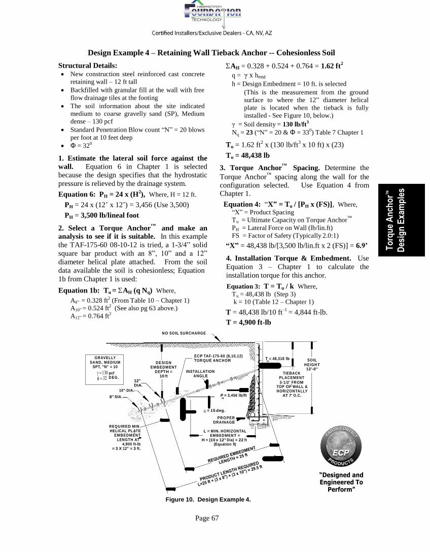
Design Example 4 – Retaining Wall Tieback Anchor -- Cohesionless Soil
Structural Details: New construction steel reinforced cast concrete
retaining wall – 12 ft tall
Backfilled with granular fill at the wall with free
flow drainage tiles at the footing
The soil information about the site indicated medium to coarse gravelly sand (SP), Medium
dense – 130 pcf
Standard Penetration Blow count “N” = 20 blows
per foot at 10 feet deep
Φ = 320
1. Estimate the lateral soil force against the
wall. Equation 6 in Chapter 1 is selected because the design specifies that the hydrostatic
pressure is relieved by the drainage system.
Equation 6: PH = 24 x (H2), Where, H = 12 ft.
PH = 24 x (12’ x 12’) = 3,456 (Use 3,500)
PH = 3,500 lb/lineal foot
2. Select a Torque Anchor™
and make an analysis to see if it is suitable. In this example
the TAF-175-60 08-10-12 is tried, a 1-3/4” solid
square bar product with an 8”, 10” and a 12”
diameter helical plate attached. From the soil
data available the soil is cohesionless; Equation
1b from Chapter 1 is used:
Equation 1b: Tu = AH (q Nq) Where,
A8” = 0.328 ft2
(From Table 10 – Chapter 1)
A10” = 0.524 ft2
(See also pg 63 above.)
AH = 0.328 + 0.524 + 0.764 = 1.62 ft2
q = γ x hmid
h = Design Embedment = 10 ft. is selected
(This is the measurement from the ground
surface to where the 12” diameter helical
plate is located when the tieback is fully
installed - See Figure 10, below.)
γ = Soil density = 130 lb/ft3
Nq = 23 (“N” = 20 & Φ = 330) Table 7 Chapter 1
Tu = 1.62 ft2
x (130 lb/ft3
x 10 ft) x (23)
Tu = 48,438 lb
3. Torque Anchor™
Spacing. Determine the
Torque Anchor™
spacing along the wall for the configuration selected. Use Equation 4 from Chapter 1.
Equation 4: “X” = Tu / [PH x (FS)], Where,
“X” = Product Spacing
Tu = Ultimate Capacity on Torque Anchor™
PH = Lateral Force on Wall (lb/lin.ft) FS = Factor of Safety (Typically 2.0:1)
“X” = 48,438 lb/[3,500 lb/lin.ft x 2 (FS)] = 6.9’
4. Installation Torque & Embedment. Use
Equation 3 – Chapter 1 to calculate the
installation torque for this anchor.
Equation 3: T = Tu / k Where,
Tu = 48,438 lb (Step 3)
k = 10 (Table 12 – Chapter 1) -1
A12” = 0.764 ft2
T = 48,438 lb/10 ft
T = 4,900 ft-lb
= 4,844 ft-lb.
N O S O IL S U R C H A R G E
G R AVELLY S A N D , M E D IU M
SPT, "N" = 10
pcf
D E G .
12"
D E S I G N
E M B E D M E N T D E P T H =
10 ft
EC P TA F-175-60 (8,10,12) TO R Q U E A N C H O R
INSTALLATION
A N G LE
T = 48,318 lb
U
TIEBACK
P L A C E M E N T 3-1/2' FR O M
S O IL
H E I G H T 12'-0"
10" DIA.
8" DIA.
DIA. P = 3,456 lb/ft H
TOP OF WALL & H O R IZ O N TA LLY
AT 7' O.C.
R E Q U IR E D M IN . HELICAL PLATE
E M B E D M E N T LENGTH AT
4,900 ft-lb = 3 X 12" = 3 ft.
= 15 deg.
P R O P E R D R A IN A G E
L = M IN. HORIZONTAL
E M B E D M E N T = H + (10 x 12" Dia) = 22 ft
(Equation 9)
Figure 10. Design Example 4.
“Designed and Engineered To
Perform”

Page 68
The torque must be developed for a distance
great enough to insure that the helical plates are
properly embedded to develop adequate tension
capacity. The torque requirement must be
averaged over a minimum distance of at least
three times the diameter of the largest plate. The
Where: LTip = (3 x dplate 1) + (3 x dplate 2)
LTip = [(3D x 8” dia)+(3D x 10” dia)]/12 LTip = 4-1/2 ft L = L15 + LTip = 25 ft + 4-1/2 ft = 29-1/2 ft
L = 29-1/2 feet α = 150
™
installer must average at least 4,900 ft-lbs 6. Torque Anchor Capacity Verification: A
through a distance of 3 feet. (Three times the review of Table 2 – Chapter 1 indicates that the ™
12” diameter plate.) 1-3/4” solid square bar Torque Anchor has a
5. Select Installation Angle and Product Length. The anchors penetrate the wall at 3-1/2 feet below the soil surface. (This is
approximately 0.3 times the wall height.) Recall that embedment depth was selected at 10 ft in Step 2. This means that the depth below the soil surface to the location of the 12” helical plate must be at least 10 feet. Try using an
installation angle of 150
and determine the
product length that will provide the 10 feet of vertical embedment required. (The required depth of embedment is 10 ft. Recall that the
Ultimate Limit Tension Strength of 100,000 lb and a Useable Torsional Strength of 10,000 ft-lb.
The project ultimate tension capacity and
torsional requirement are approximately one-half
of the mechanical and torsional capacity of the
product. There was no mention about rocks,
debris or other obstructions in the soil so
installation should be smooth. A check of Table
11 – Chapter 1 indicates that three 3/8” thick
helical plates have an ultimate capacity of
120,000 pounds (3 x 40,000 lb), so the total
mechanical capacity of the anchor is satisfactory.
™
distance from the top of grade level to where the
anchors will penetrate the wall is 3-1/2 feet. The
7. Torque Anchor required Torque Anchor
™
Specifications. The assembly consists of:
additional depth required by the anchor is 6-1/2 feet (10 ft - 3-1/2 ft) = 6-1/2 feet.)
The shaft length required at 150
to achieve the 6-
1/2 foot vertical depth is calculated using the
equation given in Table 13 in Chapter 1 for a
declination angle of 150.
L15 = (6-1/2 ft/sine 150) = 6-1/2 ft/0.259 = 25 ft
The minimum shaft length at 150
installation
angle is 25 feet, which will insure that the 12”
diameter plate is located at a total embedment
depth of 10 feet below the surface.
Comparing the Minimum Horizontal Embedment
length from Equation 9 to the Minimum
Embedment Depth (Step 5):
TAF-175-84 08-10-12 - 1-3/4” solid square bar, on a standard 7’ long shaft with 8”, 10”
& 12” dia. plates,
TAE-175-84 extensions - 7 feet long &
hardware (6’-9” effective length) – Three
extensions are required.
TAE-175-60 extensions - 5’ long with
hardware (4’-9” effective length) – One
extension is required.
TAB-175 T Tension Pile Cap – 3/4” x 8” x
8” pile cap with bolt and nut. The pile cap
bolts to the anchor shaft and will be incorporated into the concrete new construction wall.
The actual assembled length of the specified ™
L0 = 12 + [10 x 1’] = 22 ft. Torque Anchor system is 32 ft.
It is clear that L15 = 25 ft (Length to insure
required 10’ soil embedment depth determined in Step 5) exceeds the Minimum Horizontal Embedment requirement.
The 10 ft depth of embedment also exceeds the
Critical Depth, “D” = 6 x d12 = 6 x 12”/12 = 6 ft
L15 = 25’ > L0 = 22’ using D = 6
Use L15 = 25 ft
Minimum Required Shaft Length:
L = L15 + LTip (Distance shallowest plate to tip)
The anchors shall mount along the wall at 7 feet center to center at a distance of 3-1/2 feet from the top of the proposed wall. The anchors shall
be installed at a downward angle of 150
from
horizontal. The tiebacks must be installed to a length greater than 29-1/2 feet and must develop an average installation torque of 4,900 ft-lb or more for a minimum distance of at least 3 feet beyond an installed length of 26 feet, otherwise the anchor shall be driven deeper until this
torque requirement is satisfied.
End of Example 4

Page 69
Slab Floor, Carpet & Pad 195 Wood Frame Walls – 2 Story 176 2
nd Floor – 14’ Span, Carpet & Pad 98
Roof – 6” in 12” Composition, 14’ Span 171
To
rqu
e A
nch
or™
Des
ign
Exa
mp
les
Design Example 5 – Foundation Restoration – Cohesive Soil
Structural Details: Two story wood frame house with wood
composition siding.
Foundation consists of 20” wide by 18” tall steel
reinforced concrete perimeter beam with a 4”
thick concrete slab cast with the perimeter beam.
The corner of structure has settled 2”
Top of pile will be 12” below the soil surface
Soil data: There are two feet of consolidating,
poorly compacted fill overlaying 20 feet of
inorganic clay (CL), stiff.
SPT “N” blow count was measured between 8 to
12 blows per foot increasing with depth
Torque Anchor™
Design:
1. Determine the foundation load: Breaking
MONOLITHIC CONCRETE
FOUNDATION:
18" X 20" BEAM & 4" SLAB
2 FEET OF POORLY
COMPACTED AND
CONSOLIDATING
FILL MATERIAL
ULT. CAP. = 18,750 lb
WORKING LOAD = 9,375 lb
ANCHOR BOLT
(OPTIONAL)
MODEL TAB-150
UTILITY BRACKET
down weights of structural elements can be
found in the Simplified Tables of Structural
Foundation Loads in Tables 2 through 9 in ™
TAE-150-60 EXTENSIONS
(2 REQUIRED)
TAF-150-60 (12-14)
HELICAL LEAD
13' = DEPTH
TO MID
PLATES
Chapter 5, ECP Steel Piers Design, later in this 14-1/2'
manual. The foundation loads are estimated
below:
Footing – 20” x 18” 360 lb/lf
14" DIA.
20 FEET OF INORGANIC
CLAY -- FIRM TO STIFF
STP BLOW COUNTS --
"N" = 8 TO 10
12" DIA.
Total Dead Load 1,000 lb/lf
Live Load – Slab 120 nd
Live Load – 2 Floor, 14’ Span 180 Figure 13. Design Example 5.
Total Live Load 300 lb/lf
w = Distributed Load = 1,000 + 300 = 1,300 lb/lf
w = 1,300 lb/lineal foot
2. Select a Suitable Pile Spacing and
Determine Ultimate Torque Anchor™
Load: This is not a heavy structure, so for economy the
solid square bar Torque Anchor™
configuration is chosen for this restoration along with Utility Brackets to transfer the structural load to the pile
FS = Factor of Safety (Use 2.0)
Pu = 7-1/2 ft x 1,300 lb/ft x 2 = 19,500 lb
3. Determine the helical plate area required from the known information: Because the soil on the site is cohesive, Equation 1a from Chapter
1 is used:
Equation 1a: AH = Pu / (9c) Where:
Pu = 19,500 lb (Step 2) 2
shaft. Using Graph 2 in Chapter 5, select pile c = 1,250 lb/ft Average “N” = 10 (assumed)
spacing, “X”, at 7-1/2 feet on the perimeter beam. (Note arrow on
graph.) Determine the working
load on the piles from Equation 4
– Chapter 1.
Equation 4. Pu = “X” x w x (FS):
Where,
“X” = Product Spacing = 7-1/2
feet (Selected)
w = 1,300 lb/lineal foot (Step 1)
18"
16" 14" 12"
BEAM HEIGHT
4 - #4 REBARS (GR-60)
3
(Table 5 - Chapter 1)
4 5 6 7
PIER SPACING - feet
EXAMPLE 5

Page 70
AH = Pu / (9 x 1,250) = 19,500 lb / 11,250 lb/ft2
AH = 1.73 ft2
that the pile would reach the desired shaft torsion
at a mid-plate depth of about 13 feet.
Minimum Required Shaft Length: 4. Select the ECP Helical Torque Anchor
™ L = h
mid + LTip - hF
suitable to support the load.
Referring to Table 2 – Chapter 1 the 1-1/2” solid
square pile shaft is selected. It has an Axial
Compression Load Limit rating of 70,000 pounds
Where:
hmid = 13 ft (The depth from the surface to
midway between plates on the shaft.)
LTip = (3DPlate 1) / 2 and a Useable Torsional Strength of 7,000 ft-lbs.
Referring to Table 10 – Chapter 1, we will select
LTip
= (3 x 12” dia / 2 = 18 in
our combination of plates from the list opposite
the 1-1/2” shaft size. We must provide at least
1.67 ft2
of bearing area:
6” Dia. = 0.181 ft2
8” Dia. = 0.333 ft2
10” Dia. = 0.530 ft2
12” Dia. = 0.770 ft2
14” Dia. = 1.053 ft2
The combination of 12” & 14” diameter plates
on the 1-1/2” solid square shaft provides a total
area of 1.82 ft2.
TAF-150-60 12-14
5. Installation Torque. Use Equation 2 –
Chapter 1 to calculate the installation torque for
this anchor.
T = Tu / k Where,
Tu = 19,500 lb (Step 2)
k = 10 (Table 12 – Chapter 1)
T = 19,500 lb / 10 ft-1
T = 1,950 ft-lb – Use 2,000 ft-lb
6. Torque Anchor™
Capacity Verification: A
review of Table 2 – Chapter 1 indicates that the
1-1/2” solid square bar Torque Anchor™
has a
Useable Torsional Strength of 7,000 ft-lb, which
is more than adequate for this application. The product selection should work based upon the soil report stating that the firm to stiff clay
becomes more dense as the depth increases.
There was no mention of rocks, debris or other obstructions. Table 11 – Chapter 1 verifies that
two 3/8” thick helical plates have a mechanical
ultimate capacity of 80,000 pounds. The
mechanical capacity of the pile is excellent.
7. Installed Product Length. Termination
depth is targeted in the stiff silty clay where the
helical plates will be situated. The data indicates
that the soil has a variance in the Standard
Penetration Test (SPT) blow count, “N”,
between 8 and 12 blows per foot. It is estimated
LTip = 1-1/2 ft
hF = -1 ft (The pile cap will terminate at the
Utility Bracket approximately 12
inches below grade level.)
L = 13 ft + 1-1/2 – 1 ft
L = 13-1/2 feet = Shaft length estimate
8. Torque Anchor
™ Specifications: Specify
the necessary Torque Anchor™
components:
TAF-150-60 12-14 - 1-1/2” solid square bar
lead section on a standard length 5 feet long
shaft with a 12” and 14” diameter plate.
TAE-150-60 Extension – 1-1/2” solid square
bar extension 5 feet long with hardware, 2
required (The coupling overlaps 3 inches
providing an effective length of 4’-9”)
TAB-150-SUB-150 Utility Bracket. This foundation bracket fits over the 1-1/2” square bar and mounts to the perimeter
beam. The bearing plate provides 68-1/4 in2
at the bottom of the foundation for load transfer.
The total length of the assembled Torque
Anchor™
is 14-1/2 ft.
The Torque Anchors™
shall be spaced at 7-1/2
feet center to center along the perimeter grade
beam and must develop an average installation
torque of 2,000 ft-lb or more during the last 3
feet of the installation. Depth is 13-1/2 feet.
Note: It is recommended to order additional
extension sections because the target torque
might not be achieved at 13-1/2 feet.
9. Foundation Restoration. Once all of the
Torque Anchor™
piles have been installed and the Utility Brackets mounted, the structure may be restored to as close to the original elevation as the construction will permit.
A pile cap, lift assembly and hydraulic jack
are installed at each placement.

Page 71
To
rqu
e A
nch
or™
Des
ign
Exa
mp
les
All hydraulic jacks are connected to a hand
pump and gauge through a manifold system
that distributes equal pressure to all jacks.
The hand pump is actuated, transferring the structural load from the soil below the
footing to the Torque Anchor™
shafts. As the structure responds and a portion of the foundation reaches the desired elevation, the jack(s) supporting the restored area(s) are isolated and the pressure at the jack(s) recorded.
The restoration process continues until the structure is satisfactorily restored, and all
jacks have been isolated and their pressures
recorded.
All installation and restoration data is
transferred to a Project Installation Report.
This report should include, but is not
limited to, project identification, equipment
used, product installed, final installation
torque, installed depth, lifting force
required to restore the structure and lift
measurement. This data must be recorded
for each placement.
Review the report and calculate actual
factors of safety on the installation to see if
the design requirements have been
satisfied.
10. Actual Load vs. Calculated Load and
Installed Factor of Safety: The installation
data must be compared to the calculated values.
This enables the designer to verify the accuracy
of the design. In addition, actual project factors
of safety should be verified, as shown below.
The actual factor of safety for each pile
installation is calculated, a slight variation of the
typical factor of safety formula is used.
Equation 12: Project Factor of Safety
FSjob = Pu-job / Pw-job
Where:
Pu-job = Installed Estimated Ult. Capacity – lb
(Pu-job = Installation Torque x k)
Pw-job = Lifting Force to Restore – lb
(Pw-job = Jack Pressure x Cylinder Area)
The Project Installation Report data is used to calculate the actual factors of safety for each
Torque Anchor™
placement:
FSActual = TFinal x k (Table 12)/ PLift
Pile 1: FS = (2,000 ft-lb x 10 ft-1
) lb / 9,000 lb
FSpile 1 = 2.22
Pile 2: FS = (1,950 ft-lb x 10 ft-1
) lb / 9,400 lb
FSpile 2 = 2.07
Pile 3: FS = (2,050 ft-lb x 10 ft-1
) lb / 7,700 lb
FSpile 3 = 2.66
PROJECT INSTALLATION REPORT
Project Name: Design Example 5
Project Address: 123 Anywhere, Mid-America, USA
Products Installed: TAF-150-60 10-12 Lead TAE-150-60 Extensions TAB-150-SUB Utility Bracket
Torque Motor: Model LW6K – 6,000 ft-lb
Lifting Jack: Model RC254 – 25 Ton
Calculated Ultimate Pile Capacity: Pu = 19,500 lb Calculated Working Pile Load: Pw = 9,750 lb Placement Identification Pile 1 Pile 2 Pile 3 Final Install Torque, ft-lb 2,000 1,950 2,050 Pile Depth, ft 18.5 16 16.5 Force to Lift, lb 9,000 9,400 7,700 Amount of Lift, in 1-1/2 1-3/4 2 Actual Factor of Safety 2.22 2.07 2.66
Soil tends to be non-homogeneous and normally
installation torque varies from point to point on a
project; in addition, the load on a footing is
usually not uniform due to different architectural
elements in the design of the structure. Pile 2
had slightly lower shaft torsion than required and
had a slightly higher working load. This resulted
in the lowest Factor of Safety. Pile three was on
a lightly loaded part of the building an had a
large Factor of Safety.
End Design Example 5
Review of Results of Example 5
Comparing the calculated design working load of 8,818 lb per pile (Pw = w (Step 1) x “X” (Step 2) =
1,300 lb/ lineal ft x 7-1/2 ft = 9,750 lb) to the actual lifting forces one can see that all working pile
loads are slightly lower than predicted by the calculations. These differences between calculated and
actual working loads are not significant and are related to the fact that actual loads on the footing are
not uniform along the footing. The actual factors of safety for the installation on this project
demonstrate that the project has actual factor of safeties within normal tolerances. The project has a
safe design.

Page 72
Table 2. Ranges for Typical Average Residential Building Loads
Building Construction (Slab On Grade)
Estimated Foundation Load Range
(DL = Dead – LL = Live)
One Story Wood/Metal/Vinyl Walls with Wood Framing -- Footing with Slab
DL 750 – 850 lb/ft LL 100 – 200 lb/ft
One Story
Masonry Walls with Wood Framing – Footing with Slab
DL 1,000 – 1,200 lb/ft LL 100 – 200 lb/ft
Two Story Wood/Metal/Vinyl Walls with Wood Framing – Footing with Slab
DL 1,050 – 1,550 lb/ft LL 300 – 475 lb/ft
Two Story
1st Floor Masonry, 2nd Wood/Metal/Vinyl with Wood Framing – Footing with Slab
DL 1,300 – 2,000 lb/ft LL 300 – 475 lb/ft
Two Story
Masonry Walls with Wood Framing – Footing with Slab
DL 1,600 – 2,250 lb/ft LL 300 – 475 lb/ft
Design Example 5A – Foundation Restoration – “Quick and Rough” Method
Design Details from Design Example 5:
Two story wood frame house with slab
foundation and wood composition siding.
Foundation consists of 20” wide by 18” tall steel
reinforced concrete perimeter beam
Top of pile to be 12” below the soil surface
Soil data: Two feet of consolidating poorly
compacted fill was found overlaying 20 feet of
inorganic clay (CL), firm to stiff.
ECP Torque Anchor™
Design:
1. Determine the foundation load: Use Table
2, Ranges for Typical Average Residential
Building Loads that can be found in Chapter 5 of
this manual. A portion of Table 2 from Chapter
5 is shown below. (This table does not include
snow loads. Snow loads must be added for the
job location.)
From the description of the project, the total
foundation load (except snow loads) can be
roughly estimated for this structure from Table 2.
The portion of Table 2 reproduced is for slab on
grade foundation loads, which is the type of
foundation on this project that
other column provides a range of foundation
dead load weights for this kind of residential
structure. Dead loads range between 1,050 and
1,550 lb/lin.ft and the live load estimates run
from 300 to 475 lb/lin.ft.
A judgment about the quality of construction is used to select the foundation loads from within
the ranges. For Design Example 5A careful
judgment about the construction suggests using
DL = 1,200 lb/lin.ft and LL = 375 lb/lin.ft. The
average perimeter loading to be used for the
“Quick and Rough” design is 1,575 lb/lin.ft.
2. Determine the Soil Class. The soil was
reported only as still clay. Referring to the Soil
Classification Table - Table 9 (Chapter 1), Soil
Class 6 is selected. Keep in mind that little soil
information available and there is concern about
the poorly compacted fill near the surface.
3. Select a Suitable Pile Spacing and
Determine Ultimate Torque Anchor™
Load: This is not a heavy structure so the solid square
bar Torque Anchors™
configuration is chosen for this restoration along with Utility Brackets are the most economical products to use to transfer the structural load from the foundation to the pile shaft. Use Graph 2 from Chapter 6, to select pile spacing, “X”. (See below)
A loading of 1,575 lb/lin. ft is slightly higher
than the 1,500 lb/ft line on the graph. This line
will be used to select the spacing and then the
spacing will be adjusted to reflect the load higher
than the graph curve. Read across from the 18
inch footing height to an estimated 1,575 lb/ft
position, then drop down to see the pile spacing
of 6-3/4 feet. 6-3/4 feet center to center is
selected for “Safe Use” design.
“X” = 6-3/4 feet
supports a two story residence
that has wood composition
siding.
To determine the estimated
foundation load, look down the
first column until the “Two
Story” description that most
closely matches the job house is
found. Reading across to the
18"
16" 14" 12"
BEAM HEIGHT
4 - #4 REBARS (GR-60)
3
4 5 6 7
PIER SPACING - feet
EXAMPLE 5

Page 73
1 2 3 4 5 6
E
sti
ma
ted
Ult
ima
te C
ap
acit
y To
rqu
e A
nch
or™
Des
ign
Exa
mp
les
4. Determine Ultimate Torque Anchor™
Load:
Use Equation 3 from Chapter 1 to determine the ultimate capacity per pile:
Equation 3. Pu = (“X”) x (w) x (FS):
Where,
“X” = Product Spacing = 6-3/4 feet
w = 1,575 lb/lineal foot (Step 1) FS = Factor of Safety (Use 2.0)
Pu = 6-3/4 ft x 1,575 lb/ft x 2 = 21,263 lb
5. Select the proper pile configuration: Referring to Graph 4 from Chapter 1 (reproduced
below), notice that the capacity line for 12” and
14” diameter helical plates attached to shaft
crosses just above 20,000 pounds at the center of
Soil Class 6. The 12” and 14” diameter plate
configuration is selected for the design.
7. Installation Torque. Use Graph 6 from Chapter 2, shown next page to determine the
installation torque requirement for the piles. The
Ultimate Capacity requirement is 21,263 pounds.
Find 22,000 pounds at the left side of Graph 6
look horizontally to the graph line for solid
square shafts, read down to torque of 2,200 ft-lb.
T = 2,200 ft-lb, minimum
Just for comparison, the installation torque is
calculated: from Equation 2 in Chapter 1:
Equation 2: T = Pu / k, (from Chapter 1)
Pu = 21,263 lb k = 10 (Table 12)
T = 21,263 lb/10 ft-1
= 2,127 ft-lb T = 2,200 ft-lb
8. Installed Product Length. Termination
depth is the stiff clay. It is likely that the pile
120000
TORQUE ANCHOR HOLDING CAPACITY Multiple Helic al Plate Sizes
12-14" 8-10-12" 10-12-14" 12-14-14"
100000
80000
60000
40000
20000
0
Gr aph 4. 7 6 5 4 3
S oil Classification
6. Check Shaft Strengths and Torsional
Strengths to see which shaft is suitable: Refer
to Table 2 in Chapter 1 to find a shaft with a
suitable Axial Compression Load Limit and
sufficient Useable Torsional Strength. The 1-1/2
inch solid square shaft is selected because it has
an Axial Compression Load Limit rating of
70,000 pounds based upon an installation
torsional limit of 7,500 ft-lbs. This pile exceeds
the ultimate job load requirement of 21,263
pounds. The selected and verified pile
configuration is TAF-150-60 12-14.
would reach the desired shaft torsion at a depth
somewhere beyond the unconsolidated soil near
grade. The minimum depth is the summation of
the Critical Depth (Chapter 1, page 16) plus the
distance to the lowest plate.
Minimum Required Shaft Length:
Lmin = DCritical + LTip Where:
DCcritical = 14” dia./12” x 6 ft (Page 16) (Critical Depth = 6 x diameter of largest plate.)
LTip = 12” dia./12” x 3 = 3 ft (Plates spaced at 3 x diameter.)
Lmin = (14”/12” x 6’) + (12”/12” x 3) = 10 ft
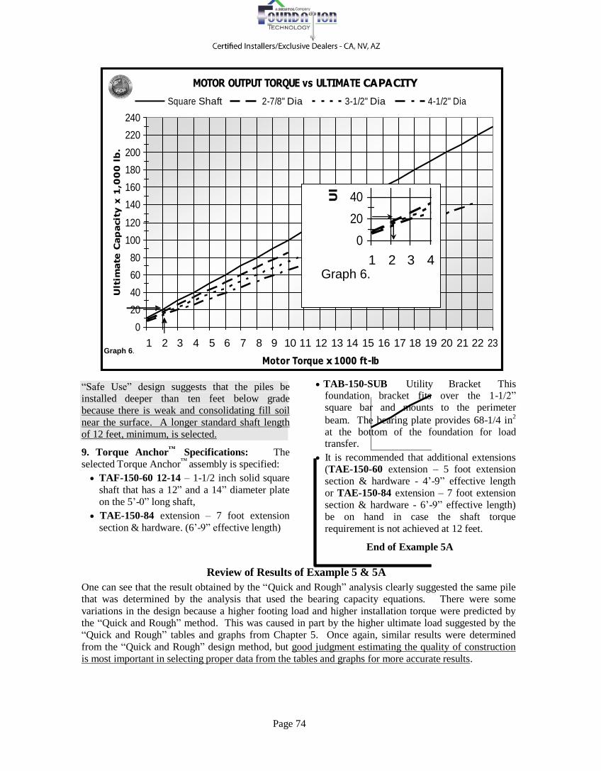
Page 74
Ult
ima
te C
ap
acit
y x
1,0
00
lb
.
Ul
240
220
200
180
160
140
120
100
80
60
40
20
0
Graph 6.
MOTOR OUTPUT TORQUE vs ULTIMATE CAPACITY
Square Shaft 2-7/8" Dia 3-1/2" Dia 4-1/2" Dia
40
20
0
1 2 3 4 Graph 6.
1 2 3 4 5 6 7 8 9 10 11 12 13 14 15 16 17 18 19 20 21 22 23
Mot or Torque x 1000 ft -lb
“Safe Use” design suggests that the piles be installed deeper than ten feet below grade
because there is weak and consolidating fill soil
near the surface. A longer standard shaft length
of 12 feet, minimum, is selected.
9. Torque Anchor™
Specifications: The
selected Torque Anchor™
assembly is specified:
TAF-150-60 12-14 – 1-1/2 inch solid square
shaft that has a 12” and a 14” diameter plate
on the 5’-0” long shaft,
TAE-150-84 extension – 7 foot extension
section & hardware. (6’-9” effective length)
TAB-150-SUB Utility Bracket This foundation bracket fits over the 1-1/2” square bar and mounts to the perimeter
beam. The bearing plate provides 68-1/4 in2
at the bottom of the foundation for load transfer.
It is recommended that additional extensions (TAE-150-60 extension – 5 foot extension
section & hardware - 4’-9” effective length
or TAE-150-84 extension – 7 foot extension
section & hardware - 6’-9” effective length)
be on hand in case the shaft torque
requirement is not achieved at 12 feet.
End of Example 5A
Review of Results of Example 5 & 5A
One can see that the result obtained by the “Quick and Rough” analysis clearly suggested the same pile
that was determined by the analysis that used the bearing capacity equations. There were some
variations in the design because a higher footing load and higher installation torque were predicted by
the “Quick and Rough” method. This was caused in part by the higher ultimate load suggested by the
“Quick and Rough” tables and graphs from Chapter 5. Once again, similar results were determined
from the “Quick and Rough” design method, but good judgment estimating the quality of construction
is most important in selecting proper data from the tables and graphs for more accurate results.

Page 75
Table 16. Hydraulic Torque Motor Specifications
Illustration
Model
Number
Torque Output
ft-lb
Motor Torque
Conversion Factor – “K”
Maximum Pressure
psi
PRO-DIG
L6K5
6,335 2.53
2,500
L7K5
7,644
2.55
3,000
X9K5
9,663
3.22
3,000
X12K5
12,612
4.20
3,000
T12K 5,597/ 12,128
2.24/4.85
2,500
To
rqu
e A
nch
or™
Des
ign
Exa
mp
les
Design Example 6 – Motor Output Torque
The heavy weight new construction pile design presented in Design Example 1 required shaft torsion of 7,100 ft-lb be applied to the 2-7/8 inch
diameter Torque Anchor™
shaft to achieve the
ultimate capacity requirement of 60,000 pounds. In Design Example 1B, where weak soil was present, the torsion requirement was determined to be 8,000 ft-lb on a 3-1/2 inch diameter tubular shaft to be able to achieve the same 60,000 pound ultimate pile capacity.
Project Details Provided from the Field:
New Building – 2 story house with basement
Ultimate Capacity = 60,000 lb
Torque Motor Available = Pro-Dig X12K5
Design 1 – Avg. Pressures at termination depth -
2-7/8” dia = 1,900 psi at inlet & 200 psi at outlet
Design 1B – Avg. pressures at termination depth,
3-1/2” dia = 2,150 psi at inlet & 200 psi at outlet
Pressures averaged over final three feet of depth
Equation 11 introduced in Chapter 2 is used to
convert pressure differential across the hydraulic
gear motor into shaft output torque.
Equation 12: Motor Output Torque
T = K x ∆P
1. Differential Pressures: Before using
Equation 11, the pressure differential, or ∆P,
from the field must be determined.
The Motor Torque Conversion
Factor – “K” must also be
identified for the Pro-Dig X12K5.
The Pressure Differential across
the motor is determined as
follows:
∆P = Inlet psi – Outlet psi
∆P = pin – pout
∆P from Design Example 1:
∆PExample 1 = 1,900 psi – 200 psi
∆PExample 1 = 1,700 psi
∆P from Design Example 1B:
∆PExample 1B = 2,150 psi – 200 psi
∆PExample 1B = 1,950 psi.
2. Motor Torque Conversion Factor, “K”: The Motor Torque Conversion
Factor – “K” is found on Table 16 in Chapter 2.
(A portion of the table is shown below.)
Looking in the “Model Number” column of
Table 16, the X12K5 Torque Motor data is
found. Reading to the right the value for the
Motor Conversion Factor, “K”, for this motor is
determined to be “K” = 4.20.
3. Motor Output Torque: Once the differential
pressure across the hydraulic torque motor has
been calculated (Step 1) and the value for “K”
determined (Step 2), the values can be used in
Equation 11 to determine the actual torque that
was applied to the pile shaft at termination depth.
Equation 11: Motor Output Torque
T = K x ∆P
Where,
T = Hydraulic Motor Output Torque - ft-lb
K = Torque Motor Conversion Factor – (Table 16)
∆P = pin – pout = Motor Pressure Differential
Confirm proper installation torque for Design
Example 1.
T Example 1 = 4.20 x 1,700 psi
T Example 1 = 7,140 ft-lb
7,140 ft-lb > 7,100 ft-lb - O.K.
Confirm proper installation torque for Design
Example 2.
T Example 1B = 4.20 x 1,950
T Example 1B = 8,190 ft-lb
8,190 ft-lb > 8,000 ft-lb - O.K.
End Design Example 6

Page 76
Ou
tpu
t T
orq
ue
at
Sh
aft
(ft
-lb
)
Design Example 6A – Motor Output Torque “Quick and Rough Method”
The heavy weight new construction pile design presented in Design Example 1 specified that when installed on the site, torsion of 7,100 ft-lb was needed on the 2-7/8 inch diameter Torque
Anchor™
shaft to reach the ultimate capacity requirement of 60,000 pounds.
In Design Example 1B where weak soil was
present the torsion requirement increased to
8,000 ft-lb on the 3-1/2 inch diameter tubular
shaft to achieve the same 60,000 pound ultimate
pile capacity.
Determine Motor Output Torque: Graph 9
introduced in Chapter 2 is used to convert
pressure differential across the hydraulic gear
motor into shaft output torque. Referring to
Graph 9 (reproduced below); the output torque of
the X12K5 motor can be determined once the
pressure differentials across the installation
motor are determined.
∆P = Inlet psi – Outlet psi
∆P = pin – pout
∆P from Design Example 1:
∆PExample 1 = 1,900 psi – 200 psi
∆PExample 1 = 1,700 psi
∆P from Design Example 1B:
∆PExample 1B = 2,150 psi – 200 psi
∆PExample 1B = 1,950 psi
With the actual field measured pressure
differentials calculated, one can find the actual
installation motor torque at pile termination
depth on Graph 9. Locate 1,700 psi and 1,950
psi values at the bottom of the graph. Then read
upward until the motor curve line for the X12K5
motor is reached. Read horizontally to the left
where the Output Torque at the Shaft” where can
be found.
Design Example 1 output shaft torsion is
determined to be estimated at 7,250 ft-lbs.
Design Example 1B had a pressure differential of
1,950 psi pressure differential, which produced
an output torque estimated at 8,200 ft-lb.
Proper installation shaft torque is confirmed for
Design Examples 1 and 1B
End Design Example 6A
13,000
12,000
11,000
10,000
9,000
8,000
7,000
6,000
5,000
4,000
3,000
2,000
1,000
GRAPH 9. PRO-DIG SINGLE SPEED GEAR M OTORS - DIFFERENTIAL
PRESSURE AT M OTOR VS. M OTOR OUTPUT TORQUE FOR
Pro-Dig L7K5 Pro-Dig X9K5 Pro-Dig X12K5 5 6 7 8 9 10 11 12 13 14 15 16 17 18 19 20 21 22 23 24 25 26 27 28 29 30
Pressure Different ial A cross Mot or x 100 (psi)
Review of Results of Example 6 & 6A
One can see that the result obtained by the “Quick and Rough” analysis suggested the shaft torsion
from field data was sufficient to provide the load capacity. The calculated method and the “Quick and
Rough” solutions for the actual installation shaft torque values were similar.

Page 77
To
rqu
e A
nch
or™
Des
ign
Exa
mp
les
Design Example 7 – Ultimate Capacity from Field Data
In this exercise the anticipated ultimate
capacities of the pile designs from Design
Example 1 and 1B will be determined. This
information will be used to confirm that the
installed piles meet or exceed the design
requirements set out in the original designs
Equation 2 from Chapter 1 is used to calculate
the ultimate compressive capacity of the pile
based upon data provided from the field. Recall
that the Design Example 1 - Heavy Weight New
Construction Project required an ultimate
capacity at each pile of 60,000 pounds.
Equation 2: Helical Pile Ultimate Capacity
Pu = k x T
Where,
Pu or Tu = Ult. Capacity of Torque Anchor™
- (lb)
T = Final Installation Torque - (ft-lb)
(Averaged Over the Final 3 to 5 Feet)
k = Empirical Torque Factor - (ft-1
)
Calculating the ultimate pile capacity using data
from Design Example 1:
Ultimate Capacity of the 2-7/8” diameter, 0.262
wall piles installed in Example 1 (Pu-Example 1):
Where,
k = 8.5 (Table 12)
TExample 1 = 7,140 ft-lb (Design Example 6)
Pu = 8.5 x 7,140 = 60,690 lb
Pu = 60,690 lb > 60,000 lb O.K.
Calculating the ultimate pile capacity using data
from Design Example 1B:
Ultimate Capacity of the 3-1/2” diameter piles
with 0.300 inch wall thickness that were installed
in Design Example 1B = Pu-Example 1B:
Where,
k = 7.5 (Table 12)
TExample 1B = 8,190 ft-lb (Design Example 6)
Pu = 7.5 x 8,190 = 61,425 lb
Pu = 61,425 lb > 60,000 lb O.K.
The results of the calculations confirm the
ultimate capacity determined from the field data
exceeds the design ultimate capacity stated in the
specifications of Design Examples 1 and 1B.
End Design Example 7
Design Example 7A – Ultimate Capacity from Field Data – “Quick and Rough” Method
This exercise will determine the ultimate pile
capacity based upon field data using the “Quick
and Rough” method. The comparison between
the calculated design specifications and the
actual field capacity will verify whether the pile
installation is satisfactory.
Design Example 6A determined that the output
torque at the motor shaft was 7,250 ft-lb at the
termination of the pile installation. Graph 7
from Chapter 2 (shown on the next page)
provides a method to demonstrate the ultimate
capacity of the installed helical product. A
comparison to the design requirement will
determine if the installed pile capacity exceeds
the specified ultimate capacity.
Estimate the location on the horizontal axis for
shaft torsion of 7,250 ft-lb slightly to the right of
the 7,250 ft-lb grid line and read up to the plot
line for the 2-7/8 inch diameter shaft
configuration. The legend near the top of the
graph provides choices between square shafts
and various tubular shafts. Read upward from
the 7,250 ft-lb “Motor Torque” line until the
bold dashed line that represents the 2-7/8 inch
diameter shaft configuration is encountered.
Then move horizontally to the vertical axis at left
to see if installed pile ultimate capacity exceeds
60,000 pounds.
Looking carefully at the point where the
horizontal plot intersects the “Ultimate
Capacity” axis, the field generated shaft torsion
at the termination of the pile installation shows
to be slightly above 60,000 lb. This verifies that
the actual installed pile capacity exceeds design
specifications.
End Design Example 7
Review of Results of Example 7 & 7A
The value in using the “Quick and Rough” method is that it provides rapid results from the graphs. This method cannot tell exactly how much the field installation exceeded the design requirements, but
it confirms whether the installation meets or exceeds specificaitons. If the engineer wants to know the
actual installed ultimate capacity, then it must be calculated.

Page 78
Ult
ima
te C
ap
acit
y x
1,0
00
lb
.
240
220
200
180
160
140
120
100
80
60
40
20
0
MOTOR OUTPUT TORQUE vs ULTIMA TE CA PA CITY
Square Shaft 2-7/8" Dia 3-1/2" Dia 4-1/2" Dia
1 2 3 4 5 6 7 8 9 10 11 12 13 14 15 16 17 18 19 20 21 22 23
Mot or Torque x 1000 ft -lb
Technical Design Assistance Earth Contact Products, LLC. has a knowledgeable staff that stands ready to help you with understanding how to prepare preliminary designs, installation procedures, load testing, and
documentation of each placement when using ECP Torque Anchors™
. If you have questions or require engineering assistance in evaluating, designing, and/or specifying Earth Contact Products, please call us at 913 393-0007, Fax at 913 393-0008.