helical hydraulic rotary actuators - helac corporation...mark timing between piston sleeve and shaft...
TRANSCRIPT

Helical Hydraulic Rotary ActuatorsT30-27 Service & Repair Manual

2 Parker Hannifin CorporationHelac/Cylinder DivisionEnumclaw, Washington USAwww.helac.com
Helical, Hydraulic Rotary ActuatorsT30-27 Service & Repair Manual
Catalog HY34-1150
Table of Contents
IntroductionTable of Contents ......................................................................................................................................................................... 2Operation Technology .................................................................................................................................................................. 3General Safety Guidelines ............................................................................................................................................................ 4Product Identification .................................................................................................................................................................. 5
Maintenance and TroubleshootingMaintenance ................................................................................................................................................................................ 6Troubleshooting Guide ................................................................................................................................................................. 7
DrawingsAssembly Drawings ..................................................................................................................................................................... 8Exploded Views ........................................................................................................................................................................... 9Parts List ..................................................................................................................................................................................... 10
Disassembly Component Identification ............................................................................................................................................................ 11 Housing Disassembly .................................................................................................................................................................. 12Shaft Removal ............................................................................................................................................................................. 14Piston Sleeve Removal ................................................................................................................................................................ 15 Bushing and Thrust Washer Removal .......................................................................................................................................... 16Seal Removal ............................................................................................................................................................................... 17Component Inspection ................................................................................................................................................................. 18Timing Mark Inspection ............................................................................................................................................................... 18
AssemblyDry Assembly .............................................................................................................................................................................. 19Pre-Assembly .............................................................................................................................................................................. 19 Thrust Washer, Bushing and Seal Installation ............................................................................................................................. 19Shaft and Piston Sleeve Assembly .............................................................................................................................................. 22Shaft and Piston Sleeve Installation ............................................................................................................................................. 22Housing Assembly ...................................................................................................................................................................... 23
Post AssemblyTesting the Actuator ..................................................................................................................................................................... 24Bleeding the Actuator .................................................................................................................................................................. 25Warranty Information ................................................................................................................................................................. 26
Table of Contents

3 Parker Hannifin CorporationHelac/Cylinder DivisionEnumclaw, Washington USAwww.helac.com
Helical, Hydraulic Rotary ActuatorsT30-27 Service & Repair Manual
Catalog HY34-1150
Operation Technology
The T30-27 rotary actuators use Helac Corporation’s innovative, sliding-spline operating technology to convert linear piston motion into powerful shaft rotation. Each actuator is comprised of a housing and two moving parts — the central shaft and piston.
Helical spline teeth on the shaft engage matching teeth on the piston’s inside diameter. A second set of splines on the piston’s outside diameter mesh with the gear in the housing.
Starting Position
The piston is completely bottomed out. Bars indicate starting positions of piston and shaft. Arrows indicate directions they will rotate. The housing with integral ring gear remains stationary.
Ending Position
When hydraulic pressure is applied to the piston, it moves axially while the helical gearing causes the piston and shaft to rotate simultaneously. Applying pressure to the opposite port will return the piston and shaft to their original starting positions.
Product Overview
4 Parker Hannifin CorporationHelac/Cylinder DivisionEnumclaw, Washington USAwww.helac.com
Helical, Hydraulic Rotary ActuatorsT30-27 Service & Repair Manual
Catalog HY34-1150
General Safety Guidelines
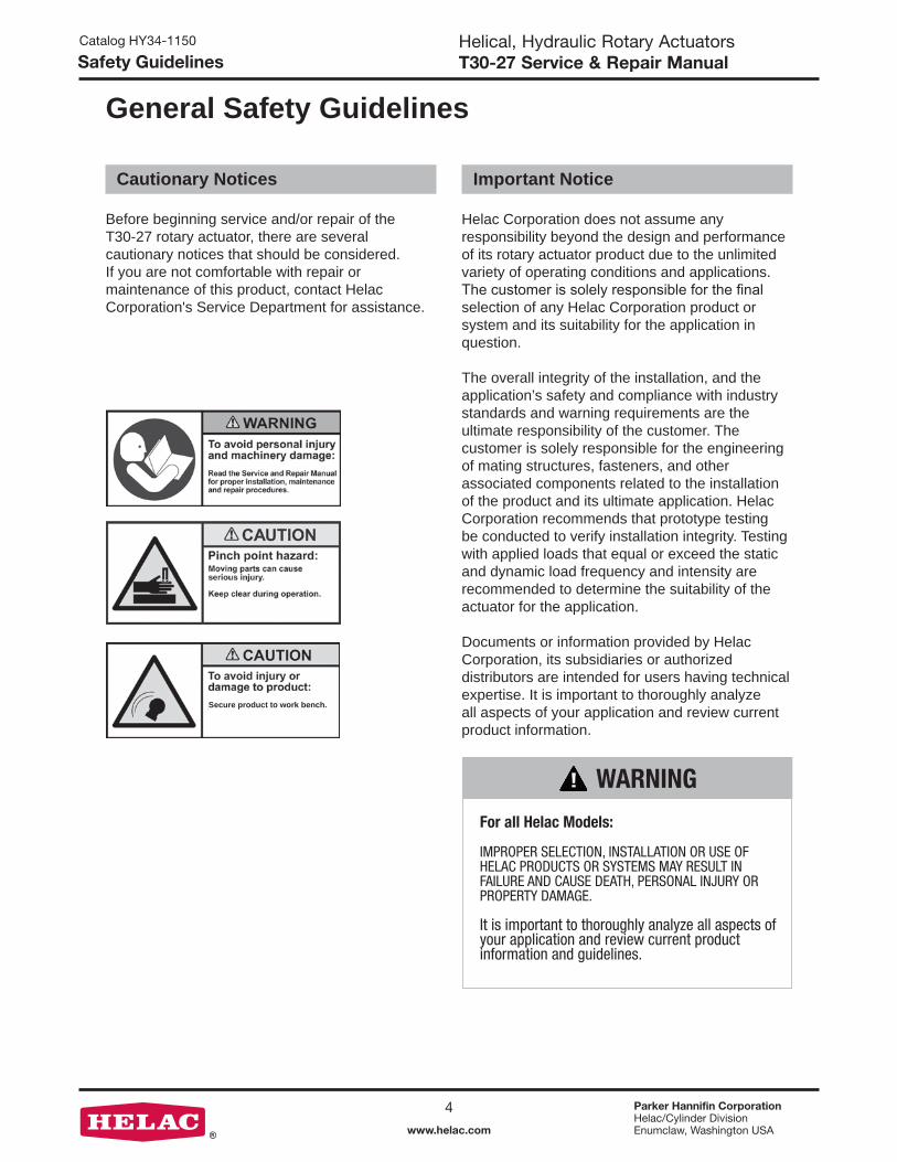
Before beginning service and/or repair of the T30-27 rotary actuator, there are several cautionary notices that should be considered. If you are not comfortable with repair or maintenance of this product, contact Helac Corporation's Service Department for assistance.
Cautionary Notices
Secure product to work bench.
Helac Corporation does not assume any responsibility beyond the design and performance of its rotary actuator product due to the unlimited variety of operating conditions and applications. The customer is solely responsible for the final selection of any Helac Corporation product or system and its suitability for the application in question.
The overall integrity of the installation, and the application’s safety and compliance with industry standards and warning requirements are the ultimate responsibility of the customer. The customer is solely responsible for the engineering of mating structures, fasteners, and other associated components related to the installation of the product and its ultimate application. Helac Corporation recommends that prototype testing be conducted to verify installation integrity. Testing with applied loads that equal or exceed the static and dynamic load frequency and intensity are recommended to determine the suitability of the actuator for the application.
Documents or information provided by Helac Corporation, its subsidiaries or authorized distributors are intended for users having technical expertise. It is important to thoroughly analyze all aspects of your application and review current product information.
Important Notice
WARNING
For all Helac Models: IMPROPER SELECTION, INSTALLATION OR USE OF HELAC PRODUCTS OR SYSTEMS MAY RESULT IN FAILURE AND CAUSE DEATH, PERSONAL INJURY OR PROPERTY DAMAGE.
It is important to thoroughly analyze all aspects of your application and review current product information and guidelines.
Safety Guidelines

5 Parker Hannifin CorporationHelac/Cylinder DivisionEnumclaw, Washington USAwww.helac.com
Helical, Hydraulic Rotary ActuatorsT30-27 Service & Repair Manual
Catalog HY34-1150
Product Identification
A unique serial number is located on each T30-27 rotary actuator. The serial number is stamped on the housing and can also be found on the Identification (ID) Tag. The serial number may be required before parts and/or service issues can be resolved. In some cases, it may be necessary to remove paint to expose the serial number.
Product Identification

6 Parker Hannifin CorporationHelac/Cylinder DivisionEnumclaw, Washington USAwww.helac.com
Helical, Hydraulic Rotary ActuatorsT30-27 Service & Repair Manual
Catalog HY34-1150
Maintenance
Daily
1. Apply a clean lithium or compatible grease to the grease fittings daily when operating the actuator in severe conditions such as abrasive dust or prolonged submersion in water. Apply grease until grease flows from the grease reliefs or shaft wiper seal.
2. Make sure the grease reliefs are functioning properly. Open or replace non-functioning grease reliefs immediately.
NOTICE Helac Corporation uses a lithium-based grease in assembly. A high quality grease compatible with lithium grease may be used.
Weekly
1. Apply a clean lithium or compatible grease to the grease fittings weekly when operating the actuator in non-severe environments and conditions.
Maintenance

7 Parker Hannifin CorporationHelac/Cylinder DivisionEnumclaw, Washington USAwww.helac.com
Helical, Hydraulic Rotary ActuatorsT30-27 Service & Repair Manual
Catalog HY34-1150
Troubleshooting Guide
* Replacement parts may be needed.
Problem Possible Cause SolutionShaft rotates slowly or not at all Insufficient torque output
Low rate of fluid flow
Counterbalance valve has internal leakage
Leak in piston and/or shaft seal
Corrosion build-up on the thrust surfaces
Swollen seals caused by incompatible hydraulic fluid
Air in actuator
Verify correct operating pressure. Do not exceed OEM’s pressure specifications. Load may be above maximum capacity of the actuator.
Inspect ports for obstructions and hydraulic lines for restrictions and leaks.
Disconnect hydraulic lines and bypass valve. Leave valve ports open and operate the actuator through housing ports (do not exceed OEM’s operating pressure). The valve must be replaced if a steady flow of fluid is seen coming from the valve ports.
Remove the port plugs and the housing’s valve ports. Operate the actuator through the housing ports. Conduct the internal leakage test as described in the Testing Section on Page 24.
Re-build the actuator. Remove all rust, clean thoroughly and then polish.*
Re-build the actuator with new seals. Use fluid that is compatible with seals and bearings. Contact Helac Corporation for more information.
Purge air from actuator. See bleeding procedures outlined on Page 25.
Operation is erratic or not responsive Air in actuator Purge air from actuator. See bleeding procedures outlined on Page 25.
Selected position cannot be maintained Counterbalance valve has internal leakage
Leak in piston and/or shaft seal
Air in actuator
Disconnect hydraulic lines and bypass valve. Leave valve ports open and operate the actuator through housing ports (do not exceed OEM’s operating pressure). The valve must be replaced if a steady flow of fluid is seen coming from the valve ports.
Remove the port plugs and the housing’s valve ports. Operate the actuator through the housing ports. Conduct the internal leakage test as described in the Testing Section on Page 24.
Purge air from actuator. See bleeding procedures outlined on Page 25.
Troubleshooting Guide

8 Parker Hannifin CorporationHelac/Cylinder DivisionEnumclaw, Washington USAwww.helac.com
Helical, Hydraulic Rotary ActuatorsT30-27 Service & Repair Manual
Catalog HY34-1150
T30-27 Assembly Drawing
Assembly Drawing

9 Parker Hannifin CorporationHelac/Cylinder DivisionEnumclaw, Washington USAwww.helac.com
Helical, Hydraulic Rotary ActuatorsT30-27 Service & Repair Manual
Catalog HY34-1150
T30-27 Exploded View
Exploded View

10 Parker Hannifin CorporationHelac/Cylinder DivisionEnumclaw, Washington USAwww.helac.com
Helical, Hydraulic Rotary ActuatorsT30-27 Service & Repair Manual
Catalog HY34-1150
Parts List — Actuator
SEALSSold as "kit" only
Item Description Quantity
200 ......... Cup Seal — Piston Sleeve .........................1 201 ......... Cup Seal — Piston Sleeve* ........................1 202 ......... Cup Seal — Piston Sleeve .........................1 203 ......... Cup Seal — Piston Sleeve* ........................1 205 ......... Cup Seal — Shaft ......................................2 206 ......... Wiper Seal .................................................2 208 ......... O-Ring Seal — Adapter ............................2 220 ......... O-Ring Seal — Housing ............................1 221 ......... B/U Ring — Housing ..................................1 230 ......... O-Ring Seal — Housing ............................1
BEARINGSSold as "kit" only
Item Description Quantity
302 ......... Bushing ......................................................2 304 ......... Thrust Washer ............................................2
*Energizer Removed
PARTSItem Description Quantity
01.1 ........ Housing (P1) ..............................................1 01.2 ........ Housing (P2) ..............................................1 02 ........... Shaft ...........................................................1 03 ........... Piston Sleeve .............................................1 05 ........... Bearing Retainer ........................................2 07............ Adapter .......................................................2 09............ Spacer ........................................................2
HARDWAREItem Description Quantity
102 ......... Screw .........................................................2 106.1 ...... Plug (SAE-6) ...............................................2 106.3 ...... Plug (SAE-4) ..............................................2 111 ......... Grease Fitting .............................................2
Spare PartsSpare parts must be ordered through the vehicle/machine OEM. Seals and wear guides are available as complete kits only! In order to obtain the correct parts, it is essential to provide the serial number for the actuator to be repaired. See Product Identification on Page 5. To identify spare parts required, refer to the Assembly Drawing, Exploded View Drawing and the Parts List.
Seal and Bearing kits can be ordered online at http://www.helac.com/store/
Parts List

11 Parker Hannifin CorporationHelac/Cylinder DivisionEnumclaw, Washington USAwww.helac.com
Helical, Hydraulic Rotary ActuatorsT30-27 Service & Repair Manual
Catalog HY34-1150
4.
2.
1.
3.
NOTICE All numbers that appear in parenthesis ( ) in the following sections refer to items on Page 8, 9 and10.
The T30-27 helical, hydraulic rotary actuator is comprised of the following major components:
1. Housing
2. Shaft
3. Piston Sleeve
4. Bearing Retainers
Secure product to work bench.
Spraying fluids:Contents under pressure. Wear approved eye protection.Use caution when removing port plugs and fittings.
CAUTION
1.
4.
Component Identification
Component Identification

12 Parker Hannifin CorporationHelac/Cylinder DivisionEnumclaw, Washington USAwww.helac.com
Helical, Hydraulic Rotary ActuatorsT30-27 Service & Repair Manual
Catalog HY34-1150
Housing Disassembly
Product Inspection
Ensure that the actuator is at end of stroke from Port P2.
1. Carefully remove the four plug fittings (106). Drain the hydraulic oil and inspect for contamination (i.e., dirt, water and metal).
2. Remove the grease fittings (111) from each end of the housing.
3. Firmly secure the P1 (01.1) end of the actuator housing to a work bench.
4. Insert 5/8-11 bolts or studs into mounting holes in P2 housing half feet.
Make sure the T30-27 is thoroughly cleaned prior to disassembly. Clean all machined parts in a wash tank and dry with compressed air. Be sure to inspect the actuator prior to disassembly.
Disassembly

13 Parker Hannifin CorporationHelac/Cylinder DivisionEnumclaw, Washington USAwww.helac.com
Helical, Hydraulic Rotary ActuatorsT30-27 Service & Repair Manual
Catalog HY34-1150
Housing Disassembly
5. Unscrew housing halves.
6. Gently remove P2 housing half (01.2)
Disassembly

14 Parker Hannifin CorporationHelac/Cylinder DivisionEnumclaw, Washington USAwww.helac.com
Helical, Hydraulic Rotary ActuatorsT30-27 Service & Repair Manual
Catalog HY34-1150
Shaft Removal
3. Gently remove shaft and piston sleeve assembly.
4. Mark timing between piston sleeve and shaft spline.
1. Use a strap wrench to begin rotating shaft and piston sleeve assembly out of P1 housing half using clockwise rotation.
2. Look inside the housing. Timing marks (center punches) will be visible on the ring gear inside the housing and the piston sleeve. Typically there should be two marks close together on the piston sleeve one for the inside and outside gear teeth. If no timing marks are located on any items, use a push type center punch to make new marks.
When the timing marks are located, use either a punch or a permanent marker (may wash off) to mark all the items. When doing reassembly, these marks will need to be lined up to achieve proper timing.
Timing Marks
Timing Marks
Disassembly

15 Parker Hannifin CorporationHelac/Cylinder DivisionEnumclaw, Washington USAwww.helac.com
Helical, Hydraulic Rotary ActuatorsT30-27 Service & Repair Manual
Catalog HY34-1150
Piston Sleeve Removal
1. Press bearing retainer (05) off of P2 end of shaft (02).
2. Remove piston sleeve (03) from shaft (02)
Disassembly

16 Parker Hannifin CorporationHelac/Cylinder DivisionEnumclaw, Washington USAwww.helac.com
Helical, Hydraulic Rotary ActuatorsT30-27 Service & Repair Manual
Catalog HY34-1150
Bushing & Thrust Washer Removal
3. Remove the bushing and thrust washer from the P2 housing half.
4. The bushing in the P1 housing half is accessible only through the inside of the housing. Using a chisel punch, carefully collapse the bushing enough to relieve the press fit. Care must be exercised to prevent damage to the housing.
5. Remove the bushing and thrust washer from the P1 housing half.
1. The thrust washer (304) is retained in the housing by the bushing (302) which is a press fit. Removal of the bushing is accomplished by collapsing it. Do not remove unless it needs to be replaced.
2. The bushing in the P2 housing half is accessible through the SAE-6 port opening. Using a punch, carefully collapse the bushing enough to relieve the press fit. Care must be exercised to prevent damage to the port threads.
Thrust WasherBushing
Disassembly

17 Parker Hannifin CorporationHelac/Cylinder DivisionEnumclaw, Washington USAwww.helac.com
Helical, Hydraulic Rotary ActuatorsT30-27 Service & Repair Manual
Catalog HY34-1150
Seal Removal
4. Remove piston sleeve I.D. cup seals (200, 201)
1. Remove wiper (206) and cup (205) seals from both housing halves.
2. Remove exclusion seal O-ring seals (220, 221, 230) from P1 housing half.
3. Remove piston sleeve O.D. cup seals (202, 203).
Making a Seal Tool
The seal tool is merely a customized standard flat head screwdriver.
1. Heat the flat end with a torch until it glows.
2. Secure the heated end of the screwdriver in a vise and bend the heated end to a slight radius.
3. Round off all sharp edges of the tip to a polished finish. The tool may be modified slightly to your own personal preference.
Disassembly

18 Parker Hannifin CorporationHelac/Cylinder DivisionEnumclaw, Washington USAwww.helac.com
Helical, Hydraulic Rotary ActuatorsT30-27 Service & Repair Manual
Catalog HY34-1150
Component Inspection
1. Prior to inspection, clean all parts in a wash tank and dry with compressed air.
2. Housing
Inspect the cylinder bore for wear and scratches. Local polishing can repair minor scratches and damage. Inspect all bearing and seal surfaces for signs of wear or damage. Check the condition of the gear teeth for any signs of extreme wear or chipping. Inspect the exterior of the housing for signs of damage or cracking. Inspect the threads for galling or cross threading. Make sure that the housing halves spin freely together. Evaluate the surface finish of the seal grooves.
3. Shaft
Check the shaft surface for scratches from the piston seal or other damages. Small or minor scratches can be carefully polished. Examine the condition of the gear teeth.
4. Piston Sleeve
Inspect the condition of the gear teeth. Evaluate the surface finish of the seal grooves.
5. Seals
Helac recommends replacement of all seals.
1. Locate the timing marks on the shaft (02), piston sleeve (03) and housing (01.1). Re-mark with a permanent marker or paint stick if needed.
Disassembly
Timing Mark Inspection

19 Parker Hannifin CorporationHelac/Cylinder DivisionEnumclaw, Washington USAwww.helac.com
Helical, Hydraulic Rotary ActuatorsT30-27 Service & Repair Manual
Catalog HY34-1150
Thrust Washer, Bushing and Seal Installation
Pre-Assembly
Dry Assembly
Assembly procedures require the P1 housing to be firmly secured to the work bench.
Thoroughly clean all components and lubricate all seals, bearings and contact surfaces with hydraulic oil prior to final installation.
1. Before installing seals, coat the seals and machined surfaces with clean hydraulic oil.
NOTICE
NOTICE
In some cases, for repair personnel not familiar with the actuator assembly process, it may be beneficial to perform a "dry" assembly. This will provide a better idea of how to properly align the gear teeth. A "dry" assembly is typically done without seals.
1. Install thrust washers (304), coated side up and drive bushings (302) into housing halves. Use care not to damage the bushings or housing halves.
Assembly

20 Parker Hannifin CorporationHelac/Cylinder DivisionEnumclaw, Washington USAwww.helac.com
Helical, Hydraulic Rotary ActuatorsT30-27 Service & Repair Manual
Catalog HY34-1150
Thrust Washer, Bushing and Seal Installation
2. Install wiper seals (206) into both housing halves.
3. Install O-Ring (230) then O-Ring (220) and B/U Ring (221) onto P1 (01.1) housing half.
5. Remove and discard the energizer (small O-Ring) from the inside of the piston sleeve O.D. cup seal (203) prior to installation. Also remove the energizer from inside of the piston sleeve I.D. cup seal (201).
O-Ring O-RingB/U Ring
Assembly

21 Parker Hannifin CorporationHelac/Cylinder DivisionEnumclaw, Washington USAwww.helac.com
Helical, Hydraulic Rotary ActuatorsT30-27 Service & Repair Manual
Catalog HY34-1150
Thrust Washer, Bushing and Seal Installation
6. Install the piston sleeve O.D. cup seal (202) onto the piston sleeve (03). (This seal should still have the energizer in it.)
7. Install the piston sleeve O.D. cup seal (203) onto the piston sleeve (03). Make sure to remove the energizer from the cup seal to prevent pressure trapping.
8. Remove and discard the energizer from the piston sleeve I.D. cup seal (201) prior to installation. Install the piston sleeve I.D. cup seals (200) and (201) inside the piston sleeve (03). (201) should be closest to the gearing.
Assembly

22 Parker Hannifin CorporationHelac/Cylinder DivisionEnumclaw, Washington USAwww.helac.com
Helical, Hydraulic Rotary ActuatorsT30-27 Service & Repair Manual
Catalog HY34-1150
Shaft and Piston Sleeve Installation
Shaft and Piston Sleeve Assembly
1. Before assembly of the shaft and piston sleeve, coat them with clean hydraulic oil.
2. Install piston sleeve (03) onto shaft (02) carefully aligning the timing marks on the shaft with the piston sleeve. Take care not to damage the piston seals with the shaft spines.
1. Before installing the shaft and piston sleeve assembly, coat with clean hydraulic oil.
2. Install shaft / sleeve assembly, carefully aligning the timing marks on the sleeve with the housing spline. Use strap wrench to rotate shaft into housing half, taking care to fully seat cup seal into housing half.
3. Press the bearing retainer (05) onto the P2 end of shaft.
4. Install cup seals (205) onto both ends of piston shaft assembly.
Assembly

23 Parker Hannifin CorporationHelac/Cylinder DivisionEnumclaw, Washington USAwww.helac.com
Helical, Hydraulic Rotary ActuatorsT30-27 Service & Repair Manual
Catalog HY34-1150
Housing Assembly
1. Re-assemble housing halves taking care to not damage housing O-rings or shaft cup seal.
2. Ensure O-Rings on port plug fittings (106.1 and 106.3) are in good condition. Install plug fittings.
3. Install grease fittings.
Assembly

24 Parker Hannifin CorporationHelac/Cylinder DivisionEnumclaw, Washington USAwww.helac.com
Helical, Hydraulic Rotary ActuatorsT30-27 Service & Repair Manual
Catalog HY34-1150
Testing the Actuator
Attach the actuator to either a hydraulic test bench or portable pump for greasing and testing. Make sure the actuator is secured to prevent movement.
1. Locate the grease fittings or ports on the actuator and using a grease gun, pack the seals with grease until it exhausts from the wiper seals.
2. Cycle the actuator slowly and re-grease as necessary. During testing, it is recommended that the actuator be cycled 20 to 30 times to remove air, check for leaks and the proper degrees of rotation.
Secure product to work bench.
Spraying fluids:Contents under pressure. Wear approved eye protection.Use caution when removing port plugs and fittings.
CAUTION
Testing and Greasing
Testing for Internal Leakage
1. Connect a 5,000 PSI test gauge into the hydraulic line to Port P1. Pressurize Port P1 until the shaft reaches the end of rotation.
NOTICE If the shaft is not completely bottomed out, hydraulic fluid will exhaust from Port P2 at a high velocity.
2. Remove and cap the hydraulic line to Port P2. Pressurize Port P1 to 2,500 PSI. Check for leakage at Port P2 and from around the main shaft and end cap seals. Leaks indicate improperly installed parts.
3. Reconnect the hydraulic line to Port P2 and pressurize P2 as in Step 1 above.
4. Check for leaks at Port P1 and around the main shaft and end cap seals as in Step 2 above.
Testing the Actuator

25 Parker Hannifin CorporationHelac/Cylinder DivisionEnumclaw, Washington USAwww.helac.com
Helical, Hydraulic Rotary ActuatorsT30-27 Service & Repair Manual
Catalog HY34-1150
Bleeding the Actuator
After installation of the actuator onto the equipment, it is important that all safety devices such as tie rods or safety cables be properly reattached. The actuator body is equipped with a pair of port plugs (106) which can be removed for bleeding.
For actuator without optional valve block installed.
Air should be purged through the upper ports P1 and P2. With that in mind, apply pressure hoses to the lower ports P1 and P2. See T30-27 Assembly Drawing on Page 8 and 9 for port location.
1. Connect a hydraulic line to upper port P1 routed either back to tank or to a minimum 5 gallon container to collect the purged oil.
2. Apply pressure to lower port P2 until actuator has fully rotated to one side.
3. With upper port P1 still venting to tank or 5 gallon container, apply pressure to the lower port P1 allowing oil/air to be purged from the open port.
4. Install upper port P1 plug and attach purge line to upper port P2.
5. Apply pressure to lower port P1 until actuator has fully rotated to the opposite side.
6. With upper port P2 still venting to tank or 5 gallon container, apply pressure to the lower port P2 allowing oil/air to be purged from the open port.
7. Install upper port P2 plug.
8. All air should be purged from the actuator.
Spraying fluids:Contents under pressure. Wear approved eye protection.Use caution when removing port plugs and fittings.
CAUTION
Bleeding the Actuator

26 Parker Hannifin CorporationHelac/Cylinder DivisionEnumclaw, Washington USAwww.helac.com
Helical, Hydraulic Rotary ActuatorsT30-27 Service & Repair Manual
Catalog HY34-1150
Warranty Information
Standard Warranty Information
Helac Corporation warrants its manufactured products to be free from defective material and factory workmanship. Helac Corporation shall replace or repair such products, which under normal use and service disclose such defects, and return the repaired or replacement products to the purchaser prepaid. Claims under this warranty will be satisfied only by repair or replacement of the unit or any defective part thereof. No cash payment or credit will be made for defective materials, workmanship, labor or incidental charges. Products under warranty shall be returned to Helac Corporation’s manufacturing facility at 225 Battersby Avenue, Enumclaw, Washington 98022 USA, transportation prepaid by the purchaser, for inspection by Helac Corporation, whose opinion as to defects shall be conclusive.
The warranty period shall be 12 months from the date of shipment from Helac Corporation’s manufacturing facility for Helac Corporation approved applications. This warranty shall be voided as to any products which have been repaired, worked upon, or altered by persons not authorized by Helac Corporation, or which have been subject to misuse, negligence, accident, or overload. In no event shall Helac Corporation be liable for any incidental or consequential damages.
Helac Corporation reserves the right to make changes in the design or construction of any of its products at any time without incurring any obligations to make changes or alterations to products previously sold.
This warranty is in lieu of all other and/or prior warranties, expressed or implied, and no other company or person is authorized to represent or assume for Helac Corporation any liability in connection with the sale of Helac Corporation products other than set forth herein.
Return and Debit Policy for Actuators
Unless agreed to in advance, all actuators will be shipped to Helac Corporation, freight prepaid within seven days after receipt of return authorization. Prior to any returns, a Return Material Authorization (RMA) form is to be requested from an authorized Helac Corporation representative. Upon receipt of the RMA form, the customer is to provide when applicable, the part number, serial number, failure date, description of problem and the customer claim or reference number. All shipments to Helac Corporation are to include the completed RMA form.
Upon receipt of the actuator(s) at the Helac Corporation facilities, an inspection will be performed and an authorized representative will provide a written quote. This quote will list the findings of the inspection and will state whether or not the warranty claim has been accepted. Actuators returned for credit may be subject to the Helac Corporation re-stocking fee.
If Helac Corporation does not receive a response to their quote within 30 calendar days, the actuator will be either scrapped or returned and an invoice for the debit amount, including the freight charges, will be sent to the claim originator.
Return and Debit Policy for Service Parts
Return of service parts, normally stocked by Helac Corporation, must be authorized in advance. This will include seal and bearing kits as well as any and all fabricated parts. Return of any special order parts will be authorized on a case-by-case basis. All returns are to be shipped to Helac Corporation freight prepaid within seven days after receipt of return authorization. Helac Corporation has a minimum re-stocking fee of 20 percent.
Prior to any returns, Return Material Authorization (RMA) form is to be requested from an authorized Helac Corporation representative. Upon receipt of the RMA form, the customer is to provide part number, receipt date, description of problem and the customer claim number. All shipments to Helac Corporation are to include the completed RMA form.
Warranty

27 Parker Hannifin CorporationHelac/Cylinder DivisionEnumclaw, Washington USAwww.helac.com
Helical, Hydraulic Rotary ActuatorsT30-27 Service & Repair Manual
Catalog HY34-1150
Notes

Parker Hannifin CorporationHelac/Cylinder Division225 Battersby AvenueEnumclaw, WA 98022 USAphone (360) 825-1601fax (360) 825-1603www.helac.com
11/17 / Catalog HY34-1150