heavy ion charge stripping at frib - hb2016 · pdf filea superconducting radio frequency...
TRANSCRIPT

This material is based upon work supported by the U.S. Department of Energy Office of Science under Cooperative Agreement DE-SC0000661, the State of Michigan and Michigan State University. Michigan State University designs and establishes FRIB as a DOE Office of Science National User Facility in support of the mission of the Office of Nuclear Physics.
F. Martia, P. Guetschowa, J. Gilla, A. Hershcovitchc, N. Josepha, M. LaVerea, Y. Momozakib, J. A. Nolena,b, C. B. Reedb,
and P. Thiebergerc
a Michigan State University, b Argonne National Laboratoryc Brookhaven National Laboratory
Heavy Ion Charge Stripping at FRIB

What is FRIB?Charge stripper options
• Comparison
Baseline Choice: Liquid lithium• Experimental work performed• Status of the design and fabrication
Alternate charge stripper: Helium gas Experimental work performed
Future work
Outline
F. Marti, July 2016 HB2016, Slide 2

What is FRIB?US-DOE SC and Michigan State University
F. Marti, July 2016 HB2016, Slide 3
The Facility for Rare Isotope Beams will produce secondary beams by the projectile fragmentation method at the production target. The fragments will be separated in flight providing fast development for all ions. The facility will provide fast (at the energy emerging from the target), stopped and reaccelerated beams.
Key features of the driver linac are 400 kW beam power for all ions and E/A> 200 MeV/u
A Superconducting Radio Frequency folded linac layout was chosen with two ECR ion sources located above the linac tunnel.
The stripper is located at the end of Linac Segment 1 (after the β = 0.041 and 0.085 cavities). where ions have energies between 16 and 20 MeV/u. The bend will select multiple charge states of the stripped beam (up to five charge states for uranium ions) for simultaneous acceleration in the rest of the linac.
Charge stripper

The expected energy deposition in the carbon foil stripper is of the order of 30 MW/cm3
The radiation damage at the FRIB fluence is very high
Why not a carbon foil stripper?
F. Marti, July 2016 HB2016, Slide 4
One of the main differences between heavy ion and proton accelerators is the much higher (~ four orders of magnitude) energy deposition per unit length of the heavy ions compared with the protons
Energy loss in carbon
H
Ca
U
Xe
The energy loss of the heavy ions in material is much higher than for protons. It is a challenge to dissipate the power.
In c
arbo
n
FRIB stripper energy

Solid carbon foils can be used only with low mass ions at low intensities• We need to utilize a stripping media that doesn’t suffer radiation damage to the
material lattice and can remove the heat quickly
Two options are available, flowing liquids and gases
For liquids, lithium is the best option. • It has a relatively low melting point (181 C), low vapor pressure at that temperature
(<10-7 Pa), high boiling point (1342 C), high heat capacity and low viscosity.• The negative aspect is that it is pyrophoric, safety concerns are important
For gases, helium is the best candidate.• The average charge state after stripping is higher than for heavier mass gases (like
N2 or Ar)• It is difficult to pump and expensive to replenish, we need to recover and recirculate.
Developed at RIKEN (H. Okuno, H. Imao and colleagues)• MSU and BNL developed a plasma window based system
Options considered
F. Marti, July 2016 HB2016, Slide 5

A larger energy spread is expected from the helium gas than from the liquid lithium film stripper
Energy spread in helium gas
F. Marti, July 2016 HB2016, Slide 6
Energy spread increase along a 30 cm gas cell at a pressure of 300 mbar neglecting density variation due to heating
105 ions starting at 238U34+ (16.5 MeV/u) Color bar shows the
logarithm of the density
x (cm)
Ener
gy S
prea
d (M
eV/u
)
P_300_mbar_L_30_N_100000_Estrag_1_
0 5 10 15 20 25 30
-0.15
-0.1
-0.05
0
0.05
0.1
0.15
0
0.5
1
1.5
2
2.5
3
3.5
4
4.5
The heating of the helium gas will change its density, varying the energy loss and increasing the emerging energy spread• To minimize the effect we plan on counter flow
sections of the stripper at high transverse velocity.

Advantages DisadvantagesLiquid lithium • Expected to provide higher
charge state• Has been tested with high
power beam deposition (stopping protons)
• Smaller energy spread than gas stripper
• Requires electromagnetic pump that needs to be tested
• High safety concern because of the fire hazard
• Requires mitigation of possible contamination of superconducting cavities
Helium gas • Less safety concerns than liquid lithium
• No contamination to superconducting cavities
• Expected lower charge state than liquid lithium
• Difficulty in containing helium, needs replenishing
• Higher energy spread than the lithium charge stripper
• No beam tests yet, need to develop counterflow
Comparison of the two options
F. Marti, July 2016 HB2016, Slide 7
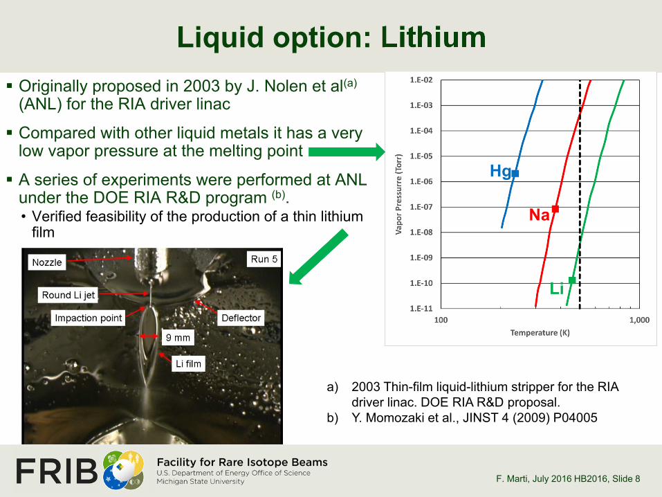
Liquid option: Lithium
F. Marti, July 2016 HB2016, Slide 8
Originally proposed in 2003 by J. Nolen et al(a)
(ANL) for the RIA driver linac
Compared with other liquid metals it has a very low vapor pressure at the melting point
A series of experiments were performed at ANL under the DOE RIA R&D program (b).• Verified feasibility of the production of a thin lithium
film
a) 2003 Thin-film liquid-lithium stripper for the RIA driver linac. DOE RIA R&D proposal.
b) Y. Momozaki et al., JINST 4 (2009) P04005
Hg
Na
Li

Stripper film produced by high velocity jet
F. Marti, July 2016 HB2016, Slide 9
The thin lithium film needs to move very fast (~ 50 m/s) to move the heat away from the impact point. This is achieved by producing a high pressure (~15 bars) lithium jet in a 0.5 mm diameter nozzle.The jet impinges on a flat deflector and produces the thin film.
Deflector
Lithium returns to pump
Stripped Beam
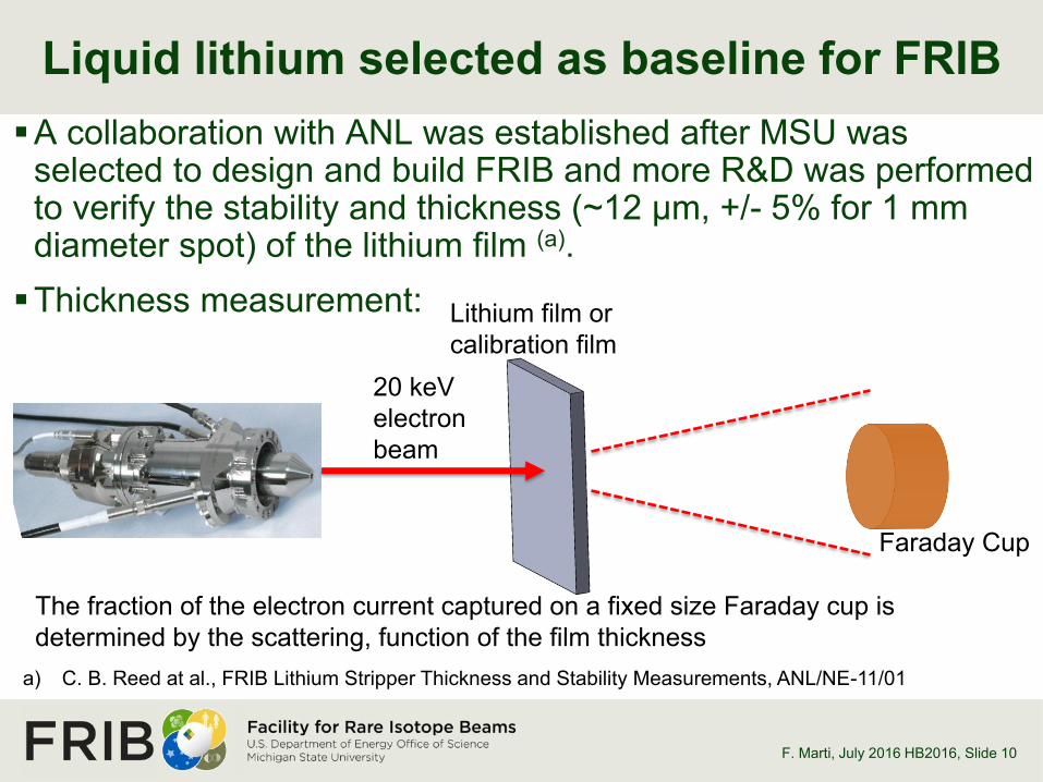
A collaboration with ANL was established after MSU was selected to design and build FRIB and more R&D was performed to verify the stability and thickness (~12 µm, +/- 5% for 1 mm diameter spot) of the lithium film (a).
Thickness measurement:
Liquid lithium selected as baseline for FRIB
F. Marti, July 2016 HB2016 , Slide 10
a) C. B. Reed at al., FRIB Lithium Stripper Thickness and Stability Measurements, ANL/NE-11/01
Lithium film or calibration film
Faraday Cup
The fraction of the electron current captured on a fixed size Faraday cup is determined by the scattering, function of the film thickness
20 keV electron beam

Can the thin film survive the power deposition? YES
F. Marti, July 2016 HB2016, Slide 11
The major question we needed to answer was related to the possibility that the power deposited on the film by the beam would produce evaporation and/or boiling and destroy the film in the processWe borrowed the LEDA (LANL) proton source and adapted it at MSU
with a new beam line to produce a proton beam of 3 mm diameter and power density comparable to the power deposited by the uranium beam at the FRIB stripper. The source was then moved to ANL.
Incoming proton beam
Lithium film, metallic reflection surface
Reflection of the incoming beam on the lithium surface

The proton beam (65 kV, 300 W) stopped completely in the lithium film.
Visualizing the flow of heated lithium
F. Marti, July 2016 HB2016, Slide 12
Energy loss of a 65 kV proton beam on lithium calculated with SRIM. The power is deposited on the first 1.5 um.
Still frames showing the trail of heated flow lines. By moving the impact point from left to right the flow lines can be visualized.

The highest power density split the film below the impact point, without disturbing the interaction volume. 30% of the maximum power deposition expected at FRIB (or 200% of
power density if deposition depth is included)
Achieved power densities comparable to FRIB
F. Marti, July 2016 HB2016, Slide 13
The LEDA proton beam coming from the right stops in the lithium film. Three different focusing settings are shown. The rightmost image shows film splitting but only appeared in some instances
Y. Momozaki et al., J. Radioanal. Nucl. Chem. DOI 10.1007/s10967-015-4074-9

The experiments performed at ANL used a single pass lithium system, allowing runs of ~20 minutes before recycling. Pressure determines the film thickness and velocity.
In other applications the liquid metals are moved by rotary electromagnetic pumps. These pumps are mostly used in high volume low pressure applications and do not provide the pressure stability needed by our stripper, the pressure determines the film thickness
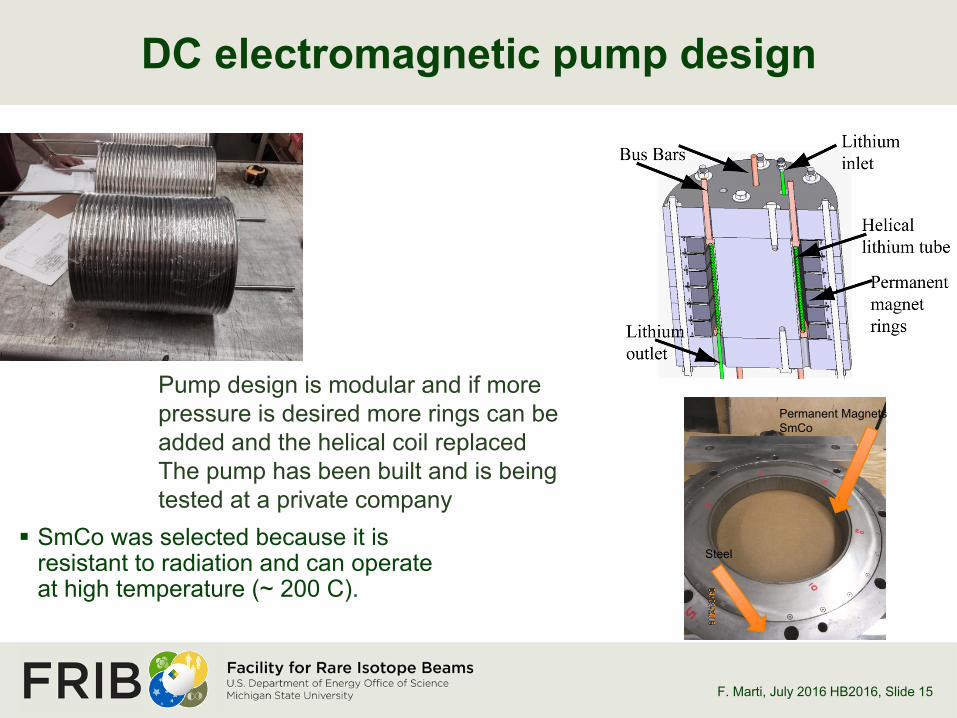
We have developed a DC permanent magnet pump where the lithium circulates in a helical tube with current moving parallel to the coil axis and a magnetic field perpendicular to the axis (pressure required ~ 15 bars). This is a high temperature version of a pump developed for Ga/In by R. Smither at ANL.
How do we pump the lithium to the required pressure?
F. Marti, July 2016 HB2016, Slide 14
DC electromagnetic pump design
F. Marti, July 2016 HB2016, Slide 15

DC electromagnetic pump design
F. Marti, July 2016 HB2016, Slide 15

DC electromagnetic pump design
F. Marti, July 2016 HB2016, Slide 15

DC electromagnetic pump design
F. Marti, July 2016 HB2016, Slide 15
Steel
Permanent MagnetsSmCo
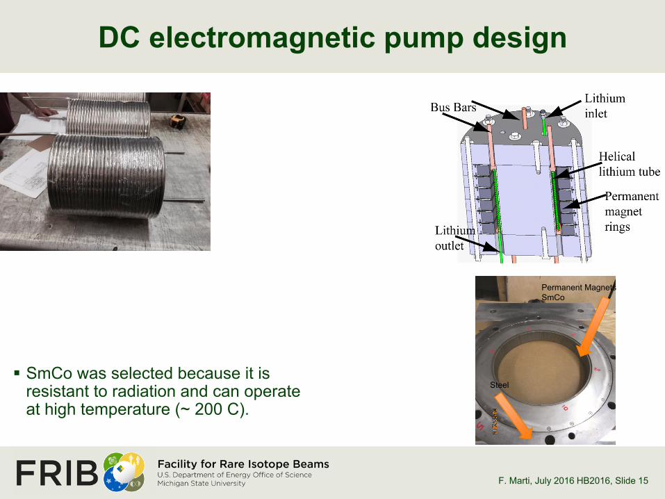
DC electromagnetic pump design
F. Marti, July 2016 HB2016, Slide 15
SmCo was selected because it is resistant to radiation and can operate at high temperature (~ 200 C).
Steel
Permanent MagnetsSmCo
DC electromagnetic pump design
F. Marti, July 2016 HB2016, Slide 15
SmCo was selected because it is resistant to radiation and can operate at high temperature (~ 200 C).
Steel
Permanent MagnetsSmCo
Pump design is modular and if more pressure is desired more rings can be added and the helical coil replacedThe pump has been built and is being tested at a private company

Charge stripper module design
F. Marti, July 2016 HB2016, Slide 16
Beam
2 m
Safety is a main concern. Primary chamber is contained in a secondary vessel continuously filled with inert argon gas.
Argon TankDC Pump

The film is positioned with respect to the beam
F. Marti, July 2016 HB2016, Slide 17
A set of motors move the table with the lithium vacuum chamber up and down, left and right with respect to the beam.
The film is moved with respect to the beam.
The beam remains on the beamline center while we move the lithium film
A concern is that wear of the nozzle may change the film formation in a time shorter than the maintenance period and the motion of the table allows for some compensation

Activation of the lithium (mostly 7Be), and the argon gas in the secondary containment vessel as well as in the argon storage tankCompatibility of lithium with standard materials is a serious concern.
For example no aluminum can be used, nor copper vacuum gaskets Liquid lithium catches fire when in contact with water or oxygen and
reacts with nitrogen If a loss of vacuum is detected on the main lithium chamber:
• We shut off the valves that connect the stripper to the rest of the beamline• The lithium pump is turned off• We initiate a sequenced controlled cooling of the system
The main chamber is enclosed in the secondary containment vessel that is continuously filled with argon just above atmosphere and in case of a fire it is exhausted through a scrubber
Hazards associated with the lithium stripper
F. Marti, July 2016 HB2016, Slide 18
The liquid lithium stripper module is being assembled and we expect to have most of it ready for commissioning by the end of 2016.We plan to install it in the tunnel after the initial commissioning period
• To simplify commissioning a carbon foil will be used. Only low intensity and low and medium mass ions will be used in commissioning.
In the testing period we plan to:• Optimize the nozzle design to obtain a “flatter” stripper film
» The beamline can accept a +/- 20 % variation of stripper thickness (energy spread)» The measurements at ANL showed that this was achieved
• Determine long term (days instead of hours) stability of the film• Study wear rates of nozzle, deflector, etc.• Determine maintenance required to minimize unexpected breakdowns
Future work
F. Marti, July 2016 HB2016, Slide 19

Helium gas charge stripperRIKEN development
F. Marti, July 2016 HB2016, Slide 20
The development of a helium gas stripper for high intensity heavy ions was started by H. Okuno(a) at RIKEN, Japan
It was experimentally verified that the average charge state emerging from a helium stripper was significantly higher than that from an argon or nitrogen gas cell(b) at the RIKEN and FRIB energies
The integrated gas thickness needed to reach equilibrium at RIKEN’s energies is lower than for FRIB beams. Even at their lower pressures a complex pumping system is needed to capture most of the gas that escapes from the stripper cell.
(a) H. Okuno et al., PRSTAB 14 (2011) 033503(b) H. Imao et al., PRSTAB 15 (2012) 123501

How to reduce the helium loss?
F. Marti, July 2016 HB2016, Slide 21
P. Thieberger(a) (BNL) proposed the use of plasma windows to reduce the conductance from the gas cell to the rest of the beamline in the FRIB stripper.
A. Hershcovitch (BNL) developed the original concept of the plasma window(b). It consist of a wall stabilized plasma that heats the gas trying to escape from the high pressure cell. The increased velocity of the gas achieves a choked flow condition and higher viscosity, limiting the mass flow.
(a) P. Thieberger, Stripper and Target Technology for High Power Heavy Ion Beams Workshop, East Lansing (2009)
(b) A. Hershcovitch, J. Appl. Phys. 79, 5283 (1995).
Cathode
Cooling plates
Low pressure
Gas cellhigh
pressure
Plasma
Anode
Beam

Results from R&D at BNL for a 6 mm aperture
F. Marti, July 2016 HB2016, Slide 22
A conductance reduction factor of 8 was achieved at 30 A
Results from an 8 hour test
Discharge power dissipated in each plate of the 6 mm aperture plasma window as measured by the cooling water temperature increase.

Test stand with plasma windows at MSU
F. Marti, July 2016 HB2016, Slide 23
Gas cellPlasma window
Helium
The goal is to improve the helium containment and improve the lifetime of the components.
Cathode lifetime is an issue due to erosion of the W electrodes.
The plasma has damaged some of the window plates, we need to improve the cooling.
A large pump (not shown) is recycling the gas toward a buffer tank and back into the gas cellA heat exchanger will remove the heat deposited by the beam in the gas
Pump Chamber

We would like to acknowledge the following collaborators that contributed to the work presented here: J. Specht (ANL), J. Sherman (retired LANL), I. Silverman (Soreq, Israel).H. Okuno and the RIKEN team FRIB team
Acknowledgements
F. Marti, July 2016 HB2016, Slide 24