heavy duty milling machine - precision matthews...oct 03, 2018 · model 932m milling machine...
TRANSCRIPT

Copyright June 2017 © Quality Machine Tools,
LLC
PM-932M 10-3-2018 v13.docx 1
Heavy duty milling machine 6-speed gear head
Powered table (X axis) Powered headstock (Z axis)
Quill DRO & depth stop Total weight 1000 lbs
Cast iron stand
Model PM-932M
No portion of this manual may be reproduced or distributed
without the written approval of Quality Machine Tools, LLC

Copyright June 2017 © Quality Machine Tools,
LLC
PM-932M 10-3-2018 v13.docx 2
This manual describes PM-932M machines as shipped from January 2016.
There may be detail differences between your specific machine and the
information given here (with little or no impact on functionality). Please email us if
you have questions about any aspect of the manual or your machine (see our website
www.precisionmatthews.com for support addresses). Your feedback is welcomed!
New installation?
After uncrating the mill, please pay attention to the following:
Read the installation instructions at the BACK of this manual.
Handling the mill is at least a two-man job.
Hand-crank the headstock down until the spindle nose is just clear of the
table. Remove the hand crank, and set it aside.
Lifting gear – sling, hoist or forklift – must be rated for at least 1500 lb.
Working location of the mill must allow:
1. Full left-right travel of the table
2. Access to the back of the column (Z axis leadscrew maintenance)
3. Headroom for the Z-axis motor
Power requirement is 220V, 60Hz, 1φ, 15A circuit protection (spindle motor
8.6A, full load).
Extension cord not recommended; if no alternative, use 12 AWG not longer
than 20 ft.
BEFORE connecting power be sure that:
1. The machine is on a firm footing.
2. The Z-axis (headstock) and X-axis (table) motors are safely situated, not
installed in their working locations. Don't let them dangle on the cables!
3. There are no clamps or locks on moving parts.
4. The gearbox contains oil – check the sight glass at right of the headstock.
5. The gear levers are set for the lowest speed: Hi-Lo to L, 2-3-1 to 1.
6. The gears are fully engaged – hand-rotate (jiggle) the spindle forward and
back while applying light pressure on each gear lever, listening for the click
as the gears engage.
This manual contains essential safety advice on the proper setup, operation, maintenance, and
service of the PM-932M milling machine. Failure to read, understand and follow the manual may
result in property damage or serious personal injury.
There are many alternative ways to install and use a mill. As the owner of the mill you are solely
responsible for its proper installation and safe use. Consider the material contained in this manual to
be advisory only. Precision Matthews cannot be held liable for injury or property damage during
installation, or from negligence, improper training, machine modifications or misuse.

Copyright June 2017 © Quality Machine Tools,
LLC
PM-932M 10-3-2018 v13.docx 3

Copyright June 2017 © Quality Machine Tools,
LLC
PM-932M 10-3-2018 v13.docx 4
PM-932M
Frequently asked questions ...
My mill doesn't run at all ...
220 Vac power connected?
Power lamp lit (top left)? Press the POWER push-button
E-Stop button pressed in? (pops out when twisted to the right)
Fuse good?
R8 collets won't go into the spindle ...
The collet locating screw might be in too far. Lock the quill, then remove the spindle end cap, right, using a
hammer and soft metal drift in the drilled cavities. Back the screw out just enough to clear the collet.

Copyright June 2017 © Quality Machine Tools,
LLC
PM-932M 10-3-2018 v13.docx 5
Section 1 INTRODUCTION
MODEL 932M Milling Machine features and specifications
General information
The 932M is a robust "square column" mill designed for day-in, day-out use in the busy model shop. With an all-
up weight of 1000 lbs it can handle far more than the typical small machine, including end mills up to 1-1/4" and
face mills up to 3". For precise control of cutter depth there is a worm-driven quill downfeed with graduated dial
and DRO, completely independent of headstock up/down position.
The reversible spindle runs in high-quality (ISO355) tapered-roller bearings enclosed in a 3" diameter quill with
coarse and fine downfeed options. An oil-filled gearbox provides 6 spindle speeds from 90 to 1970 rpm.
Features of the headstock include choice of manual or powered elevation on dovetailed ways, 90o – 0
o – 90
o tilt,
and a quill depth stop for drilling operations. The 31.5" x 9.5" table is powered in the X axis by a variable-speed
dc motor. Table movement in both X and Y axes is along scraped dovetailed ways.
Supplied accessories
R8 drill chuck arbor and 1/2" (13mm) keyed chuck
22-24mm open-end wrench
R8 shell mill keyed arbor, 1" diameter, M10 threaded hole
Floor plan
These are minimum space requirements for full motion of the table.

Copyright June 2017 © Quality Machine Tools,
LLC
PM-932M 10-3-2018 v13.docx 6
T-slot dimensions
Dimensions
Weight, including cast iron stand 990 lb
Size W 49-1/2" x D 34-1/2" x H 75-1/4"
Stand footprint Approx. W 18-1/2" x D 27"
Electrical
Power requirement 220V, 60Hz, 1φ, 15A breaker
Full load current 8.6A, spindle motor only
Power cord 14 AWG x 6 ft
Motors
Main (spindle) Cap-start induction, 1.5 HP, 1725 rpm
X-axis (table traverse) DC gear motor, 1A
Z-axis gear motor (elevation) Cap-start induction, 120W
Headstock
Vertical travel (Z-axis) 13.5 in.
Left-right tilt 90o – 0
o – 90
o
Spindle
Speeds (rpm) 90, 210, 345, 670, 1180, 1970
Internal taper R8
Top end 6 splines, 28 mm OD
Quill travel 5 in.
Spindle to table 18 in. max
Spindle centerline to column face 10 in.
Drawbar 7/16 x 20, 18 mm wrench
Table
Size W 31.5 in. x D 9.5 in. x H 1.6 in.
Surface height Approx. 35" from floor
Maximum load 220 lb
Leadscrews Acme, inch pitch, 10 tpi
Front-back travel (Y-axis) 7.9 in.
Traverse (X-axis) 19.5 in.
T-slots (3) 14 mm wide, 80 mm centers

Copyright June 2017 © Quality Machine Tools,
LLC
PM-932M 10-3-2018 v13.docx 7
No list of precautions can cover every-thing. You cannot be too careful!
Everyday precautions This machine is designed for milling and drilling operations by experienced
users familiar with metal-working hazards.
Untrained or unsupervised operators risk serious injury.
Wear ANSI-approved full-face or eye protection at all times when using the
machine (everyday eyeglasses are not reliable protection against flying
particles).
Wear proper apparel and non-slip footwear – be sure to prevent hair, clothing or
jewelry from becoming entangled in moving parts. Gloves – including tight-fitting
disposables – can be hazardous!
Be sure the work area is properly lit.
Never leave chuck keys, wrenches or other loose tools on the machine.
Be sure the workpiece and machine ways are secure before commencing milling
or drilling – hold-downs and/or vise fully tightened, X-Y-Z axes locked, cutting
tool secured.
Use moderation: light cuts, low spindle speeds, slow table motion give better,
safer results than "hogging".
Don't try to stop a moving spindle by hand – allow it to stop on its own.
Disconnect 220V power from the mill before making adjustments, changing
tooling, or servicing. For routine mechanical work, only, disconnect by pressing
the RED power button on the control panel. Before opening the control panel,
disconnect by unplugging the power cord from the 220V outlet.
Maintain the machine with care – check lubrication and adjustments daily before
use.
Clean the machine routinely – remove chips by brush or vacuum, not
compressed air (which can force debris into the ways).

Copyright June 2017 © Quality Machine Tools,
LLC
PM-932M 10-3-2018 v13.docx 8
Section 2 USING THE MILL
FRONT PANEL CONTROLS
Connect the mill to a 220Vac source.
Press the green Power button to energize the main
contactor in the control box. The power lamp, top
left, should light, indicating that power is available to
all motors.
Press the O button to disconnect power from the
three motors.
The E-stop button, bottom left, has the same effect
as the O button, but it should be used only for its
intended purpose – emergency disconnect. The E-
stop button is not momentary; once in, it stays in
until twisted clockwise.
The Up and Down buttons control the Z-axis motor
(head elevation).
The main motor (spindle drive) is controlled by the
rotary switch at bottom right. F = Forward, S =
Stop, and R = Reverse.
SPINDLE SPEEDS
This is a gear-head machine with a constant speed motor and a two-stage gearbox providing a choice of six
spindle speeds. The first stage (H-L) selects the speed range, high or low, and the second stage (2-3-1) selects
a specific speed within that range.
Before switching on the spindle motor, be sure that both stages are properly engaged. Hand-rotate
(jiggle) the spindle forward and back while applying light pressure on each shift lever, listening for the click as
the gears engage.
Allow the spindle to stop completely before shifting gears
Spindle speeds (rpm)
L-1 90
L-2 210
L-3 345
H-1 670
H-2 1180
H-3 1970
Excessive cutter noise, chatter, poor finish and tool wear are often the result of too high a
feed rate, and/or too high a spindle speed. If unsure, go slow!
Figure 2-1 Electrical controls and gear levers

Copyright June 2017 © Quality Machine Tools,
LLC
PM-932M 10-3-2018 v13.docx 9
INSTALLING AND REMOVING TOOLING
The spindle and drawbar are designed for R-8 taper collets,
drill chucks and other arbors with the standard 7/16"-20
internal thread. The drawbar is threaded into the R-8 device
by a few turns of the upper nut, which is solidly pinned to the
bar. With sufficient length of the thread engaged, run the
lower nut down as far as it will go, then tighten it using two
wrenches, 17 mm upper, 19 mm lower (or 11/16" and 3/4").
To keep the spindle from turning too freely in this procedure,
select a low speed such as L-1. Another way of tightening
the lower nut is to hold the spindle using a 6-spline wrench,
nominal size 28 mm.
Replace the drawbar cap to protect bearings
and spline.
To remove the R-8 device, loosen the lower nut one half turn
or less, then tap the top of the drawbar with a brass or
dead-blow hammer to unseat the taper. Unscrew the
drawbar by turning the upper nut with one hand while
supporting the R-8 device with the other hand. Why?
Because tables, vises and workpieces can be damaged by
falling tools and drill chucks.
MOVING THE TABLE
Conventionally, left-right movement of the table is
said to be along the X-axis (also called "longitudinal
travel" or "traversing"). Front-back movement is on
the Y-axis, sometimes called "cross travel".
Each axis has a leadscrew with handwheel and
graduated dial with 0.001" divisions, Figure 2-3. If the
mill is not equipped with digital readouts (DROs), the
table can be accurately positioned by counting whole
turns and divisions, bearing in mind leadscrew
backlash. This means that table motion must always
be in the same direction up to the point of reference,
then on to the desired location. For example:
A hole is to be drilled 0.25" on the Y-axis relative to
the front edge of a workpiece in a vise, or otherwise
clamped to the table.
Figure 2-2 Spindle and drawbar
Both nuts on the drawbar are 19 mm or 3/4". The spindle can
be held using a 28 mm spline wrench (not supplied). The
gearbox is vented through the metal elbow, right, and clear
plastic tube.
Figure 2-3 Y-axis handwheel, X-axis locks & limit switch
In the limit switch assembly, arrowed, there are separate
microswitches, left and right , actuated by adjustable spring-
cushioned stop blocks (3).

Copyright June 2017 © Quality Machine Tools,
LLC
PM-932M 10-3-2018 v13.docx 10
Figure 2-4 Y-axis locks
Figure 2-5 X-axis power feed
1. Install an edge-finder in collet or chuck (a tip diameter of 0.2" is assumed).
2. Lock the X-axis by tightening both leaf-screws, Figure 2-3 (1).
3. If the reference edge is to the back the spindle centerline, do nothing; if not, rotate the Y-axis handwheel
clockwise to send the workpiece backwards (toward the column).
4. With the spindle running, lower the quill as necessary, then bring the table forward (counter-clockwise),
stopping at the point where the edge-finder just makes contact. Stop the spindle.
5. Loosen the thumbscrew on the Y-axis dial, Figure 2-3 (2), zero the dial, then re-tighten the screw.
6. Raise the quill, then rotate the handwheel one exact full turn counter-clockwise (0.1") to bring the reference
edge to the spindle centerline.
7. Rotate the handwheel 2-1/2 turns counter-clockwise to bring 50 on the dial opposite the datum; the spindle is
now exactly 0.25" to the back of the reference edge.
Be sure to loosen the X-axis lock screws before
moving the table, especially under power
X-AXIS POWER FEED
Power lamp The power lamp, a small LED on the right-facing surface, lights when the Power switch is on. Direction lever
Before setting the lever to L or R, make sure the X-axis locks are FREE, and the speed control is fully COUNTER CLOCKWISE
Press the Rapid Traverse button (momentary type) to drive the table rapidly in the direction set by the L-R lever. Reset button If the power feed unit draws more than 3.5 amps for more than 10 seconds, the overload switch will cut power and the reset button will pop out.
Press the O button on the main control box to
Copyright June 2017 © Quality Machine Tools,
LLC
PM-932M 10-3-2018 v13.docx 11
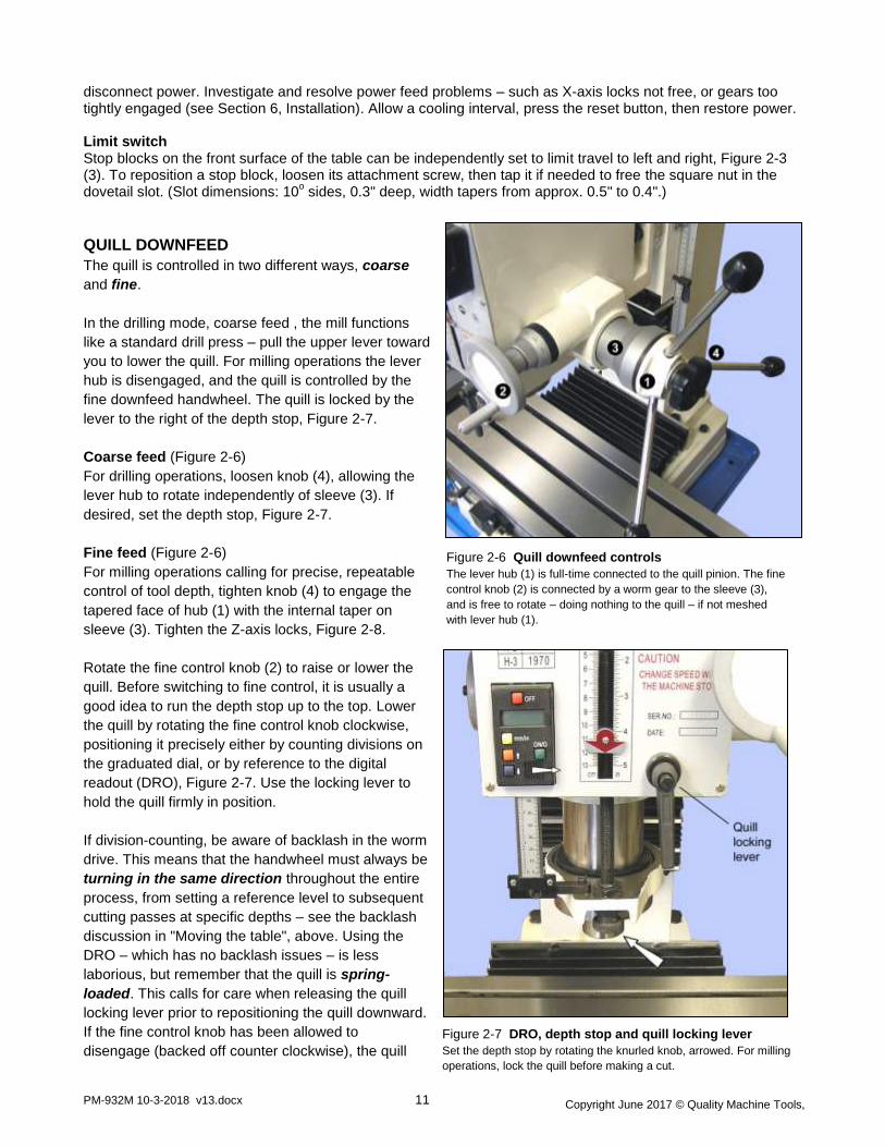
Figure 2-6 Quill downfeed controls
The lever hub (1) is full-time connected to the quill pinion. The fine
control knob (2) is connected by a worm gear to the sleeve (3),
and is free to rotate – doing nothing to the quill – if not meshed
with lever hub (1).
Figure 2-7 DRO, depth stop and quill locking lever
Set the depth stop by rotating the knurled knob, arrowed. For milling
operations, lock the quill before making a cut.
disconnect power. Investigate and resolve power feed problems – such as X-axis locks not free, or gears too tightly engaged (see Section 6, Installation). Allow a cooling interval, press the reset button, then restore power. Limit switch Stop blocks on the front surface of the table can be independently set to limit travel to left and right, Figure 2-3 (3). To reposition a stop block, loosen its attachment screw, then tap it if needed to free the square nut in the dovetail slot. (Slot dimensions: 10
o sides, 0.3" deep, width tapers from approx. 0.5" to 0.4".)
QUILL DOWNFEED
The quill is controlled in two different ways, coarse
and fine.
In the drilling mode, coarse feed , the mill functions
like a standard drill press – pull the upper lever toward
you to lower the quill. For milling operations the lever
hub is disengaged, and the quill is controlled by the
fine downfeed handwheel. The quill is locked by the
lever to the right of the depth stop, Figure 2-7.
Coarse feed (Figure 2-6)
For drilling operations, loosen knob (4), allowing the
lever hub to rotate independently of sleeve (3). If
desired, set the depth stop, Figure 2-7.
Fine feed (Figure 2-6)
For milling operations calling for precise, repeatable
control of tool depth, tighten knob (4) to engage the
tapered face of hub (1) with the internal taper on
sleeve (3). Tighten the Z-axis locks, Figure 2-8.
Rotate the fine control knob (2) to raise or lower the
quill. Before switching to fine control, it is usually a
good idea to run the depth stop up to the top. Lower
the quill by rotating the fine control knob clockwise,
positioning it precisely either by counting divisions on
the graduated dial, or by reference to the digital
readout (DRO), Figure 2-7. Use the locking lever to
hold the quill firmly in position.
If division-counting, be aware of backlash in the worm
drive. This means that the handwheel must always be
turning in the same direction throughout the entire
process, from setting a reference level to subsequent
cutting passes at specific depths – see the backlash
discussion in "Moving the table", above. Using the
DRO – which has no backlash issues – is less
laborious, but remember that the quill is spring-
loaded. This calls for care when releasing the quill
locking lever prior to repositioning the quill downward.
If the fine control knob has been allowed to
disengage (backed off counter clockwise), the quill

Copyright June 2017 © Quality Machine Tools,
LLC
PM-932M 10-3-2018 v13.docx 12
will jump up by 0.01" or more. To avoid this, make sure the fine control is firmly clockwise, lightly loading the
quill rack, before releasing the locking lever.
DRO
The DRO is in metric mode when switched on. Press the mm/in button to display inches. By pressing and
holding the Up arrow (incrementing) or Down arrow (decrementing) the display can be set to a chosen value.
The longer the buttons are held down, the faster the change in displayed value. Zero the display at any time by
pressing the ON/O button.
Switch off the DRO when not in use!
Replace the battery by sliding the cover (small arrow) to the right. For longer battery life use a 1.5V silver oxide
battery, SR44 or equivalent.
HEADSTOCK ELEVATION (Z-AXIS)
See page 7 for the Z-axis motor controls. Use the scale right of the headstock for rough positioning, Figure 2-8.
Be sure to loosen the Z-axis lock screws before moving the headstock.
Remove the crank handle before moving the headstock under power.
Hand crank
Use the hand crank, Figure 2-9, only for occasional small adjustments, then remove it and set it aside.
Figure 2-8
Z-axis scale and locking screws
Figure 2-9
Hand crank

Copyright June 2017 © Quality Machine Tools,
LLC
PM-932M 10-3-2018 v13.docx 13
Figure 2-10 Headstock tilted 45o counter clockwise
THREADING OPERATIONS
When threading a drilled hole it is essential to align the threading tap properly in the bore. The mill is often used
for this purpose, ideally with a dedicated (non-slip) tap holder or, for production work, an auto-reverse tapping
attachment. The drill chuck can be used instead for sizes up to (say) M6 or 1/4", beyond which the chuck may
not grip tightly enough to avoid slippage. Tapping can be done under power, or by hand turning the chuck (see
below). For either method, it is essential to use a tapping fluid. Any cutting oil is better than none, but most
users find Castrol's Moly Dee the most reliable for threading.
If power tapping bear in mind that reversing is not instantaneous, so be careful tapping blind holes. Be sure the
quill locking lever is free, and start trial work with the lowest spindle speed, L-1.
Turning the spindle by hand
One way to reduce the risk of small-tap breakage is to drill the workpiece, then remove the drill from the chuck
and replace it with the tap. Lower the quill to engage the tap, at the same time turning the chuck by hand while
maintaining light pressure on the quill. After a few turns of the chuck to establish alignment of the tap, there are
two options:
1. Unscrew the tap by reversing the spindle at the lowest speed, then remove the tap and complete the
tapping operation away from the mill.
2. Leave the tap in place, then loosen the chuck. Raise the quill, then use a hand tap holder to complete the
job with the workpiece remaining in the machine vise.
Turning the spindle by hand is easier if you select H-3, but revert to L-1 if backing out under power.
TILTING THE HEADSTOCK
In routine operations the user relies on squareness of
the spindle relative to both axes of the table. Front-to-
back squareness set at the factory, and is not
adjustable (by everyday methods), but in the other
plane the headstock can be set to any angle up to 90o
either side of the normal vertical position. [Because re-
establishing true vertical (tramming) on any mill is a
time consuming process, most machinists look first for
other ways of handling the project instead of tilting the
head.]
The headstock is secured by three nuts spaced 120o
apart, one underneath and one either side, Figure 2-
11. The headstock is top-heavy, and may swing
suddenly to either side unless a helper is on hand to
restrain it. Using a 24 mm wrench, testing for
moveability as you go, carefully loosen the nuts by
degrees. Be especially careful if the head has not
been moved before – the paint seal may let go without warning. (First-time tilting may also call for unusual effort
on the wrench.)
Copyright June 2017 © Quality Machine Tools,
LLC
PM-932M 10-3-2018 v13.docx 14
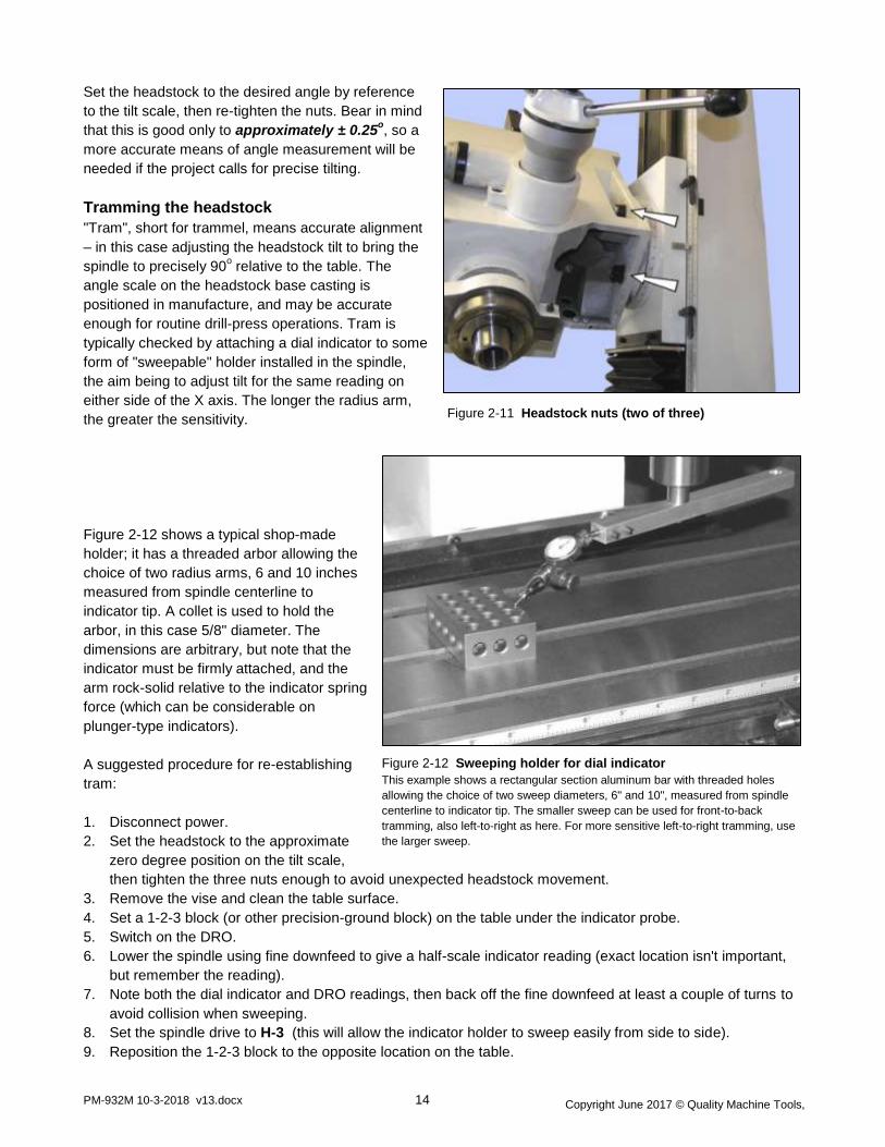
Figure 2-11 Headstock nuts (two of three)
Figure 2-12 Sweeping holder for dial indicator
This example shows a rectangular section aluminum bar with threaded holes
allowing the choice of two sweep diameters, 6" and 10", measured from spindle
centerline to indicator tip. The smaller sweep can be used for front-to-back
tramming, also left-to-right as here. For more sensitive left-to-right tramming, use
the larger sweep.
Set the headstock to the desired angle by reference
to the tilt scale, then re-tighten the nuts. Bear in mind
that this is good only to approximately ± 0.25o, so a
more accurate means of angle measurement will be
needed if the project calls for precise tilting.
Tramming the headstock
"Tram", short for trammel, means accurate alignment
– in this case adjusting the headstock tilt to bring the
spindle to precisely 90o relative to the table. The
angle scale on the headstock base casting is
positioned in manufacture, and may be accurate
enough for routine drill-press operations. Tram is
typically checked by attaching a dial indicator to some
form of "sweepable" holder installed in the spindle,
the aim being to adjust tilt for the same reading on
either side of the X axis. The longer the radius arm,
the greater the sensitivity.
Figure 2-12 shows a typical shop-made
holder; it has a threaded arbor allowing the
choice of two radius arms, 6 and 10 inches
measured from spindle centerline to
indicator tip. A collet is used to hold the
arbor, in this case 5/8" diameter. The
dimensions are arbitrary, but note that the
indicator must be firmly attached, and the
arm rock-solid relative to the indicator spring
force (which can be considerable on
plunger-type indicators).
A suggested procedure for re-establishing
tram:
1. Disconnect power.
2. Set the headstock to the approximate
zero degree position on the tilt scale,
then tighten the three nuts enough to avoid unexpected headstock movement.
3. Remove the vise and clean the table surface.
4. Set a 1-2-3 block (or other precision-ground block) on the table under the indicator probe.
5. Switch on the DRO.
6. Lower the spindle using fine downfeed to give a half-scale indicator reading (exact location isn't important,
but remember the reading).
7. Note both the dial indicator and DRO readings, then back off the fine downfeed at least a couple of turns to
avoid collision when sweeping.
8. Set the spindle drive to H-3 (this will allow the indicator holder to sweep easily from side to side).
9. Reposition the 1-2-3 block to the opposite location on the table.

Copyright June 2017 © Quality Machine Tools,
LLC
PM-932M 10-3-2018 v13.docx 15
Figure 2-13 Setup for indicating the vise
The tip of a standard dial indicator, arrowed, rides along the side
face of a ground reference bar
10. Swing the indicator holder to the new location, then lower the spindle – fine downfeed again – to give the
same dial indicator reading as in step (7).
If the headstock is perfectly trammed – highly unlikely at the first shot – the DRO reading should be as in step
(7). If not, loosen the nuts just enough to allow the headstock to be tapped a fraction of a degree in the direction
called for, then re-tighten the nuts. (The "tap" can be anything from a gentle hand-slap to a rap with a soft-face
dead-blow mallet).
Repeat steps (4) through (10) until satisfied with the tram, tightening the nuts as you go. This will likely call for
several iterations. There is no "right" tram; the acceptable difference in side-to-side readings depends on project
specs. As a starting point, aim for ± 0.001" on a radius of 5 or 6 inches.
A similar procedure may be used to check tram in the Y-axis, front to back. The difference here is that there is
that Y-axis tram is established in manufacture, and can be adjusted only by shimming the column-to-base
interface. This is a two-person procedure, requiring an engine hoist or some other means of un-weighting the
headstock (see Section 6, Installation).
INDICATING A VISE
A typical setup for indicating is shown in Figure 2-13.
Make sure that the spindle does not rotate
throughout the procedure. There is no spindle lock, but
you can set the gears for the lowest spindle speed (L-
1), then apply light spring pressure if necessary to the
splined upper portion of the spindle (not shown). With
the vise aligned by eye, tighten one of the clamp nuts
with very light pressure, then fully tighten the other one
to the point where the vise won't budge without a
definite tap from a dead-blow mallet. Set the indicator
tip against the upper edge of a precision reference bar
held in the vise (if not available, use the front face of
the fixed jaw of the vise instead – check for dings,
hone if necessary). Adjust, the Y-axis to pre-load the
indicator to mid range (say). Lock the Y-axis.
Note the reading at the tightly clamped end of the
bar, then traverse slowly to the looser end, tapping
in the vise as you go. Repeat the process as often as necessary for the desired accuracy, progressively
tightening the looser nut. Then fully tighten both nuts, and re-check, because tightening a nut can itself introduce
significant error. An established routine like this – tight to loose – can save a lot of time.
Ideally, the indicator reading should be identical at both ends of the reference bar. There is no "right" deviation;
what is acceptable depends on the project.
Vise keys
If your projects call for frequent removal and replacement of the vise, consider installing precision keys that fit
snugly in the mill's 14 mm slots, and in the corresponding slots in the base of the vise. The objective is a setup
that allows the vise to be removed and replaced routinely, yet be accurate enough for general machining without
the need for indicating every time.

Copyright June 2017 © Quality Machine Tools,
LLC
PM-932M 10-3-2018 v13.docx 16
Figure 2-14 Vise keys installed on X-axis
Keys can also be installed on the long axis.
Figure 2-15 Key for different size slots
Figure 2-16 Shimming the fixed jaw
Do this to correct misalignment between the vise keyways and the
jaw.
Vise keys are not commercially available, but are
easily made in the shop from any hardenable steel. If
your vise has 14 mm slots, make rectangular-shape
keys as Figure 2-14. If the vise has 16 mm, or other
width slots, make T-shape keys as Figure 2-15. Make
the keys very slightly oversize so that, when
hardened, it takes only a few strokes with a fine
stone or diamond hone to ease the fit. The objective is
a tight fit, but not so tight it takes more than
reasonable effort to lift the vise clear of the table.
There is no guarantee that a keyed vise will indicate
satisfactorily; "perfect indication" is possible only if the
slots in the base of the vise are truly parallel to the
fixed jaw. If this is not the case, consider adjusting
the fixed jaw by shimming, as Figure 2-16.

Copyright June 2017 © Quality Machine Tools,
LLC
PM-932M 10-3-2018 v13.docx 17
Figure 3-1 Gearbox drain plug
Section 3 MAINTENANCE
Lubrication
Oils are classified according to their viscosity. There are several viscosity indexes, the main ones being ISO
(International Standards Organization) and SAE (Society of Automotive Engineers). SAE adds another
complication with different indexes for engine and gear oils, further sub-divided into lists with and without the
suffix W, meaning "multigrade". Mistaking SAE engine oil for gear oil can be an issue; for instance, SAE 20
engine oil has about the same viscosity as SAE 80 gear oil, both roughly equivalent to just one number on the
ISO scale, ISO 68.
Recommended lubricants
Gearbox: ISO 68, such as SAE 80W90 auto gear oil, or Mobil DTE Heavy/Medium circulating oil (about 3 qts.)
Ball oilers (X and Y leadscrews): ISO 32 oil, such as 3-IN-ONE (the "motor oil" version of this brand is heavier,
about ISO 68, but it can also be used)
X, Y and Z axis ways (dovetails): ISO 68 oil, such as Mobil Vactra No. 2, or equivalent
Power feed (visible gears), quill rack and pinion, Z-axis helical gears: light general purpose grease, NLGI No. 2,
or equivalent
X and Y leadscrews: ISO 68 oil, such as Vactra No. 2 or 3-IN-ONE Motor Oil
Z leadscrew: ISO 68 oil or NLGI No. 2 grease
General
Assuming a clean environment – free from abrasive particles and machining debris – lack of proper lubrication is
the main cause of premature wear. Rotating parts are easy to lubricate, sliding parts are not. Gibs are tightened
for the best compromise between rigidity and slideability, which means practically zero gap between the ways.
Take time to understand exactly which are the bearing surfaces on the various dovetail surfaces; this is not
obvious – some of the interfaces look like bearing surfaces, but are simply narrow gaps.
Apply the recommended way-oil with a dedicated short-bristle brush such as the type used for applying flux. Use
a similar brush to apply oil or grease to the leadscrews.
Remove all machining debris and foreign objects before lubricating ANYTHING! If need be,
any oil is better than no oil – but use the recommended lubricants when you can.
Gearbox drain and refill
1. Run the mill a few minutes to warm the oil if necessary.
2. Remove the sheet metal cover from the underside of the
headstock (four 5 mm screws).
3. Place a 1-gallon or larger drain pan under the headstock.
4. Using a 6 mm hex wrench remove the drain plug, Figure 3-1.
5. Allow the oil to drain completely, then replace the drain plug.
6. Remove the fill plug, Figure 3-2, then add just a few ounces
of oil.
7. When satisfied that the headstock is oil-tight, add oil to the
halfway mark on the sight glass (about 3 qts total).
8. Replace the fill plug.
9. Replace the sheet metal cover, unless going on to service
the quill rack and pinion, below.
Unplug the 220V power cord before
any maintenance operation!

Copyright June 2017 © Quality Machine Tools,
LLC
PM-932M 10-3-2018 v13.docx 18
Figure 3-2 Gearbox fill plug and sight glass (inset)
The vent is open to the atmosphere to prevent the develop-
ment of anaerobic organisms in the oil. The attached tube
prevents spillage at high clockwise tilt angles.
Figure 3-3 Quill rack
Figure 3-4 X-axis gib, right end Figure 3-5 Y-axis gib, front end Figure 3-6 Z-axis gib, top end
Quill rack and pinion
Lower and lock the quill, Figure 3-3. Remove the sheet metal cover from the underside of the headstock (four 5
mm screws). Using a stiff flux brush, clean the visible portions of the rack and pinion. Raise and lower the quill
to expose the remainder of the working surfaces, locking and cleaning at each setting. Apply grease to the gear
teeth, then replace the sheet metal cover.
Maintenance
Gib adjustment
Gibs on the X, Y and Z axes control the fit of the mating dovetailed surfaces. They are gently-tapered lengths of
ground cast iron located by opposing screws at each end. Adjusting them is a trial and error process that takes
time and patience. Aim for the best compromise of rigidity and reasonably free table movement. Too tight
means accelerated wear on the ways, leadscrews and feed motors (X and Z axes only). Too free means
workpiece instability, inaccuracies and chatter.
BOTH screw heads must be tight against the gib ends. If you loosen one, tighten the other.
Remove the pleated way covers for access to the back of the Y gib and bottom of the Z gib.

Copyright June 2017 © Quality Machine Tools,
LLC
PM-932M 10-3-2018 v13.docx 19
Figure 3-8 Return spring housing
Notches in the rim, arrowed, allow 6 radial settings.
Leadscrew backlash correction
When alternating between clockwise and counter
clockwise rotation of the X or Y leadscrews, the
handwheel moves freely but the table stays put.
This is backlash, a feature of all leadscrews other
than the precision variety found on CNC
machines. The acceptable amount of lost motion
depends on the user, but 0.005" is generally a
good compromise. Smaller numbers are possible,
but overdoing it can lead to premature wear of
leadscrew and nut.
Excessive backlash can be corrected by compressing the leadscrew nut, Figure 3-7. To adjust the nut a long-
handled 4 mm hex wrench is required, ideally one with an extra-thick shank to minimize flexing. The
corresponding leadscrew nut for the Y-axis is underneath the machine, accessible when a side panel has been
removed from the stand.
Downfeed return spring tension
The quill should automatically retract when the coarse downfeed levers are released following a drilling
operation. If not, the return spring may need to be re-tensioned – but first check for other issues such as
obstructions or lack of lubrication.
Take extra care when working on the spring – it can unwind violently if not properly controlled.
A pin in the headstock casting engages in one of 6 notches on the rim of the cup-shaped spring housing. Spring
tension is adjusted by disengaging the housing, see below, then rotating and re-engaging it at the desired
tension – clockwise to reduce, counter-clockwise to increase.
To adjust the tension:
1. Wear heavy-duty leather gloves for hand protection
2. Loosen one half turn, but do not remove, the M6 socket
head screw holding the spring housing in place.
3. While holding the housing firmly to stop rotation,
loosen the M6 screw to the point where the housing can
just be disengaged from the pin.
4. Step the housing round to the next notch, then run in the
M6 screw by hand to secure the housing. Test for
tension.
5. Repeat as necessary, then fully tighten the retaining
screw.
Figure 3-7 X-axis leadscrew nut

Copyright June 2017 © Quality Machine Tools,
LLC
PM-932M 10-3-2018 v13.docx 20
Power feed (X-axis) brush replacement
There are two carbon brushes on the power feed motor. If removed for inspection, they should be replaced in
the same orientation. Replace both when worn down to about 0.2".
Spindle bearings
The spindle runs on grease-lubricated tapered roller bearings. These should be serviced every 500 hours of
running time. Thoroughly clean each bearing assembly then repack with a grease such as Kluber Isoflex (auto
shop wheel bearing grease can be used as a substitute in low-load, low rpm operations).
Do not over-pack the roller bearings!
Bearing manufacturers recommend that the free volume between inner and outer should be no more than 30%
filled with grease. (If smothered with grease, bearings are subject to overheating.)
Especially during the first 10 hours of running time check that
the spindle runs smoothly, without excessive heat build up (the
spindle will run warm when used at high speeds over long
periods, but should not be uncomfortably hot). Overheating can
be due to excessive grease, see above, or an over-tight
spanner nut at the upper end of the spindle. Call Precision
Matthews for guidance.

Copyright June 2017 © Quality Machine Tools,
LLC
PM-932M 10-3-2018 v13.docx 21
Section 4 PARTS
PLEASE NOTE
1. All dimensions are in mm
2. Item quantity 1 piece unless otherwise stated in brackets (…)
3. Standard hardware items are available from multiple sources, and are not given a manufacturer's part
number.
4. To order proprietary parts, please give the drawing reference number, together with the manufacturer's part
number, and the revision number of this manual (see the v number in the page footer).
MANUAL QUILL FEED COMPONENTS
28 Ball bearing: 6003 (2) 82 20016 Fine feed hub (worm gear) 93 20306B Find downfeed handwheel
40 Spring 83 20117 Pinion shaft 94 20305-1B Handle
77 20015 Worm gear housing 84 20013 Coarse feed hub 95 20305-2B Screw: M8 1.25, shoulder
78 20119 Worm shaft 88 20303 Clamp knob 96 Screw: M5
79 20302 End plate 90 20017 Graduated dial 99 Screw: M5 0.8 x 8, Ph
80 Retaining ring: 14, Ext 91 20121B Lever (3) 101 Key
81 20120 Spacer 92 20301B Knob: M12 (3)

Copyright June 2017 © Quality Machine Tools,
LLC
PM-932M 10-3-2018 v13.docx 22

Copyright June 2017 © Quality Machine Tools,
LLC
PM-932M 10-3-2018 v13.docx 23
HEAD COMPONENTS
1 20010B Headstock 37 Key: 6 x 6 x 14 71 Roll pin: 3
2 20011B Headstock top plate 38 Key: 6 x 6 x 28 72 Screw: M8 1.25 x 30
3 Retaining ring: 62, int (2) 39 Ball, 8 mm (2) 73 20024B Spacer
4 Retaining ring: 35, int (2) 40 Spring (2) 74 20133B Spindle end cap
5 20018B End cap 41 Retaining ring: 18, ext (2) 75 Spindle seal
6 Oil seal: 35 x 45 x 7 (2) 42 Key: 5 x 5 x 60 76 Roll pin: 3
7 Motor: 1.1 kW (1.5 HP) 43 Screw: set (4) Manual quill feed components
8 Screw: M8 1.25 x 25, hex 44 20107B Shaft #3 (idler) 85 20118 Return spring flange
9 Oil seal: 35 x 62 x 7 45 20109-B Gear: 25T 86 20123 Return spring housing
10 20201 Front cover plate 46 20110-2B Gear: 18T 87 20122 Return spring
11 20304-1B Drawbar cap 47 20112-B Gear: 32T Manual quill feed components
12 20304-2B Drawbar cap seal 48 20113-B Gear: 43T 97 Washer
13 Screw: M8 1.25 x 45, skt cap (6) 49 Gear: 16T 98 Screw: M6 1 x 12, skt hd cap
14 Taper pin: 8 x 40 50 Key: 5 x 5 x 75 99 Manual quill feed component
15 20025B Gearbox vent elbow 51 Key: 6 x 6 x 18 100 Screw: M6 1 x 12, flat (3)
18 Oil fill plug 52 Key: 5 x 5 x 50 101 Pin: 8 x 20 (2)
19 20020B Cap plug (2) 53 20019 Quill 105 20124B Quill lock shaft
20 20307B Shift lever (2) 54 20104B Spindle 106 20203B Quill lock bush (fixed)
21 Roll pin: 3 x 15 (2) 55 Roller bearing: 30207 (I 35/O 72) 107 20202B Quill lock bush (moving)
22 Oil drain plug 56 Roller bearing: 30206 (I 30/O 62) 108 Quill lock handle
23 Screw: M5 0.8 x 10, ph (3) 57 20114-B Splined sleeve 109 20125B Shaft: H-L speed selector
24 Screw: M4 0.7 x 8, skt cap btn (13) 58 20116-B Gear: 53T 110 20022-1B H-L rocker arm
25 Sight glass 59 Retaining ring: 35, ext 111 20204-2B H-L shift fork
26 20105B Shaft #1 (drive) 60 2012 Quill base 112 Retaining ring: 12, ext (2)
27 20105-1B Gear: 14T 61 20128 Shoulder nut: M16 113 Screw: M6 1 x 14, cap (2)
28 Ball bearing: 6003 (2) 62 20129 Nut: M16 114 20204-3B Shift rod (2)
29 Ball bearing: 6007 (3) 63 20130 Depth rod adjustment knob 115 Oil seal (2)
30 Key: 5 x 5 x 25 64 20131 Depth rod 116 20126B Shaft: 2-3-1 speed selector
31 20106B Shaft #2 (idler) 65 20021 Depth block 117 20204-1B 2-3-1 shift fork
32 20108-B Gear: 29T 66 20132 Depth pointer 118 20022-2B 2-3-1 rocker arm
33 20110-1B Gear: 35T 67 Lock washer
34 20111-B Gear: 21T 68 Spanner nut: M30
35 20106-1B Gear: 41T 69 20308 Quill seal 155 DRO assembly
36 Ball bearing: 6202 (3) 70 Screw: M4 0.7 x 8 156 DRO bracket
Quill Power Feed components
(separate manual)
77 - 84
88 - 96
119 -152

Copyright June 2017 © Quality Machine Tools,
LLC
PM-932M 10-3-2018 v13.docx 24

Copyright June 2017 © Quality Machine Tools,
LLC
PM-932M 10-3-2018 v13.docx 25
COLUMN COMPONENTS
2 10013 Column 57 Ball bearing: 604 (2) Z1 Gear motor: 220V, 1φ
4 10016 Headstock base casting 58 Retaining ring: 42, int Z2 Screw: M8 1.25 x 25 (4)
5 10025 Z-axis gib 59 10015 Flange Z3 Screw: M8 1.25 x 20 (4)
6 10106 Screw: gib adjustment (2) 60 10116 Z-axis leadscrew Z4 Motor base (column cap)
14 10024 Z-axis leadscrew nut 61 Thrust bearing 51104 (2) Z5 Retaining ring: 30, ext
15 10117 Leadscrew nut sleeve 62 Key: 6 x 6 x 20 (3) Z6 Spacer
22 Locking leaf screw (2) 63 Lock washer Z7 Top coupler
23 Lock washer: 16 64 Nut: M20 1.5 Z8 Nylon peg (4)
24 Flat washer: 16 65 Screw: M6 1 x 25 (7) Z9 Bottom coupler
25 Screw: M16 2 x 60 66 Pin: 6 x 30 Z10 Spacer
28 10119 Rear cover 67 10018 Z-axis crank casting Z11 Retaining ring: 30, ext
29 10124 Sliding cover plate 68 Notched hub Z12 Limit switch (2)
30 Screw: M6 1 x 8 (6) 69 Roll pin Z13 Screw: M4 0.7 x 12 (4)
54 10017 Crank gear housing 70 Handle Z14 Z-axis limit actuator
55 10113 Z-axis crankshaft 71 Screw plus nut: M10 Z15 Screw: M6 1 x 20 (2)
56 20109 Gear: 12T, helical (2)
M5 x 10

Copyright June 2017 © Quality Machine Tools,
LLC
PM-932M 10-3-2018 v13.docx 26
1 10010 Base 21 Oiler (3) 46 Screw: M8 1.25 x 45, Cap
2 Screw: M12 1.75 x 190 (4) 22 Locking leafscrew (4) 47 Screw: M8 1.25 x 12, Cap
3 10021 Y-axis leadscrew flange 31 Pin: 8 x 30 (6) 48 10022 Table gib (X-axis)
6 10106 Screw: gib adjustment (4) 35 10011 Saddle 49 Screw: M5 0.8 x 25, Cap (4)
7 Bearing 51103 (4) 36 10012 Table 50 10108 Movable stop block assembly (2)
8 10104 Y-axis leadscrew 37 10202 X-axis leadscrew nut 51 10109 Nut, M6 special (2)
9 10102 Dial hub (2) 38 10203 Y-axis leadscrew nut 52 10023 Saddle gib (Y-axis)
10 10111 Graduated dial (2) 39 10020 X-axis leadscrew RH flange 53 Screw: M6 1 x 15 (2)
11 10301 Handwheel (2) 40 10019 X-axis leadscrew LH flange S1 Cast iron tray
12 20305-1B Handle (2) 41 10103 X-axis leadscrew S2 Cast iron base
13 20305-2B Shoulder screw: M8 1.25 x 12 (2) 42 10105 Power feed coupler S3 Side panel (2)
18 Screw: M8 1.25 x 20, Cap 43 Limit switch assembly S4 Screw: M6 1 x 8, Ph (28)
19 Pin: 5 x 45 (3) 44 Washer: 8 76 Pinion
20 Screw: M5, knurled (2) 45 Screw: M5 0.8 x 25, Cap (2) 77 Power feed assembly
Not shown: M12 1.75
x 190 base-to-stand
attachment screws
and washers (4)

Copyright June 2017 © Quality Machine Tools,
LLC
PM-932M 10-3-2018 v13.docx 27
BASE, TABLE & STAND COMPONENTS
1 10010 Base 21 Oiler (3) 46 Screw: M8 1.25 x 45, Cap
2 Screw: M12 1.75 x 190 (4) 22 Locking leafscrew (4) 47 Screw: M8 1.25 x 12, Cap
3 10021 Y-axis leadscrew flange 31 Pin: 8 x 30 (6) 48 10022 Table gib (X-axis)
6 10106 Screw: gib adjustment (4) 35 10011 Saddle 49 Screw: M5 0.8 x 25, Cap (4)
7 Bearing 51103 (4) 36 10012 Table 50 10108 Movable stop block assembly (2)
8 10104 Y-axis leadscrew 37 10202 X-axis leadscrew nut 51 10109 Nut, M6 special (2)
9 10102 Dial hub (2) 38 10203 Y-axis leadscrew nut 52 10023 Saddle gib (Y-axis)
10 10111 Graduated dial (2) 39 10020 X-axis leadscrew RH flange 53 Screw: M6 1 x 15 (2)
11 10301 Handwheel (2) 40 10019 X-axis leadscrew LH flange S1 Cast iron tray
12 20305-1B Handle (2) 41 10103 X-axis leadscrew S2 Cast iron base
13 20305-2B Shoulder screw: M8 1.25 x 12 (2) 42 10105 Power feed coupler S3 Side panel (2)
18 Screw: M8 1.25 x 20, Cap 43 Limit switch assembly S4 Screw: M6 1 x 8, Ph (28)
19 Pin: 5 x 45 (3) 44 Washer: 8 76 Pinion
20 Screw: M5, knurled (2) 45 Screw: M5 0.8 x 25, Cap (2) 77 Power feed assembly
Copyright June 2017 © Quality Machine Tools,
LLC
PM-932M 10-3-2018 v13.docx 28
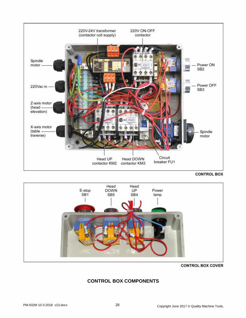
CONTROL BOX COMPONENTS

Copyright June 2017 © Quality Machine Tools,
LLC
PM-932M 10-3-2018 v13.docx 29
Electrical system (schematic on following page)
All switch contacts are shown in their "normal" condition (= not actuated).
The 220V ac supply to all devices except the transformer is switched by contactor KM1.
The 220V ac input to the transformer is not switched.
All push-buttons (SB) and the solenoids of contactors KM1, KM2 and KM3 are in the 24V ac circuit powered by the transformer.
The 24V circuit is protected by FU1, a resettable circuit breaker.
The E-STOP button breaks the 24V ac line, instantly de-energizing all contactors and stopping all machine motion.
Z-axis contactors KM2 and KM3 together form a latching circuit that positively ensures that UP and DOWN motions cannot selected at the same time. Example:
SB4 is pressed for UP motion. Contact SB4(1) closes, completing the 24V circuit to KM2 solenoid via
SB5(2), high-limit switch (3), and KM3(4). KM2 energizes, opening KM2(7), disabling the DOWN circuit
by breaking the 24V line to KM3 solenoid. Contacts KM2(8) and KM2(9) close, powering the Z-axis
motor.
The 6F capacitor on the Z-axis motor phase-shifts the 220V supply for UP vs. DOWN motion.
SPINDLE MOTOR CAPACITORS
Z-AXIS MOTOR & LIMIT SWITCH
WIRING
(back of column)

Copyright June 2017 © Quality Machine Tools,
LLC
PM-932M 10-3-2018 v13.docx 30

Copyright June 2017 © Quality Machine Tools,
LLC
PM-932M 10-3-2018 v13.docx 31
Section 5 INSTALLATION
THESE ARE THE MAIN POINTS TO WATCH OUT FOR! But read the following pages for more information
Handling the mill is at least a two-man job.
Hand-crank the headstock down until the spindle nose is just clear of the table.
Remove the hand crank, and set it aside.
Lifting gear – sling, hoist or forklift – must be rated for at least 1500 lb.
Working location of the mill must allow:
1. Full left-right travel of the table
2. Access to the back of the column (Z axis leadscrew maintenance)
3. Headroom for the Z-axis motor
Power requirement is 220V, 60Hz, 1φ, 15A circuit protection (spindle motor
only, 8.6A full load).
Extension cord not recommended; if no alternative, use 12 AWG not longer
than 20 ft.
Before connecting power be sure that:
1. The machine is on a firm footing.
2. The Z-axis (headstock) and X-axis (table) motors are safely situated, not
installed in their working locations. Don't let them dangle on the cables!
3. There are no clamps or locks on moving parts.
4. The gearbox contains oil – check the sight glass at right of the headstock.
5. The gear levers are set for the lowest speed: Hi-Lo to L, 1-2-3 to 1.
6. The gears are fully engaged – hand rotate the spindle forward and back
while applying light pressure on each lever, listening for the click as gears
engage.

Copyright June 2017 © Quality Machine Tools,
LLC
PM-932M 10-3-2018 v13.docx 32
Uncrating the mill
The PM-932M is shipped in two packing cases strapped together, the lower case for the machine, the upper one
for the stand. If available, use a forklift to remove the base. If not, an "engine hoist" such as that shown in Figure
5-1 may be used.
Setting up the stand
A suggested procedure:
1. Lower the stand packing case onto a dolly or pallet jack.
2. Remove the packing materials, then roll the stand to its working
location.
3. Slide the stand off the dolly or pallet jack.
The stand comprises two iron castings, a hollow casing and a tray.
The back side of the casing has holes for piping and wiring to and
from a (coolant) pump which may be located within the casing. A
coolant drainpipe is provided in the tray casting. Rotate the tray to
bring the drain to the back.
Check local codes for "machine tool" fastening requirements. If
none is specified, you may wish to install leveling mounts. Use
mounts with a 1/2-13 threaded stem, and a load capacity of not
less than 400 lb per mount. Mounts with a smooth underside
such as nylon allow minor repositioning even with the mill in
place. Thread length should be about 3 inches (longer stems
Figure 5-1 One method of removing the upper packing case
A nylon sling encircles two webbing straps with ratchet tensioners. To bring the hook and
chain over the center of the main packing case, the hoist was set to its fullest extension (1
ton max load), and the front wheels were elevated by 6x6 studs on either side of the pallet.
Figure 5-2 Leveling mounts
Because the mounting holes are not threaded,
a nut and washer are needed on the underside,
plus a locknut arrangement on top to prevent
rotation when the bottom nut is turned.

Copyright June 2017 © Quality Machine Tools,
LLC
PM-932M 10-3-2018 v13.docx 33
won't fit in the pockets).
With the stand in its approximate working location, level it using the rim of the tray casting. Final leveling should
be done when the machine is installed and bolted to the stand.
Preparing the mill
The following assumes an engine hoist will be used. A suggested procedure:
1. With the mill remaining on the shipping pallet, remove all packing materials except for the single sheet under
the mill.
2. Check that the headstock (Z-axis) is fully lowered (spindle nose just clear of the table), then run a sling
"basket style" under the graduated tilt collar at the back of the headstock. Caution: Wrap a soft cloth around
the sling to prevent damage to the tilt scale.
3. SLOWLY lift the mill, controlling any tendency for it to swing as it clears the pallet.
4. Remove the shipping pallet, then lower the mill onto a dolly or pallet jack.
5. OPTIONAL STEP: While the mill is near ground level, visually inspect all components – especially those that
will be difficult to access once the mill is installed on its stand, see below.
Timesaving suggestion
The tray casting slides freely on top of the stand. This makes it difficult to keep
the holes aligned when the mill is lowered into place. One way to save effort is
to install all-thread M12 x 1.75 screws in two diagonally opposite corners with
the threads uppermost (for access to the threaded holes in the stand, remove
one of the stand side panels). Thread the screws in until they protrude just
enough to stop the tray sliding around. Another way to achieve the same result
is to tap in two wood dowels from above. The dowels must be sized to allow
them to be driven through when the time comes to install the mounting bolts on
the mill.
Initial inspection and cleanup
This is a good time to work on the Z-axis leadscrew and other parts of
the column. Remove the column cap (four M8 screws) and the rear
cover (six M5 screws). Clean off all grease from the leadscrew nut and
hand-crank helical gears. The next step is easier if you first remove the
external retaining ring and coupler components from the top of the
leadscrew. Cover the leadscrew down to the nut with a taped-up sleeve
of polyethylene, then remove all casting and/or machining residue using
scrapers, wire brushes and a shop vacuum. Finally, "detail clean" the
helical gears using a stiff nylon brush such as a flux applicator. Remove
the sleeve from the leadscrew. Re-grease the gears and oil the
leadscrew. Reassemble the coupler components, then test-fit the Z-axis
motor. Check for hole alignment – the leadscrew may have been
displaced in shipping, correctable by light pushing and pulling on the
coupler at the upper end of the leadscrew. Do not install the motor at
this time.
Figure 5-3 Leadscrew and helical gears
The leadscrew nut, arrowed, is attached to
the headstock.

Copyright June 2017 © Quality Machine Tools,
LLC
PM-932M 10-3-2018 v13.docx 34
Installing the mill
1. Raise the mill to just clear the stand tray casting,
then roll the mill into position.
2. Lower the mill onto the tray using taper drift(s) to
align the mounting holes.
3. Remove the two temporary tray-locating
screws/dowels, if fitted, then install the four
mounting M12 x 190 bolts with washers.
Final assembly and cleanup
Unfinished metal surfaces are protected by thick grease and/or paper. Carefully remove these using a plastic
paint scraper, disposable rags and a light-oil type degreaser such as WD-40. Install the X axis and Y axis
handwheels. Level the mill using the table surface for reference. Oil the ways and leadscrews.
Installing the power feed (X-axis) motor
Installing the X-axis power feed motor takes care and
attention. The mounting bracket, a casting with two
hex-head clamp screws, is pre-installed. On the out-
facing surface of the bracket loosely install two hex-
head M8 screws with split and plain washers. The
motor assembly hooks onto these screws, and is
carefully lowered to engage its drive pinion with the
larger pinion pre-installed on the X-axis leadscrew. To
prevent the gears meshing too tightly, place a
greased strip of standard bond paper (about 0.004"
thick) between them before gently pressing down on
the assembly. Tighten the screws, then crank the X
handwheel to remove the paper.
Figure 5-4 Lowering mill onto stand tray
The sling, with soft cloth padding, runs under the tilt collar at the
back of the headstock. Note the X-axis motor, left, and Z-axis
motor, right. These are installed after the mill is bolted down.
Moving the mill when attached to the stand
Instead of unbolting the mill, save time by fork-
lifting the entire assembly. You will need two 1"
diameter steel rods about 40" long. These will span
the stand (hole locations arrowed in Figure 5-4)
with 8 or 9 inches clear each side of the tray. Be
careful with balance – crank the headstock down
as far as it will go.
Figure 5-5 X-axis power feed motor (table traverse)
Shims on both sides of the bracket, arrowed, may be
required to achieve quiet meshing of the gears.
Copyright June 2017 © Quality Machine Tools,
LLC
PM-932M 10-3-2018 v13.docx 35
Do not power the X-axis motor at this time!
Crank the handwheel a few turns in both directions. If the motor is properly installed, there should be little
resistance on the handwheel, and no noise other than what can be expected of straight-cut gears. If other
noises are heard, it may be that the motor is slightly tilted down. This may be correctable by tightening the
attachment screws. If not, it may be necessary to insert metal shims (say 0.005") between the mounting bracket
and motor assembly – location arrowed in photo.
Installing the head elevation (Z-axis) motor
Key the gearbox output shaft to the leadscrew coupler, then hand-crank the leadscrew as necessary to align the
bolt holes. Install and tighten the four M8 x 25 bolts.
REMOVE the crank handle before running the motor
Power-up procedure
Depending on the available 220V wall outlet, install a 6-15 or 6-20 plug on the mill power cord. Be sure the
green/yellow ground wire is attached (it may be tagged PE = Protective Earth).
Before connecting power be sure that:
1. The spindle (main) motor switch, lower right of the control panel, is set to S.
2. The Z-axis crank handle is removed.
3. There are no clamps or locks on moving parts.
4. The gearbox contains oil – check the sight glass at right of the headstock.
5. The gear levers are set for the lowest speed: Hi-Lo to L, 1-2-3 to 1.
6. The gears are fully engaged – hand rotate the spindle forward and back while applying light
pressure on each lever, listening for the click as gears engage.
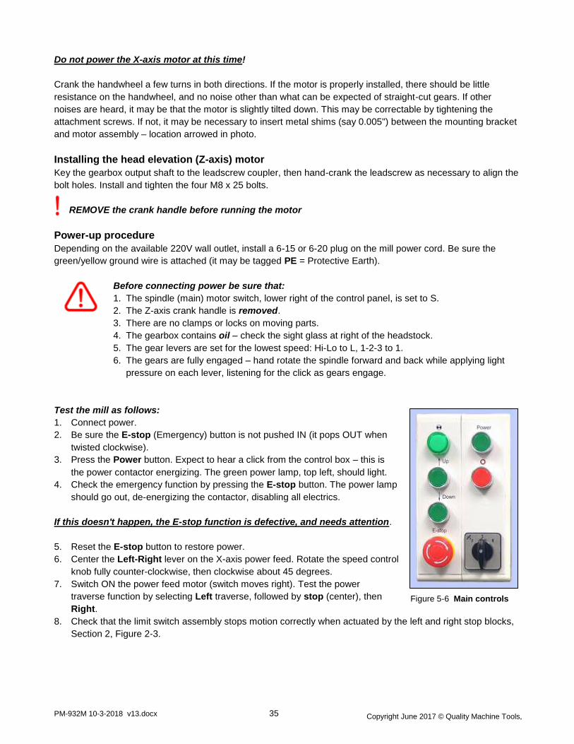
Test the mill as follows:
1. Connect power.
2. Be sure the E-stop (Emergency) button is not pushed IN (it pops OUT when
twisted clockwise).
3. Press the Power button. Expect to hear a click from the control box – this is
the power contactor energizing. The green power lamp, top left, should light.
4. Check the emergency function by pressing the E-stop button. The power lamp
should go out, de-energizing the contactor, disabling all electrics.
If this doesn't happen, the E-stop function is defective, and needs attention.
5. Reset the E-stop button to restore power.
6. Center the Left-Right lever on the X-axis power feed. Rotate the speed control
knob fully counter-clockwise, then clockwise about 45 degrees.
7. Switch ON the power feed motor (switch moves right). Test the power
traverse function by selecting Left traverse, followed by stop (center), then
Right.
8. Check that the limit switch assembly stops motion correctly when actuated by the left and right stop blocks,
Section 2, Figure 2-3.
Figure 5-6 Main controls

Copyright June 2017 © Quality Machine Tools,
LLC
PM-932M 10-3-2018 v13.docx 36
9. Crank handle removed? Headstock locking screws
loosened? Press and hold the Up button to run the
headstock up the column. Check that the motor stops as
the upper limit switch is actuated, Figure 5-7.
10. Check for no obstructions, then press and hold the Down
button to run the headstock down to the lower limit.
Expect to hear a click from the control box when
the Up button is pressed. This is one of the two
Z-axis motor contactors energizing. A similar
click from the other contactor should be heard
when the Down button is pressed.
Test run procedure
DO NOT LEAVE THE MACHINE UNATTENDED DURING THIS PROCEDURE
1. Gear levers set to L and 1 (90 rpm)? Gears fully engaged?
Test the spindle motor by setting the motor switch, lower right, to F (forward) and R (reverse) in turn.
2. Run the spindle at 90 rpm for a few minutes, then stop.
3. Select each of the available speeds in turn (L-2, L-3, H-1, etc.). Check gear engagement each time, then run
for a few minutes.
The machine should now be ready for normal operations.
Figure 5-7 Z-axis (elevation) limit switches
These are actuated by the radiused block attached
to the headstock, arrowed.
OPTIONAL STEP
When the test run is completed, you may wish to drain the oil to
flush out any residue from the manufacturing process. This is
standard practice in many shops. There are no specific data to
support this, but it may result in smoother, quieter running, together
with longer service life.
Refill the gearbox with the recommended oil, page 14.