heat transfer of bio-oil in a direct contact heat ... · heat transfer of bio-oil in a direct...
TRANSCRIPT
1159
Korean J. Chem. Eng., 33(4), 1159-1169 (2016)DOI: 10.1007/s11814-015-0256-y
pISSN: 0256-1115eISSN: 1975-7220
INVITED REVIEW PAPER
†To whom correspondence should be addressed.E-mail: [email protected] by The Korean Institute of Chemical Engineers.
Heat transfer of bio-oil in a direct contact heat exchanger during condensation
Hoon Chae Park, Hang Seok Choi†, and Ji Eun Lee
Department of Environmental Engineering, Yonsei University, Wonju 26493, Korea(Received 7 May 2015 • accepted 26 November 2015)
Abstract−Rapid quenching of volatiles in fast pyrolysis is important for achieving high yield and quality of the bio-oilproduct, but few studies have examined the condensation of volatiles and their related heat exchangers. Accordingly, wehave studied the condensation characteristics of volatiles by varying heat transfer conditions in a direct contact heatexchanger. As the mass flow rate ratio of quenching oil to pyrolysis gas increased, the heat transfer rate and yield ofbio-oil increased. The heat transfer rate and yield of bio-oil reached a maximum value at an intermediate air-to-quenching oil mass flow rate ratio. Additionally, the heat transfer rate and yield of bio-oil decreased as the temperatureof the quenching oil increased. Experiments were also conducted to derive an empirical relationship for the volumetricheat transfer coefficient for direct contact heat exchangers.
Keywords: Bio-oil, Direct Contact Heat Exchanger, Fast Pyrolysis, Heat Transfer
INTRODUCTION
The current reliance on fossil fuels contributes to environmen-tal problems, such as climate change, air pollution, and resourcedepletion. Hence, as an alternative energy source, bio-energy hasgained much attention. Some thermochemical conversion meth-ods have been developed to convert biomass into energy, such asdirect combustion, gasification, and pyrolysis. Many studies havefocused on the fast pyrolysis of biomass, through which biomass isdecomposed into useful compounds in the liquid, solid, and gasstates by using a combination of heat and O2-free conditions [1].This fast pyrolysis process produces bio-oil, which can be directlyused for generating heat and power [2]. However, this process hasmany specific requirements, including appropriate pyrolysis tem-perature, rapid heating rate, short residence time of volatiles, andrapid condensation of volatiles [3]. Although the most appropri-ate fast pyrolysis temperature varies according to the type of bio-mass, temperatures in the range of 400 to 500 oC are generally applied[4]. Fast pyrolysis also requires a rapid heating rate that is morethan 1,000 oC/s [5]. To minimize the cracking of volatiles into non-condensable gas or char via secondary reactions, the reactors mustlimit the residence time of volatiles to less than 2 s [6]. Addition-ally, volatiles should be rapidly condensed to maintain the bio-oilyield [7]. In bio-oil production, the rapid condensation of volatilesis one of the most important requirements. Both the time that vol-atiles reside in the reactor and the temperature at which the vola-tiles condense influence the composition and quality of the bio-oilproducts.
Direct and indirect contact heat exchangers are widely used forvarious commercial purposes. During the fast pyrolysis process,volatiles can be quenched by a direct or indirect contact heat ex-
changer. Direct contact heat exchangers have a number of advan-tages over the indirect, including simpler design, lower capital andmaintenance costs, higher specific heat transfer areas, and higherheat transfer rates [8]. In the fast pyrolysis process, serious plug-ging problems can occur when certain indirect contact heat ex-changers, such as the shell and tube heat exchanger, are used. Theseplugging problems can hinder steady and continuous operation.Hence, several types of direct contact heat exchangers are used inthe fast pyrolysis process. Few studies, however, have investigatedthe condensation characteristics of different direct contact heatexchangers for the quenching of fast pyrolysis volatiles. Under-standing the condensation heat transfer and the consequent per-formance of heat exchangers is important for designing a highlyefficient heat exchanger and predicting its performance. However,the complex physical phenomena that accompany gas-solid multi-phase flows have hindered studies on the condensation of volatilesin the fast pyrolysis process. Most studies have focused on the effectsof condensation temperature on the yield and physicochemicalcharacteristics of bio-oil. For instance, Zhang et al. [9] and Asadul-lah et al. [10] connected heat exchangers in series to collect vola-tiles and study the yield and physicochemical characteristics ofbio-oil, whereas Salehi et al. [11] and Boateng et al. [12] examinedthe yield and moisture content of bio-oil according to condensa-tion temperature. Westerhof et al. [13] used a direct contact heatexchanger to study the moisture content of bio-oil after varying thecondensation temperature, the volume of volatiles, and the moisturecontent of the samples. Lu et al. [14] and Zheng et al. [15] usedhybrid heat exchangers that combined direct contact heat exchang-ers with a shell and tube heat exchanger to examine changes inkinematic viscosity according to the temperature of the condensedbio-oil, in addition to variations of kinematic viscosity and moisturecontent over storage time. Direct contact heat exchangers includesingle and fractional (i.e., multi-step) heat exchangers. Fractionalheat exchangers result in two streams with well-defined boilingpoint distributions. For example, the first step heat exchanger oper-
1160 H. C. Park et al.
April, 2016
ates between 40 and 90 oC, and the second step heat exchangeroperates between 20 and 30 oC [16]. Fractional heat exchangershave been used in the initial separation step in fast pyrolysis pro-cesses for upgrading bio-oil into fuels and chemicals [17]. Re-cently, Karlsson and Nilsson [18] and Gustavsson and Nilsson [19]studied the co-production of bio-oil in district heating plants usingfractional heat exchangers. Karlsson and Nilsson [18] investigatedthe potential of utilizing waste heat from bio-oil heat exchangersfor district cooling. Gustavsson and Nilsson [19] evaluated the im-pact of pyrolysis integration into plants in terms of pyrolysis oilproduction, power generation, biomass consumption, and overallenergy efficiency.
The majority of studies on fast pyrolysis have focused on opti-mizing the characteristics of fast pyrolyzers to increase the yieldand quality of bio-oil [20,21]. However, the condensation processitself is also an extremely important aspect to consider when design-ing a fast pyrolysis plant. To minimize secondary reactions andmaximize oil yields, volatiles must be quenched very rapidly. How-ever, our knowledge regarding volatile condensation after fast pyroly-sis is incomplete owing to the complicated physical phenomenainvolved in this process. In this study, we examined the condensa-tion heat transfer characteristics of volatiles while using a directcontact heat exchanger. In particular, we aim to derive the volu-metric heat transfer coefficient of a direct contact heat exchanger,which will be required for the optimal design of direct contactheat exchangers in a full-scale plant.
MATERIALS AND METHODS
1. MaterialsIn this study, fast pyrolysis of larch sawdust was performed. A
standard sieve (ASTM E-11-61) was used to separate larch parti-cles according to size; particles of 1-2mm size were used. To removethe initial moisture, the raw material was dried in an oven at 105±5 oC for 24 h. The physical and chemical properties of the rawmaterial are given in Table 1; the physicochemical characteristicsof bio-oil, which were collected after the fast pyrolysis of larch saw-
dust, are given in Table 2. Table 2 shows the characteristics of bio-oil condensed under the following conditions: / =0.2,
/ =4, and a quenching oil temperature of 45 oC. The charac-teristics of bio-oil change according to the operating conditions ofthe direct contact heat exchanger. Sufficient bio-oil was not avail-able for us to use in the direct contact exchanger during the initialstage of operation. Therefore, process oil that can be used insteadof the bio-oil was required. For the direct contact heat exchanger,paraffin process oil, which does not dissolve in bio-oil, wasselected as the quenching oil. The characteristics of paraffin pro-cess oil are shown in Table 3.2. Experimental Method
The experimental apparatus for the fast pyrolysis system, whichused a bubbling fluidized bed reactor, is shown in Fig. 1. In thisapparatus, a silo containing larch particles, and two screw feedersof identical size and configuration supplied larch particles into thebubbling fluidized bed reactor. The upper feeder controlled thefeed rate of larch particles, and the lower one transported them intothe fluidized bed reactor. The reactor was constructed of stainlesssteel (SUS-304) and its diameter and height were 70 mm and210 mm, respectively. The reactor was filled with 320 g of silicasand and heated with an electric heater to maintain the reactiontemperature at 500 oC for fast pyrolysis. The residence time of thegas stream, including permanent gases and volatiles, was less than
m· air m· qo
m· qo m· g
Table 2. Characteristics of the bio-oilMoisture content (wt%) 5.96Density (kg/m3) 1260
Elementalcomposition (wt%)
C 56.25H 10.18N -O 33.5
LHV (MJ/kg) 21.61Viscosity (mPa·s, at 50 oC) 115.9pH 2.7Solids (wt%) 0.03Ash content (wt%) 0.002
* Condensation conditions: =0.2, =4, Quenchingoil temperature=45 oC
m· air/m· qo m· qo/m· g
Table 1. Characteristics of the raw material (larch particles)Particle size (mm) 1-2Bulk density (kg/m3) 314High heating value, HHV (MJ/kg) 16.52Proximate analysis (wt%)Water 03.19Volatile 78.58Fixed carbon 17.09Ash 01.15Ultimate analysis (dry basis wt%)C 47.12H 06.00O 46.77N 00.11S -
Table 3. Quenching oil characteristics
Product type Hydrocarbon mixture(Mineral oil)
Hydrocarbonelement
Paraffin, % 65Naphthene, % 34Aromatic, % 1
Solubility in water NegligiblePour point (oC) 210Density (kg/m3) 862Specific heat (kJ/kg-K) 1.884Kinematic viscosity (mm2/s, at 20 oC) 30.2Lower heating value, LHV (MJ/kg) 47.31
Heat transfer of bio-oil in a direct contact heat exchanger during condensation 1161
Korean J. Chem. Eng.(Vol. 33, No. 4)
2 s. A cyclone separated and collected the char particles that weredispersed in the gas stream. The volatiles were condensed by coldparaffin oil droplets in a direct contact heat exchanger before col-lection of the condensed bio-oil. An electrostatic precipitator wasused to trap the fine oil mist before it reached the vent.
To enable the observation of condensation phenomena, the directcontact heat exchanger was made of transparent acryl. Its diame-ter was 150 mm, and the height was 1,000 mm. Two air atomizernozzles were placed on the head of the heat exchanger for atomiz-ing and spraying paraffin oil over the incoming gas stream. Theoil spray system consisted of a chiller, an oil pump, and sprayingnozzles. The temperature of the quenching oil was controlled bythe temperature controller of the chiller. The atomizer nozzle gen-erated fine oil droplets to increase their contact surface. The speci-fications of the nozzle are given in Table 4. To measure the tem-peratures of the gas stream and quenching oil, K-type thermocou-ples were placed at the inlet and outlet of the heat exchanger. Fouradditional thermocouples were also installed at regular intervalsinside the heat exchanger. To prevent the condensation of volatilesbefore reaching the heat exchanger [22], pipe lines between the
reactor and the heat exchanger were heated to above 240 oC.The experimental conditions for the fast pyrolysis of larch parti-
cles and direct contact condensation are listed in Table 5. The fastpyrolysis parameters were chosen to maximize the yield of bio-oiland were obtained from previous experiments [23,24]. A singlefraction of bio-oil contains water from the process as well as all ofthe chemical compounds that are found in fast pyrolysis bio-oil.The goal of fractionating bio-oil is to separate the bio-oil into dis-tinct fractions that contain different families of chemical compounds.A single or fractional heat exchanger can be used, depending onthe final purpose of the bio-oil. A fractional heat exchanger can beused for upgraded bio-oil or in connection with district heating[25]. However, a single heat exchanger can be used for co-com-busting the bio-oil in a boiler in an economical way [25]. The pur-pose of this study was to produce bio-oil at a low price withoutadditional equipment because it focuses on producing bio-oil for
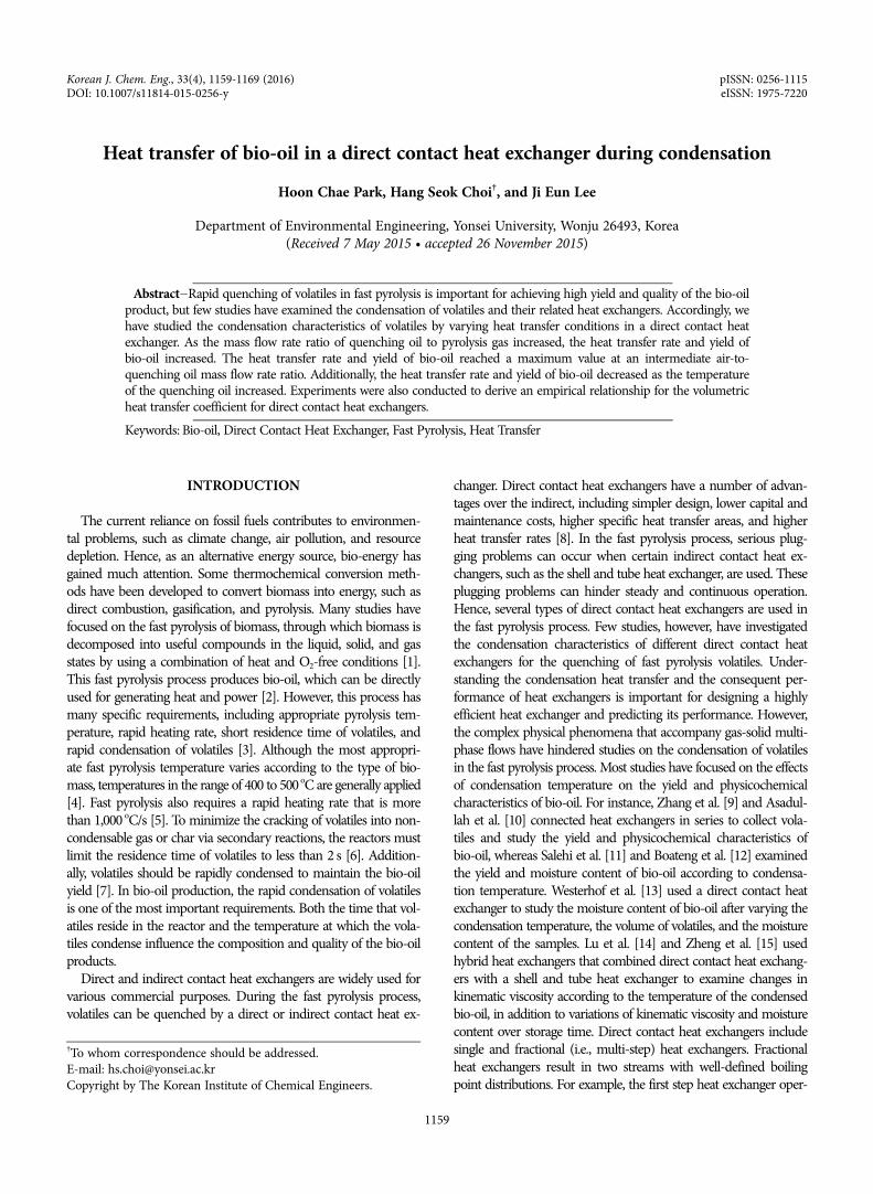
Fig. 1. Schematic diagram of the experimental apparatus.1. N2 gas vessel 4. Bubbling fluidized bed reactor 7. Oil pump2. Silo 5. Cyclone 8. Chiller3. Screw feeder 6. Direct contact heat exchanger 9. Electrostatic precipitator
Table 4. Specifications of the atomizer nozzleSpray type Full coneSpray angle 20o
Material Stainless steelManufacturer Hanmi Nozzle, Korea
Table 5. Experimental conditions for the fast pyrolysis of larch par-ticles and direct contact condensation
Fast pyrolysis
Pyrolysis temperature (oC) 500Particle size (mm) 1-2N2 flow rate (L/min) 20Larch particle feeding rate (g/min) 3.3
Direct contactcondensation
1, 2, 3, 40.1, 0.2, 0.3, 0.4
Quenching oil temperature (oC) 15, 25, 35, 45
m· qo/m· g
m· air/m· qo
1162 H. C. Park et al.
April, 2016
co-combustion in a boiler. To achieve this goal, operating the heatexchanger at the ambient temperature can be economical. There-fore, the condensation temperature was selected as 15-45 oC. Themass flow rate ratios of the quenching oil to the pyrolysis gas ( /
) are given in Table 5. In these ratios, the mass flow rate of thequenching oil was varied, while that of the pyrolysis gas was main-tained at a constant value. The mass flow rate of the pyrolysis gas( ) was calculated from the bio-oil mass (mbio-oil), char mass (mchar),feeding time (tfeed), and raw material mass (mfeed) as
(1)
To determine the influence of the ratio / and quenching oiltemperature, the ratio / and quenching oil temperature werevaried during the experiments, while the ratio / was fixed at0.2. Hence, the atomizing performance and droplet size of the nozzlewere almost the same in all cases. In the ratio / , the air massflow rate was varied, while that of the quenching oil was fixed.
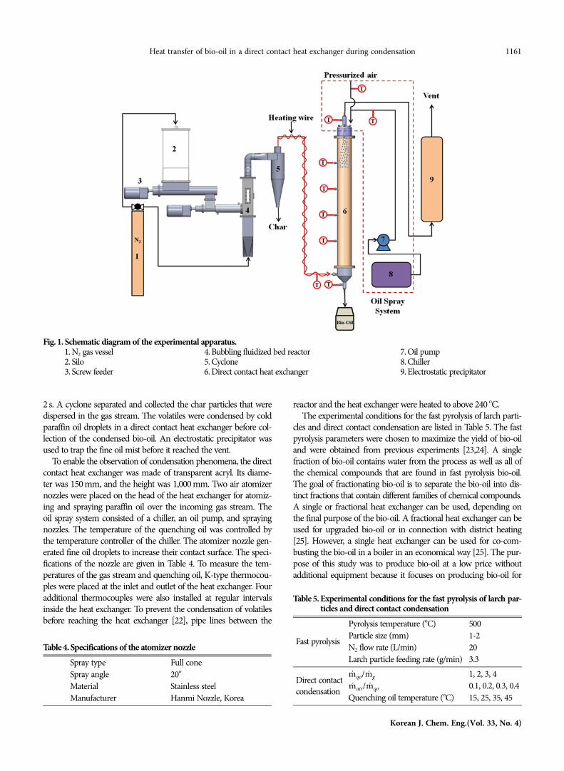
Direct contact condensation is initiated when the temperaturesof the reactor and quenching oil are stably maintained. Bio-oil,which is condensed in the direct contact heat exchanger, is col-lected as a mixture of bio-oil and quenching oil in a conical flaskat the bottom of the heat exchanger. A mixture of bio-oil (ρ=1,260kg/m3) and quenching oil (ρ=860 kg/m3) is shown in Fig. 2(a).After a certain period of time, the mixture separates into two lay-ers according to density, as shown in Fig. 2(b).3. Calculation of the Heat Transfer Coefficient
The volumetric heat transfer coefficient (UV) of a direct contactheat exchanger is defined as [26]
(2)
where Q is the heat transfer rate, V is the volume of the direct
contact heat exchanger, and ΔTlm is the log mean temperature dif-ference. The heat transfer rate (Q) is the summation of all latentheat (released or absorbed during the phase change of the vola-tiles) and sensible heat (transferred by the temperature differ-ences). Heat loss from the heat exchanger to the outside was as-sumed to be negligible; additionally, heat transfer was assumed tooccur only among the pyrolyzed gas stream, air, and quenchingoil. The rate of heat loss from the pyrolysis gas was equal to therate of heat gain by the quenching oil and the air that was injectedthrough the spray nozzle. Under these assumptions, based on thefirst law of thermodynamics [26], the heat released from the pyro-lyzed gas stream can be expressed as
(3a)
where subscript v indicates volatile gas, ncg indicates non-con-densable gas, i represents the species of the volatile gas, and j rep-resents the species of the non-condensable gas. Additionally, theheat absorbed by the quenching oil and air can be expressed as
(3b)
The volumetric heat transfer coefficient was calculated by measur-ing the heat transfer rates and the log mean temperature differences:
(4)
The heat transfer rates of the quenching oil and the air were calcu-lated by measuring the mass flow rates of the quenching oil and theair injected from the nozzle as well as the inlet and outlet tempera-tures of the quenching oil and air. These parameters were meas-ured at the top and bottom of the direct contact heat exchanger. Thequenching oil and the condensed bio-oil were mixed and thendrained into the bottom of the direct contact heat exchanger. Theair and non-condensed gases were also mixed and released from thetop of the direct contact heat exchanger. Measuring the individualtemperatures of fluids in a mixed state is technically challenging.Therefore, the mixed fluids were assumed to be in thermal equi-librium at the inlet and outlet. The air and quenching oil releasedfrom the nozzle were also assumed to have the same temperature.
The latent heat and specific heat capacity are essential parame-ters in the design of heat exchangers. Only limited reports are avail-able on the specific heat capacity. According to Lu et al. [27], thespecific heat capacity of bio-oil may be 2.5-3.5 kJ/kg-K in the tem-perature range of 20-60 oC. The latent heat of bio-oil, calculatedwith the heat capacity and Eq. (3a), is 840 kJ/kg. For reference,Zhang [28] studied the latent heat of chemical components of bio-oil. According to Zhang’s results, the latent heat ranges from 481 to1,159 kJ/kg. Hence, the calculated value of the latent heat can beconsidered reasonable.4. Measurement of Quenching Oil Droplet Diameter
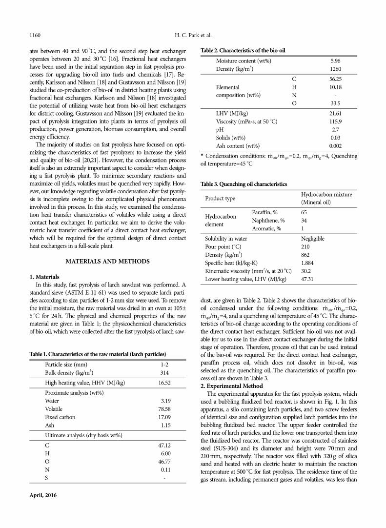
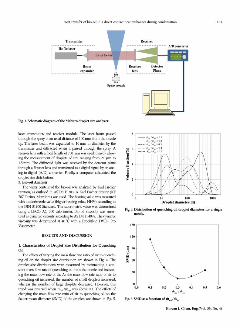
A droplet size analyzer (Malvern Spraytec) was used to mea-sure the diameters of the quenching oil droplets released from theatomizer nozzles. The analyzer (see Fig. 3) consisted of a He-Ne
m· qo
m· g
m· g
m· g = mg
tfeed--------, mg = mfeed − mbio-oil + mchar( ).
m· qo m· g
m· qo m· g
m· air m· qo
m· air m· qo
UV = Q
VΔTlm----------------,
Q = Qg, latent + Qg, sensible
⎧ ⎪ ⎪ ⎨ ⎪ ⎪ ⎪ ⎩
= m· ghfg + m· gCp, g Tg, in − Tg, out( )
= m· vihfgi + m· g − m· v( )Yj Cp, ncgj Tncgj, in − Tncgj, out( )j=1
m∑
i=1
n∑
Q = Qqo + Qair⎧ ⎪ ⎨ ⎪ ⎩
= m· qoCp, qo Tqo, out − Tqo, in( ) + m· airCp, air Tqo, out − Tqo, in( )
ΔTlm = ΔT1− ΔT2
ΔT1/ΔT2( )ln------------------------------, ΔT1= Tg, in − Tqo, out, ΔT2 = Tg, out − Tqo, in.
Fig. 2. Collected oil mixture.(a) Oil mixture (b) Separated oils
Heat transfer of bio-oil in a direct contact heat exchanger during condensation 1163
Korean J. Chem. Eng.(Vol. 33, No. 4)
laser, transmitter, and receiver module. The laser beam passedthrough the spray at an axial distance of 100 mm from the nozzletip. The laser beam was expanded to 10 mm in diameter by thetransmitter and diffracted when it passed through the spray. Areceiver lens with a focal length of 750mm was used, thereby allow-ing the measurement of droplets of size ranging from 2.0μm to1.5 mm. The diffracted light was received by the detector planethrough a Fourier lens and transferred to a digital signal by an ana-log-to-digital (A/D) converter. Finally, a computer calculated thedroplet size distribution.5. Bio-oil Analysis
The water content of the bio-oil was analyzed by Karl Fischertitration, as outlined in ASTM E 203. A Karl Fischer titrator (KF787 Titrino, Metrohm) was used. The heating value was measuredwith a calorimetric value (higher heating value, HHV) according tothe DIN 51900 Standard. The calorimetric value was determinedusing a LECO AC 300 calorimeter. Bio-oil viscosity was meas-ured as dynamic viscosity according to ASTM D 4878. The dynamicviscosity was determined at 40 oC with a Brookfield DVII+ ProViscometer.
RESULTS AND DISCUSSION
1. Characteristics of Droplet Size Distribution for QuenchingOil
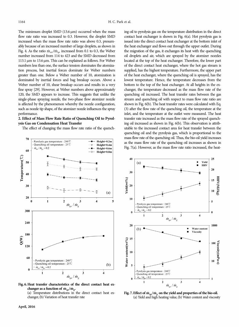
The effects of varying the mass flow rate ratio of air to quench-ing oil on the droplet size distribution are shown in Fig. 4. Thedroplet size distributions were measured by maintaining a con-stant mass flow rate of quenching oil from the nozzle and increas-ing the mass flow rate of air. As the mass flow rate ratio of air toquenching oil increased, the number of small droplets increased,whereas the number of large droplets decreased. However, thistrend was reversed when / was above 0.3. The effects ofchanging the mass flow rate ratio of air to quenching oil on theSauter mean diameter (SMD) of the droplets are shown in Fig. 5.
m· air m· qo
Fig. 3. Schematic diagram of the Malvern droplet size analyzer.
Fig. 4. Distribution of quenching oil droplet diameters for a singlenozzle.
Fig. 5. SMD as a function of m· air/m· qo.
1164 H. C. Park et al.
April, 2016
The minimum droplet SMD (13.6μm) occurred when the massflow rate ratio was increased to 0.3. However, the droplet SMDincreased when the mass flow rate ratio was above 0.3, presum-ably because of an increased number of large droplets, as shown inFig. 4. As the ratio / increased from 0.1 to 0.3, the Webernumber increased from 114 to 423 and the SMD decreased from113.1μm to 13.6μm. This can be explained as follows. For Webernumbers less than one, the surface tension dominates the atomiza-tion process, but inertial forces dominate for Weber numbersgreater than one. Below a Weber number of 10, atomization isdominated by inertial forces and bag breakup occurs. Above aWeber number of 10, shear breakup occurs and results in a veryfine spray [29]. However, at Weber numbers above approximately120, the SMD appears to increase. This suggests that unlike thesingle-phase spraying nozzle, the two-phase flow atomizer nozzleis affected by the phenomenon whereby the nozzle configuration,such as nozzle tip shape, of the atomizer nozzle influences the sprayperformance.2. Effect of Mass Flow Rate Ratio of Quenching Oil to Pyrol-ysis Gas on Condensation Heat Transfer
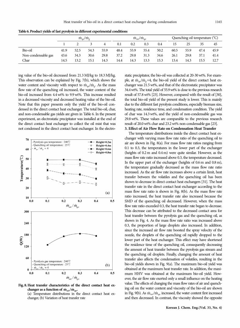
The effect of changing the mass flow rate ratio of the quench-
ing oil to pyrolysis gas on the temperature distribution in the directcontact heat exchanger is shown in Fig. 6(a). Hot pyrolysis gas isissued into the direct contact heat exchanger at the bottom inlet ofthe heat exchanger and flows out through the upper outlet. Duringthe migration of the gas, it exchanges its heat with the quenchingoil droplets and air, which are sprayed by the atomizer nozzleslocated at the top of the heat exchanger. Therefore, the lower partof the direct contact heat exchanger, where the hot gas stream issupplied, has the highest temperature. Furthermore, the upper partof the heat exchanger, where the quenching oil is sprayed, has thelowest temperature. Hence, the temperature decreases from thebottom to the top of the heat exchanger. At all heights in the ex-changer, the temperature decreased as the mass flow rate of thequenching oil increased. The heat transfer rates between the gasstream and quenching oil with respect to mass flow rate ratio areshown in Fig. 6(b). The heat transfer rates were calculated with Eq.(3) after the flow rate of the quenching oil, the temperature at theinlet, and the temperature at the outlet were measured. The heattransfer rate increased as the mass flow rate of the sprayed quench-ing oil increased as shown in Fig. 6(b). This observation is attrib-utable to the increased contact area for heat transfer between thequenching oil and the pyrolysis gas, which is proportional to themass flow rate of the quenching oil. Thus, the bio-oil yield increasesas the mass flow rate of the quenching oil increases as shown inFig. 7(a). However, as the mass flow rate ratio increased, the heat-
m· air m· qo
Fig. 6. Heat transfer characteristics of the direct contact heat ex-changer as a function of (a) Temperature distributions in the direct contact heat ex-changer, (b) Variation of heat transfer rate
m· qo/m· g.Fig. 7. Effect of on the yield and properties of the bio-oil.
(a) Yield and high heating value, (b) Water content and viscositym· qo/m· g
Heat transfer of bio-oil in a direct contact heat exchanger during condensation 1165
Korean J. Chem. Eng.(Vol. 33, No. 4)
ing value of the bio-oil decreased from 21.3 MJ/kg to 18.3 MJ/kg.This observation can be explained by Fig. 7(b), which shows thewater content and viscosity with respect to / . As the massflow rate of the quenching oil increased, the water content of thebio-oil increased from 4.4 wt% to 9.9 wt%. This increase resultedin a decreased viscosity and decreased heating value of the bio-oil.Note that this paper presents only the yield of the bio-oil con-densed in the direct contact heat exchanger. The total bio-oil, char,and non-condensable gas yields are given in Table 6. In the presentexperiment, an electrostatic precipitator was installed at the end ofthe direct contact heat exchanger to collect the oil mist that wasnot condensed in the direct contact heat exchanger. In the electro-
static precipitator, the bio-oil was collected at 20-30 wt%. For exam-ple, at / =4, the bio-oil yield of the direct contact heat ex-changer was 21.5 wt%, and that of the electrostatic precipitator was34.4wt%. The total yield of 55.9wt% is close to the previous researchresult of 57.8 wt% [23]. However, compared with the result of [30],the total bio-oil yield of the present study is lower. This is mainlydue to the different fast pyrolysis conditions, especially biomass size,heating rate, residence time, and condensation condition. The yieldof char was 14.3 wt%, and the yield of non-condensable gas was29.8 wt%. These values are comparable to the previous researchresult of 20.0 wt% char and 23.2 wt% non-condensable gas [23].3. Effect of Air Flow Rate on Condensation Heat Transfer
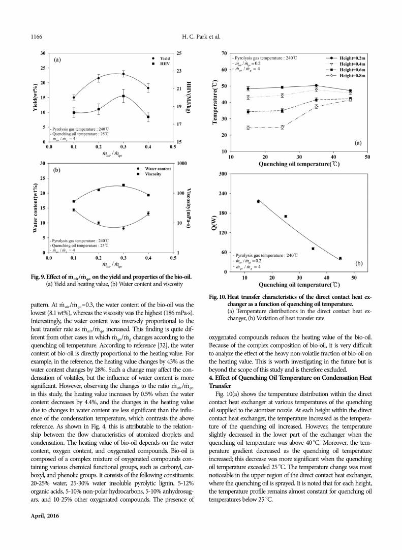
The temperature distributions inside the direct contact heat ex-changer with varying mass flow rate ratio of the quenching oil toair are shown in Fig. 8(a). For mass flow rate ratios ranging from0.1 to 0.3, the temperatures in the lower part of the exchanger(heights of 0.2 m and 0.4 m) were quite similar. However, as themass flow rate ratio increased above 0.3, the temperature decreased.In the upper part of the exchanger (heights of 0.6 m and 0.8 m),the temperature gradually decreased as the mass flow rate ratioincreased. As the air flow rate increases above a certain limit, heattransfer between the volatiles and the quenching oil has beenshown to decrease in direct contact heat exchangers [31]. The heattransfer rate in the direct contact heat exchanger according to themass flow rate ratio is shown in Fig. 8(b). As the mass flow rateratio increased, the heat transfer rate also increased because theSMD of the quenching oil decreased. However, when the massflow rate ratio exceeded 0.3, the heat transfer rate began to decrease.This decrease can be attributed to the decreased contact area forheat transfer between the pyrolysis gas and the quenching oil, asshown in Fig. 4. As the mass flow rate ratio was increased above0.3, the proportion of large droplets also increased. In addition,since the increased air flow rate boosted the spray velocity of thenozzle, the droplets of the quenching oil rapidly dropped to thelower part of the heat exchanger. This effect may have shortenedthe residence time of the quenching oil, consequently decreasingthe amount of heat transfer between the pyrolysis gas stream andthe quenching oil droplets. Finally, changing the amount of heattransfer also affects the condensation of volatiles, resulting in thebio-oil yields shown in Fig. 9(a). The maximum bio-oil yield wasobtained at the maximum heat transfer rate. In addition, the maxi-mum HHV was obtained at the maximum bio-oil yield. How-ever, the air flow rate exerted only a small influence on the heatingvalue. The effects of changing the mass flow rates of air and quench-ing oil on the water content and viscosity of the bio-oil are shownin Fig. 9(b). As / increased, the water content first increasedand then decreased. In contrast, the viscosity showed the opposite
m· qo m· g
m· qo m· g
m· air m· qo
Table 6. Product yields of fast pyrolysis in different experimental conditionsQuenching oil temperature (oC)
1 2 3 4 0.1 0.2 0.3 0.4 15 25 35 45Bio-oil 41.9 52.5 54.3 55.9 48.4 55.9 55.4 50.2 60.5 55.9 47.4 45.9Non-condensable gas 43.6 34.3 30.6 29.8 37.2 29.8 31.3 34.6 26.1 29.8 37.1 41.4Char 14.5 13.2 15.1 14.3 14.4 14.3 13.3 15.3 13.4 14.3 15.5 12.7
m· qo/m· g m· air/m· qo
Fig. 8. Heat transfer characteristics of the direct contact heat ex-changer as a function of (a) Temperature distributions in the direct contact heat ex-changer, (b) Variation of heat transfer rate
m· air/m· qo.
1166 H. C. Park et al.
April, 2016
pattern. At / =0.3, the water content of the bio-oil was thelowest (8.1 wt%), whereas the viscosity was the highest (186 mPa·s).Interestingly, the water content was inversely proportional to theheat transfer rate as / increased. This finding is quite dif-ferent from other cases in which / changes according to thequenching oil temperature. According to reference [32], the watercontent of bio-oil is directly proportional to the heating value. Forexample, in the reference, the heating value changes by 43% as thewater content changes by 28%. Such a change may affect the con-densation of volatiles, but the influence of water content is moresignificant. However, observing the changes to the ratio /in this study, the heating value increases by 0.5% when the watercontent decreases by 4.4%, and the changes in the heating valuedue to changes in water content are less significant than the influ-ence of the condensation temperature, which contrasts the abovereference. As shown in Fig. 4, this is attributable to the relation-ship between the flow characteristics of atomized droplets andcondensation. The heating value of bio-oil depends on the watercontent, oxygen content, and oxygenated compounds. Bio-oil iscomposed of a complex mixture of oxygenated compounds con-taining various chemical functional groups, such as carbonyl, car-boxyl, and phenolic groups. It consists of the following constituents:20-25% water, 25-30% water insoluble pyrolytic lignin, 5-12%organic acids, 5-10% non-polar hydrocarbons, 5-10% anhydrosug-ars, and 10-25% other oxygenated compounds. The presence of
oxygenated compounds reduces the heating value of the bio-oil.Because of the complex composition of bio-oil, it is very difficultto analyze the effect of the heavy non-volatile fraction of bio-oil onthe heating value. This is worth investigating in the future but isbeyond the scope of this study and is therefore excluded.4. Effect of Quenching Oil Temperature on Condensation HeatTransfer
Fig. 10(a) shows the temperature distribution within the directcontact heat exchanger at various temperatures of the quenchingoil supplied to the atomizer nozzle. At each height within the directcontact heat exchanger, the temperature increased as the tempera-ture of the quenching oil increased. However, the temperatureslightly decreased in the lower part of the exchanger when thequenching oil temperature was above 40 oC. Moreover, the tem-perature gradient decreased as the quenching oil temperatureincreased; this decrease was more significant when the quenchingoil temperature exceeded 25 oC. The temperature change was mostnoticeable in the upper region of the direct contact heat exchanger,where the quenching oil is sprayed. It is noted that for each height,the temperature profile remains almost constant for quenching oiltemperatures below 25 oC.
m· air m· qo
m· air m· qo
m· qo m· g
m· air m· qo
Fig. 9. Effect of on the yield and properties of the bio-oil.(a) Yield and heating value, (b) Water content and viscosity
m· air/m· qo
Fig. 10. Heat transfer characteristics of the direct contact heat ex-changer as a function of quenching oil temperature.(a) Temperature distributions in the direct contact heat ex-changer, (b) Variation of heat transfer rate
Heat transfer of bio-oil in a direct contact heat exchanger during condensation 1167
Korean J. Chem. Eng.(Vol. 33, No. 4)
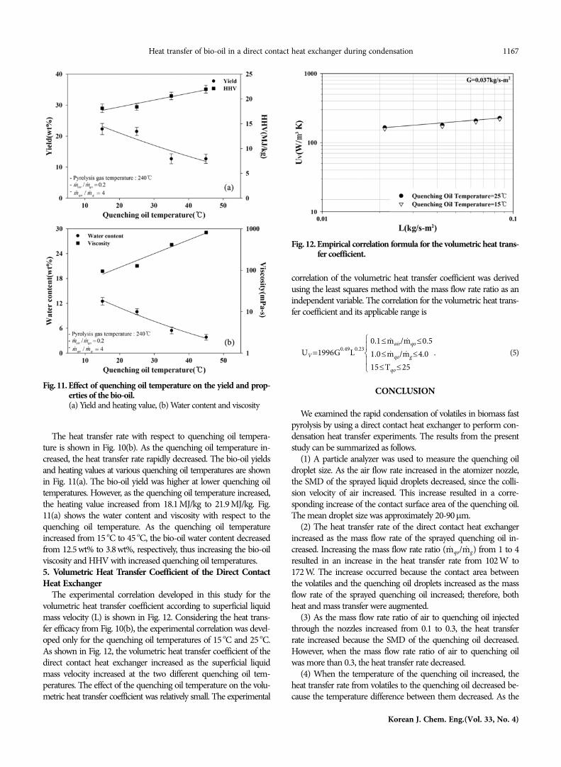
The heat transfer rate with respect to quenching oil tempera-ture is shown in Fig. 10(b). As the quenching oil temperature in-creased, the heat transfer rate rapidly decreased. The bio-oil yieldsand heating values at various quenching oil temperatures are shownin Fig. 11(a). The bio-oil yield was higher at lower quenching oiltemperatures. However, as the quenching oil temperature increased,the heating value increased from 18.1 MJ/kg to 21.9 MJ/kg. Fig.11(a) shows the water content and viscosity with respect to thequenching oil temperature. As the quenching oil temperatureincreased from 15 oC to 45 oC, the bio-oil water content decreasedfrom 12.5 wt% to 3.8 wt%, respectively, thus increasing the bio-oilviscosity and HHV with increased quenching oil temperatures.5. Volumetric Heat Transfer Coefficient of the Direct ContactHeat Exchanger
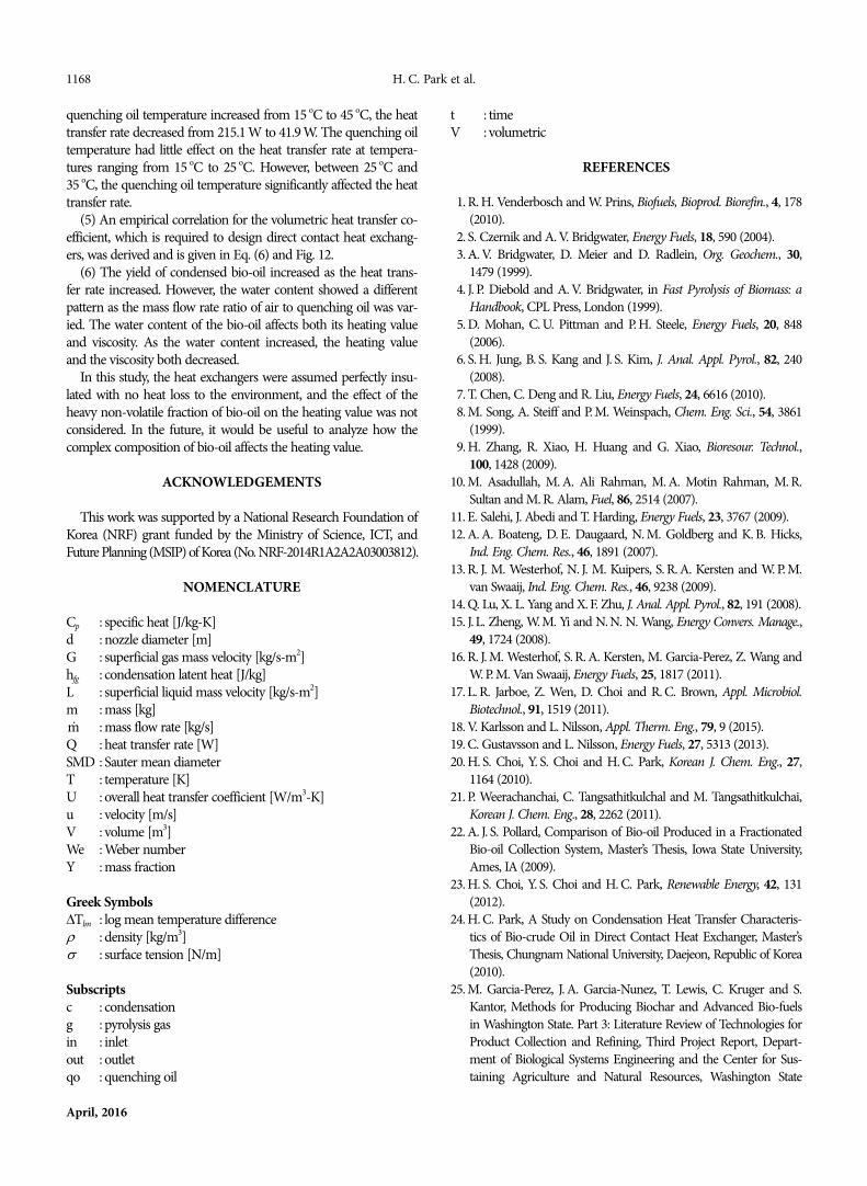
The experimental correlation developed in this study for thevolumetric heat transfer coefficient according to superficial liquidmass velocity (L) is shown in Fig. 12. Considering the heat trans-fer efficacy from Fig. 10(b), the experimental correlation was devel-oped only for the quenching oil temperatures of 15 oC and 25 oC.As shown in Fig. 12, the volumetric heat transfer coefficient of thedirect contact heat exchanger increased as the superficial liquidmass velocity increased at the two different quenching oil tem-peratures. The effect of the quenching oil temperature on the volu-metric heat transfer coefficient was relatively small. The experimental
correlation of the volumetric heat transfer coefficient was derivedusing the least squares method with the mass flow rate ratio as anindependent variable. The correlation for the volumetric heat trans-fer coefficient and its applicable range is
(5)
CONCLUSION
We examined the rapid condensation of volatiles in biomass fastpyrolysis by using a direct contact heat exchanger to perform con-densation heat transfer experiments. The results from the presentstudy can be summarized as follows.
(1) A particle analyzer was used to measure the quenching oildroplet size. As the air flow rate increased in the atomizer nozzle,the SMD of the sprayed liquid droplets decreased, since the colli-sion velocity of air increased. This increase resulted in a corre-sponding increase of the contact surface area of the quenching oil.The mean droplet size was approximately 20-90μm.
(2) The heat transfer rate of the direct contact heat exchangerincreased as the mass flow rate of the sprayed quenching oil in-creased. Increasing the mass flow rate ratio ( / ) from 1 to 4resulted in an increase in the heat transfer rate from 102 W to172 W. The increase occurred because the contact area betweenthe volatiles and the quenching oil droplets increased as the massflow rate of the sprayed quenching oil increased; therefore, bothheat and mass transfer were augmented.
(3) As the mass flow rate ratio of air to quenching oil injectedthrough the nozzles increased from 0.1 to 0.3, the heat transferrate increased because the SMD of the quenching oil decreased.However, when the mass flow rate ratio of air to quenching oilwas more than 0.3, the heat transfer rate decreased.
(4) When the temperature of the quenching oil increased, theheat transfer rate from volatiles to the quenching oil decreased be-cause the temperature difference between them decreased. As the
UV =1996G0.49L0.230.1 m· air/m· qo 0.5≤ ≤
1.0 m· qo/m· g 4.0≤ ≤
15 Tqo 25≤ ≤⎩⎪⎨⎪⎧
.
m· qo m· g
Fig. 11. Effect of quenching oil temperature on the yield and prop-erties of the bio-oil.(a) Yield and heating value, (b) Water content and viscosity
Fig. 12. Empirical correlation formula for the volumetric heat trans-fer coefficient.
1168 H. C. Park et al.
April, 2016
quenching oil temperature increased from 15 oC to 45 oC, the heattransfer rate decreased from 215.1 W to 41.9 W. The quenching oiltemperature had little effect on the heat transfer rate at tempera-tures ranging from 15 oC to 25 oC. However, between 25 oC and35 oC, the quenching oil temperature significantly affected the heattransfer rate.
(5) An empirical correlation for the volumetric heat transfer co-efficient, which is required to design direct contact heat exchang-ers, was derived and is given in Eq. (6) and Fig. 12.
(6) The yield of condensed bio-oil increased as the heat trans-fer rate increased. However, the water content showed a differentpattern as the mass flow rate ratio of air to quenching oil was var-ied. The water content of the bio-oil affects both its heating valueand viscosity. As the water content increased, the heating valueand the viscosity both decreased.
In this study, the heat exchangers were assumed perfectly insu-lated with no heat loss to the environment, and the effect of theheavy non-volatile fraction of bio-oil on the heating value was notconsidered. In the future, it would be useful to analyze how thecomplex composition of bio-oil affects the heating value.
ACKNOWLEDGEMENTS
This work was supported by a National Research Foundation ofKorea (NRF) grant funded by the Ministry of Science, ICT, andFuture Planning (MSIP) of Korea (No. NRF-2014R1A2A2A03003812).
NOMENCLATURE
Cp : specific heat [J/kg-K]d : nozzle diameter [m]G : superficial gas mass velocity [kg/s-m2]hfg : condensation latent heat [J/kg]L : superficial liquid mass velocity [kg/s-m2]m : mass [kg]
: mass flow rate [kg/s]Q : heat transfer rate [W]SMD : Sauter mean diameterT : temperature [K]U : overall heat transfer coefficient [W/m3-K]u : velocity [m/s]V : volume [m3]We : Weber numberY : mass fraction
Greek SymbolsΔTlm : log mean temperature differenceρ : density [kg/m3]σ : surface tension [N/m]
Subscriptsc : condensationg : pyrolysis gasin : inletout : outletqo : quenching oil
t : timeV : volumetric
REFERENCES
1. R. H. Venderbosch and W. Prins, Biofuels, Bioprod. Biorefin., 4, 178(2010).
2. S. Czernik and A. V. Bridgwater, Energy Fuels, 18, 590 (2004).3. A. V. Bridgwater, D. Meier and D. Radlein, Org. Geochem., 30,
1479 (1999).4. J. P. Diebold and A. V. Bridgwater, in Fast Pyrolysis of Biomass: a
Handbook, CPL Press, London (1999).5. D. Mohan, C. U. Pittman and P. H. Steele, Energy Fuels, 20, 848
(2006).6. S. H. Jung, B. S. Kang and J. S. Kim, J. Anal. Appl. Pyrol., 82, 240
(2008).7. T. Chen, C. Deng and R. Liu, Energy Fuels, 24, 6616 (2010).8. M. Song, A. Steiff and P. M. Weinspach, Chem. Eng. Sci., 54, 3861
(1999).9. H. Zhang, R. Xiao, H. Huang and G. Xiao, Bioresour. Technol.,
100, 1428 (2009).10. M. Asadullah, M. A. Ali Rahman, M. A. Motin Rahman, M. R.
Sultan and M. R. Alam, Fuel, 86, 2514 (2007).11. E. Salehi, J. Abedi and T. Harding, Energy Fuels, 23, 3767 (2009).12. A. A. Boateng, D. E. Daugaard, N. M. Goldberg and K. B. Hicks,
Ind. Eng. Chem. Res., 46, 1891 (2007).13. R. J. M. Westerhof, N. J. M. Kuipers, S. R. A. Kersten and W. P. M.
van Swaaij, Ind. Eng. Chem. Res., 46, 9238 (2009).14. Q. Lu, X. L. Yang and X. F. Zhu, J. Anal. Appl. Pyrol., 82, 191 (2008).15. J. L. Zheng, W. M. Yi and N. N. N. Wang, Energy Convers. Manage.,
49, 1724 (2008).16. R. J. M. Westerhof, S. R. A. Kersten, M. Garcia-Perez, Z. Wang and
W. P. M. Van Swaaij, Energy Fuels, 25, 1817 (2011).17. L. R. Jarboe, Z. Wen, D. Choi and R. C. Brown, Appl. Microbiol.
Biotechnol., 91, 1519 (2011).18. V. Karlsson and L. Nilsson, Appl. Therm. Eng., 79, 9 (2015).19. C. Gustavsson and L. Nilsson, Energy Fuels, 27, 5313 (2013).20. H. S. Choi, Y. S. Choi and H. C. Park, Korean J. Chem. Eng., 27,
1164 (2010).21. P. Weerachanchai, C. Tangsathitkulchal and M. Tangsathitkulchai,
Korean J. Chem. Eng., 28, 2262 (2011).22. A. J. S. Pollard, Comparison of Bio-oil Produced in a Fractionated
Bio-oil Collection System, Master’s Thesis, Iowa State University,Ames, IA (2009).
23. H. S. Choi, Y. S. Choi and H. C. Park, Renewable Energy, 42, 131(2012).
24. H. C. Park, A Study on Condensation Heat Transfer Characteris-tics of Bio-crude Oil in Direct Contact Heat Exchanger, Master’sThesis, Chungnam National University, Daejeon, Republic of Korea(2010).
25. M. Garcia-Perez, J. A. Garcia-Nunez, T. Lewis, C. Kruger and S.Kantor, Methods for Producing Biochar and Advanced Bio-fuelsin Washington State. Part 3: Literature Review of Technologies forProduct Collection and Refining, Third Project Report, Depart-ment of Biological Systems Engineering and the Center for Sus-taining Agriculture and Natural Resources, Washington State
m·
Heat transfer of bio-oil in a direct contact heat exchanger during condensation 1169
Korean J. Chem. Eng.(Vol. 33, No. 4)
University, Pullman, WA (2011).26. A. Bejan and A. D. Kraus, Heat Transfer Handbook, Wiley, Hobo-
ken, NJ (2003).27. Q. Lu, W. Z. Li and X. F. Zhu, Energy Convers. Manage., 50, 1376
(2009).28. L. Zhang, Multicomponent drop vaporization modeling of petroleum
and biofuel mixtures, Doctor’s Thesis, Iowa State University, Iowa,USA (2011).
29. J. B. Kennedy, J. Eng. Gas Turbines Power, 108, 191 (1986).30. Y. Solantausta, A. Oasmaa, K. Sipila, C. Lindfors, J. Lehto, J. Autio,
P. Jokela, J. Alin and J. Heiskanen, Energy Fuels, 26, 233 (2012).31. T. S. Chan and M. C. Yuen, J. Heat Transfer, 112, 1092 (1990).32. J. Lehto, A. Oasmaa, Y. Solantausta, M. Kytö and D. Chiaramonti,
Fuel Oil Quality and Combustion of Fast Pyrolysis Bio-oils, VTTTechnology, VTT Technical Research Center, Finland (2013).