heat transfer enhancement of impinging jets
TRANSCRIPT

7/31/2019 Heat Transfer Enhancement of Impinging Jets
http://slidepdf.com/reader/full/heat-transfer-enhancement-of-impinging-jets 1/12
Heat transfer enhancement of impinging jets
using mesh screens
D.W. Zhou, Sang-Joon Lee *
Department of Mechanical Engineering, Pohang University of Science and Technology, San 31, Hyoja-dong,
Pohang 790-784, South Korea
Received 10 May 2003; received in revised form 11 December 2003
Abstract
The heat transfer characteristics of a sharp-edged orifice jet impinging on a flat plate were investigated experi-
mentally with varying the solidity of the mesh screen (rs) installed in front of the jet nozzle. The screen modified the flow
structure of the free jet, leading to a change in the local heat transfer characteristics. For nozzle-to-plate spacings of
z =d 6 4, the turbulence intensity was increased with mesh solidity, causing an increase in the local heat transfer rate. For
the screen of rs ¼ 0:83, the local maximum heat transfer rate was increased about 3.92% at z =d ¼ 4 and the average
Nusselt numbers was enhanced about 1.38% at z =d ¼ 2, compared with those for the case of no screen.
Ó 2004 Elsevier Ltd. All rights reserved.
Keywords: Jet impingement; Heat transfer; Solidity ratio; Flow visualization
1. Introduction
Impinging jets have been extensively utilized to en-
hance the heat transfer rate in heating and cooling sys-
tems. Industrial applications of impinging jets include
the tempering of glasses, the drying of papers and tex-
tiles, and the cooling of metal sheets, turbine blades and
electronic components. Numerous experimental and
numerical investigations have been carried out to eluci-
date the characteristics of jet impingement-induced heat
transfer.
Recently, various flow control techniques have been
employed to further enhance the impingement heattransfer rate. Some examples are modification of the
nozzle configuration [1,2], acoustic excitation, adoption
of a perforated plate, and use of a swirling jet. Lee and
Lee [2] compared the stagnation heat transfer rate for
various nozzle exit configurations and found that vary-
ing the nozzle configuration is a simple and effective way
to enhance heat transfer. Guo et al. [3] found that the
convective heat transfer was enhanced by decreasing the
intersection angle between the velocity and temperature
gradients. All the above flow control techniques enhance
the convective heat transfer rate by modifying the flow
structure of the impinging jet. The heat transfer coeffi-
cient on the impingement plate largely depends on the
momentum transfer of the impinging jet.
Gardon and Akfirat [4] investigated the variation in
local heat transfer rate with changes in the free stream
turbulence at the nozzle exit. Hoogendoorn [5] studied
the effect of turbulence on the stagnation heat transfer
rate of impinging jets issuing from a long straight pipe.Zumbrunnen and Aziz [6] investigated the effect of flow
intermittency on convective heat transfer to a planar
water jet impinging on a constant heat flux surface. Al-
Salam et al. [7] found that the heat transfer coefficient
has a linear relationship with the standard deviation of
the freestream velocity in stagnation flow.
Mesh screens have been used to reduce free stream
turbulence and non-uniformity of mean velocity by
suppressing swirls and velocity fluctuations. Baines and
Peterson [8] found that a downstream distance of 5–10
mesh lengths was required to ensure reasonably good
flow establishment. Laws and Livesey [9] investigated
* Corresponding author. Tel.: +82-54-279-2169; fax: +82-54-
279-3199.
E-mail address: [email protected] (S.-J. Lee).
0017-9310/$ - see front matter Ó 2004 Elsevier Ltd. All rights reserved.
doi:10.1016/j.ijheatmasstransfer.2003.12.002
International Journal of Heat and Mass Transfer 47 (2004) 2097–2108
www.elsevier.com/locate/ijhmt
7/31/2019 Heat Transfer Enhancement of Impinging Jets
http://slidepdf.com/reader/full/heat-transfer-enhancement-of-impinging-jets 2/12
the effect of gauze screens on the downstream flowstructure, including the mean velocity and turbulence
intensity. Tan-Atichat and Nagib [10] reported that the
performance of screens and perforated plates depended
on the incoming flow characteristics such as the mean
velocity, turbulence level and power spectral density.
Groth and Johansson [11] studied the turbulence sup-
pression effect of screens over a wide range of mesh sizes.
They found that in the region just behind a single screen,
the turbulent structure is highly anisotropic and the
turbulence intensity is higher than that of the upstream
flow. The turbulence intensity decreases rapidly in the
initial region of 15–25 mesh lengths. Thereafter, it falls
below the turbulence level of the incoming flow. How-
ever, the use of mesh screens to enhance the heat transfer
rate of an impinging jet has received little attention.
The objective of present study was to investigate the
effects of free stream turbulence on the heat transfer rate
of an impinging round jet for various mesh screens. To
better understand the heat transfer characteristics on the
impingement plate, the mean velocity and turbulence
intensity profiles of the impinging jet issuing from a
sharp-edged orifice nozzle were measured using hot-wire
anemometry and the near-field flow field was visualized
using a smoke-wire technique.
2. Experimental apparatus and method
2.1. Experimental apparatus
A schematic diagram of the experimental apparatus
is shown in Fig. 1. In the experimental system, com-
pressed air is passed through a heat exchanger, an orifice
flowmeter, a flexible tube, a honeycomb, a long straight
PVC pipe and a mesh screen before entering a sharp-
edged orifice nozzle. A heat exchanger was installed to
adjust the air temperature such that the jet temperature
was within ±0.1 °C of the ambient room temperature.The flow rate was measured with an ASME standard
orifice flowmeter with ±1% reading accuracy. A circular
straight PVC pipe with an internal diameter of 52.3 mm
and a length of 2.5 m was used. The pipe was rigidly
mounted on a traverse with which the nozzle-to-plate
spacing could be adjusted with a resolution of 0.01 mm.
Throughout all the experiments, the pressure drop was
within ±1.5%.
A sharp-edged orifice nozzle was attached at the
downstream end of the long pipe as shown in Fig. 2. The
inside diameter and thickness of the orifice nozzle were
25 and 5 mm, respectively. A screen holder with an in-
side diameter the same as that of the PVC pipe was in-
stalled 35 mm upstream of the jet nozzle to hold the
mesh screen. One thermocouple was installed at 20 mm
upstream of the nozzle exit to measure the jet tempera-
ture. Another thermocouple was placed near the
impingement region to monitor the ambient air tem-
perature.
The heated impingement plate was composed of a
plexiglas flat plate, a transparent gold-coated film and
thermocouples as shown in Fig. 2. The dimensions of the
plexiglas plate, which had low thermal conductivity, were
303· 303 mm2 with a thickness of 12.7 mm. The trans-
parent vacuum-deposited gold-coated film, which haddimensions of 120 mm (length)· 40 mm (width)· 127 lm
(thickness), was glued to the plexiglas plate. Two copper-
foil strip electrodes, each of thickness 100 lm, were at-
tached to the end sides of the film, and then silver paint
was applied to establish a good electrical contact between
the electrode and the upper surface of the film. The
electrodes were connected to a DC power supply
(HP6555A) in series with a shunt register rated 50 mV and
5 A, allowing adjustable DC voltage to the electrodes.
When a DC electric current was applied to the heated
plate, an almost uniform wall heat flux boundary condi-
tion was ohmically established on the gold-coated film.
Nomenclature
A area of gold-coated film (heating area)
d internal diameter of nozzle
f non-uniformity factor of gold-coated film
h local heat transfer coefficient, Eq. (1) I electric current across the gold-coated film
k thermal conductivity of air
Nu local Nusselt number, Eq. (1)
Nu average Nusselt number, Eq. (2)
qc conduction heat flux
qv convection heat flux
r radial distance from the stagnation point
Re jet Reynolds number, U ed =m
T a ambient temperature
T j jet exit temperature
T w local wall temperature
U mean velocityu0 local RMS velocity fluctuation,
ffiffiffiffiffiffiu02
p =U e
U c mean streamwise velocity along the jet cen-
terline
U e jet exit velocity
V voltage across the gold-coated film
z distance between the nozzle exit and the
impingement plate
rs solidity ratio of the mesh screen
2098 D.W. Zhou, S.-J. Lee / International Journal of Heat and Mass Transfer 47 (2004) 2097–2108

7/31/2019 Heat Transfer Enhancement of Impinging Jets
http://slidepdf.com/reader/full/heat-transfer-enhancement-of-impinging-jets 3/12
The HP3852A data acquisition system was used to
measure the electric voltage drop (V ) across the film
and the current input ( I ) to the shunt register. Thirty-
three T-type thermocouples of diameter 200 lm were
installed through circular holes of the plexiglas plate to
contact with the film. The thermocouples were con-
nected to the HP3852A data acquisition system. The
temperature measurement accuracy for this system was
about 0.08 °C. To minimize heat conduction through
the impinging plate, two styrofoam plates of each
thickness 10 mm were placed on the backside surface of
the plexiglas.
Fig. 3 shows the experimental set-up used for the
smoke-wire flow visualization. A fine nichrome wire
(diameter 100 lm) was placed horizontally about 1 mm
downstream of the nozzle exit. When electric power was
applied to the smoke-wire coated with SAFEX fog fluid,
small droplets of SAFEX fluid evaporated to producewhite smoke filaments. A thin laser light sheet produced
by passing a pulsed Nd-YAG laser through a cylindrical
lens illuminated the smoke streamlines, revealing the
flow pattern. Shortly before the laser firing, the shutter
of the digital camera (Olympus C-3030) was opened. To
obtain clear flow images with good contrast, the pulsed
laser, digital camera and a DC power supply were syn-
chronized using a four-channel delay generator.
A single hot-wire probe (Dantec 55P11) was used to
measure the streamwise mean velocity and turbulence
intensity of the impinging jet. This hot-wire probe was
connected to a constant temperature anemometer (TSI
IFA-100). The velocity signal from the hot-wire ane-
mometer was digitized with an A/D converter (DT2838)
after 800 Hz low-pass filtering.
2.2. Data reduction and uncertainty analysis
The local convective heat transfer rate and corre-
sponding Nusselt number at a particular position are
calculated using the following equations:
h ¼qv
ðT w À T jÞ; Nu ¼
hd
k ; ð1Þ
where qv is the convective heat flux, k and T j are the
thermal conductivity of air and jet exit temperature,
respectively. Typical values for the temperature differ-
ence (T w À T j) are in the range of 8–20 K for a uniform
heat flux of 1000 WmÀ2 on the impingement plate. Eachtemperature was obtained by averaging 60 readings. The
convective heat flux qv was obtained by subtracting the
energy losses (qc) from the total heat flux imposed on
the film. The radial heat conduction was calculated by
solving the one-dimensional energy equation along the
radial direction of the plate. The lateral heat conduction
was negligible due to the styrofoam insulation. More
detailed data reduction procedures are described in [1].
The maximum conduction heat flux, qc, was estimated as
about 3% of the total imposed heat flux.
The local heat transfer rates were averaged to obtain
an average Nusselt number, which is defined as
Compressed Air Supply Heat Exchanger Orifice Flow Meter PVC Pipe
Honeycomb
Straight PVC Pipe
NozzleScreen Holder
Test Flat Plate
(gold-coated film)
Flexible Tube
Traverse System Traverse
Controller
Thermocouple
Wires
HP6555A DC
Power Supply
Data Acquisition
System (HP3852A)
HP Vectra PC
Fig. 1. Schematic diagram of experimental set-up.
D.W. Zhou, S.-J. Lee / International Journal of Heat and Mass Transfer 47 (2004) 2097–2108 2099

7/31/2019 Heat Transfer Enhancement of Impinging Jets
http://slidepdf.com/reader/full/heat-transfer-enhancement-of-impinging-jets 4/12
Nu ¼qvd
k ðT w À T jÞ¼
2
r 2
Z r 0
r dr
Nuðr Þ
À1
: ð2Þ
The integral was solved using the Newton–Cotes for-
mula with three-point correlation based on measured
local Nusselt numbers.
The uncertainty in the local Nusselt number deter-
mination was estimated using the method suggested by
Kline and McClintock [12] with a 95% confidence level.The total uncertainty estimated for the local Nusselt
number ranged from 2.84% to 3.72%. The individual
contributions to the total uncertainty are listed in Table
1. The primary contributor to the uncertainty is the
factor f which accounts for non-uniformity of the gold-
coated film. For the heat flux calculation, a value of
f % 1 was adopted in this study. Another significant
source of uncertainty is the wall temperature T w. The
conduction heat flux qc and the electric input voltage V
are the next two most significant contributors to the
uncertainty. The uncertainties in the Reynolds number
calculation and radial position (r =d ) along the plate are
estimated to be within 2.46% and 0.70%, respectively.
The measurement uncertainties estimated for the mean
velocity and turbulence intensity are less than 1.35% and
3.45%, respectively.
3. Results and discussion
3.1. Flow visualization
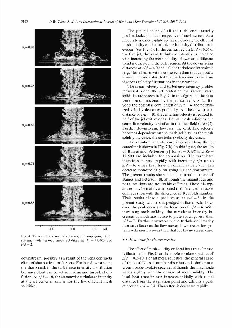
The impinging jet on a flat plate was visualized for
five mesh solidities of rs ¼ 0:00, 0.25, 0.60, 0.71 and
0.83. Fig. 4 shows typical flow images of the impinging
jet at the conditions of Re ¼ 15; 000 and z =d ¼ 2. The
smoke streaks clearly show that the vortex filaments and
the evolution of vortex formation are symmetric about
the flow axis. The toroidal vortices, which result from
an intrinsic unstability in the outer shear layer of the
impinging jet, impinge on the heated flat plate atthe lateral edge of the pipe nozzle (i.e., r =d ¼ 0:5). The
convecting wall eddies induced by the interaction be-
tween the large-scale toroidal vortices and the impinge-
ment surface are seen in the region 0:96 r =d 6 1:6. These
eddies seem to be responsible for the additional
enhancement of the local heat transfer rate in that re-
gion.
The flow structure in the central region of the jet flow
is almost the same for all mesh solidities, because the
impingement plate is placed within the potential core. In
contrast, the outer shear layer of the jet easily loses
momentum and becomes highly turbulent. The flow
patterns in Fig. 4 reveal that the axial distance beyond
which the impinging jet becomes unstable is closely re-
lated to the mesh solidity. The larger the mesh solidity,
the shorter the critical distance becomes. For mesh
screens of larger solidity, the entrainment of ambient
fluid into the jet is enhanced, changing the jet flow
characteristics [13]. Additionally, increase of the mesh
solidity leads to increases in the vortex spacing between
consecutive vortices in the downstream direction and the
size of the toroidal vortices.
3.2. Flow structure
To understand the flow structure of the impinging jet,
the streamwise mean velocity (U ) and turbulence
intensity of the streamwise velocity component of the
free jet (i.e., the component along the Z axis) were
measured. Since the impingement plate was removed for
the hot-wire measurements, the nozzle-to-plate spacing
indicates the distance between the nozzle exit and the tip
of hot-wire probe.
The mean velocity distributions at six downstream
locations for five mesh solidities are compared in Fig. 5.
At the downstream location of z =d ¼ 0:2, the mean
velocity is approximately constant in the central region
Fig. 2. Schematic diagram of (a) jet nozzle and (b) imping-
ingment plate.
2100 D.W. Zhou, S.-J. Lee / International Journal of Heat and Mass Transfer 47 (2004) 2097–2108

7/31/2019 Heat Transfer Enhancement of Impinging Jets
http://slidepdf.com/reader/full/heat-transfer-enhancement-of-impinging-jets 5/12
of the jet, irrespectively of the mesh solidity. The mean
velocity decreases rapidly at r =d ¼ 0:45 – 0:5. On moving
downstream, however, the central region of constant
mean velocity is gradually reduced and disappears at
z =d ¼ 4:0. Thereafter, the mean velocity has a bell-
shaped distribution. With going downstream, the max-
imum velocity at the jet center decreases and the jet
width expands. The effect of increasing mesh solidity
manifests as an increase in the shear layer velocity gra-
dient. As the flow goes downstream, the difference in
axial mean velocity is reduced for various mesh solidity.
At z =d ¼ 10:0, the mean velocity distribution is almost
identical for the five mesh solidities. This can be pri-
marily attributed to the self-preserving flow character-
istics of the turbulent jet due to loss of jet momentum
and active mixing with entrained ambient fluid.
The radial profiles of the axial turbulence intensity
corresponding to the mean velocity rofiles of Fig. 5 are
depicted in Fig. 6. For z =d ¼ 0:2, the turbulence inten-
sity has a sharp peak at approximately r =d ¼ 0:47.However, irrespective of the mesh solidity, the turbu-
lence intensity is small (less than 1%) at the center of
the jet. As the jet develops with going downstream, the
turbulence intensity increases in the impingement re-
gion. This increase in turbulence intensity continues up
to the downstream location of z =d ¼ 6, indicating that
the jet flow has been, somewhat, fully developed. On
going further downstream, the turbulence intensity de-
creases gradually. The turbulence intensity has its
maximum value at the location of z =d ¼ 2 and
r =d ¼ 0:45. The radial location of maximum turbulence
intensity moves slightly toward the jet center with going
Jet Nozzle
CylindricalLens
Delay GeneratorHP6555A
DC Power Supply Trigger
Digital Camera
(Olympus C-3030)
Laser Light
Sheet Pulsed Nd-Yag
Laser
Transparent
Window NichromeWire ( 100 m) µ φ
Fig. 3. Experimental set-up for smoke-wire flow visualization.
Table 1
Uncertainty analysis for local Nusselt numbers
Individual measured value d xi Nu
o Nuo xi
 100ð%Þ
xi Unit
f – 2.08–2.52
T w °C 1.43–2.32
V V 0.65–1.12
I A 0.44–1.20
qc W/m2 0.18–2.11
T a °C 0.01–0.15
T j °C 0.01–0.13
A m2 0.08k W/m K 0.06
Total uncertainty: d Nu Nu
¼ 2:84 – 3:72 (%)
D.W. Zhou, S.-J. Lee / International Journal of Heat and Mass Transfer 47 (2004) 2097–2108 2101
7/31/2019 Heat Transfer Enhancement of Impinging Jets
http://slidepdf.com/reader/full/heat-transfer-enhancement-of-impinging-jets 6/12
downstream, possibly as a result of the vena contracta
effect of sharp-edged orifice jets. Further downstream,
the sharp peak in the turbulence intensity distribution
becomes blunt due to active mixing and turbulent dif-
fusion. At z =d ¼ 10, the streamwise turbulence intensity
at the jet center is similar for the five different mesh
solidities.
The general shape of all the turbulence intensity
profiles looks similar, irrespective of mesh screen. At a
moderate nozzle-to-plate spacing, however, the effect of
mesh solidity on the turbulence intensity distribution is
evident (see Fig. 6). In the central region (r =d < 0:5) of
the free jet, the axial turbulence intensity is increased
with increasing the mesh solidity. However, a differenttrend is observed in the outer region. At the downstream
distances of z =d ¼ 4:0 and 6.0, the turbulence intensity is
larger for all cases with mesh screens than that without a
screen. This indicates that the mesh screens cause more
vigorous velocity fluctuations in the near field.
The mean velocity and turbulence intensity profiles
measured along the jet centerline for various mesh
solidities are shown in Fig. 7. In this figure, all the data
were non-dimensioned by the jet exit velocity U e. Be-
yond the potential core length of z =d ¼ 4, the normal-
ized velocity decreases gradually. At the downstream
distance of z =d ¼ 10, the centerline velocity is reduced tohalf of the jet exit velocity. For all mesh solidities, the
centerline velocity is similar in the near field ( z =d 6 2).
Further downstream, however, the centerline velocity
becomes dependent on the mesh solidity: as the mesh
solidity increases, the centerline velocity decreases.
The variation in turbulence intensity along the jet
centerline is shown in Fig. 7(b). In this figure, the results
of Baines and Perterson [8] for rs ¼ 0:438 and Re ¼12; 500 are included for comparison. The turbulence
intensities increase rapidly with increasing z =d up to
z =d ¼ 6, where they have maximum values, and then
decrease monotonically on going further downstream.
The present results show a similar trend to those of
Baines and Peterson [8], although the magnitudes and
peak locations are noticeably different. These discrep-
ancies may be mainly attributed to differences in nozzle
configuration with the difference in Reynolds number.
Their results show a peak value at z =d ¼ 8. In the
present study with a sharp-edged orifice nozzle, how-
ever, the peak occurs at the location of z =d ¼ 6. With
increasing mesh solidity, the turbulence intensity in-
creases at moderate nozzle-to-plate spacings less than
z =d ¼ 7. Further downstream, the turbulence intensity
decreases faster as the flow moves downstream for sys-
tems with mesh screens than that for the no screen case.
3.3. Heat transfer characteristics
The effect of mesh solidity on local heat transfer rate
is illustrated in Fig. 8 for the nozzle-to-plate spacings of
z =d ¼ 0:2 – 10. For all mesh solidities, the general shape
of the local Nusselt number distribution is similar at a
given nozzle-to-plate spacing, although the magnitude
varies slightly with the change of mesh solidity. The
local heat transfer rate increases initially with radial
distance from the stagnation point and exhibits a peak
at around r =d ¼ 0:4. Thereafter, it decreases rapidly.
Fig. 4. Typical flow visualization images of impinging jet for
systems with various mesh solidities at Re ¼ 15; 000 and
z =d ¼ 2.
2102 D.W. Zhou, S.-J. Lee / International Journal of Heat and Mass Transfer 47 (2004) 2097–2108

7/31/2019 Heat Transfer Enhancement of Impinging Jets
http://slidepdf.com/reader/full/heat-transfer-enhancement-of-impinging-jets 7/12
The local heat transfer rates in the radial direction
increase with mesh solidity and nozzle-to-plate spacing
tested in this study except for the case of z =d ¼ 0:2. This
increase seems to be caused by a noticeable elevation in
the turbulence intensity of the impinging jet due to the
presence of the mesh screen in the approaching stream
and jet diffusion with going downstream. The initial
enhancement of the local heat transfer rate at z =d ¼ 0:2results from the higher impingement velocity at this
downstream distance. Lytle and Webb [14] also ob-served significantly higher radial velocities near the
nozzle exit (at z =d ¼ 0:1), reaching magnitudes more
than double the jet exit velocity.
The local Nusselt number distributions show mod-
erate variation in the radial location of 0:96 r =d 6 1:6.
This is in accordance with the location of convecting
wall eddies over the impingement surface shown in Fig.
4. For smaller nozzle-to-plate spacings ( z =d 6 4), the
local Nusselt number distribution has a second peak at
around r =d ¼ 1:53. On going further downstream
( z =d > 4), this second peak disappears and the local
Nusselt number decreases monotonically beyond the
first peak. In this downstream region, the convective
heat transfer rate decreases with increasing mesh solidity
and nozzle-to-plate spacing. Pan et al. [15] reported
similar results for a turbulent liquid jet.
For comparison purposes, Fig. 8 also shows the re-
sults of Gardon and Akfirat [4] recorded at z =d ¼ 2 for a
contoured nozzle. The contoured jet shows two peaks at
radial locations similar to those observed in the present
work, although overall the Nu magnitude is much less
than that in the present results. In fact, irrespective of mesh screen solidity, the heat transfer rate in the
impingement region for a sharp-edged orifice jet is about
25% greater than that obtained previously using a con-
toured nozzle jet. This heat transfer enhancement can be
primarily attributed to the larger velocity gradient and
higher turbulence intensity of sharp-edged orifice jets.
With increasing mesh solidity, the heat transfer
enhancement increases from 24% to 27%.
The local Nusselt number values at the stagnation
point, the first peak, and the second peak vary with
changes in the nozzle-to-plate spacing and mesh solidity.
For all nozzle-to-plate spacings, the local heat transfer
0 5 10
0.0
0.5
1.0
1.5
2.0
2.5
3.0
σ
σ
s= 0.00
s= 0.25
σ
s
= 0.60
σ
σ
s= 0.71
s = 0.83
r / d
U (m/s)
z/d=10.0z/d=6.0z/d=4.0z/d=2.0z/d=1.0z/d=0.2
Fig. 5. Streamwise mean velocity profiles for five mesh solidities.
0 10 200.0
0.5
1.0
1.5
2.0
2.5
3.0
σs= 0.00
σs = 0.25
σs = 0.60
σs = 0.71
σs= 0.83
r / d
z/d=10.0z/d=6.0z/d=4.0z/d=2.0z/d=1.0z/d=0.2
eU
u2'
Fig. 6. Variation of turbulence intensity profile with respective to mesh solidity.
D.W. Zhou, S.-J. Lee / International Journal of Heat and Mass Transfer 47 (2004) 2097–2108 2103

7/31/2019 Heat Transfer Enhancement of Impinging Jets
http://slidepdf.com/reader/full/heat-transfer-enhancement-of-impinging-jets 8/12
rate at the first peak is approximately 4–8% higher than
that at the stagnation point. This coincides with the
previous results of Pan et al. [15] and Lee and Lee [2].
The magnitude and presence of the secondary peak are
largely dependent upon the nozzle-to-plate spacing.
Contrary to the case of the first peak, the ratio of the
local heat transfer rate at the second peak to the stag-
nation point value tends to decrease with increasing
axial distance from the nozzle exit.
The pressure gradient usually serves to stabilize the
laminar boundary layer in the impingement region, de-
spite the high turbulence levels in the free jet stream.
Zhou et al. [16] examined the pressure gradient distri-
bution along the impingement plate and confirmed that
0 2 4 6 8 10
0.4
0.5
0.6
0.7
0.8
0.9
1.0
σs= 0.00
σs= 0.25
σs= 0.60
σs= 0.71
σs= 0.83
U c
/ U e
z/d
0 2 4 6 8 10
0
2
4
6
8
10
12
14
12
6
0
42
36
24
30
18
Baines and Peterson [6]
σs= 0.438
Re = 12500
σs= 0.00
σs= 0.25
σs= 0.60
σs= 0.71
σs= 0.83
z/d
eU
u2'
(a)
(b)
Fig. 7. (a) Mean velocity and (b) turbulence intensity distributions along the jet centerline.
2104 D.W. Zhou, S.-J. Lee / International Journal of Heat and Mass Transfer 47 (2004) 2097–2108

7/31/2019 Heat Transfer Enhancement of Impinging Jets
http://slidepdf.com/reader/full/heat-transfer-enhancement-of-impinging-jets 9/12
the transition from laminar to turbulent boundary layerflow was triggered by the disappearance of the pressure
gradient in the spreading wall jet. The locations of the
second peak in local heat transfer rate distribution
coincide with that of induced toroidal vortices shown in
Fig. 4, indicating transport of high turbulent energy
there. The ring-shaped toroidal vortices formed on the
impingement surface generate a separating boundary
between the stagnation region and the wall jet, increas-
ing the local heat transfer coefficients at the secondary
peak location.
The presence of a mesh screen with larger solidity
seems to reduce the discrepancy of the pressure gradient
along the impingement plate, leading to a flattening of
the heat transfer distribution around the second peak for
large mesh solidities. Compared with the contoured
nozzle results of Gardon and Akfirat [4], the second
peak obtained using the sharp-edged orifice nozzle is
located slightly upstream due to faster velocity decay in
the radial direction. At downstream locations of
z =d ¼ 4, the second peak is not observed and the effect
of the mesh screen on the heat transfer enhancement is
the opposite of that observed at z =d < 4.
The variation of the local Nusselt number at the first
peak with respect to the nozzle-to-plate spacing is shown
in Fig. 9. For five mesh solidities tested in this study, asthe nozzle-to-plate spacing increases, the magnitude of
the first peak decreases initially up to a minimum at
z =d ¼ 0:6, and then rapidly increases up to a maximum
value at z =d ¼ 4. Beyond this peak, the heat transfer rate
decreases monotonically. This trend is the same as that
observed for the stagnation heat transfer rate, with the
exception of the downstream distance of z =d ¼ 0:2.
The mesh screen does not alter the location of max-
imum heat transfer rate. However, the effect of mesh
solidity on local heat transfer is enhanced with increas-
ing the nozzle-to-plate spacing up to the end of the
potential core ( z =d % 4). At z =d ¼ 4, the maximum heat
transfer rate for the system with a mesh solidity of rs ¼ 0:83 is about 3.92% larger than that without a
screen. It is worth noting that at z =d ¼ 5 the values of
the Nusselt number at the first peak have converged to a
single value that is independent of the mesh solidity.
However, on further increase of the nozzle-to-plate
spacing beyond z =d ¼ 5, the peak value decreases rap-
idly with increasing mesh solidity. Thus, the effect of the
mesh screen on the heat transfer enhancement is most
effective at z =d ¼ 4, around the potential core length, or
at a slightly smaller axial distance.
In the local Nusselt number distributions, the first
peak usually occurs in the vicinity of the nozzle edge,
regardless of whether the flow is laminar or turbulent.
Zhou et al. [16] found that the maximum pressure gra-
dient occurs at approximately a radial location of
r =d ¼ 0:5. This location seems to be closely related to
the inherent flow structure of the impinging submerged
air jets. The large pressure gradient accelerates the fluid
movement outward along the impingement plate,
resulting in a thin thermal boundary layer. It therein
seems to contribute to higher heat transfer rate. On the
other hand, as shown in Figs. 4 and 5, the large-scale
toroidal vortices strike at the location of the first peak in
the heat transfer rate on the impingement plate, where
the turbulence intensity has a maximum value. Thecombined effect of above two factors seems to lead to the
formation of the first peak in the local Nusselt number
distribution. Since these two factors are only related to
the nozzle exit configuration, the radial location of the
first peak remains almost independent of the mesh
solidity and nozzle-to-plate spacing.
Fig. 10 shows the variation of the average Nusselt
number with respect to mesh solidity (rs). Irrespective of
mesh solidity, the average Nusselt number increases
noticeably with increasing nozzle-to-plate spacing up to
a downstream location of z =d ¼ 2, after which it
monotonically decreases. When the nozzle-to-plate
(c) z/d= 2.0(a) z/d= 0.2 (b) z/d= 1.0 (d) z/d= 4.0 (e) z/d= 6.0 (f) z/d= 10.0
0 1 2 3 445
55
65
75
85
95
105
115
125
N
u
r/d
σs= 0.00
σs= 0.25
σs= 0.60
σs= 0.71
σs= 0.83
Contoured [4]
Fig. 8. Variation of local Nusselt number with respective to nozzle-to-plate spacing for various mesh solidities.
D.W. Zhou, S.-J. Lee / International Journal of Heat and Mass Transfer 47 (2004) 2097–2108 2105

7/31/2019 Heat Transfer Enhancement of Impinging Jets
http://slidepdf.com/reader/full/heat-transfer-enhancement-of-impinging-jets 10/12
0 2 4 6 8 10
80
90
100
110
120
130
σs
= 0.00
σs
= 0.25
σs
= 0.60
σs
= 0.71
σs
= 0.83
N u
z/d
Fig. 9. Variation of local maximum Nusselt number as a function of nozzle-to-plate spacing ( z =d ) and mesh solidity (rs).
0 2 4 6 8 10
50
55
60
65
70
σs
= 0.00
σs
= 0.25
σs
= 0.60
σs
= 0.71
σs
= 0.83
z/d
Nu
Fig. 10. Average Nusselt number as a function of mesh solidity.
2106 D.W. Zhou, S.-J. Lee / International Journal of Heat and Mass Transfer 47 (2004) 2097–2108

7/31/2019 Heat Transfer Enhancement of Impinging Jets
http://slidepdf.com/reader/full/heat-transfer-enhancement-of-impinging-jets 11/12
spacing is smaller than the potential core, the average
Nusselt number increases with increasing mesh solidity.
This results from the increase of the turbulence level of
the impinging jet at larger values of the mesh solidity.
Compared to the system without a screen, the augmen-
tation ratios of the average Nusselt numbers at z =d ¼ 2
for the systems with screens of rs ¼ 0:25, 0.60, 0.71 and0.83 are 0.37%, 0.66%, 1.19% and 1.38%, respectively.
The increase in turbulence intensity caused by increasing
the mesh solidity is accompanied by a decrease in the jet
momentum in the near field and a reduction in the po-
tential core length. This lower jet momentum has mostly
decayed at downstream locations beyond z =d ¼ 4.
Consequently, the average Nusselt numbers decrease
with increasing mesh solidity and nozzle-to-plate spac-
ing. The inclusion into the system of the screen of
rs ¼ 0:71 reduces the average heat transfer rate at
z =d ¼ 10 by about 5.62%. Thus, it can be concluded that
the mesh screen effectively enhances heat transfer onlywhen the nozzle-to-plate spacing is smaller than the
potential core. For z =d > 4, on the contrary, the instal-
lation of a mesh screen leads to a decrease in the heat
transfer rate.
4. Conclusions
The effect of installing a mesh screen upstream of the
jet nozzle on the impinging jet heat transfer was inves-
tigated experimentally at a fixed jet Reynolds number of
Re ¼ 15; 000 with varying the mesh solidity rs and the
nozzle-to-plate spacing z =d . Visualized flows of the
impinging jets clearly revealed the vortex structures on
the impingement plate. The location of the vortex eddy
coincided exactly with the peak in the local Nusselt
number distribution. Flow structure measurements
using a hot-wire anemometry showed that the turbu-
lence intensity increases with increasing mesh solidity
(rs) and has a maximum value at the radial location
r =d ¼ 0:47. The local heat transfer rate was highest at
around r =d ¼ 0:4. The local Nusselt numbers at the first
peak were about 4–8% larger than that at the stagnation
point, irrespective of the nozzle-to-plate spacing and
mesh solidity.The presence of the mesh screen moderately en-
hanced the heat transfer rate in the impingement region
for nozzle-to-plate spacings of z =d 6 4. This enhance-
ment is attributed to the fact that the mesh screens
modify the flow structure such that the turbulence
intensity of the impinging jet is increased within the
potential core. The local and average heat transfer rates
increased with mesh solidity and nozzle-to-plate spacing,
displaying local maximum values at z =d ¼ 4:0 and 2.0,
respectively. Among the five mesh screens tested in this
study, the screen of solidity rs ¼ 0:83 increased the local
maximum heat transfer rate about 3.92% at z =d ¼ 4:0
and the average Nusselt number was enhanced about
1.38% at z =d ¼ 2:0, compared with those for the case of
no screen. However, as the mesh screen increases the
turbulence intensity at the expense of jet momentum, the
heat transfer rate is reduced at further downstream
locations ( z =d > 4:0).
Acknowledgements
This work was supported by a NRL (National Re-
search Laboratory) project sponsored by the Ministry of
Science and Technology (MOST) of Korea.
References
[1] J.H. Lee, S.J. Lee, The effect of nozzle aspect ratio onstagnation region heat transfer characteristics of elliptic
impinging jet, Int. J. Heat Mass Transfer 43 (3) (2000) 555–
575.
[2] J.H. Lee, S.J. Lee, The effect of nozzle configuration on
stagnation region heat transfer enhancement of axisym-
metric jet impingement, Int. J. Heat Mass Transfer 43 (23)
(2000) 3497–3509.
[3] Z.Y. Guo, D.Y. Li, B.X. Wang, A novel concept for
convective heat transfer enhancement, Int. J. Heat Mass
Transfer 41 (16) (1998) 2221–2225.
[4] R. Gardon, J.C. Akfirat, The role of turbulence in
determining the heat transfer characteristics of imping-
ing jets, Int. J. Heat Mass Transfer 8 (5) (1965) 1261–
1272.[5] C.J. Hoogendoorn, The effects of turbulence on heat
transfer at a stagnation point, Int. J. Heat Mass Transfer
20 (6) (1977) 1333–1338.
[6] D.A. Zumbrunnen, M. Aziz, Convective heat transfer
enhancement due to intermittency in an impinging jet,
J. Heat Transfer 115 (1993) 91–98.
[7] H. Al-Salam et al., Effect of turbulence on heat transfer in
stagnation flow, J. Thermophys. Heat Transfer 10 (2)
(1996) 290–296.
[8] W.D. Baines, E.G. Peterson, An investigation of flow
through screens, J. Fluid Mech. 73 (2) (1951) 467–480.
[9] E.M. Laws, J.L. Livesey, Flow through screens, Ann. Rev.
Fluid Mech. 10 (2) (1978) 247–266.
[10] J. Tan-Atichat, H.M. Nagib, Interaction of free-stream
turbulence with screens and grids: a balance between
turbulence scales, J. Fluid Mech. 114 (3) (1982) 501–528.
[11] J. Groth, A.V. Johansson, Turbulence reduction by
screens, J. Fluid Mech. 197 (1) (1988) 139–155.
[12] S.J. Kline, F.A. McClintock, Describing uncertainties
in single-sample experiments, Mech. Eng. 75 (1) (1953)
3–8.
[13] C.O. Popiel, O. Trass, Visualization of a free an imping-
ing round jet, Exp. Thermal Fluid Sci. 4 (2) (1991) 253–
264.
[14] D. Lytle, B.W. Webb, Air jet impingement heat transfer
at low nozzle-to-plate spacing, Int. J. Heat Mass Transfer
37 (7) (1994) 1687–1697.
D.W. Zhou, S.-J. Lee / International Journal of Heat and Mass Transfer 47 (2004) 2097–2108 2107

7/31/2019 Heat Transfer Enhancement of Impinging Jets
http://slidepdf.com/reader/full/heat-transfer-enhancement-of-impinging-jets 12/12
[15] Y. Pan, J. Stevens, B.W. Webb, Effect of nozzle configu-
ration on transport in the stagnation zone of axisymmetric
impinging free surface liquid jets: Part II. Local heat
transfer, J. Heat Transfer 114 (3) (1992) 880–886.
[16] D.W. Zhou, C.F. Ma, M. Qin, Effect of pressure gradient
on heat transfer of impinging submerged circular jets,
J. Thermal Sci. 11 (2) (2002) 180–185.
2108 D.W. Zhou, S.-J. Lee / International Journal of Heat and Mass Transfer 47 (2004) 2097–2108