heat transfer and heat exchangers b which are
TRANSCRIPT

8 HEAT TRANSFER AND HEAT EXCHANGERS
asic concepts of heat transfer are reviewed in this chapter and applied primarily to heat exchangers, which are equipment for the transfer of heat B between two fluids through a separating wall.
Heat transfer also is a key process in other specialized
equipment, some of which are treated in the next and other chapters. The three recognized modes of heat transfer are by conduction, convection, and radiation, and may occur simultaneously in some equipment.
8.1. CONDUCTION OF HEAT
In a solid wall such as Figure 8.l(a), the variation of temperature with time and position is represented by the one-dimensional Fourier equation
For the most part, only the steady state condition will be of concern here, in which the case the partial integral of Eq. (8.1) becomes
dT dx Q = - k A - - ,
assuming the thermal conductivity k to be independent of temperature. Furthermore, when both k and A are independent of position,
AT kA Q=-kA-=-(To-TL), A r L (8.3)
in the notation of Figure 8.l(a).
situations often are cast. For example, Equation (8.3) is the basic form into which more complex
when the area is variable and
Q = WW,,, (8.5)
in certain kinds of heat exchangers with variable temperature difference.
THERMAL CONDUCTIVITY
Thermal conductivity is a fundamental property of substances that basically is obtained experimentally although some estimation methods also are available. It varies somewhat with temperature. In many heat transfer situations an average value over the prevailing temperature range often is adequate. When the variation is linear with
which demonstrates that use of a value at the average temperature gives an exact result. Thermal conductivity data at several temperatures of some metals used in heat exchangers are in Table 8.1. The order of magnitude of the temperature effect on k is illustrated in Example 8.1.
(C)
9 9
k = ko(l + a T ) ,
the integral of Eq. (8.2) becomes
(e) (0 (8 '6)
Figure 8.1. Temperature profiles in one-dimensional conduction of heat. (a) Constant cross section. (b) Hollow cylinder. (c) Composite flat wall. (d) Composite hollow cylindrical wall. (e) From fluid A to fluid F through a wall and fouhng resistance in the presence of eddies. (f) Through equivalent fluid films, fouling resistances, and Q(L/A)=kO[T,- T2+0.5&(T:- T:)]
=ko(Tl- TZ)[1+0.5a(T,+ T+)], (8.7) metal wall.
169

170 HEAT TRANSFER AND HEAT EXCHANGERS
TABLE 8.1. Thermal Conductivities of Some Metals Commonly Used in Heat Exchangers [kBtu/(hr)(sgft)W/ft)l
Temperature ("F)
Metal or Alloy -100 70 200 1000
Steels Carbon - 30.0 27.6 22.2 I Cr t MO - 19.2 19.1 18.0 41 0 - 13.0 14.4 - 304 - 9.4 10.0 13.7
13.0 316 8.1 9.4 - Monel400 11.6 12.6 13.8 22.0 Nickel 200 - 32.5 31.9 30.6 lnconel 600 - 8.6 9.1 14.3 Hastelloy C - 7.3 5.6 10.2 Aluminum - 131 133 - Titanium 11.8 11.5 10.9 12.1 Tantalum - 31.8 - - Copper 225 225 222 209 Yellow brass 56 69 Admiralty 55 64
- - - -
HOLLOW CYLINDER
As it appears on Figure 8.l(b), as the heat flows from the inside to the outside the area changes constantly. Accordingly the equivalent of Eq. (8.2) becomes, for a cylinder of length N,
dT dr Q = -kN(2zr)-,
of which the integral is
(8.9)
This may be written in the standard form of Eq. (8.4) by taking
Am = 2xLNr,, (8.10)
and
L = r 2 - r l , (8.11)
where
EXAMPLE 8.1 Conduction through a Furnace Wall
A furnace wall made of fire clay has an inside temperature of 1500°F and an outside one of 300°F. The equation of the thermal conductivity is k = 0.48[1 + 5.15(E - 4)Tl Btu/(hr)(sqft)("F/ft). Accordingly,
Q(L/A) = 0.48(1500 - 300)[1+ 5.15(E - 4)(900)] ~ 0 . 7 0 3 .
If the conductivity at 300°F had been used, Q(L/A) = 0.554.
is the logarithmic mean radius of the hollow cylinder. This concept is not particularly useful here, but logarithmic means also occur in other more important heat transfer situations.
COMPOSITE WALLS
The flow rate of heat is the same through each wall of Figure 8.l(c). In terms of the overall temperature difference,
(8.13)
where U is the overall heat transfer coefficient and is given by
(8.14)
The reciprocals in Eq. (8.14) may be interpreted as resistances to heat transfer, and so it appears that thermal resistances in series are additive.
For the composite hollow cylinder of Figure 8.l(d), with length N,
(8.15)
With an overall coefficient U, based on the inside area, for example,
2nN( Tl - T4) Q =2nNr,U,(T1 - T4) = l/U,ri '
(8.16)
On comparison of Eqs. (8.15) and (8.16), an expression for the inside overall coefficient appears to be
(8.17)
In terms of the logarithmic mean radii of the individual cylinders,
-=r i [ 1 l + l + U, kormo/(r2 - rl) kbrmb/(r3 - r2)
which is similar to Eq. (8.14) for flat walls, but includes a ratio of radii as a correction for each cylinder.
FLUID FILMS
Heat transfer between a fluid and a solid wall can be represented by conduction equations. It is assumed that the difference in temperature between fluid and wall is due entirely to a stagnant film of liquid adhering to the wall and in which the temperature profile is linear. Figure 8.l(e) is a somewhat realistic representation of a temperature profile in the transfer of heat from one fluid to another through a wall and fouling scale, whereas the more nearly ideal Figure 8.l(f) concentrates the temperature drops in stagnant fluid and fouling films.
Since the film thicknesses are not definite quantities, they are best combined with the conductivities into single coefficients
h = k/L (8.18)
so that the rate of heat transfer through the film becomes
Q = hAAT. (8.19)
Through the five resistances of Figure 8.l(f), the overall heat

8.1. CONDUCTION OF HEAT 171
EXAMPLE 8.2 Effect of Ignoring the Radius Correction of the Overall Heat Transfer Coefficient
The two film coefficients are 100 each, the two fouling coefficients are 2000 each, the tube outside diameter is 0.1 ft, wall thickness is 0.01 ft, and thermal conductivity of the metal is 30:
Basing on the inside area,
U, = [1/100 + l/2000 + [(30/0.01)(0.0448/0.04)1-] + 0.8/100 + 0.8/2000]-' = 52.0898.
ri/ro = 0.04/0.05 = 0.8, Ignoring the corrections, r, = (0.05 - 0.04)/ln 1.25 = 0.0448,
Uo = [1/100(0.8) + 1/2000(0.8) + 1/(30/0.01)(0.8963) rm/ro = 0.8963, U = (2/100 + 2/2000 + 1/30/0.01)-' = 46.8750.
+ 1/100 + 1/2000]-' = 41.6721. The last value is very nearly the average of the other two.
transfer coefficient is given by
(8.20)
where L , is the thickness of the metal.
overall heat transfer coefficient based on the outside surface is If the wall is that of hollow cylinder with radii r, and r,, the
where r,,, is the mean radius of the cylinder, given by Eq. (8.12). Since wall thicknesses of heat exchangers are relatively small
and the accuracy of heat transfer coefficients may not be great, the ratio of radii in Eq. (8.21) often is ignored, so that the equation for the overall coefficient becomes simply
1 1 1 1 1 1 _=- +-+- +-+- u hi hz k3lL3 h, hs
(8.22)
The results of the typical case of Example 8.2, however, indicate that the correction may be significant. A case with two films and two solid cylindrical walls is examined in Example 8.3.
EXAMPLE 8.3 A Case of a Composite Walk Optimum Insulation Thickness for a Steam Line
A 3 in. IPS Sched 40 steel line carries steam at 500°F. Ambient air is at 70°F. Steam side coefficient is 1000 and air side is 3Btu/(hr)(sqft)("F). Conductivity of the metal is 30 and that of insulation is 0.05 Btu/(hr)(sqft)("F/ft). Value of the steam is $S.OO/MBtu. cost of the insulation is $1.5/(yr)(cuft). Operation is 8760 hr/yr. The optimum diameter d of insulation thickness will be found.
Pipe: do = 0.2917 ft, d, = 0.2557 ft, In(do/di) = 0.1317.
Insulation:
In(do/di) = ln(d/0.2917). (1)
Heat transfer coefficient based on inside area:
1 0.1317+ln(d/0.2917) 1 0.05 +3d] '
U,=di __
Q/Ai = UiAT = 430U,.. [lOOOd, + 30
Steam cost:
C, = 5(10-6)(8760)Q/Ai = 0.0438Q/Aj, $ (yr)(sqft inside). (3)
3 70 F
18 ! Example 8.3. O P t i m u r n insul ation thickness
2r3 RERD D 1 .* D 2 38 DATR .2317,.2557 48 INPUT D 5 8 Ul=.BBl/DZ+. 1387/38+LOG(D./Di
j/.85+1/3/D 68 U= 1 /U 1 l D 2 78 @=4JB*U 89 C1=.8438tG! 98 CZ=1.5*(Dn2-D1*2)/D2rr2 189 C=Cl+C2 ! ( r e q ' d t o be minim
Urn j
c 118 PRINT USING 128 j DrU,Cl,C2>
1 28 I MRGE . DDD , X I . DUD , X DD . DD .. X .. D D . D D , X , D D . D D D D
172
EXAMPLE 8.S-(continued)
HEAT TRANSFER AND HEAT EXCHANGERS
2 D U c2 c1 + c ---- ,498 . 3 5 4 6.66 3.56 1r3.2147 ,494 .349 6.57 3.65 18.2118 ,495 ,347 6.S4 3 . 6 7 18 .2117-w .496 346 6 . 5 2 3.659 10 .2118 .SO8 .?I41 6 . 4 3 3.78 16.2148 Insulation cost:
C, = 1.5Kn,/A,
, $/(yr)(sqft inside). - 1.5(dZ- 0.2917’) -
(0.2557)’ (4)
Total cost:
(5) C = C , + C2+ minimum.
Substitute Eqs. (2)-(4) into Eq. (5). The outside diameter is the key unknown.
The cost curve is fairly flat, with a minimum at d = 0.50ft, corresponding to 1.25 in. thickness of insulation. Some trials are shown with the computer program. A more detailed analysis of insulation optima is made by Happel and Jordan [Chern. Process Econ., 380 (1975)], although their prices are dated. Section 8.12 also discusses insulation.
Heat transfer coefficients are empirical data and derived correlations. They are in the form of overall coefficients U for frequently occurring operations, or as individual film coefficients and fouling factors.
8.2. MEAN TEMPERATURE DIFFERENCE
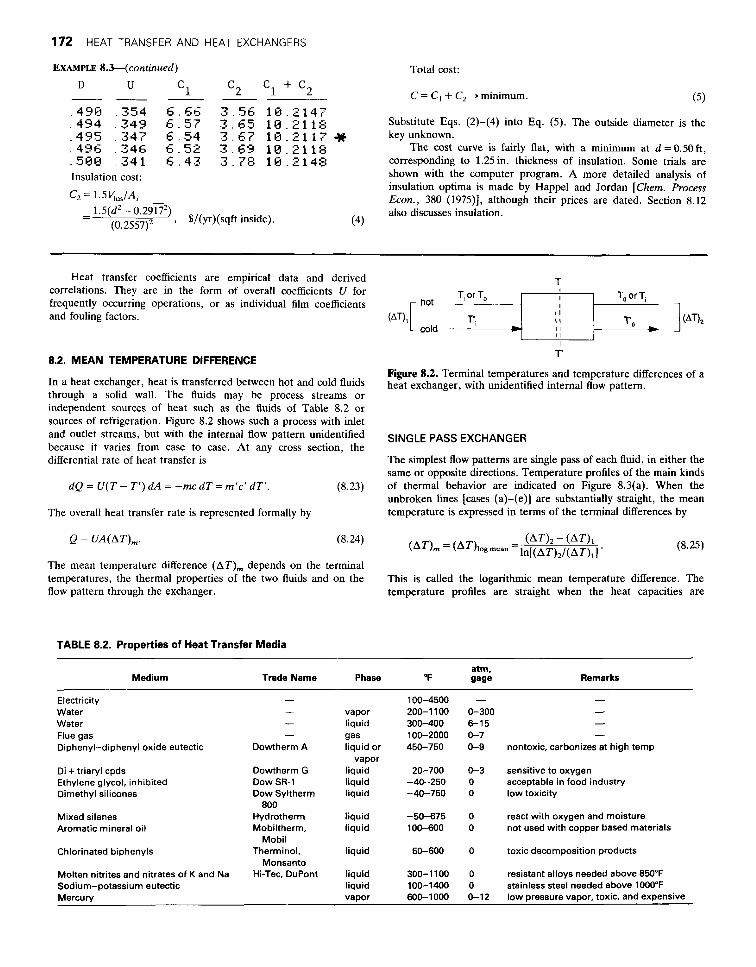
In a heat exchanger, heat is transferred between hot and cold fluids through a solid wall. The fluids may be process streams or independent sources of heat such as the fluids of Table 8.2 or sources of refrigeration. Figure 8.2 shows such a process with inlet and outlet streams, but with the internal flow pattern unidentified because it varies from case to case. At any cross section, the differential rate of heat transfer is
dQ = U(T - T’) dA = -mc d T = m’c’ dT’. (8.23)
The overall heat transfer rate is represented formally by
T
,hot -<*+ , (AT), (AT),
cold I I I I
T’
Figure 8.2. Terminal temperatures and temperature differences of a heat exchanger, with unidentified internal flow pattern.
SINGLE PASS EXCHANGER
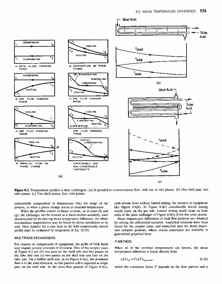
The simplest flow patterns are single pass of each fluid, in either the same or opposite directions. Temperature profiles of the main kinds of thermal behavior are indicated on Figure 8.3(a). When the unbroken lines [cases (a)-(e)] are substantially straight, the mean temperature is expressed in terms of the terminal differences by
Q = UA(AT),. (8.25) .-
The mean temperature difference (AT), depends on the terminal temperatures, the thermal properties of the two fluids and on the flow pattern through the exchanger.
This is called the logarithmic mean temperature difference. The temperature profiles are straight when the heat capacities are
TABLE 8.2. Properties of Heat Transfer Media
atm, Medium Trade Name Phase “F gage Remarks
Electricity - 100-4500 - - Water - vapor 200-1 100 0-300 - Water - liquid 300-400 6-15 -
100-2000 0-7 - gas Flue gas Diphenyl-diphenyl oxide eutectic Dowtherm A liquid or 450-750 0-9 nontoxic, carbonizes at high temp
Di + triaryl cpds Dowtherm G liquid 20-700 0-3 sensitive to oxygen Ethylene glycol, inhibited DOW SR-1 liquid -40--250 0 acceptable in food industry Dimethyl silicones
Mixed silanes Hydrotherm liquid -50-675 0 react with oxygen and moisture Aromatic mineral oil Mobiltherm, liquid 100-600 0 not used with copper based materials
Chlorinated biphenyls Therminol, liquid 50-600 0 toxic decomposition products
Molten nitrites and nitrates of K and Na Hi-Tec. DuPont liquid 300-1100 0 resistant alloys needed above 850°F Sodium-potassium eutectic liquid 100-1400 0 stainless steel needed above 1000°F Mercury vapor 600-1000 0-12 low pressure vapor, toxic, and expensive
-
vapor
Dow Syltherm liquid -40-750 0 low toxicity 800
Mobil
Monsanto
8.2. MEAN TEMPERATURE DIFFERENCE 173
r Shell fluid
CDNDENEING
01 BOTH FLUIDS CHANGING PHASE
CONDENSING 1 , - -
HEATING P I b l ONE FLUID CHANGING
PHASE
COOLING I
CI ONE fLUlD CHANGING PHASE
HEATING
6) PARALLEL F L O W , NO PHASE CHANGE
COOLING
~~
01 COUNTERFLOW , NO PHASE CHANGE
SUBCOOLING
CONDENSING
SUBCOOLING
CONDENSING
I1 ONE FLUID CHANGING PHASE
COOLING
E VAPOR AT ING HE AT ING
SUPERHEATING ~
ONE FLUID CHANGING PL1ASE
PARTIAL CONOENSATION
1 2
HE4TING
CONOE NSABLE A N 0 NON -CONDENSABLE COMPONENTS
1 I
I I I I I ' e '
I I -Tube fluid
Shell fluid 1
Tube fluid
\ - t
Figure 8.3. Temperature profiles in heat exchangers. (a) In parallel or countercurrent flow, with one or two phases. (b) One shell pass, two tube passes. (c) Two shell passes, four tube passes.
substantially independent of temperature over the range of the process, or when a phase change occurs at constant temperature.
When the profiles consist of linear sections, as in cases ( f ) and (g), the exchanger can be treated as a three-section assembly, each characterized by its own log mean temperature difference, for which intermediate temperatures may be found by direct calculation or by trial. Heat transfer for a case such as (h) with continuously curved profile must be evaluated by integration of Eq. (8.23).
MULTIPASS EXCHANGERS
For reasons of compactness of equipment, the paths of both fluids may require several reversals of direction. Two of the simpler cases of Figure 8.3 are (b) one pass on the shell side and two passes on the tube side and (c) two passes on the shell side and four on the tube side. On a baffled shell side, as on Figure 8.4(c), the dominant flow is in the axial direction, so this pattern still is regarded as single pass on the shell side. In the cross flow pattern of Figure 8.5(c),
each stream flows without lateral mixing, for instance in equipment like Figure 8.6(h). In Figure 8.6(i) considerable lateral mixing would occur on the gas side. Lateral mixing could occur on both sides of the plate exchanger of Figure 8.6(h) if the fins were absent.
Mean temperature differences in such flow patterns are obtained by solving the differential equation. Analytical solutions have been found for the simpler cases, and numerical ones for many impor- tant complex patterns, whose results sometimes are available in generalized graphical form.
F-M ETHOD
When all of the terminal temperatures are known, the mean temperature difference is found directly from
(AT), = F(AT)logmeanr (8.26)
where the correction factor F depends on the flow pattern and is

174 HEAT TRANSFER AND HEAT EXCHANGERS
Fluid A inlet
Hot Fluid Cold Fluid
Outlet Outlet
(C)
Vopor
Steam
lory les
t Condensote Liquid
outlef feed
Y Tube
supports
t Hot liquid
outlet
(4 Figure 8.4. Example of tubular heat exchangers (see also Fig. 8.14). (a) Double-pipe exchanger. (b) Scraped inner surface of a double-pipe exchanger. (c) Shell-and-tube exchanger with fixed tube sheets. (d) Kettle-type reboiler. (e) Horizontal shell side thermosiphon reboiler. ( f ) Vertical tube side thermosiphon reboiler. (g) Internal reboiler in a tower. (h) Air cooler with induced draft fan above the tube bank. (i) Air cooler with forced draft fan below the tube bank.

8.2. MEAN TEMPERATURE DIFFERENCE 175
Vapor
control
f t u --
I t ’ 1 Bottoms
(e)
t L-. a-x + Bottoms 1 Bottoms
(f) (9)
S e c t i o n - s u w t
t
fluid out-
(h)
F k r e 8.4.-(continued)
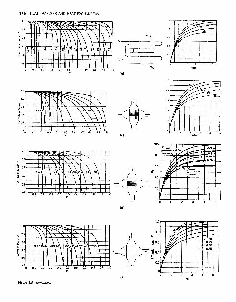
Figure 8.5. Correction factor F, effectiveness and number of transfer units in multipass and cross flow heat exchangers (Bowman et al., Trans ASME 283, 1940; Kays and London, 1984):
T on the tubeside, T’ on the shellside. i = input, o = output. (a) One pass on shellside, any multiple of two passes on tubeside. (b) Two passes on shell side, any multiple of four on tubeside. (c) Cross flow, both streams unmixed laterally. (d) Cross flow, one stream mixed laterally. (e) Cross flow, both streams mixed laterally. ( f ) Effectiveness and number of transfer units in parallel and countercurrent flows. (g) Three shell passes, multiples of six on tubeside. (h) Four shell passes, multiples of eight on tubeside. (i) Five shell passes, multiples of ten on tubeside. (j) Six shell passes, multiples of 12 on tubeside.
176 HEAT TRANSFER AND HEAT EXCHANGERS
P
P
P
P
Figure 8.5-(continued)
0 1 2 3 4 5
0 1 2 3 4 5 NTU

8.2. MEAN TEMPERATURE DIFFERENCE 177
o! ' 110 ' 210 NTU ' 310 ' 4; ' 5.;
cci
:,+ ,
1.0
0.9
2 0.8 " c I
2 0.7 e b u 0.6
0 0.1 0.2 0.3 0.4 0.5 0.6 0.7 0.8 0.9 1.0 K
(9)
1.0
0.9
t. 5 0.8 - u c - 0.7
2 E V 0.6
0.5
0 0.1 0.2 0.3 0.4 0.5 0.6 0.7 0.8 0.9 1.0 X
(i) Figure IS-(continued)
expressed in terms of these functions of the terminal temperatures:
(8.27) T - Z - actual heat transfer Ti - 7;
p="---- maximum possible heat transfer '
(8.28)
Some analytical expressions for F are shown in Table 8.3, and more graphical solutions in Figure 8.5.
0 0 1.0 20 3.0 4.0 5.0 mu
1.0
0.9
rs 0.8 ; -
c 0.7
0.6
0.5
K
(i)
This method is especially easy to apply when the terminal temperatures are all known, because then F and (AT)logmean are immediately determinable for a particular flow pattern. Then in the heat transfer equation
Q = UAF(AT),, (8.29)
any one of the quantities Q, U, or A may be found in terms of the others. A solution by trial is needed when one of the terminal temperatures is unknown, as shown in Example 8.4. The next

178 HEAT TRANSFER AND HEAT EXCHANGERS
(e) (9)
Liquid flow
(i)
Figure 8.6. Examples of extended surfaces on one or both sides. (a) Radial fins. (b) Serrated radial fins. (c) Studded surface. (d) Joint between tubesheet and low fin tube with three times bare surface. (e) External axial fins. ( f ) Internal axial fins. (9) Finned surface with internal spiral to promote turbulence. (h) Plate fins on both sides. (i) Tubes and plate fins.

8.3. HEAT TRANSFER COEFFICIENTS 179
TABLE 8.3. Formulas for Mean Temperature Difference and Effectiveness in Heat Exchangers
1. Parallel or countercurrent flow,
(AT), = (AThogmean = (AT, - AT,)/In(AT,/AT,).
2. In general,
(AT), = F(AThog,,,,
or
(AT), = 8(7;. - 71,
where f and 8 depend on the actual flow paths on the shell and tube sides and are expressed in terms of these quantities:
c = c,in/~max. P= (To - 7;.)/(7 - 6) =actual heat transfer/
R = (7;. - To)/(TA - J’) = m’c’/mc. (maximum possible heat transfer),
3. Number of transfer units, N or NTU, is
N = UA/Cmi, = P/8,
where Cmi, is the smaller of t h e two values mc or m’c’ of the products of mass rate of flow times the heat capacity.
4. In parallel flow, P = N8 = { 1 - exp[-N(l + C)1}/(1 + C). 5. In countercurrent flow, P = N8 = { 1 - expl-N(l - C)]}/{ 1 - C exp
6. One shell pass and any multiple of two tube passes, l-N(1 -CHI.
] R + 1 , 2 - P(R + 1 - G) F=- m. I n ( l - P ) / l n [
R - 1 1-PR 2 - P ( R + l + m T i ) ’
7. Two shell passes and any multiple of four tube passes,
F = [--In m -]/ 1 - P 2(R-1) 1-PR
1 2/P-1 - R + ( 2 / P ) ~ ( l - P ) ( l - P R ) + ~ 2/P - 1 - R + (2/P)Y(l - P)(1 - P R ) - rn
8. Cross flow, (a) Both streams laterally unmixed, P= 1 -exp{[exp(-NCn)- l]/Cn},
(b) Both streams mixed, P = (1/11 - exp(-N)I + C/[1 - exp(-NC)] -
(c) C,,, mixed, Cmi, unmixed, P=(l /C){l -exp[-C(1 - e-N)]}. (d) Cmi, mixed. C,,, unmixed, P = 1 - exp{-(l/C)[l -exp(-NC)]).
9. For more complicated patterns only numerical solutions have been made. Graphs of these appear in sources such as Heat Exchanger Design Handbook (HEOH. 1983) and Kavs and London (1984).
where n = N-o.22.
l/N}-’.
method to be described, however, may be more convenient in such a case.
&METHOD
One measure of the size of heat transfer equipment is the number of transfer units N defined by
N = UA/Cmin, (8.30)
where Cmin is the smaller of the two products of mass flow rate and heat capacity, mc or m’c‘. N is so named because of a loose analogy with the corresponding measure of the size of mass transfer equipment.
A useful combination of P and N is their ratio
where (To - r ) is the temperature change of the stream with the smaller value of mc. Thus 0 is a factor for obtaining the mean temperature difference by the formula:
(AT), = 0(T: - r) (8.32)
when the two inlet temperatures are known. The term P often is called the exchanger effectiveness.
Equations and graphs are in Table 8.3 and Figure 8.4. Many graphs for 8, like those of Figure 8.7, may be found in the Heat Exchanger Design Handbook (HEDH, 1983). When sufficient other data are known about a heat exchange process, an unknown outlet temperature can be found by this method directly without requiring trial calculations as with the F-method. Example 8.5 solves such a problem.
SELECTION OF SHELL-AND-TUBE NUMBERS OF PASSES
A low value of F means, of course, a large surface requirement for a given heat load. Performance is improved in such cases by using several shells in series, or by increasing the numbers of passes in the same shell. Thus, two 1-2 exchangers in series are equivalent to one large 2-4 exchanger, with two passes on the shell side and four passes on the tube side. Usually the single shell arrangement is more economical, even with the more complex internals. For economy, F usually should be greater than 0.7.
EXAMPLE
A shell side fluid i s required to go from 200 to 140°F and the tube side from 80 to 158°F. The charts of Figure 8.5 will be used:
P = (200 - 140)/(200 - 80) = 0.5, R (158 - 80)/(200 - 140) = 1.30.
For a 1-2 exchanger, F = 0.485: 2-4 0.92 4-8 0.98
The 1-2 exchanger is not acceptable, but the 2-4 is acceptable. If the tube side outlet were at 160 instead of 158, F would be zero for the 1-2 exchanger but substantially unchanged for the others.
8.3. HEAT TRANSFER COEFFICIENTS
Data are available as overall coefficients, individual film coefficients, fouling factors, and correlations of film coefficients in terms of

180 HEAT TRANSFER AND HEAT EXCHANGERS
EXAMPLE 8.4 Performance of a Heat Exchanger with the F-Method
Operation of an exchanger is represented by the sketch and the equation
Q / U A = 50 = F(AT),,
80 7
I a 100
L 120
The outlet temperature of the hot fluid is unknown and designated by T. These quantities are formulated as follows:
200- T p=- 200-80' 200 - T R = - 120 - 80 '
T - 80 - (200 - 120) (AT)''"=In[(T -80)/(200- 12O)J
F is represented by the equation of Item 6 of Table 8.3, or by Figure 8.4(a). Values of T are tried until one is found that satisfies G = 50 - F(AT),, -- 0. The printout shows that
T = 145.197
The sensitivity of the calculation is shown in the following
tabulation:
T P R (AT),, F G
145.0 0.458 1.375 72.24 0.679 0.94 145.197 0.457 1.370 72.35 0.691 0.00061 145.5 0.454 1.363 72.51 0.708 -1.34
1 9 ! Example 8 . 4 . The F-met hod
39 INPlJT T 28 SHORT P .SR,F ,T l
1.' P=(29B-T) / .12@ 50 R = ( Z B # - T j / 4 8 6 8 T l = ( T - 1 6 8 j / L O G ( { T - S B j / ~ 8 ) 78 E = C R * Z + 1 ) * . 5
38 F=F/LOG((2-Pt{R+l-E)j/~~-P*~ R + 1+E) > j
1 9 8 P R I N T " T = " ; T 1 1 0 P R I N T "G="jC 1 2 8 PRINT "P=" ;P 1 3 8 P R I N T " R = " i R 1 4 8 P R I N T " F = " j F 1 5 8 PRINT " T l = " i T l
88 F=E/(R-lltLOG({l-P),(l-P*R)~
315 G z 5 8 - F t T 1
1 6 8 GOTO 30 1 7 8 END
T= 1 4 5 . 1 9 7 G = . 9 8 2 4 8 2 8 6 P = . 4 5 6 6 9 R= 1 . 3 7 8 1 F= , 6 4 1 8 9 T l = 7 2 . 3 4 6
physical properties and operating conditions. The reliabilities of maintained in a particular plant is not certain. Sometimes fouling these classes of data increase in the order of this listing, but also the develops slowly; in other cases it develops quickly as a result of ease of use of the data diminishes in the same sequence. process upset and may level off. A high coefficient often is
desirable, but sometimes is harmful in that excessive subcooling OVERALL COEFFICIENTS may occur or film boiling may develop. The most complete list of
The range of overall heat transfer coefficients is approximately 10-200 Btu/(hr)(sqft)("F). Several compilations of data are available, notably in the Chemical Engineers Handbook (McGraw- Hill, New York, 1984, pp. 10.41-10.46) and in Ludwig (1983, pp. 70-73). Table 8.4 qualifies each listing to some extent, with respect to the kind of heat transfer, the kind of equipment, kind of process stream, and temperature range. Even so, the range of values of U usually is two- to three-fold, and consequently only a rough measure of equipment size can be obtained in many cases with such data. Ranges of the coefficients in various kinds of equipment are compared in Table 8.5.
FOULING FACTORS
Heat transfer may be degraded in time by corrosion, deposits of reaction products, organic growths, etc. These effects are accounted for quantitatively by fouling resistances, l/hP They are listed separately in Tables 8.4 and 8.6, but the listed values of coefficients include these resistances. For instance, with a clean surface the first listed value of U in Table 8.4 would correspond to a clean value of U = 1/(1/12-0.04)=23.1. How long a clean value could be
fouling factors with some degree of general acceptance is in the TEMA (1978) standards. The applicability of these data to any particular situation, however, is questionable and the values probably not better than +SO%. Moreover, the magnitudes and uncertainties of arbitrary fouling factors may take the edge off the importance of precise calculations of heat transfer coefficients. A brief discussion of fouling is by Walker (1982). A symposium on this important topic is edited by Somerscales and Knudsen (1981).
INDIVIDUAL FILM COEFFICIENTS
Combining individual film coefficients into an overall coefficient of heat transfer allows taking into account a greater variety and range of conditions, and should provide a better estimate. Such individual coefficients are listed in Tables 8.6 and 8.7. The first of these is a very cautious compilation with a value range of 1.5- to 2-fold. Values of the fouling factors are included in the coefficient listings of both tables but are not identified in Table 8.7. For clean service, for example, involving sensible heat transfer from a medium organic to heating a heavy organic,
U = 10,000/(57 - 16 + 50 - 34) = 175

8.3. HEAT TRANSFER COEFFICIENTS 181
5
- - E. 5
E r - 2. 5
3.0 I- - 8.4 +
0
(b)
Figure 8.7. 0 correction charts for mean temperature difference: (a) One shell pass and any multiple of two tube passes. (b) Two shell passes and any multiple of four tube passes. [ (HEDH, 1983); afier Mueller in Rohsenow and Hartnett, Handbook of Heat Transfer, Section 18, McGraw-Hill, New York, 1973. Other cases also are covered in these references.]
-; 8.5 2. 8
E ? a 4 2. 5 A- - 3.0 t=.

182 HEAT TRANSFER AND HEAT EXCHANGERS
EXAMPLE 8.5 Application of the Effectiveness and the 8 Method
Operating data of an exchanger are shown on the sketch. These data include
V A = 2000, m'c' = 10o0, mc = 800,
C = Cmin/Cmax = 0.8.
m'c' = 1000
UA = 2000
T;
The equation for effectiveness P is given by item 6 of Table 8.3 or it can be read off Figure 8.4(a). Both P and 0 also can be read off Figure 8.4(a) at known N and R = CJC, = 0.8. The number of
transfer units is
N = UA/Cmin = 2000/800 = 2.5, c= C,,/C,, = 0.8, D = = 1.2806,
P = = 0.6271, 2
1 + C + D[1+ exp(-ND)]/l - exp(-ND) e = P/N = 0.2508,
AT, = e(200 - 80) = 30.1, Q = UA(AT), = 2000(30.1) = 60,200,
= 800(200 - &) = 1000(T; - 80), :. & = 124.75, Ti = 140.2.
also may be found from the definition of P:
actual AT 200 - T2 = o.6271, P = =-
max possible AT 200 - 80 :. T2 = 124.78.
With this method, unknown terminal temperatures are found without trial calculations.
compared with a normal value of
V = 10,000/(57 + 50) = 93,
where the averages of the listed numbers in Table 8.6 are taken in each case.
METAL WALL RESISTANCE
With the usual materials of construction of heat transfer surfaces, the magnitudes of their thermal resistances may be comparable with the other prevailing resistances. For example, heat exchanger tubing of 1/16in. wall thickness has these values of l/h, = L / k for several common materials:
Carbon steel l / h , = 1.76 x Stainless steel 5.54 x 1 0 - ~ Aluminum 0.40 x 1 0 - ~ Glass 79.0 x 1 0 - ~
which are in the range of the given film and fouling resistances, and should not be neglected in evaluating the overall coefficient. For example, with the data of this list a coefficient of 93 with carbon steel tubing is reduced to 88.9 when stainless steel tubing is substituted.
DIMENSIONLESS GROUPS
The effects of the many variables that bear on the magnitudes of individual heat transfer coefficients are represented most logically and compactly in terms of dimensionless groups. The ones most pertinent to heat transfer are listed in Table 8.8. Some groups have ready physical interpretations that may assist in selecting the ones appropriate to particular heat transfer processes. Such interpreta- tions are discussed for example by Grober et al. (1961, pp. 193-198). A few are given here.
The Reynolds number, Dup/p = pu2/(pu/D), is a measure of the ratio of inertial to viscous forces.
The Nusselt number, hL/k = h / ( k / L ) , is the ratio of effective heat transfer to that which would take place by conduction through a film of thickness L.
The Peclet number, DGC/k = G C / ( k / D ) and its modification, the Graetz number wC/kL, are ratios of sensible heat change of the flowing fluid to the rate of heat conduction through a film of thickness D or L.
The Prandtl number, C p / k = ( p / p ) / ( k / p C ) , compares the rate of momentum transfer through friction to the thermal diffusivity or the transport of heat by conduction.
The Grashof number is interpreted as the ratio of the product of the buoyancy and inertial forces to the square of the viscous forces.
The Stanton number is a ratio of the temperature change of a fluid to the temperature drop between fluid and wall. Also, St = (Nu)/(Re)(Pr).
An analogy exists between the transfers of heat and mass in moving fluids, such that correlations of heat transfer involving the Prandtl number are valid for mass transfer when the Prandtl number C p / k is replaced by the Schmidt number p / p k , . This is of particular value in correlating heat transfer from small particles to fluids where particle temperatures are hard to measure but measurement of mass transfer may be feasible, for example, in vaporization of naphthalene.
8.4. DATA OF HEAT TRANSFER COEFFICIENTS
Specific correlations of individual film coefficients necessarily are restricted in scope. Among the distinctions that are made are those of geometry, whether inside or outside of tubes for instance, or the shapes of the heat transfer surfaces; free or forced convection; laminar or turbulent flow; liquids, gases, liquid metals, non- Newtonian fluids; pure substances or mixtures; completely or partially condensable; air, water, refrigerants, or other specific substances; fluidized or fixed particles; combined convection and radiation; and others. In spite of such qualifications, it should be

8.4. DATA O
F HEAT TR
ANSFER
CO
EFFICIEN
TS 183
fl
?
IIYYIIYIYI 9
71
I u! 0
N
JI
I
?
IYI I
ll
Il
l
13x1
555 0
00
u
)u
)u
)
ccc
L
c
m
Il
l1
>>
>I
YY
YS
.- 6 .p .p ,p ?!?!?!?! L
LL
L
rr
rr

184 H
EAT TRAN
SFER A
ND
HEAT EXC
HAN
GER
S
33
3
YYIIIYIIIIXII I
u 8 U m D
- .E
c
f"
s >
z8
0
m C
m
u 5
z
3 I13
I
& c
3
Y
C
e 'c b P
>
W
3
n
7 3 II 3
0
3
n

8.4. DATA OF HEAT TRANSFER COEFFICIENTS 185
TABLE 8.5. Ranges of Overall Heat Transfer Coefficients in Various Types of Exchangers [U Btu/(hr)(sqft)("F)]"
Equipment Process U
Shell-and-tube exchanger [Fig. 8.4k)l
Double-pipe exchanger [Fig. 8.4(a)l
Irrigated tube bank
Plate exchanger [Fig. 8.8(a)l
Spiral exchanger [Fig. 8.8(c)l
Compact [Fig. 8.6(h)l
Stirred tank, jacketed
Stirred tank, coil inside
gas (1 atml-gas (1 atm) gas (250 atm)-gas (250 atm) liquid-gas (1 atm) liquid-gas (250 atm) liquid-liquid liquid-condensing vapor
gas (1 atm)-gas (1 atm) gas (250 atm)-gas (250 atm) liquid-gas (250 atm) liquid-liquid
water-gas (1 atm) water-gas (250 atm) water-liquid water-condensing vapor
water-gas (1 atm) water-liquid
liquid-liquid liquid-condensing steam
gas (1 atm)-gas (1 atm) gas (1 atm)-liquid
liquid-condensing steam boiling liquid-condensing steam water-liquid
liquid-condensing steam
1-6 25-50 2-12
35-70 25-200 50-200
2-6 25-90 35- 1 00 50-250
3-10 25-60 50-1 60 50-200
3-10 60-200
120-440 160-600
2-6 3-10
90-260 120-300 25-60
120-440 water-liquid ~.
Btu/(hr)(sqft)("F) = 5.6745 W/m2 K. Data from (HEDH, 1983).
borne in mind that very few proposed correlations are more accurate than f20% or so.
Along with rate of heat transfer, the economics of practical exchanger design requires that pumping costs for overcoming friction be taken into account.
DIRECT CONTACT OF HOT AND COLD STREAMS
Transfer of heat by direct contact is accomplished in spray towers, in towers with a multiplicity of segmented baffles or plates (called shower decks), and in a variety of packed towers. In some processes heat and mass transfer occur simultaneously between phases; for example, in water cooling towers, in gas quenching with water, and in spray or rotary dryers. Quenching of pyrolysis gases in transfer lines or towers and contacting on some trays in fractionators may involve primarily heat transfer. One or the other, heat or mass transfer, may be the dominant process in particular cases.
Data of direct contact heat transfer are not abundant. The literature has been reviewed by Fair (1972) from whom specific data will be cited.
One rational measure of a heat exchange process is the number of transfer units. In terms of gas temperatures this is defined by
(8.33)
The logarithmic mean temperature difference usually is applicable. For example, if the gas goes from 1200 to 150°F and the liquid countercurrently from 120 to 4WF, the mean temperature
Ng = T,.in - T,.out
( T p - TL)mean '
90-210
difference is 234.5 and Ng = 4.48. The height of a contact zone then is obtained as the product of the number of transfer units and the height H, of a transfer unit. Several correlations have been made of the latter quantity, for example, by Cornell, Knapp, and Fair (1960) and modified in the Chemical Engineers Handbook (1973, pp. 18.33, 18.37). A table by McAdams (1954, p. 361) shows that in spray towers the range of H, may be 2.5-10 ft and in various kinds of packed towers, 0.4-4 ft or so.
Heat transfer coefficients also have been measured on a volumetric or cross section basis. In heavy hydrocarbon fraction- ators, Neeld and O'Bara (1970) found overall coefficients of 1360- 3480 Btu/(hr)(OF)(sqft of tower cross section). Much higher values have been found in less viscous systems.
Data on small packed columns were correlated by Fair (1972) in the form
Ua = CG"L", Btu/(hr)(cuft)("F), (8.34)
where the constants depend on the kind of packing and the natures of the fluids. For example, with air-oil, 1 in. Raschig rings, in an 8in. column
Ua = 0.083G0.94L0.2s. (8.35)
When G and L are both 5000 lb/(hr)(sqft), for instance, this formula gives Ua = 2093 Btu/(hr)(cuft)("F).
In spray towers, one correlation by Fair (1972) is
h,a = 0.043G0.8L0.4/Z0.5 Btu/(hr)(cuft)("F). (8.36)

186 HEAT TRANSFER AND HEAT EXCHANGERS
TABLE 8.6. Typical Ranges of Individual Film and Fouling Coefficients [h Btu/(hr)(sqft)("F)]
Fluid and Process Conditions P (atm) (AT),,,,, ("F) i o 4 h io4 I+
Sensible Water Ammonia Light organics Medium organics Heavy organics Heavy organics Very heavy organics Very heavy organics Gas Gas Gas
Condensing transfer Steam ammonia Steam ammonia Steam ammonia Steam ammonia Steam ammonia Light organics Light organics Light organics Medium organics Heavy organics Light condensable mixes Medium condensable mixes Heavy condensable mixes
Vaporizing transfer Water Water Ammonia Light organics Light organics Medium organics Medium organics Heavy organics Heavy organics Verv heavv oraanics
liquid liquid liquid liquid liquid heating liquid cooling liquid heating liquid cooling
all condensable 1 % noncondensable 4% noncondensable all condensable all condensable pure 4% noncondensable pure narrow range narrow range narrow range narrow range medium range
pure narrow range pure narrow range pure narrow range
1-2 10
100
0.1 0.1 0.1 1
10 0.1 0.1
10 1 1 1 1 1
<5 <loo <30
20 20 20 20 20 20
45 36 36 36 27 36 27 36 27
7.6-1 1.4 7.1-9.5 28-38 38-76 23-76
142-378 189-568 378-946 450-700 140-230 57-113
4.7-7.1 9.5-14.2 19-28
3.8-5.7 2.3-3.8 28-38 57-76 8-19
14-38 28-95 23-57 38-95 95-1 90
5.7-19 3.8-14 11-19 14-57 19-76 16-57 23-95 23-95 38-142
narrow ranae 20 27 57-189
6-14 0-6 6-11 9-23
1 1 -57 11-57 23-1 70 23- 1 70 0-6 0-6 0-6
0-6 0-6 0-6 0-6 0-6 0-6 0-6 0-6 6-30
11-28 0-1 1 6-23
11-45
6-12 6-12 6-12 6-12 6-17 6-17 6-17
11-28 11-45 11-57 , . , I
Light organics have viscosity <1 cP, typically similar to octane and lighter hydrocarbons. Medium organics have viscosities in the range 1-5cP. like kerosene, hot gas oil, light crudes, etc. Heavy organics have viscosities in the range 5-100 cP, cold gas oil, lube oils, heavy and reduced crudes, etc. Very heavy organics have viscosities above 100 cP, asphalts, molten polymers, greases, etc. Gases are all noncondensables except hydrogen and helium which have higher coefficients. Conversion factor: 1 Btu/(hr)(sqft)("F) = 5.6745 W/m2 K. (After HEDH, 1983, 3.1.4-4).
In a tower with height Z=3Oft and with both G and L at 5000 Ib/(hr)(cuft), for example, this formula gives h,a = 215.
In liquid-liquid contacting towers, data cited by Fair (1972) range from 100-12,000 Btu/(hr)(cuft)("F) and heights of transfer units in the range of 5 ft or so. In pipeline contactors, transfer rates of 6OOO-60,OOO Btu/(hr)(cuft)("F) have been found, in some cases as high as 200,000.
In some kinds of equipment, data only on mass transfer rates may be known. From these, on the basis of the Chilton-Colburn analogy, corresponding values of heat transfer rates can be estimated.
NATURAL CONVECTION
Coefficients of heat transfer by natural convection from bodies of various shapes, chiefly plates and cylinders, are correlated in terms of Grashof, Prandtl, and Nusselt numbers. Table 8.9 covers the
most usual situations, of which heat losses to ambient air are the most common process. Simplified equations are shown for air. Transfer of heat by radiation is appreciable even at modest temperatures; such data are presented in combination with convective coefficients in item 16 of this table.
FORCED CONVECTION
Since the rate of heat transfer is enhanced by rapid movement of fluid past the surface, heat transfer processes are conducted under such conditions whenever possible. A selection from the many available correlations of forced convective heat transfer involving single phase fluids, including flow inside and outside bare and extended surfaces, is presented in Table 8.10. Heat transfer resulting in phase change, as in condensation and vaporization, also is covered in this table. Some special problems that arise in interpreting phase change behavior will be mentioned following.

8.4. DATA OF HEAT TRANSFER COEFFICIENTS 187
TABLE 8.7. Individual Film Resistances (1 / h ) Including Fouling Effects, with h in Btu/(hr)(sqft)(OF)
Kind of Heat Transfer
Fluid Sensible Boiling Condensing
Aromatic liquids Benzene, toluene, ethylbenzene,
styrene Dowtherm
Inorganic solutions CaCI, Brine (25%) Heavy acids NaCl Brine (20%) Misc. dilute solutions
Light hydrocarbon liquids c,. c,, c, Chlorinated hydrocarbons
Miscellaneous organic liquids Acetone
Amine solutions Saturated diethanolamine and mono-
ethanolamine (CO, and H,S) Lean amine solutions Oils
Crude oil Diesel oil Fuel oil (bunker C) Gas oil
Light Heavy (typical of cat. cracker feed)
Gasoline (400" EP) Heating oil (domestic 30"API) Hydroformate Kerosine Lube oil stock Naphthas
Absorption Light virgin Light catalytic Heavy
Polymer (CLs) Reduced crude Slurry oil (fluid cat. cracker)
Steam (no noncondensables) Water
Boiler water Cooling tower (untreated) Condensate (flashed) River and well Sea water (clean and below 125°F)
Gases in turbulent flow Air, CO, CO,, and N,
0.007 0.007
0.004 0.013 0.0035 0.005
0.004 0.004
0.007
0.007 0.005
0.015 0.01 1 0.018
0.0125 0.014 0.008 0.010 0.006 0.009 0.018
0.008 0.007 0.006 0.008 0.008 0.018 0.015
0.003 0.007 0.002 0.007 0.004
0.045
0.01 1 -
- - - -
0.007 0.009
-
- -
- - - - -
0.010 - - - -
0.010 0.010 0.010 0.01 1 0.010 - -
0.007 -
- - - -
0.004 0.007
-
- -
- - -
0.015 0.018 0.008 - -
0.013 -
0.006 0.007 0.007 0.0085 0.008 - -
0.001
- - - - -
Hydrocarbons (lighithrough naphthas) 0.035
(Fair and Rase, Pet Refiner 33(7), 121, 1854; Rase and Barrow, Project Engineering of Process Plants, 224, Wiley, 1957.)
CON DEN SAT1 ON
Depending largely on the nature of the surface, condensate may form either a continuous film or droplets. Since a fluid film is a partial insulator, dropwise condensation results in higher rates of condensation. Promoters are substances that make surfaces nonwetting, and may be effective as additives in trace amounts to the vapor. Special shapes of condensing surfaces also are effective in developing dropwise condensation. None of these effects has been generally correlated, but many examples are cited in HEDH and elsewhere. Condensation rates of mixtures are influenced by both heat and mass transfer rates; techniques for making such
calculations have been developed and are a favorite problem for implementation on computers. Condensation rates of mixtures that form immiscible liquids also are reported on in HEDH. Generally, mixtures have lower heat transfer coefficients in condensation than do pure substances.
BOILING
This process can be nuclear or film type. In nuclear boiling, bubbles detach themselves quickly from the heat transfer surface. In film boiling the rate of heat transfer is retarded by an adherent vapor film through which heat supply must be by conduction. Either mode

188 HEAT TRANSFER A N D HEAT EXCHANGERS
TABLE 8.8. Dimensionless Groups and Units of Quantities Pertaining to Heat Transfer
Symbol Number Group
Bi Fo Gz G r Nu Pe Pr Re sc St
Biot Fourier Graetz Grashof Nusselt Peclet Prandtl Reynolds Schmidt Stanton
Notation Name and Typical Units
k
kd L T, AT
U 0
W
B e P P
heat capacity [Btu/(lb)(“F), cal/(g)(’C)] diameter (ti, m) acceleration of gravity [ft/lhr)’, m/sec’] mass velocity [Ib/(hr)(ft)’, kg/sec)(m)’] heat transfer coefficient [Btu/(hr)(sqft)(”F),
thermal conductivity [Btu/(hr)(sqft)(“F/ft).
diffusivity (volumetric) [ft’/hr, cm2/secl length (ft, cm) temperature, temperature difference (“F or O R , “C or K) linear velocity (ft/hr, cm/sec) overall heat coefficient (same as units of h ) mass rate of flow (Ib/hr, g/sec) Thermal expansion coefficient (l/”F, l/”C) time (hr , sec) viscosity [Ib/(R)(hr), g/(cm)(secll density ~ b / ( f t ) ~ , g / ( ~ r n ) ~ ]
~/(m)’(sec)l
ca1/(sec)(cm’~(~/cm)1
can exist in any particular case. Transition between modes corresponds to a maximum heat flux and the associated critical temperature difference. A table of such data by McAdams (Heat Transmission, McGraw-Hill, New York, 1954, p. 386) shows the critical temperature differences to range from 42-90°F and the maximum fluxes from 42-126 KBtu/(hr)(sqft) for organic sub- stances and up to 410 KBtu/(hr)(sqft) for water; the nature of the surface and any promoters are identified. Equations (40) and (41) of Table 8.10 are for critical heat fluxes in kettle and thermosyphon reboilers. Beyond the maximum rate, film boiling develops and the rate of heat transfer drops off very sharply.
Evaluation of the boiling heat transfer coefficient in vertical tubes, as in thermosyphon reboilers, is based on a group of equations, (42)-(48), of Table 8.10. A suitable procedure is listed following these equations in that table.
EXTENDED SURFACES
When a film coefficient is low as in the cases of low pressure gases and viscous liquids, heat transfer can be improved economically by employing extended surfaces. Figure 8.6 illustrates a variety of extended surfaces. Since the temperature of a fin necessarily averages less than that of the bare surface, the effectiveness likewise is less than that of bare surface. For many designs, the extended surface may be taken to be 60% as effective as bare surface, but this factor depends on the heat transfer coefficient and thermal conductivity of the fin as well as its geometry. Equations and corresponding charts have been developed for the common geometries and are shown, for example, in HEDH (1983, Sec. 2.5.3) and elsewhere. One chart is given with Example 8.6. The efficiency 1 of the extended surface is defined as the ratio of a
realized heat transfer to the heat transfer that would be obtained if the fin were at the bare tube temperature throughout. The total heat transfer is the sum of the heat transfers through the bare and the extended surfaces:
Ab is the tube surface that is not occupied by fins. Example 8.6 performs an analysis of this kind of problem.
8.5. PRESSURE DROP IN HEAT EXCHANGERS
Although the rate of heat transfer to or from fluids is improved by increase of linear velocity, such improvements are limited by the economic balance between value of equipment saving and cost of pumping. A practical rule is that pressure drop in vacuum condensers be limited to 0.5-1.0 psi (25-50 Torr) or less, depending on the required upstream process pressure. In liquid service, pressure drops of 5-1Opsi are employed as a minimum, and up to 15% or so of the upstream pressure.
Calculation of tube-side pressure drop is straightforward, even of vapor-liquid mixtures when their proportions can be estimated. Example 8.7 employs the methods of Chapter 6 for pressure drop in a thermosiphon reboiler.
The shell side with a number of segmental baffles presents more of a problem. It may be treated as a series of ideal tube banks connected by window zones, but also accompanied by some bypassing of the tube bundles and leakage through the baffles. A hand calculation based on this mechanism (ascribed to K.J. Bell) is illustrated by Ganapathy (1982, pp. 292-302), but the calculation usually is made with proprietary computer programs, that of HTRI for instance.
A simpler method due to Kern (1950, pp. 147-152) nominally considers only the drop across the tube banks, but actually takes account of the added pressure drop through baffle windows by employing a higher than normal friction factor to evaluate pressure drop across the tube banks. Example 8.8 employs this procedure. According to Taborek (HEDH, 1983, 3.3.2), the Kern predictions usually are high, and therefore considered safe, by a factor as high as 2, except in laminar flow where the results are uncertain. In the case worked out by Ganapathy (1982, pp. 292-302), however, the Bell and Kern results are essentially the same.
8.6. TYPES OF HEAT EXCHANGERS
Heat exchangers are equipment primarily for transferring heat between hot and cold streams. They have separate passages for the two streams and operate continuously. They also are called recuperators to distinguish them from regenerators, in which hot and cold streams pass alternately through the same passages and exchange heat with the mass of the equipment, which is in- tentionally made with large heat capacity. Recuperators are used mostly in cryogenic services, and at the other extreme of tem- perature, as high temperature air preheaters. They will not be discussed here; a detailed treatment of their theory is by Hausen (1983).
Being the most widely used kind of process equipment is a claim that is made easily for heat exchangers. A classified directory of manufacturers of heat exchangers by Walker (1982) has several hundred items, including about 200 manufacturers of shell-and-tube equipment. The most versatile and widely used exchangers are the shell-and-tube types, but various plate and other types are valuable and economically competitive or superior in some applications. These other types will be discussed briefly, but most of the space following will be devoted to the shell-and-tube types, primarily