heat pump outdoor units xp20 - hvac systems ... - 2 to 5 ton heat pump / page 3 refrigeration system...
TRANSCRIPT
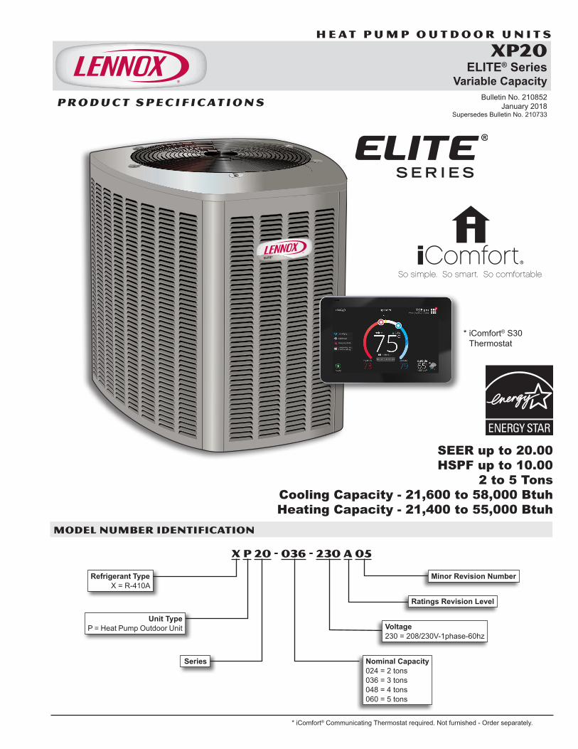
SEER up to 20.00HSPF up to 10.00
2 to 5 TonsCooling Capacity - 21,600 to 58,000 BtuhHeating Capacity - 21,400 to 55,000 Btuh
H E A T P U M P O U T D O O R U N I T S
XP20ELITE® Series
Variable Capacity Bulletin No. 210852
January 2018 Supersedes Bulletin No. 210733
MODEL NUMBER IDENTIFICATION
P R O D U C T S P E C I F I C AT I O N S
X P 20 - 036 - 230 A 05
Series
Unit Type P = Heat Pump Outdoor Unit
Refrigerant Type X = R-410A
Nominal Capacity 024 = 2 tons 036 = 3 tons 048 = 4 tons 060 = 5 tons
Minor Revision Number
Voltage 230 = 208/230V-1phase-60hz
Ratings Revision Level
XP20 2-5 TON HEAT PUMPS
* iComfort® S30 Thermostat
* iComfort® Communicating Thermostat required. Not furnished - Order separately.
XP20 - 2 to 5 Ton Heat Pump / Page 2
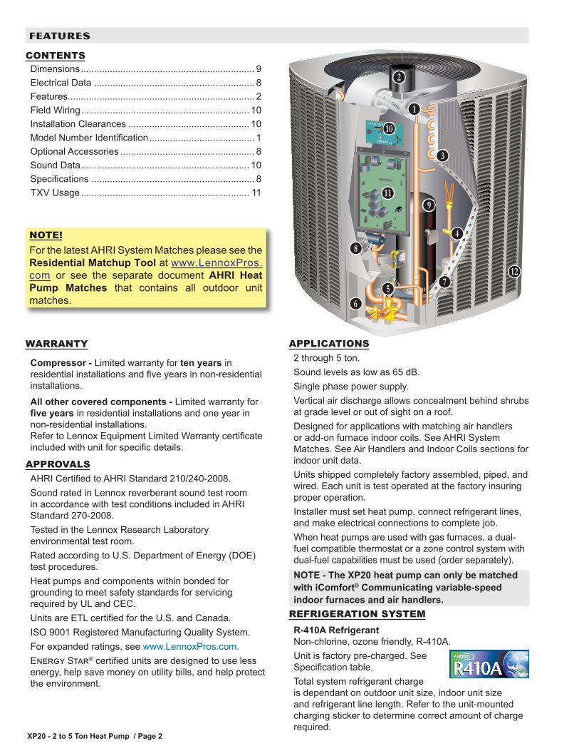
WARRANTY
Compressor - Limited warranty for ten years in residential installations and five years in non-residential installations.All other covered components - Limited warranty for five years in residential installations and one year in non-residential installations.Refer to Lennox Equipment Limited Warranty certificate included with unit for specific details.
APPROVALSAHRI Certified to AHRI Standard 210/240-2008.Sound rated in Lennox reverberant sound test room in accordance with test conditions included in AHRI Standard 270-2008.Tested in the Lennox Research Laboratory environmental test room.Rated according to U.S. Department of Energy (DOE) test procedures.Heat pumps and components within bonded for grounding to meet safety standards for servicing required by UL and CEC.Units are ETL certified for the U.S. and Canada.ISO 9001 Registered Manufacturing Quality System.For expanded ratings, see www.LennoxPros.com.Energy Star® certified units are designed to use less energy, help save money on utility bills, and help protect the environment.
APPLICATIONS2 through 5 ton.Sound levels as low as 65 dB.Single phase power supply.Vertical air discharge allows concealment behind shrubs at grade level or out of sight on a roof.Designed for applications with matching air handlers or add-on furnace indoor coils. See AHRI System Matches. See Air Handlers and Indoor Coils sections for indoor unit data.Units shipped completely factory assembled, piped, and wired. Each unit is test operated at the factory insuring proper operation.Installer must set heat pump, connect refrigerant lines, and make electrical connections to complete job.When heat pumps are used with gas furnaces, a dual-fuel compatible thermostat or a zone control system with dual-fuel capabilities must be used (order separately).NOTE - The XP20 heat pump can only be matched with iComfort® Communicating variable-speedindoor furnaces and air handlers.
REFRIGERATION SYSTEMR-410A RefrigerantNon-chlorine, ozone friendly, R-410A.Unit is factory pre-charged. See Specification table.Total system refrigerant charge is dependant on outdoor unit size, indoor unit size and refrigerant line length. Refer to the unit-mounted charging sticker to determine correct amount of charge required.
B
D
F
G
H
I
J
K
L
M
CONTENTSDimensions .................................................................. 9Electrical Data ............................................................. 8Features....................................................................... 2Field Wiring ................................................................ 10Installation Clearances .............................................. 10Model Number Identification ........................................ 1Optional Accessories ................................................... 8Sound Data ................................................................ 10Specifications .............................................................. 8TXV Usage ................................................................ 11
FEATURES
C
ENOTE!For the latest AHRI System Matches please see the Residential Matchup Tool at www.LennoxPros.com or see the separate document AHRI Heat Pump Matches that contains all outdoor unit matches.

XP20 - 2 to 5 Ton Heat Pump / Page 3
REFRIGERATION SYSTEM (continued)
Outdoor Coil FanDirect drive fan moves large air volumes uniformly through entire condenser coil for high refrigerant cooling capacity.Vertical air discharge minimizes operating sounds and eliminates damage to lawn and shrubs.Fan guard constructed of corrosion-resistant PVC (polyvinyl chloride) coated steel.Fan service access accomplished by removal of fan guard.Variable-Speed Outdoor Coil Fan Motor With Integrated ControlOutdoor coil fan motor with integrated control is programmed for variable capacity operation. Fan speed is directly controlled by the iComfort® communications between the outdoor unit iComfort® Communicating control and the iComfort® Communicating Thermostat.Fan motor is inherently protected.Motor totally enclosed for maximum protection from weather, dust and corrosion.
Copper Tube/Enhanced Fin CoilLennox designed and fabricated coil.Ripple-edged aluminum fins.Copper tube construction.Lanced fins provide maximum exposure of fin surface to air stream resulting in excellent heat transfer.Fin collars grip tubing for maximum contact area.Inverted coil circuiting prevents ice buildup at coil base in low ambients. Discharge gas enters bottom of coil during defrost and heat of refrigerant flows counter to water drainage resulting in extremely clean and unobstructed fins and tubes.Fin spacing allows rapid and complete water drainage.Flared shoulder tubing connections/silver soldering construction.Coil is factory tested under high pressure to insure leakproof construction.Entire coil is accessible for cleaning.
Expansion Valve - Outdoor UnitDesigned and sized specifically for use in heat pump system.Sensing bulb is located on the line between reversing valve and the coil thus sensing suction temperature in the heat cycle.Factory installed and piped.
Discharge Temperature SwitchShuts off unit if operating conditions cause the compressor discharge line temperature to rise above setpoint.Protects compressor from excessive pressure / temperature.Automatic reset when temperature drops below
AB
C
D
E
setpoint.
High Pressure SwitchShuts off unit if abnormal operating conditions cause the discharge pressure to rise above setting.Protects compressor from excessive condensing pressure.Auto-reset.
Low Pressure SwitchShuts off unit if suction pressure falls below setting.Provides loss of charge and freeze-up protection.Auto-reset.
Hi-Capacity Liquid Line DrierFactory installed in the liquid line, the drier traps moisture or dirt that could contaminate the refrigerant system.100% molecular-sieve bead type drier.
Reversing Valve4-way interchange reversing valve effects a rapid change in direction of refrigerant flow resulting in quick changeover from cooling to heating and vice versa.Valve operates on pressure differential between outdoor unit and indoor unit of the system. Factory installed.
Optional Accessories
Expansion Valve KitsMust be ordered separately and field installed on certain indoor units. See TXV Usage table.Chatleff style fitting.
FreezestatInstalls on or near the discharge line of the evaporator or on the suction line.Senses suction line temperature and cycles thecompressor off when suction line temperature falls below its setpoint.Opens at 29°F and closes at 58°F.
Refrigerant Line KitsRefrigerant lines (suction & liquid) are shipped refrigeration clean. Lines are cleaned, dried, pressurized, and sealed at factory.Suction line fully insulated.L15 lines are stubbed at both ends.See Specifications table for selection.Not available for -060 model and must be field fabricated.NOTE - The XP20 is a variable capacity heat pump utilizing variable speed compressor technology. With the variable speed compressor and variable pumping capacity, additional consideration must be given to refrigerant piping sizing and application.Please refer to the Installation Instructions or Service Literature for Line Set Requirements and Refrigerant Piping Guidelines.
F
G
H
I
FEATURES
XP20 - 2 to 5 Ton Heat Pump / Page 4
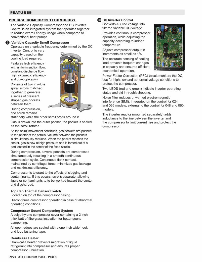
PRECISE COMFORT® TECHNOLOGYThe Variable Capacity Compressor and DC Inverter Control is an integrated system that operates together to reduce overall energy usage when compared to conventional heat pumps. Variable Capacity Scroll CompressorOperates on a variable frequency determined by the DC Inverter Control to vary capacity based on the cooling load required.Features high efficiency with uniform suction flow, constant discharge flow, high volumetric efficiency and quiet operation.Consists of two involute spiral scrolls matched together to generate a series of crescent shaped gas pockets between them.During compression, one scroll remains stationary while the other scroll orbits around it.Gas is drawn into the outer pocket, the pocket is sealed as the scroll rotates.As the spiral movement continues, gas pockets are pushed to the center of the scrolls. Volume between the pockets is simultaneously reduced. When the pocket reaches the center, gas is now at high pressure and is forced out of a port located in the center of the fixed scrolls. During compression, several pockets are compressed simultaneously resulting in a smooth continuous compression cycle. Continuous flank contact, maintained by centrifugal force, minimizes gas leakage and maximizes efficiency. Compressor is tolerant to the effects of slugging and contaminants. If this occurs, scrolls separate, allowing liquid or contaminants to to be worked toward the center and discharged.
Top Cap Thermal Sensor SwitchLocated on top of the compressor casing. Discontinues compressor operation in case of abnormal operating conditions.
Compressor Sound Dampening System A polyethylene compressor cover containing a 2 inch thick batt of fiberglass insulation for better sound dampening.All open edges are sealed with a one-inch wide hook and loop fastening tape.
Crankcase HeaterCrankcase heater prevents migration of liquid refrigerant into compressor and ensures proper compressor lubrication.
J
DC Inverter ControlConverts AC line voltage into filtered variable DC voltage.Provides continuous compressor operation, while adjusting the capacity according to indoor temperature.Adjusts compressor output in increments as small as 1%.The accurate sensing of cooling load prevents frequent changes in capacity and ensures efficient, economical operation.Power Factor Correction (PFC) circuit monitors the DC bus for high, low and abnormal voltage conditions to protect the compressor.Two LEDS (red and green) indicate inverter operating status and aid in troubleshooting.Noise filter reduces unwanted electromagnetic interference (EMI). Integrated on the control for 024 and 036 models, external to the control for 048 and 060 models.The inverter reactor (mounted separately) adds inductance to the line between the inverter and the compressor to limit current rise and protect the compressor.
K
FEATURES

XP20 - 2 to 5 Ton Heat Pump / Page 5
CONTROLSiComfort® Communicating Control Advanced control communicates information about various operating parameters in the air conditioner to the iComfort® Communicating Thermostat to constantly maintain the highest level of comfort, performance and efficiency available.Auto Configuration - On start-up the control automatically sends a description of the unit to the iComfort® Communicating Thermostat to automatically configure the features available.Control also features:• Seven-Segment Display shows information about
outdoor unit type and capacity and also displays alerts for common fault conditions (electrical and mechanical).
• Low voltage protection prevents compressor operation when voltage is not within the specified range.
• Compressor defrost shift delay - Adjustable 0 (factory) or 30 seconds.
• Demand defrost using outdoor ambient air temperature, coil temperature and compressor run-time inputs. 14 minute maximum defrost time.
• Selectable defrost termination temperature - 50, 70, 90 or 100ºF. Default setting is 50°F.
• High and low pressure switch monitoring with provisions for lockout.
• Five-Strike lockout protection protects compressor.
• Discharge line temperature and outdoor air temperature monitoring.
• EEPROM storage of all local configurations.• Non-volatile memory storage of 100 alarm codes
with display of last 10 codes for troubleshooting.• Built-in low ambient control.
Low Ambient OperationCooling Mode - The heat pump can operate down to 0°F outdoor air temperature in the cooling mode.NOTE - A freezestat is recommended for extra protection during low ambient cooling operation.
Heating Mode (Low Temperature Protection) - Outdoor unit will not operate in the heating mode when the outdoor temperature is at or below –4°F. If the unit is operating and the outdoor temperature drops below –4°F, the unit will continue to operate until the room thermostat is satisfied or the outdoor temperature drops to –15°F.
L
Climate IQ™ TechnologyOptimizes dehumidification settings for specific climates to improve home comfort during cooling or heating operation.iComfort® S30 Thermostat Setting:• Climate IQ (Auto) - Dry, Normal, Basic and Humid
modes are automatically set based on the difference between the measured relative humidity and the relative humidity setting.
All modes are selected on the iComfort® Communicating Thermostat.iComfort Wi-Fi® Thermostat Settings:
Cooling ModeThree climate settings are available:
• Dry - The system supplies higher indoor airflow at all compressor capacities, increasing efficiency by operating at a higher sensible to total ratio.
• Moderate - The system supplies indoor airflow that balances efficiency and comfort.
• Humid - The system supplies lower indoor airflow at all compressor capacities, improving humidity removal by operating at a lower sensible to total ratio.
Heating ModeTwo climate settings are available:
• Comfort - The system reduces indoor airflow, increasing supply air temperature.
• Normal - Standard system operation.
Outdoor Air Temperature Sensor Used with iComfort® Communicating Thermostats.Sensor allows thermostat to display outdoor temperature. Sensor is auto-detected when connected to thermostat.
FEATURES
XP20 - 2 to 5 Ton Heat Pump / Page 6
FEATURES
CONTROLS (continued)
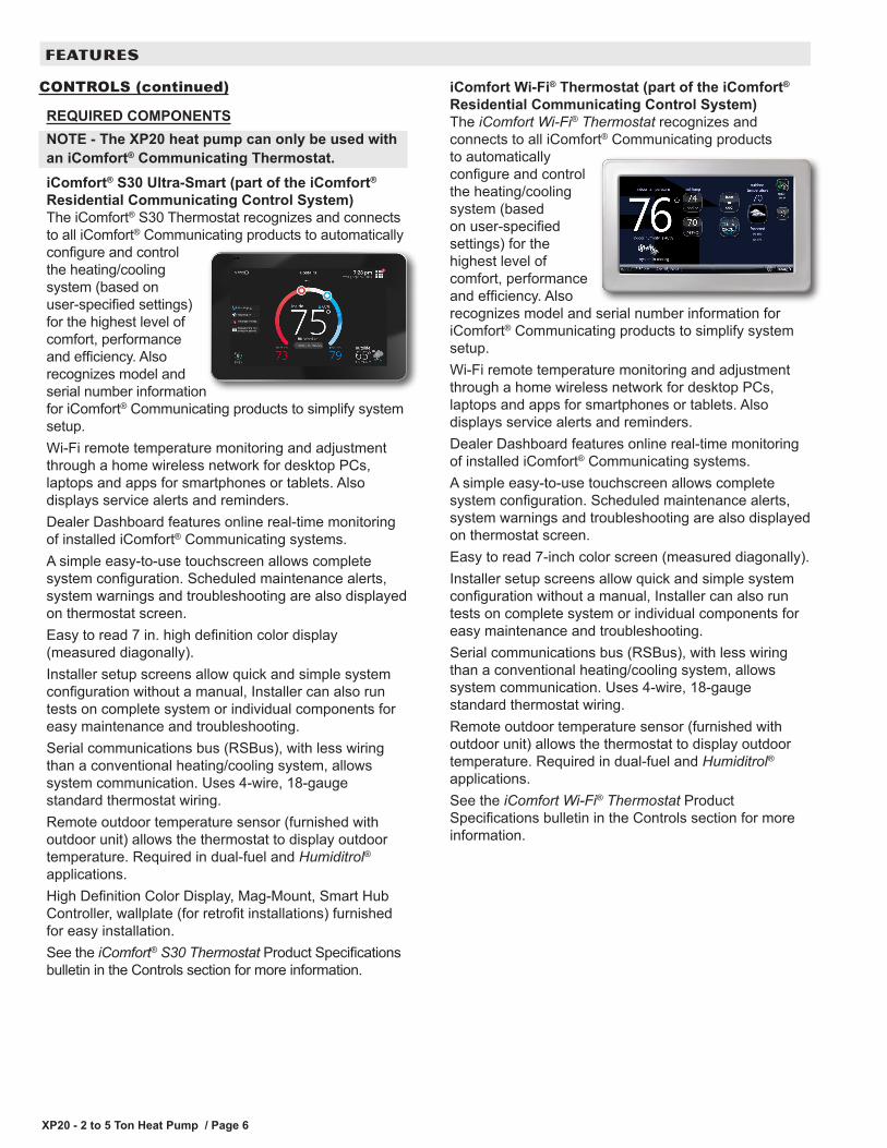
REQUIRED COMPONENTSNOTE - The XP20 heat pump can only be used withan iComfort® Communicating Thermostat.iComfort® S30 Ultra-Smart (part of the iComfort® Residential Communicating Control System)The iComfort® S30 Thermostat recognizes and connects to all iComfort® Communicating products to automatically configure and control the heating/cooling system (based on user-specified settings) for the highest level of comfort, performance and efficiency. Also recognizes model and serial number information for iComfort® Communicating products to simplify system setup.Wi-Fi remote temperature monitoring and adjustment through a home wireless network for desktop PCs, laptops and apps for smartphones or tablets. Also displays service alerts and reminders.Dealer Dashboard features online real-time monitoring of installed iComfort® Communicating systems. A simple easy-to-use touchscreen allows complete system configuration. Scheduled maintenance alerts, system warnings and troubleshooting are also displayed on thermostat screen.Easy to read 7 in. high definition color display (measured diagonally).Installer setup screens allow quick and simple system configuration without a manual, Installer can also run tests on complete system or individual components for easy maintenance and troubleshooting. Serial communications bus (RSBus), with less wiring than a conventional heating/cooling system, allows system communication. Uses 4-wire, 18-gauge standard thermostat wiring.Remote outdoor temperature sensor (furnished with outdoor unit) allows the thermostat to display outdoor temperature. Required in dual-fuel and Humiditrol® applications.High Definition Color Display, Mag-Mount, Smart Hub Controller, wallplate (for retrofit installations) furnished for easy installation.See the iComfort® S30 Thermostat Product Specifications bulletin in the Controls section for more information.
iComfort Wi-Fi® Thermostat (part of the iComfort® Residential Communicating Control System)The iComfort Wi-Fi® Thermostat recognizes and connects to all iComfort® Communicating products to automatically configure and control the heating/cooling system (based on user-specified settings) for the highest level of comfort, performance and efficiency. Also recognizes model and serial number information for iComfort® Communicating products to simplify system setup.Wi-Fi remote temperature monitoring and adjustment through a home wireless network for desktop PCs, laptops and apps for smartphones or tablets. Also displays service alerts and reminders.Dealer Dashboard features online real-time monitoring of installed iComfort® Communicating systems. A simple easy-to-use touchscreen allows complete system configuration. Scheduled maintenance alerts, system warnings and troubleshooting are also displayed on thermostat screen.Easy to read 7-inch color screen (measured diagonally). Installer setup screens allow quick and simple system configuration without a manual, Installer can also run tests on complete system or individual components for easy maintenance and troubleshooting. Serial communications bus (RSBus), with less wiring than a conventional heating/cooling system, allows system communication. Uses 4-wire, 18-gauge standard thermostat wiring.Remote outdoor temperature sensor (furnished with outdoor unit) allows the thermostat to display outdoor temperature. Required in dual-fuel and Humiditrol® applications.See the iComfort Wi-Fi® Thermostat Product Specifications bulletin in the Controls section for more information.
XP20 - 2 to 5 Ton Heat Pump / Page 7
FEATURES
CABINETHeavy-gauge steel constructionPre-painted cabinet finish.Control box is conveniently located with all controls factory wired.Large removable panel provides service access.Drainage holes are provided in base section for moisture removal.High density polyethylene unit support feet raise the unit off of the mounting surface, away from damaging moisture.
PermaGuard™ Unit BaseDurable zinc-coated base section resists rust and corrosion.
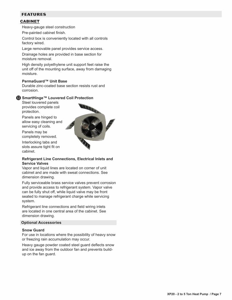
SmartHinge™ Louvered Coil ProtectionSteel louvered panels provides complete coil protection.Panels are hinged to allow easy cleaning and servicing of coils.Panels may be completely removed.Interlocking tabs and slots assure tight fit on cabinet.
Refrigerant Line Connections, Electrical Inlets and Service ValvesVapor and liquid lines are located on corner of unit cabinet and are made with sweat connections. See dimension drawing. Fully serviceable brass service valves prevent corrosion and provide access to refrigerant system. Vapor valve can be fully shut off, while liquid valve may be front seated to manage refrigerant charge while servicing system.Refrigerant line connections and field wiring inlets are located in one central area of the cabinet. See dimension drawing.
Optional Accessories
Snow GuardFor use in locations where the possibility of heavy snow or freezing rain accumulation may occur.Heavy gauge powder coated steel guard deflects snow and ice away from the outdoor fan and prevents build-up on the fan guard.
M
XP20 - 2 to 5 Ton Heat Pump / Page 8
SPECIFICATIONS General Data
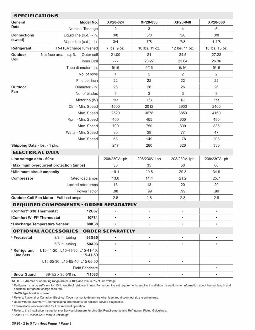
Model No. XP20-024 XP20-036 XP20-048 XP20-060Nominal Tonnage 2 3 4 5
Connections (sweat)
Liquid line (o.d.) - in. 3/8 3/8 3/8 3/8
Vapor line (o.d.) - in. 3/4 7/8 7/8 1-1/8
Refrigerant 1 R-410A charge furnished 7 lbs. 9 oz. 10 lbs. 11 oz. 12 lbs. 11 oz. 13 lbs. 15 oz.
Outdoor Coil
Net face area - sq. ft. Outer coil 21.00 21 24.5 27.22
Inner Coil - - - 20.27 23.64 26.36
Tube diameter - in. 5/16 5/16 5/16 5/16
No. of rows 1 2 2 2
Fins per inch 22 22 22 22
Outdoor Fan
Diameter - in. 26 26 26 26
No. of blades 3 3 3 3
Motor hp (W) 1/3 1/3 1/3 1/3
Cfm - Min. Speed 1500 2012 2900 2400
Max. Speed 2520 3678 3850 4160
Rpm - Min. Speed 400 405 600 480
Max. Speed 700 750 800 835
Watts - Min. Speed 30 29 77 47
Max .Speed 63 149 178 203
Shipping Data - lbs. - 1 pkg. 247 280 326 330
ELECTRICAL DATA Line voltage data - 60hz 208/230V-1ph 208/230V-1ph 208/230V-1ph 208/230V-1ph2 Maximum overcurrent protection (amps) 30 35 50 603 Minimum circuit ampacity 19.1 20.8 29.3 34.9
Compressor Rated load amps 13.0 14.4 21.2 25.7
Locked rotor amps 13 13 20 20
Power factor .98 .99 .99 .99
Outdoor Coil Fan Motor - Full load amps 2.8 2.8 2.8 2.8
REQUIRED COMPONENTS - ORDER SEPARATELYiComfort® S30 Thermostat 12U67 • • • •
iComfort Wi-Fi® Thermostat 10F81 • • • •4 Discharge Temperature Sensor 88K38 • • • •
OPTIONAL ACCESSORIES - ORDER SEPARATELY5 Freezestat 3/8 in. tubing 93G35 • • • •
5/8 in. tubing 50A93 • • • •6 Refrigerant
Line SetsL15-41-20 , L15-41-30, L15-41-40,
L15-41-50•
L15-65-30, L15-65-40, L15-65-50 • •
Field Fabricate •7 Snow Guard 39-1/2 x 35-5/8 in. Y1033 • • • •NOTE - Extremes of operating range are plus 10% and minus 5% of line voltage.1 Refrigerant charge sufficient for 15 ft. length of refrigerant lines. For longer line set requirements see the Installation Instructions for information about line set length and
additional refrigerant charge required.2 HACR type breaker or fuse.3 Refer to National or Canadian Electrical Code manual to determine wire, fuse and disconnect size requirements.4 Used with the iComfort® Communicating Thermostats for optional service diagnostics.5 Freezestat is recommended for Low Ambient operation.6 Refer to the Installation Instructions or Service Literature for Line Set Requirements and Refrigerant Piping Guidelines.7 Adds 11-1/2 inches (292 mm) to unit height.

XP20 - 2 to 5 Ton Heat Pump / Page 9
Model No.A
in. mmXP20-024 39 991XP20-036 39 991XP20-048 45 1143XP20-060 45 1143
ELECTRICALINLETS
SIDE VIEW
DISCHARGE AIR
SUCTION LINECONNECTION
LIQUID LINECONNECTION
A
4-1/4(108)4-3/4(121)
1 (25)
2 (51)
END VIEW
TOP VIEW
SUCTION LINECONNECTION
LIQUID LINECONNECTION
UNIT SUPPORTFEET
BASE SECTION(Large Base)
26-7/8(683)
16-7/8(429)
8-3/4(222)
3-1/8(79)
4-5/8(117)
30-3/4(781)
3-3/4(95)
39-1/2 (1003) 35-1/2 (902)
DIMENSIONS - INCHES (MM)
XP20 - 2 to 5 Ton Heat Pump / Page 10
SeeNOTES
See NOTES
SeeNOTES
See NOTES ControlBox
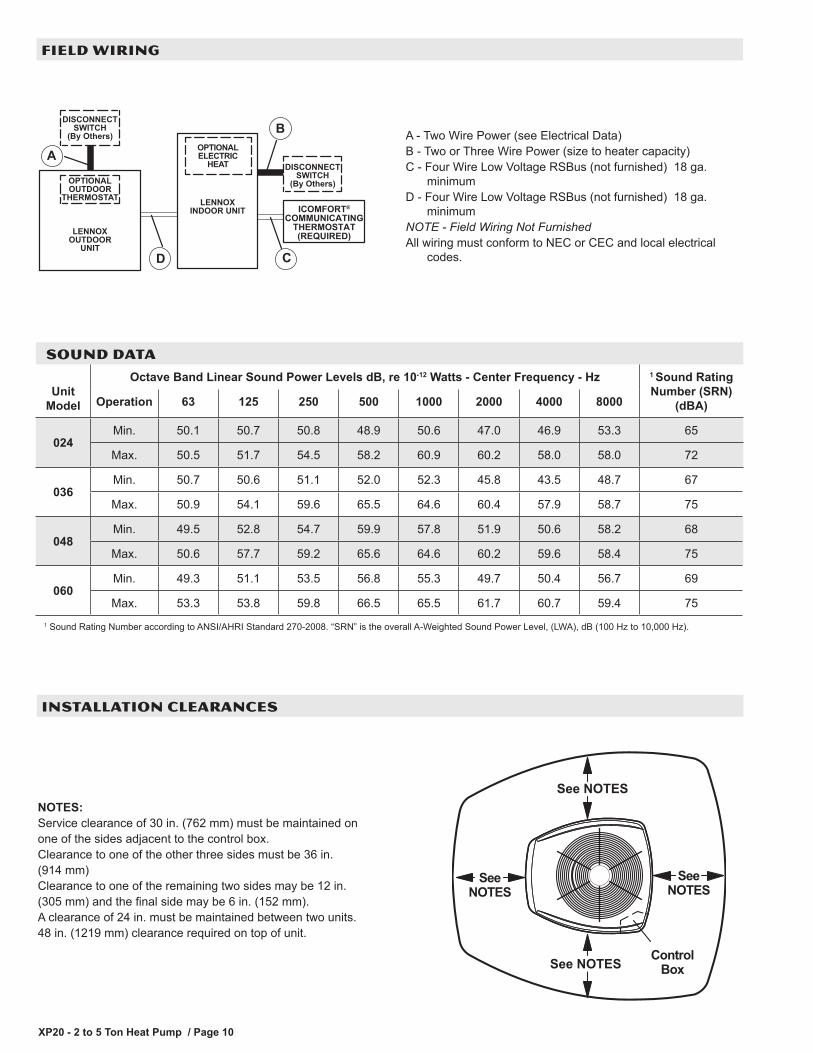
NOTES:Service clearance of 30 in. (762 mm) must be maintained onone of the sides adjacent to the control box.Clearance to one of the other three sides must be 36 in. (914 mm)Clearance to one of the remaining two sides may be 12 in. (305 mm) and the final side may be 6 in. (152 mm).A clearance of 24 in. must be maintained between two units.48 in. (1219 mm) clearance required on top of unit.
FIELD WIRING
INSTALLATION CLEARANCES
DISCONNECTSWITCH
(By Others)
OPTIONALOUTDOOR
THERMOSTAT LENNOXINDOOR UNIT
OPTIONALELECTRIC
HEAT
LENNOXOUTDOOR
UNIT
DISCONNECTSWITCH
(By Others)
A
B
CD
ICOMFORT®
COMMUNICATINGTHERMOSTAT(REQUIRED)
A - Two Wire Power (see Electrical Data)B - Two or Three Wire Power (size to heater capacity)C - Four Wire Low Voltage RSBus (not furnished) 18 ga.
minimumD - Four Wire Low Voltage RSBus (not furnished) 18 ga.
minimumNOTE - Field Wiring Not FurnishedAll wiring must conform to NEC or CEC and local electrical
codes.
SOUND DATA
Unit Model
Octave Band Linear Sound Power Levels dB, re 10-12 Watts - Center Frequency - Hz 1 Sound Rating Number (SRN)
(dBA)Operation 63 125 250 500 1000 2000 4000 8000
024Min. 50.1 50.7 50.8 48.9 50.6 47.0 46.9 53.3 65
Max. 50.5 51.7 54.5 58.2 60.9 60.2 58.0 58.0 72
036Min. 50.7 50.6 51.1 52.0 52.3 45.8 43.5 48.7 67
Max. 50.9 54.1 59.6 65.5 64.6 60.4 57.9 58.7 75
048Min. 49.5 52.8 54.7 59.9 57.8 51.9 50.6 58.2 68
Max. 50.6 57.7 59.2 65.6 64.6 60.2 59.6 58.4 75
060Min. 49.3 51.1 53.5 56.8 55.3 49.7 50.4 56.7 69
Max. 53.3 53.8 59.8 66.5 65.5 61.7 60.7 59.4 751 Sound Rating Number according to ANSI/AHRI Standard 270-2008. “SRN” is the overall A-Weighted Sound Power Level, (LWA), dB (100 Hz to 10,000 Hz).
XP20 - 2 to 5 Ton Heat Pump / Page 11
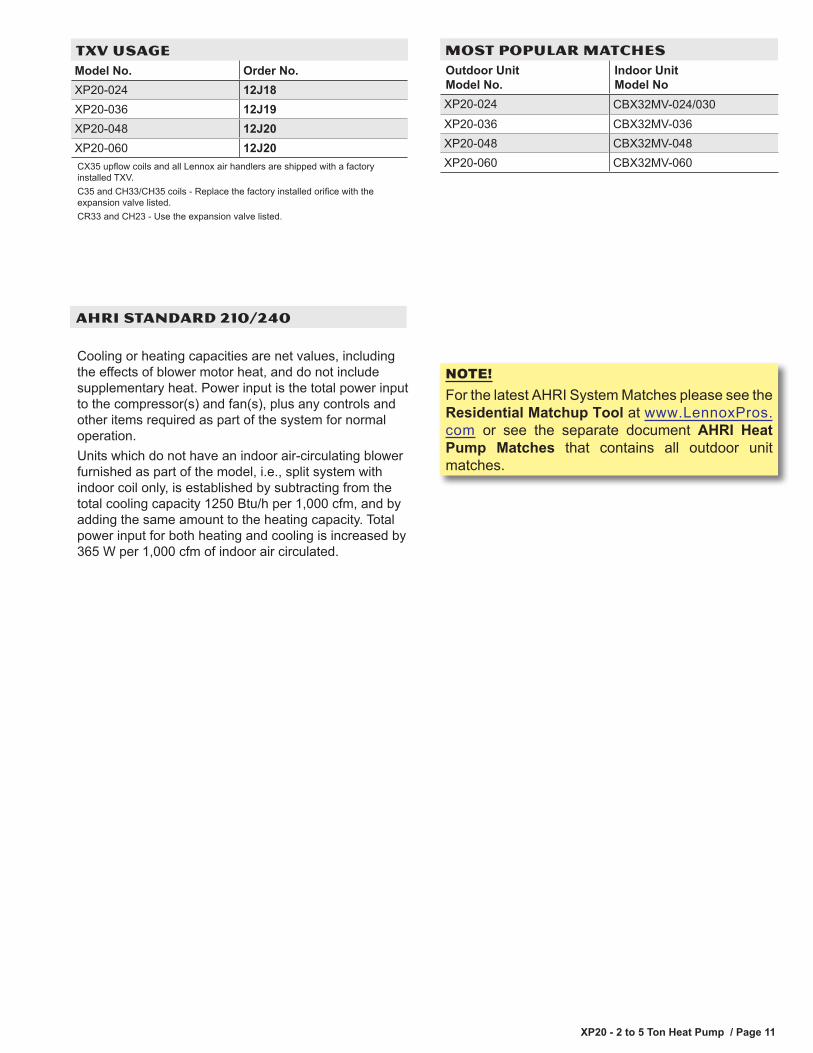
TXV USAGEModel No. Order No.XP20-024 12J18XP20-036 12J19XP20-048 12J20XP20-060 12J20CX35 upflow coils and all Lennox air handlers are shipped with a factory installed TXV.C35 and CH33/CH35 coils - Replace the factory installed orifice with the expansion valve listed.CR33 and CH23 - Use the expansion valve listed.
MOST POPULAR MATCHESOutdoor Unit Model No.
Indoor Unit Model No
XP20-024 CBX32MV-024/030XP20-036 CBX32MV-036XP20-048 CBX32MV-048XP20-060 CBX32MV-060
AHRI STANDARD 210/240
Cooling or heating capacities are net values, including the effects of blower motor heat, and do not include supplementary heat. Power input is the total power input to the compressor(s) and fan(s), plus any controls and other items required as part of the system for normal operation.Units which do not have an indoor air-circulating blower furnished as part of the model, i.e., split system with indoor coil only, is established by subtracting from the total cooling capacity 1250 Btu/h per 1,000 cfm, and by adding the same amount to the heating capacity. Total power input for both heating and cooling is increased by 365 W per 1,000 cfm of indoor air circulated.
NOTE!For the latest AHRI System Matches please see the Residential Matchup Tool at www.LennoxPros.com or see the separate document AHRI Heat Pump Matches that contains all outdoor unit matches.
NOTE - Due to Lennox’ ongoing commitment to quality, Specifications, Ratings and Dimensions subject to change without notice and without incurring liability. Improper installation, adjustment, alteration, service or maintenance can cause property damage or personal injury. Installation and service must be performed by a qualified installer and servicing agency. ©2018 Lennox Industries, Inc.
Visit us at www.lennox.com For the latest technical information, www.LennoxPros.com Contact us at 1-800-4-LENNOX
REVISIONS
REVISIONS
Sections Description of Change
Document Moved all AHRI Matches to a separate document.