heat pipe heat exchanger with two levels of isolation for ... pipe heat exchanger with two levels of...
TRANSCRIPT

ABSTRACT
Current environmental control thermal management systems use a two-loop, two-exchanger arrangement to isolate the crew from potentially hazardous ammonia or Freon in the final heat reject loop. Although that method does provide isolation, it is not fault-tolerant and does not provide advance warning of an exchanger leak. A heat pipe heat exchanger under development improves the existing system by providing two levels of isolation between the fluid streams. The new heat exchanger is fault-tolerant and can provide advance warning of a leak. Described are the heat exchanger design, test results from a sub-scale exchanger segment, and the results of a design optimization and trade study.
INTRODUCTION
One key function of the environmental control system of a manned spacecraft is heat rejection from the crew compartment. This must be accomplished by methods that have little or no risk of introducing hazardous fluids or materials into the crew compartment in the event of a failure or malfunction. The systems currently in use in the Shuttle and Space Station are based on two fluid loops and two heat exchangers. Heated air from the crew compartment passes through one side of a heat exchanger and is transferred to a water loop. That water loop moves the heat to a second exchanger, which then transfers the heat to an outer pumped loop system based on either Freon 21 (Shuttle) or ammonia (Space Station). The Freon or ammonia in the outer loop circulates through radiator panels which serve as the ultimate heat sink.
The outer loop fluids drive the need for a two-exchanger system. These two fluids are used in the radiators because of their very low freezing points and good thermal properties. They are, however, hazardous to the crew in even small quantities. In small quantities ammonia has an unpleasant odor. In slightly larger quantities it will irritate or damage mucous membranes
such as the eyes and the respiratory system. Both ammonia and Freon can displace air and cause suffocation. The problem is exacerbated by the fluids’ low boiling points. The fluids will leak as liquids but will readily expand to a gas that is several hundred times greater in volume.
The two-loop system provides isolation as well as advance notice of leaks. The presence of two exchangers requires that two surfaces be breached before ammonia can reach the crew compartment. Since the water loop is periodically sampled, a leak in the ammonia exchanger will become evident before the ammonia bridges the second exchanger. The system also provides physical isolation between the ammonia system and the crew compartment. The piping and water loop allow the ammonia exchanger to be placed far enough away that a leak in the ammonia system cannot reach the crew compartment.
Although this system does provide isolation between the loops and advance warning of a leak, it is not ideal. The barrier can be overwhelmed by a moderate leak. If a substantial amount of ammonia leaks into the water loop, it will be vented into the crew compartment by de-aerators that are part of the water loop. Also, the system cannot immediately discriminate between a large and a small leak. Instead, secondary indicators such as the level of fluid in the ammonia accumulators must be monitored.
Due to the drawbacks with the current system and the hazardous nature of the outer loop fluid, there is a clear need for a fault-tolerant heat exchanger on the ammonia side that would itself provide two levels of isolation between the fluid loops, and advance warning of leaks.
CURRENT ISOLATED EXCHANGER DESIGN
The heat exchangers of the current system are based on folded or pleated metal fins mounted on opposite sides of a separator or face sheet. Heat is absorbed from the first fluid stream as it passes through the triangular
2006-01-2163
Heat Pipe Heat Exchanger with Two Levels of Isolation
for Environmental Control of Manned Spacecraft
Crew Compartment
David B. Sarraf Advanced Cooling Technologies, Inc.
Copyright © 2006 SAE International

channels formed by the fins. It is then conducted up the fins, through the face sheet, and into the second set of fins. There, the heat is absorbed by the second fluid stream. The actual exchanger is made of a stack of many such elements that are connected together with manifolds. The entire assembly is either brazed or welded to produce a hermetic cross-flow heat exchanger.
By adding another face sheet and an isolator layer, the existing heat exchanger design can be upgraded to provide two levels of isolation between the fluid streams. This is shown in Figure 1. Heat now flows through both face sheets and the isolation/thermal link layer, and the fluid must breach two face sheets before mixing occurs. The pressure in the isolation layer between the two face sheets can be monitored to serve as a tell-tale for leakage through either face sheet. That would provide advanced warning and allow the heat exchanger to be repaired or removed from service before both sheets were breached. A folded fin is shown as the isolation/thermal link layer. Other materials, including graphite composites or graphite foam, could be used instead of the metal fin and may offer improved thermal performance at the expense of greater difficulty in joining the dissimilar materials.
Figure 1 Schematic of a folded fin heat exchanger element with an isolation layer
This design is still not ideal. The isolation layer must be added to every stack or pair of exchanger elements, which means that the additional heat exchanger mass increases linearly with layer count and exchanger capacity. In the case of the system discussed earlier, estimates showed that the isolation layers doubled the mass of the exchanger from 10.9 to 21.7 kg (24 pounds to 48 pounds). Problems with joining/sealing and manifold construction are exacerbated in this design. In addition to the four manifolds already required to convey fluid to the exchanger, the voids in the isolation layers must be coupled to a port or device that can detect fluid leakage through one or more face sheets. This greatly
increases the complexity of the manifolds and increases the length of joints requiring a hermetic seal.
HEAT PIPE HEAT EXCHANGERS
Heat pipes transport heat by two-phase flow of a working fluid. Shown in Figure 2, a heat pipe is a vacuum tight device consisting of a working fluid and a wick structure. The heat input vaporizes the liquid working fluid inside the wick in the evaporator section. The vapor, carrying the latent heat of vaporization, flows towards the cooler condenser section. In the condenser, the vapor condenses and gives up its latent heat. The condensed liquid returns to the evaporator through the wick structure by capillary action. Operation is entirely passive and relies on no moving parts. The phase change processes and two-phase flow circulation continue as long as the temperature gradient between the evaporator and condenser are maintained.
Figure 2. Schematic of heat pipe showing fluid flow and operation
In Figure 2, the heat pipe is shown with the evaporator below the condenser. It is possible to operate the heat pipe with the evaporator elevated if a suitable wick structure is provided. The wick structure is a capillary pump which overcomes the pressure drops incurred by the flow of liquid and vapor, including lifting the condensate against gravity as needed. Wicks with fine pores in combination with working fluids having high surface tension will develop large pumping pressures and can allow operation with the heat pipe vertical and the evaporator down. Examples of this include copper/water heat pipes with sintered powder metal wicks used for electronics cooling. Wicks with larger pores and working fluids with moderate surface tension will provide less pumping pressure and allow only slight evaporator elevations. Typical examples include the axial groove aluminum/ammonia heat pipes commonly used on spacecraft.
A single heat pipe heat exchanger element is shown in Figure 3. Heat is absorbed from the first fluid stream by the lower set of plate fins. It is conducted into the heat
Fluid1 Path
Folded Fin
Fluid 2 Path
Face Sheet
Isolator /
thermal link
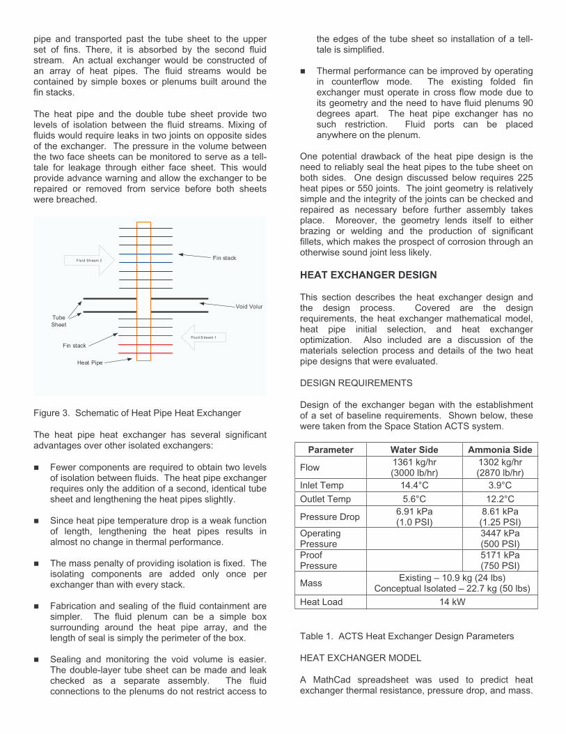
pipe and transported past the tube sheet to the upper set of fins. There, it is absorbed by the second fluid stream. An actual exchanger would be constructed of an array of heat pipes. The fluid streams would be contained by simple boxes or plenums built around the fin stacks.
The heat pipe and the double tube sheet provide two levels of isolation between the fluid streams. Mixing of fluids would require leaks in two joints on opposite sides of the exchanger. The pressure in the volume between the two face sheets can be monitored to serve as a tell-tale for leakage through either face sheet. This would provide advance warning and allow the exchanger to be repaired or removed from service before both sheets were breached.
Figure 3. Schematic of Heat Pipe Heat Exchanger
The heat pipe heat exchanger has several significant advantages over other isolated exchangers:
Fewer components are required to obtain two levels of isolation between fluids. The heat pipe exchanger requires only the addition of a second, identical tube sheet and lengthening the heat pipes slightly.
Since heat pipe temperature drop is a weak function of length, lengthening the heat pipes results in almost no change in thermal performance.
The mass penalty of providing isolation is fixed. The isolating components are added only once per exchanger than with every stack.
Fabrication and sealing of the fluid containment are simpler. The fluid plenum can be a simple box surrounding around the heat pipe array, and the length of seal is simply the perimeter of the box.
Sealing and monitoring the void volume is easier. The double-layer tube sheet can be made and leak checked as a separate assembly. The fluid connections to the plenums do not restrict access to
the edges of the tube sheet so installation of a tell-tale is simplified.
Thermal performance can be improved by operating in counterflow mode. The existing folded fin exchanger must operate in cross flow mode due to its geometry and the need to have fluid plenums 90 degrees apart. The heat pipe exchanger has no such restriction. Fluid ports can be placed anywhere on the plenum.
One potential drawback of the heat pipe design is the need to reliably seal the heat pipes to the tube sheet on both sides. One design discussed below requires 225 heat pipes or 550 joints. The joint geometry is relatively simple and the integrity of the joints can be checked and repaired as necessary before further assembly takes place. Moreover, the geometry lends itself to either brazing or welding and the production of significant fillets, which makes the prospect of corrosion through an otherwise sound joint less likely.
HEAT EXCHANGER DESIGN
This section describes the heat exchanger design and the design process. Covered are the design requirements, the heat exchanger mathematical model, heat pipe initial selection, and heat exchanger optimization. Also included are a discussion of the materials selection process and details of the two heat pipe designs that were evaluated.
DESIGN REQUIREMENTS
Design of the exchanger began with the establishment of a set of baseline requirements. Shown below, these were taken from the Space Station ACTS system.
Parameter Water Side Ammonia Side
Flow1361 kg/hr (3000 lb/hr)
1302 kg/hr (2870 lb/hr)
Inlet Temp 14.4°C 3.9°C
Outlet Temp 5.6°C 12.2°C
Pressure Drop 6.91 kPa (1.0 PSI)
8.61 kPa (1.25 PSI)
OperatingPressure
3447 kPa (500 PSI)
ProofPressure
5171 kPa (750 PSI)
MassExisting – 10.9 kg (24 lbs)
Conceptual Isolated – 22.7 kg (50 lbs)
Heat Load 14 kW
Table 1. ACTS Heat Exchanger Design Parameters
HEAT EXCHANGER MODEL
A MathCad spreadsheet was used to predict heat exchanger thermal resistance, pressure drop, and mass.
F luid Stream 2
Fluid S tream 1
Tube
Sheet
Heat Pipe
Void Volum
Fin stack
Fin stack

Thermal resistance was the sum of the resistance of each individual fin stack (upper and lower) and the heat pipe thermal resistance. Both the thermal resistance and the fluid pressure drop of each fin stack were calculated using an empirical correlation developed by Webb and Gray (below). Reynolds number was monitored to be sure that the model was being used within the bounds of those correlations. Heat pipe thermal resistance was the sum of the expected film coefficients of the evaporator and condenser and resistance of the heat pipe walls. Vapor pressure drop was minimal so that thermal resistance was ignored. Entry and exit losses of the exchanger end fittings or pressure losses due to internal fluid distribution were not considered in this model. Fluid properties were taken as constant since the temperature differences were small.
The Gray and Webb model treats fluid flow over a single-sided bank of finned isothermal tubes. A multiple-regression analysis was conducted on a series of finned-tube heat exchangers of known performance. That allowed prediction of pressure drop and thermal resistance based on exchanger geometry and the fluid Reynolds number. The contribution of the tube bank and the fin bank were considered separately for both pressure drop and thermal resistance. Total pressure drop was the superposition of the tube bank and fin pressure drops. Thermal resistance was the sum of the fin and tube bank resistances. The correlation was developed for a four-row exchanger. A correction factor was added for exchangers having less than four rows. A comparison of the resulting empirical model with known exchanger performance showed agreement with RMS errors of less than 7.3%.
The model assumed a non-optimized or conventional envelope design. Mass was computed by summing the known mass of the fins and heat pipes and the predicted mass of a cylindrical envelope, circular tube sheet, and hemispherical end caps of sufficient thickness to withstand the maximum expected operating pressure. The mass of bolting flanges to mate with the tube sheet were also included. The mass of the fluid contained in the exchanger was not included.
INITIAL HEAT PIPE SELECTION
Based on the initial exchanger scoping calculations the heat pipe diameter was established. It was constrained by the tube bank pressure drop, fin efficiency, materials of construction (including working fluid selection), and axial heat flux. The exchanger model showed that many smaller pipes, more closely spaced were better than fewer large-diameter pipes, widely spaced. The smallest practical heat pipe diameter based on ease of construction was 12.7 mm (½”) OD. That yielded an expected heat pipe power of between 60 and 120 watts with a required QL (length x power) product as high as 33 watt-meters.
The heat pipe working fluid and wick structure were selected next. The choice of working fluid was limited by
vapor pressure (axial flux) and risk of freezing. Candidate fluids included water, methanol, acetone, ammonia, and propylene. Water, methanol, and acetone lacked sufficient vapor pressure at the expected heat pipe operating temperature and were dropped from further consideration. Wick structures were limited by the required QL product and the need to operate with the evaporator elevated slightly during ground testing. Calculations showed that powder metal and simple cylindrical screen wicks had insufficient permeability and would not work. Candidate wick structures included a screen I-beam and axially-extruded grooves. Since propylene lacks sufficient performance with these two wick structures it was dropped from further consideration.
Based on the initial exchanger scoping calculations, the heat pipe design was narrowed to ammonia with either extruded grooves or a screen I-beam wick. The resulting axial flux was well below the sonic limit of 123 kW/cm
2.
The entrainment limit was at least 2140 watts (screen wick) or 700 watts (axially-grooved wick). With the existence of a workable heat pipe wick and working fluid combination established, work returned to exchanger design.
MATERIALS EVALUATION
Prior to the heat exchanger design optimization work, candidate materials of construction were evaluated. Materials known to be compatible with the water loop include nickel, stainless steel, titanium, and inconel. Of those, only nickel would make a suitable fin material. The thermal conductivity of the other three was too low. Copper, the most thermally favorable material, was specifically proscribed. Prior use had shown that it caused changes in the composition of the coolant that increased corrosion of other elements in the loop. It also shed ions that eventually coated other components.
A bimetallic exchanger was one route to achieving compatibility. The materials in contact with water would be made of either nickel or stainless steel. The materials in contact with ammonia would be either nickel or aluminum. This would require bimetallic tubes for the heat pipes. These are readily available from a number of suppliers. The major problems include increased exchanger mass and no ready path to bonding of the fins to the heat pipes. Hydraulic expansion was not feasible due to the difference in material strength between the two halves of the tube, and brazing was not possible due to the presence of the low-melting aluminum portion. Epoxy or other organic bonds were not considered due to their poor life when immersed in water, and the potential to introduce contaminants.
The use of a barrier coating is another potential approach to improving compatibility. Nickel plating per MIL-C-26074E can produce an acceptable corrosion barrier layer. In the particular case of the heat exchanger, the layer would need to be produced by an autocatalytic (electroless) process since the majority of

the fin area would be shielded from the electrical field used for conventional electrolytic plating. A small test panel of aluminum was electroplated to that MIL standard then subjected to a salt fog test, which showed that the process could produce an acceptable barrier layer. A sample of foam was also plated, which showed that it was possible to provide coverage within the pores of the foam structure. Testing is ongoing for that sample. Electroplating allowed retention of the good performance and low mass of an all-aluminum exchanger and the opportunity to use a high-performance axially-grooved heat pipe wick. This approach was adopted for the remainder of the design work.
HEAT EXCHANGER OPTIMIZATION
The heat exchanger model was used to parametrically study a series of potential designs. The objective was to find the lowest-mass design that met the heat transfer and pressure drop requirements. Heat pipe arrays of 15x15, 14x14, and 12x12 (rows x columns) were examined. For each array the fin pitch, fin thickness, and stack height were varied to achieve the design goals while minimizing mass. Heat transfer capacity was fixed at 14 kW ±5%.
Three different heat pipe arrays were examined to determine the effect of flow path length on pressure drop. Smaller arrays of heat pipes would have shorter fins with shorter flow paths. For an exchanger of equal area the smaller arrays would therefore have more fins and more flow channels. The combination of shorter path length with additional parallel channels was expected to result in a lower pressure drop for the same heat exchange area. Designs were produced for several different pressure drops to determine the effect of pressure on exchanger mass.
The results of the optimization are shown in Figure 4. Table 2 shows the pressures considered at each case in the optimization exercise. The best or lowest-mass combination was found to be a 15 x 15 array of heat pipes using aluminum fins on the water and ammonia sides. The final exchanger design was taken at 2/3 of the allowable pressure drop. This allowed margin for entry and exit losses in an actual exchanger since the since they were not currently a part of the heat exchanger mathematical model. The finding that the lowest mass was obtained with a 15x15 array was unexpected. The additional mass of the exchangers based on smaller heat pipe arrays found to be due to the longer heat pipes required to accommodate the additional fins required.
Heat Exchanger Optimization - 225 Heat Pipes on 15 x 15 GridAluminum Fins on Water and Ammonia Sides
0
1
2
3
4
1 2 3 4 5
Case Number
Pre
ss
ure
Dro
p,
PS
I
0
10
20
30
40
50
60
70
80
Ma
ss
, p
ou
nd
s
Water Delta PAmmonia Delta P
Core MassExchanger Mass
Figure 4. Heat Exchanger Optimization Results
Table 2. Heat Exchanger Pressure Drops at Each Case Considered
HEAT PIPE DESIGN
Two different heat pipe wick designs were investigated. The first was based on a screen I-beam structure. Shown in Figure 5, it consists of multiple layers of screen formed into an I-beam or slab wick configuration. The body of the I-beam serves as a high-permeability conduit for return of condensate to the evaporator. Additional layers of screen serve as a circumferential wick that distributes liquid to the evaporator and condenser surfaces. Vapor flows in the voids between the screen and wall. Figure 6 below shows the predicted capillary limit for two different mesh sizes over a range of slab widths. The capillary limit increases with increasing beam width (fluid return cross section) until reaching a peak. At that point the vapor cross section begins to decrease rapidly and the predicted performance falls quickly.
Case Condition NH3 H2O
1 3.0 x system delta P 25.9 kPa (3.75 PSI)
20.7 kPa (3.00 PSI)
2 2.0x system delta P 17.2 kPa (2.50 PSI)
13.8 kPa (2.00 PSI)
3 1.5x system delta P 13.0 kPa (1.88 PSI)
10.3 kPa (1.5 PSI)
4 Meets system delta P 8.62 kPa (1.25 PSI)
6.89 kPa (1.00 PSI)
5 Meets 2/3 delta P 6.00 kPa (0.87 PSI)
4.55 kPa (0.67 PSI)

Figure 5. Cross-section of I-Beam wick Heat Pipe
Figure 5. I-Beam Wick Heat Pipe Cross Section
Figure 6. Predicted I-Beam Wick Heat Pipe Performance vs Beam (slab) thickness.
The second wick structure designed used axial grooves. Based on the 12.7 mm (½”) heat pipe OD, an extrusion profile was designed for adequate performance with minimal mass along with the ability to withstand the 5171 kPa (750 PSI) maximum working pressure. The resulting extrusion is shown in Figure 7. Its predicted performance is shown in Figure 8. At an operating temperature of 20°C, the ammonia version of this extrusion has an expected capability of 150 watt-meters, which is sufficient for the requirements of the heat exchanger. The plot also shows the clear superiority of ammonia as a working fluid. Propene is the nearest competitor to ammonia at the design operating temperature. It yields a capacity of just 20.3 watt-meters. That is less than the capability of a simple cylindrical screen/ammonia heat pipe and far less than the 33 watt-meter requirement of the heat exchanger.
Figure 7. Axially-Grooved Aluminum Extrusion
0
40
80
120
160
-60 -40 -20 0 20 40 60
Temperature [°C]
QL
[W
-m]
Ethane
Propene
Ammonia
Figure 8. Predicted Performance of Axially-Grooved Heat Pipes for Three Different Working Fluids
SCALABILITY STUDY
With the heat exchanger model expanded to include predictions of the enclosure and tube sheet mass, a mass comparison was made between the heat pipe heat exchanger and an isolated folded fin exchanger. The comparison showed the expected mass of each exchanger over a wide range of capacities. Since the model did not include entrance and exit losses, the prediction was made at 2/3 of the permissible pressure drop to allow margin for the actual entry and exit losses.
The results of the scalability study are shown in Figure 9. That plot shows that the specific performance of the non-optimized heat pipe exchanger is lower than the isolated folded fin exchanger at all powers. This performance can readily be improved. The heat pipe exchanger used round heat pipes, which have a relatively high pressure drop in comparison to their contribution to heat exchange. Prior work showed that oblate or flattened heat pipes reduced exchanger pressure drop by as much as 50% of its baseline value. That enhancement would allow increasing the fin pressure drop and fin density and therefore provide the needed 25% increase in specific performance.
Envelope
Circumferential
Wick
I-Beam Wick
(Fluid Return)
Vapor Space
0
5
10
15
20
25
2 4 6 8 10 12 14Slab Thickness, mm
Ca
pa
cit
y, W
att
-me
ters
60 Mesh Screen
80 Mesh Screen
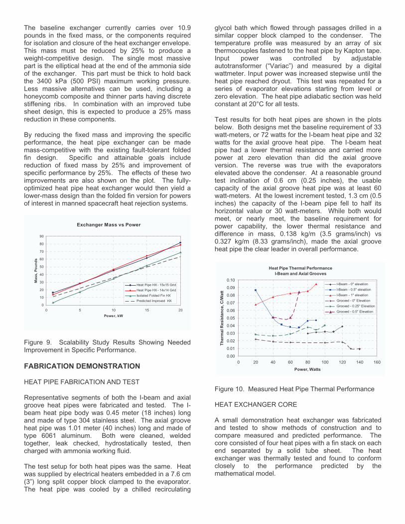
The baseline exchanger currently carries over 10.9 pounds in the fixed mass, or the components required for isolation and closure of the heat exchanger envelope.This mass must be reduced by 25% to produce a weight-competitive design. The single most massive part is the elliptical head at the end of the ammonia side of the exchanger. This part must be thick to hold back the 3400 kPa (500 PSI) maximum working pressure. Less massive alternatives can be used, including a honeycomb composite and thinner parts having discrete stiffening ribs. In combination with an improved tube sheet design, this is expected to produce a 25% mass reduction in these components.
By reducing the fixed mass and improving the specific performance, the heat pipe exchanger can be made mass-competitive with the existing fault-tolerant folded fin design. Specific and attainable goals include reduction of fixed mass by 25% and improvement of specific performance by 25%. The effects of these two improvements are also shown on the plot. The fully-optimized heat pipe heat exchanger would then yield a lower-mass design than the folded fin version for powers of interest in manned spacecraft heat rejection systems.
Figure 9. Scalability Study Results Showing Needed Improvement in Specific Performance.
FABRICATION DEMONSTRATION
HEAT PIPE FABRICATION AND TEST
Representative segments of both the I-beam and axial groove heat pipes were fabricated and tested. The I-beam heat pipe body was 0.45 meter (18 inches) long and made of type 304 stainless steel. The axial groove heat pipe was 1.01 meter (40 inches) long and made of type 6061 aluminum. Both were cleaned, welded together, leak checked, hydrostatically tested, then charged with ammonia working fluid.
The test setup for both heat pipes was the same. Heat was supplied by electrical heaters embedded in a 7.6 cm (3”) long split copper block clamped to the evaporator. The heat pipe was cooled by a chilled recirculating
glycol bath which flowed through passages drilled in a similar copper block clamped to the condenser. The temperature profile was measured by an array of six thermocouples fastened to the heat pipe by Kapton tape. Input power was controlled by adjustable autotransformer (“Variac”) and measured by a digital wattmeter. Input power was increased stepwise until the heat pipe reached dryout. This test was repeated for a series of evaporator elevations starting from level or zero elevation. The heat pipe adiabatic section was held constant at 20°C for all tests.
Test results for both heat pipes are shown in the plots below. Both designs met the baseline requirement of 33 watt-meters, or 72 watts for the I-beam heat pipe and 32 watts for the axial groove heat pipe. The I-beam heat pipe had a lower thermal resistance and carried more power at zero elevation than did the axial groove version. The reverse was true with the evaporators elevated above the condenser. At a reasonable ground test inclination of 0.6 cm (0.25 inches), the usable capacity of the axial groove heat pipe was at least 60 watt-meters. At the lowest increment tested, 1.3 cm (0.5 inches) the capacity of the I-beam pipe fell to half its horizontal value or 30 watt-meters. While both would meet, or nearly meet, the baseline requirement for power capability, the lower thermal resistance and difference in mass, 0.138 kg/m (3.5 grams/inch) vs 0.327 kg/m (8.33 grams/inch), made the axial groove heat pipe the clear leader in overall performance.
Heat Pipe Thermal Performance
I-Beam and Axial Grooves
0.00
0.01
0.02
0.03
0.04
0.05
0.06
0.07
0.08
0.09
0.10
0 20 40 60 80 100 120 140 160
Power, Watts
Th
erm
al R
es
ista
nc
e, C
/Wa
tt
I-Beam - 0" elevation
I-Beam - 0.5" elevation
I-Beam - 1" elevation
Grooved - 0" Elevation
Grooved - 0.25" Elevation
Grooved - 0.5" Elevation
Figure 10. Measured Heat Pipe Thermal Performance
HEAT EXCHANGER CORE
A small demonstration heat exchanger was fabricated and tested to show methods of construction and to compare measured and predicted performance. The core consisted of four heat pipes with a fin stack on each end separated by a solid tube sheet. The heat exchanger was thermally tested and found to conform closely to the performance predicted by the mathematical model.
Exchanger Mass vs Power
0
10
20
30
40
50
60
70
80
90
0 5 10 15 20
Power, kW
Ma
ss
, P
ou
nd
s
Heat Pipe HX - 15x15 Grid
Heat Pipe HX - 14x14 Grid
Isolated Folded Fin HX
Predicted Improved HX

The core of the demonstration heat exchanger is shown in Figure 10. Key components include four 12.7 mm (½”) diameter aluminum-ammonia heat pipes with simple cylindrical screen wicks, a 6.35 cm (2.5”) tall fin stack on each end, and a solid tube sheet in the center. The heat pipe construction and spacing and the fin pitch and thickness were selected to be similar to the full-scale exchanger. The exchanger specifications are shown in Table 3.
The solid tube sheet was used to simplify construction of the demo unit and to provide a means of routing thermocouples used to measure heat pipe temperature. Similarly, cylindrical screen wicks without I-beams were used to simplify construction. Although the axial-groove heat pipes had better performance, the cylindrical wick had adequate performance when operated vertically.
Demo Heat Exchanger Design Specifications
Heat Pipes Quantity 4
Diameter 12.7 mm (0.5 in.)
Material Aluminum
Fluid Ammonia
Wick 100 mesh screen
Spacing 1.58 cm (0.625 in.)
Fins Material 3003, 21-F aluminum
Thickness 0.076 cm (0.030 in)
Pitch 3.1/cm (8/inch)
Width 6.35 cm (2.50 in)
Depth 1.58 cm (0.625 in)
Number t k
20
Table 3. Demo Heat Exchanger Specifications
Two different versions were built. The first was dip brazed to demonstrate the selected assembly method. That unit used type 21-F clad aluminum for the fins. An additional wrap of type 718 Al/Si wire was used at the tube sheet joint. The second unit used type 3003 aluminum fins. All of the components were nickel plated and the assembly was then soft-soldered together. Both versions proceeded through final assembly with no problems. The soldered version is shown in Figure 10.
Thermal performance was tested using water on one side and 50/50 glycol/water mixture on the other side. The water loop served as a fixed-temperature heat source and was routed to the bottom of the exchanger. The glycol loop served as a variable-temperature heat sink and was routed to the top of the exchanger. Fluid temperatures were measured by thermocouples mounted in each liquid stream immediately adjacent to each inlet and outlet. Fluid flow was measured using a graduated cylinder and stopwatch. Thermocouples were also mounted to the evaporator and condenser of each
of the four heat pipes. These thermocouples were routed to the outside of the exchanger through holes bored in the thick tube sheets. Pressure drop was not measured. Due to its having just a single row of tubes the expected pressure drop was just 5 Pa, which was too low to measure accurately with available equipment.
The fluid flow rates were chosen to provide the same face velocity as a full-scale exchanger having the same fin stack geometry. Based on similar fluid stream LMTDs and the ratio of core volumes between the demo exchanger and the full-size exchanger, the expected thermal performance of the demo exchanger was 65 watts. The actual performance of this single-row exchanger would be reduced by 30% to 45 watts. The difference is attributed to the performance enhancement obtained by the row effect, or the wake turbulence present in multiple-row heat exchangers. This enhancement is not present in the single-row demo exchanger.
Figure 10: Core (Heat pipes, fins, and tube sheet) of Demo Exchanger Assembly
The thermal test results are summarized in the plot of Figure 11. That plot shows the heat exchanger power over a range of loop fluid temperature differences. The slope of the line represents the heat exchanger thermal
Tube Sheet
Heat Pipes
Fin Stacks
Fill Tubes

resistance. The power was obtained by performing calorimetry on the glycol and water fluid loops. They were shown to agree within 8% over the entire range of test conditions. The exchanger resistance was computed from the average of the two loop powers and the mean temperature difference between the two fluids.
Testing also showed good agreement between the predicted and measured exchanger thermal resistance. After adjusting the model to account for the measured thermal resistance of the screen heat pipes used in the demo exchanger, a predicted overall thermal resistance of 0.201 K / watt was obtained. Due to a construction problem which resulted in one of the four heat pipes pipe not working, the expected resistance of the exchanger would increase by 4/3 to 0.267 K / watt. The measured exchanger resistance of 0.289 K / watt was within 8% of that predicted value. That result validated the ability of the mathematical model to predict thermal performance.
Figure 11: Measured Thermal Resistance of the Demo Heat Exchanger. The Measured Resistance Was Within 8% of the Value Predicted by the Design Model.
CONCLUSIONS
Heat pipe heat exchangers have the potential to serve as a mass-equivalent replacement for existing heat exchangers while providing the additional benefit of double isolation between the two fluid streams. All of the key components of a heat pipe heat exchanger were demonstrated, including heat pipes and a suitable fin stack. Methods of joining were shown as well as one means of achieving compatibility with the heat exchange fluids. A small-scale prototype exchanger was demonstrated and tested. The ability to accurately model the exchanger was demonstrated through
reasonable agreement between performance predictions and the actual prototype exchanger performance. A clear path has been shown to achieve the necessary mass and performance increases. Ongoing experimental and CFD work has shown that the specific performance improvements indicated by the Scalability Study are within reach.
ACKNOWLEDGMENTS
The work described was performed under a SBIR contract NNJ05JB74C. The Phase I technical monitor was David Westheimer; the Phase II technical monitor is Cindy Cross. Gary Adamson of Hamilton Sundstrand provided significant input during the design and trade study tasks as a part of a subcontract performed during the Phase I work, and is currently supporting several Phase II tasks. Mr. Rodney McClellan of ACT assembled and tested the heat pipes and the demo heat exchanger.
REFERENCES
1. G.Y. Eastman, “The Heat Pipe”, Scientific American,
May 1968.
2. Dunn, P.D. and Reay, D. A., “Heat Pipes” 4th ed,
Elsevier Science LTD.
3. Gray, D.L. and Webb, R.L., Heat Transfer and
Friction Correlations for Plate Finned-Tube Heat
Exchangers Having Plain Fins, Eighth International
Heat Transfer Conference, San Francisco, 1986. pp
2745-2750.
4. Z. J. Zuo, J. E. Fale, N. J. Gernert and M. Goryca,
"Heat Pipe Radiator Design, Analysis and
Manufacturing", Proceedings of the 10th International
Heat Pipe Conference, Stuttgart, Germany,
September 1997
5. J. E. Fale, Z. J. Zuo, N. J. Gernert and M. L. Goryca,
"High Power Heat Pipe Heat Exchanger
Development", 1998 International Joint Power
Generation Conference, Baltimore, MD, August 24 -
26, 1998
CONTACT
Mr. David Sarraf is a Senior Engineer at Advanced Cooling Technologies, Inc., 1046 New Holland Ave., Lancaster PA 17601. He can be reached by phone at 717.295.6059 or by email at [email protected]
DEFINITIONS, ACRONYMS, ABBREVIATIONS
ACTS: Active Thermal Control System
y = 0.289x
R2 = 0.9639
0
2
4
6
8
10
12
14
16
0 10 20 30 40 50
Power, Watts
Te
mp
era
ture
Dif
fere
nc
e, K