heat pipe application spacecraft thermal control
TRANSCRIPT
NOV 24
-i U-,' .
TG-922
AUGUST 1967
Copy No. -
Tecbnical Mvemorandumi
HEAT PIPE APPLICATION FORSPACECRAFT THERMAL CONTROL
by D. K. ANAND and R. B. HESTER
ii
~.,w1
THE JOHNS' HOPKiNS UNIVERSITY *APPLIED PHYSICS LABORATORY
Ns~ cdocvun ,% ~", appv 7 ved (w~ pijbk
/~Oo

I
TG-922
AUGUST 1967
Technical Memorandum
HEAT PIPE APPLICATION FORSPACECRAFT THERMAL CONTROL
by D. K. ANAND and R. B. HESTER
THE JOHNS HOPKINS UNIVERSITY s APPLIED PHYSICS LABORATORY
8621 Georgia Avenue, Salver Spring, Maryland 20910
Qptratng undr CoarLct N~w 62 -0604-c with tht Depotrent ot sNow
I ~Tha doajrm, 6Mo be". apprcý, fef pukk

The Jot.n$ ,Op• s UnM•t SayAPPLIED PYvGICS LAI"MD•TOgy
ABSTRACT
A heat pipe is a device which exhibits an extremely high effective
thermal conductivity by means of two-phase fluid flow with capillary circu-
lation.
The primary objective of the experimental program was to determine
I- a suitable method of control for the heat pipe and to establish suitable wick/
r fluid configurations for the various temperature ranges of interest.
t EThe primary objective of the prototype program was to provide
design, construction, testing for verification, and flight hardware speci-
fications of a heat pipe applicable to thermal control of a sp-acecraft or a
spacecraft subsystem. Thus, a thermal design improvement for space-
craft could be proposed; in addition, thermal resistances of heat pines couldV be derived.
I:
- iii-
-- - - . - - - - -

Th. Jo~hn I HOPI-$e UýýVersdy
APPLIED PNUSICS LASONATORVS.Ivor Sptnq, Motylan$
TABLE OF CONTENTS
List of Illustrations vii
I. Introduction I. .
H. Objectives . 3
ni. Description of Tests . 5
A. Experimental Design 5
B. Prototype Design .. 6
IV. Test Procedures 9
A. Expezimental Design . . 9
B. Prototype Design . . 9
V. Test Results 11
"A. Experimental Design . ! 1
B. Prototype Design . 11
VI. Flight Hardware . 17
A. Flight Hardware Performance Specifications 17
"B. Flight Hardware Design Example . 21
VII. Summary and Conclusions 25
Aclmowledgment 27
Appendix
A Effects of Condens,, ) .rameters on Heat PipeOptimizaticn . . . A-1
B On the Performance of a Heat Pipe B-iC Heat Pipe Experiments II C-ID Heat Pipe Experimnents III . D-1E Heat Pipe Investigations E- 1F Two Fluid Control . . . F-1G Heat Pipe Experiments . . G-1
"H Partial Analysis of the Heat Pipe . H-I
- V.
i-

TM Won e~n.U~i.APPLIES PUVSI• LA"3AYOEV
SaIvr SW 0, g. MAryfatd
LIST OF ILLUSTRATIONS
Figure iage
I Experimental Arrangement
2 Variation of Evaporator Heat TransferCoefficient with Pcwer Level 1 12
3 Variation of Condenser Heat Transfer
Coef'ficient with Power Level 13
S- 4 Prototype Bench Test Setup and Relation ofL Temperature Measurements vs Pipe Length 15
5 Prototype Heat Pipe Performance 16
6 Instrumente,! Configuration 18
7 Noninstrumented Configuration 18
8 Heat Pipe Assembly 22
9 Typical Heat Pipe Layout for SpacecraftThermal Control 23
Appendix A
1 Effect of Condenser Parameters on Heat PipeRegime Temperature A-5
Appendix B
1 Sealed Horizontal Pipe for Wick Boiling B-6
- 2 Wick Boiling Heat Transfer Correlation B-1i
3 Temperature Distribution on Heat Pipe B-12
L 4 Heat Flow vs Temperature Difference BetweenAverage Condenser and Evaporation Temperature B-14
-- L - vii-

lký jot*. Ho~k..z Unv-". 1,arrL,. r..T*lS La.qSUW.
IAST OF ilLUSTRA IONS (Cont'd)
Figure Page
Appendix C
1 Heat Pipe Operating at Saturation Temperature of680F (30 watts and 12 inch Condenser) .- 2
2 Effect of Heat Input Variation on Heat Pipe with aConstant Condenser Area (12 inch) and ConstantCondenser Temperature (54°F) (- 2
3 Variation of Heat Pipe Condenser Area with FixedCondenser 'I emperature of 54°F (30 watts in
All Cases) C-- 3
4 Heat Pipe Operation with Valve Open ShowingIncreasing Transient Stages 60 MinutesApart (30 watts and 12 incn Condenser Length) C-4
SValve Mechanism and Resulting Flow Pattern D-2
2 ('rc'-s-Sectional V.ew of Heat Pipe with Various
Size Disks D-2 -
3 Effect of Blockage of Heat Pipe Core on HeatPipe' Operation D-4: it
Appendix E
1 Comparison of "I 1oretical Heat Pipe SurfaceTemperate, res ith Variation in Heat TransferCoefficient 1,
2 Comparison of Theoretical and ExperimentalHeat Pipe Surface Texnperature. . E-7
vii

iJ F
APPLIED PXN'ISc LAUA ATORV IS-tvw Sui-no. M&Vloed
LIST OF ILLUSTRA'TIOINS (Cont'd)
Figure Page
Appendix H
1 Capillary Tube in Static Equilibrium H-2
2 0Pvaporation at the Meniscus H-4
3 Suggested Method of Thermally ConnectingBattery Tube to Base Plate H-1
-x-
1.

The Jehft Ho&kh% tniworsityAPPLIED PUoSaI LABORATORV
S&tvw Spnog. A ,rvud
LIST OF ILLUSTRA YIONS (Cont'd)
Figure Page
A2pendix F
1 System Showing the Heat Transfer Loop F-2
2 PT-Relation of Control and Working Fluid F-3
Appendix G
Heat Pipe with Various Modifications WhenApplicable G-3
2 Normal Heat Pipe Regime with No Control;Ethyl Alcohol as Working Fluid G-3
3 Comparison of Temperature Distribution withEffect of Discontinuous Wick, 1000 - 140OF G-5
.J4 Comparison of Temperature Distribution withEffect of Discontinuous Wick, 1500 - 190°F G-5
5 Interruption of Vapor Flow (Plug with1/4- inch- Diameter Hole) G-6
6 Interruption of Vapor Flow (Plug with1 / 10- inch- Diameter Hole) G-6
Interruption of Vapor Flow (Plug withNo Hole) G-7
8 Heat Pipe with Effects of Fluid Flooding G-7
9 Heat Pipe with Introduccion of Air G-8
10 Heat Pipe Operation at Low SaturationTemperature (1060F) G-8
11 Heat Pipe with Various Modifications WhenApplicable G- 9
-ix-K'__

I. Introduction
A heat pipe is a device which exhibits an extremely high effective
thermal conductivity by means of two-phase fluid flow with capillary
circulation. In simplest form the device consists of a length of
tubing, sealed at both ends, containing an annular wick and a small
el amount of working fluid. Heat enters one end of the pipe (the
evaporator section) and evaporates a portion of the fluid. The vaporthen flows to the opposite end of the pipe (the condenser section)
where it is condensed. The condensate is returned to the evaporator
by the capillary pumping action of the wick.
This study and development work on heat pipe application for
spacecraft thermal control was sponsored by the National Aeronautics
and Space Administration-Office of Advanced Research and Technology
in accordance with APL/JHU letter TS-1343 dated 19 September 1966.
SThis letter was approved by NASA letter RNW dated 10 October 1966
addressed to the Laboratory.
ME
L t
:NA
911

Fit-
SII . Objectives
The primary objective of the experimental program was to determine
a suitable method of control for the heat pipe and to establish suit-
able wick/fluid configurations for the various temperature ranges of
interest.
The primary objective of the prototype program was to provide
design, construction, testing for verification, and flight hardware
specifications of a heat pipe applicable to thermal control of a
spacecraft or a spacecraft subsystem. Thus a thermal design improve-
ment for spacecraft could be proposed. In addition thermal resist-
ances of heat pipes could be derived.
Zi °
Nm

m- Fel al --- M- - -.
III. Description of Tests
A. Experimental Design
To accomplish the objectives, two heat pipes were fabricatedand were subsequently instrumented. The heat pipes are of
stainless steel construction and are provided with valving to
facilitate vacuum pumping and fluid charging. Controllable
resistance heating was utilized to bring heat into the system
"while heat removal from the condenser will be accomplished by
means of a constant temperature bath. Appropriate temperature
and pressure instrumentation is provided to measure heat fluxes
and overall heat transfer coefficients. Insulation is provided
over the evaporator and isotherma: sections of the heat pipe to
minimize heat losses to the atmosphere.
1. Control Techniques
Various control techniques were investigated. These
can be categorized as follows:
a. Regulation of vapor flow.
b. Control of condenser parameters.
c. Introduction of non-condensable gases.
d. Control of the pressure of the working fluid.
e. Regulation of fluid flow through the wick.
Only the first three methods were investigated in detail.
Earlier work at the Applied Physics Laboratory has proved
that heat pipe operation can be effectively stopped by pro-
viding a complete wick discontinuity (item e); however, this
method may not be the most suitable for space applications.
Refer to appendices.
2. Experiments
The following experiments were condicted:
5 -5

*1"
2. Experivents (cont'd.)
a. Vapor regulation: The flow area will be pro-
gressively blocked near the condenser while holding
other variables constant. Curves will be obtained
showing the variation of average heat pipe temper-
ature with percent open area for given heat inputs
and constant condenser parameters.
b. Variation of condenser parameters: Condenser area
and temperature will be varied while holding other
parameters constant. A family of curves showing the
effects of each parameter on system performance will
be obtained.
c. Injection of a non-condensable gas: rhe heat pipe
will be operated with measured amounts of a non-cou-
densable gas injected to determine the effect on
temperature.
d. Wick/fluid configurations: Different wicking
materials, such as stainless steel screen and porous
stainless steel, will be utilized wiich such working
fluids as ethyl alcohol, distilled water and freon.
Operation will be at high, as well as low, temperatures
to verify whether the performance is satisfactory.
B. Prototype Design
Figure 1 is a schematic diagram of the prototype arrangement.
As shown, the major items are the refrigeration unit, the cooling
tank, and the heat pipe assembly. An absolute pressure trans-
ducer, in conjunction with a wheatstone bridge and voltmeter, is
used to measure vapor pressure. Copper-constantan thermocouples
sense temperatures on the outside of the heat pipe and at various
locations within the insulation. These temperatures were auto-
matically recorded by a 24-point recorder.
-6-
Al. -. . .-- - -

I ~Tranaducer
Coolng lfrhigrat ion -
F-

IM
The refrigeration unit is a conatant flow device equipped
S-with two evaporators. The main evaporator is located in the
cooling tank and serves to remove heat from the fluid therein.
An auxiliary evaporator is located within the cabinet of the
refrigeration unit. Temperature control is accomplished by
means of a sensing bulb and a bellows assembly. When thetemperature of the liquid reaches the control sett:'ng, a
solenoid valve is energized, diverting the refrigerant from
the main to the auxiliary evaporator.
The cooling tank is filled with a mixture of water andantifreeze. A specially-designed split seal fastens to thecondenser end of the heat pipe and to the wall of the tank to
maintain water-tight integrity. The tank is insulated on all
sides to reduce heat leakage.
At the evaporator end of the heat pipe assembly, a re-
sistive heating coil, wound on a hollow aluminum cylinder, is
used to supply hi-at to the pipe. Power to the coil is fur-
nished by a DC power supply which has suitable controls to vary
the power as desired.
- -

IV. Test Procedures
A. Experimental Design
(Refer to appendices)
B. Prototype Design
Calibration ol the absolute pressure transducer was
accomplished prior to filling the heat pipe. Briefly, the
procedure was to evacuate the pipe with a vacuum pump and
balance the wheatstone bridge. Next, the vacuum pump wasi removed and the pressure was allowed to equalize with the
atmosphere. The voltage and atmosphere pressure were re-
corded and a linear relationship was assumed to hold. This
correlation was checked at several other pressures during
the normal course of atmosphere pressure variation.
After filling and sealing, the heat pipe was instrumented,
insulated, and the condenser end iaserted into and sealed to the
cooling tank. The refrigeration unit was energized and set to
a prescribed level. The heat input was then adjusted by means
of the power supply and the electrical input measured. Pressure
and temperatures were recorded until steady state conditions
were attained. The heat input level was then changed while
holding all other parameters constant. To verify that the data
were repeatable, certain runs were conducted again after an in-
terval of a few days.
I _oi!

The jdW Moshwqs U.k*aehV
SOV" swift. MA"yI&d
V. Test Results
A. Experimental Design
(Refer to Appendices)
B. Prototype Design
To correlate the data, an overall heat transfer co-
efficient, U, is defined by:
q = UAAT
where AT = the difference between the me~awall temperature of the evaporatoror condenser and the fluid
A = the heat transfer area
U is thus seen to include conduction as well as con-
vective effects. A dimensionless heat transfer coefficient,
is then calculated and correlated with a dimensionlessheat flow, q-, where:
= SATgDe
and S = entropy
= absolute viscosity
De - equivalent diameter
Pr Prandtl number
Figures 2 and 3 show this correlation for the evaporator
and condenser of the heat pipe tested. The curves are
typical of convective heat transfer data and substantiate
the choice of correlation.
- 11.-

[Er M
I% Jolws I• oakt Unfww.tyAPPL'ES PHYN¥SOS" L te*v
-j
S4 IILo°u
IL-1 .5
1z. 2.5 4 6 •01
z
II
1 .5 2.5 46 8 0 15
RELATIVE POWER LEVEL, - x 103qo
Fig. 2 VARIATION OF EVAPORATOR HEAT TRANSFERCOEFFICIENT WiTH POWER LEVEL
L
-12- [

S":. •the) Johns Hopkins University
APPLI9D PHYSICS LASS. TORY
SIver Sp-ng., Ma'ylwd
2.5 __
1z
1.0U.
W 0.0000- _ _ - - _ _ -
IL0u 1.0
". 0.8
•, 0.6 -
',A)-lu 0.4
-- 0.25 ______ _______ ___
ziw
"0.1 I
0.1 0.2 0.3 0.5 0.7 0.9 1.5 2.5 4 6"• •;_.RELATIVE POWER LEVEL, qX 103
S~qo
Fig. 3 VARIATION OF CONDENSER HEAT TRANSFERCOEFFICIENT WITH POWER LEVEL
c
tit-13- I_

i I41
To calcelate the thermal resistance rt a given heat7-
flux, consider the analogy between the expression defining
U and Ohm's law:
q = UAAT A
E L
The emf, E, corresponds to AT and the thermal resistanceSis thus R a Te The thermal resistance of the isothermal
section of the heat pipe is negligible. Hence, the totalresistance of the heat pipe consists of the series resistances
of the evaporator and condenser:
Rp= Re Rc=+le + I I-I
For comparison, the thermal resistances of lengths of
pure copper bars of weight equal to that of the heat pipes
were calculated. The resistance of a thermal conductor is
given by-
SLL R
where L is the length and K is the thermal conductivity.
At a heat flow of 100 BTU/hr., the relative resistances
of the heat pipes and copper bars are:
Rcu = 27.6 for an 18" heat pipe
p
F Rcu = 58.2 for a 38" heat pipe
P
- 14 -

To summarize, Figures 2 and 3 present data correlations in
dimensionless form. Using this data, the thermal resistances of the
two proposed SEOS-B heat pipes were calculated and compared to the
resistances of lengths of pure copper of equal weight. For a power
level of 100 BTU/hr., the thermal resistances of the copper bars
were about 28 and 58 times that of the short (18") and long (38") heat
pipes, respectively.
Figure 4 below indicates the prototype bench test setup and
relation of temperature measurements vs pipe length. The prototype
heat pipe performance is shown in Figure 5. Varying power heat in-
puts are shown on each curve.
Fig. 4 PROTOTYPE BENCH TEST SETUP AND RELATION OF
TEMPERATURE MEASUREMENTS VS PIPE LENGTH
HeatInput Isothermal Condenser
/Section
[ /Water Temperature
Exterior of em tr Exterior of Heat7(empeaturePipe WallHeat Pipe Wa paverage
SI I I
I i radient
Temperature
51
S- Jar

il i t
i OW-wI~3 U U
1 1 2

* ~ APPUIS PUWOSO LASeAISOV
VI. Flight Hardware
A. Flight Harlware Performance Specification
1.0 S~cope
This specification delineates the performance require-
ments, inspection and test procedures and qualification
for flight of heat pipes for the spacecraft.
2.0 Applicability
Provisions of this specification shall apply to proto-
type and flight units in both the "instrumented" and"non-instrumented" configurations. In the "instrumented"
configuration the heat pipes are equipped with absolute
pressure transducers. In the "non-instrumented" con-
figuration, the pressure transducers are removed, the
center tube crimped and welded and the protective cap
installed and welded to the boss. (See Figures 6 and
7.)
3.0 General Requirements
3.1 Initial evacuation, filling and sealing of the
heat pipes shall be accomplished with a minimum
of air leakage into the pipes. The maximum per-
missible air volume for the heat pipes shall be
that volume which results in a partial pressure
due to air of 2 mmfig per inch of length at a
temperature of 70 0 F.
3.2 There shall be no additional leakage of air into
the heat pipee while in the instrumented configura-
tion.
3.3 The heat pipes shall be designed to operate satis-
factorily throughout the useful life of the
"satellite. A failure of one or both heat pipes,
"- 17-
1iua

transducer
Fig. 6 INSTRUMENTED CONFIGURATION
protective cap
.- eldboss
Fig. 7 NONINSTRUMENTED CONFIGURATION
-!8-
am

"LOSO PvuS1o L"SAo&TUAV
3.0 General Requirements (Cont'd)
3.3 however, shall not be deleterious to satelliteperformance.
4.0 Performance
4.1 The heat pipes shall exhibit an effective thermal
conductivity of at least 2,200 BTU/hr ft *F over
an operating range of from 0OF to 1300F. The
effective thermal conductivity shall be calculated
using temperatures measured on the exterior of
the pipe. Temperatures measured at locations
closer than two inches from the end of the evapo-
rator section or from the beginning of the con-
denser section shall not be used for this calcula-
tion.
4.2 The heat pipes shall transmit up to 30 watts of heat
over a temperature range of from 00F to 1300F at
the specified effective thermal conductivity.
5.0 Inspection and Test
5.1 Prior to evacuating, filling and sealing, the heat
pipes shall be subjected to pressure and leak tests.
The heat pipes shall withstand a pressure of 125
psig of dry nitrogen gas without leakage for a
period of 30 minutes. Following the pressure test,
the pipes shall be subject to a helium leak test.
There shall be no detectable leakage.
5.2 Bench testing of the pipes in the instrumented
configuration shall be accomplished after thepressure and leak tests. The pipes shall meet
Sall requirements specified in Paragraphs 4.1 and
4.2.
-19 -
I.

Sam uAR. MmWB iA*i
5.0 Inspection and Test (Cont'd)
5.3 Bench testing shall be accomplished by utilizing
equal areas for the condenser and evaporator.
Resistance heating shall be used for the evapora-
tion of fluid while a controlled temperature bath
will be used as a heat sink. The heat pipe shall
be appropriately insulated. Instrumentation shall
be provided to measure the temperature distribution
along the outside of the heat pipe as well as
losses to the atmosphere. For each run the power
level and the heat sink temperature shall be
maintained constant. When steady state conditions
are attained, the experimental parameters may be
changed and a new run began.
6.0 Qualification for Flight
8.1 After the completion of the tests specified inParagraphs 5.1 and 5.2, final crimping and sealing
shall be accomplished. The effective thermal
conductivity shall again be measured as per Para-graph 4.1 at power levels up to 30 watts. A
degradation of effective thermal conductivity of
as much as 5% of the original value is permitted.
6.2 VibratioL tests shall be conducted on the heat
pipes at the frequencies and amplitudes specifiedin the Design Data Sheets. Following the comple-
tion of the vibration tests the effective thermalI conductivity shall again be measured. A degrada-tion of 1/2% of the value as measured during the
tests of Paragraph 6.1 is permitted.
6.3 Thermal vacuum testing shall be accomplished with
the heat pipes installed in the satellite in a2-
cordance with the applicable Design Data Sheets.
- 20 -

The jaiw ""Alm~ URKWSty£APftSOI PymV LAUEA•*NV
"VI. Flight Hardware (Cont'd)
B. Flight Hardware Design Example
Figure 8 presents an example of a spacecraft heat
pipe design assembly while Figure 9 shows a typical lay-
out for electronic package connection.
21
IT

U)U
Smi c'o'
I
w
22i :2C/
2.._ _ _ _ _
S- 2•.

4>
4'-
I2 0

U
V E VII. Sumuary and Conclusions
The test results for both the early experimental work and
prototype effort show excellent correlation as to performance
and control of a heat pipe design. The data also clearly dem-
onstrates its proposed use to provide thermal control in a space-
craft application.
*25
L
I
1|~
L
V.- 5
PkkCE1PAL-LN

1ho Johns Hopkins UntivittsiyAPPLID PHYSICSl LAIBONATOOVy
ACKNOWLEDGMENT
AcknowK,•dgmernt is made to R. Harkness and R. E. Fisehell (APL)
for developrtent effort of the prototype heat pipe; R. Willison, G. C.Weiffenbach, C2. Wingate, S Willis, A. Reymarmn (APL) for their
analysis and design reviews of spacecraft applicationz; and to T. Wyatt
(APL) for suggestions and comments throughout the subject effort.
i- - 27 -
t[

-W• VI*, U LAOW v Appendix A
EFFECTS OF CONDENSER PARAMETERS ON
HEAT PIPE OPTIMIZATION
C byD. K. AnandI
A. Z. Dybbs 2
R. E. Jenkins"
N
SiStaff Engineer, Space Power Thermal and Attitude Control Systems: ['heJohns Hopkins University, Applied Physics Laboratory.
[ 2 Research Fellow, Department of Mechanics*Engineering, University ofPennsylvania, PhiJadelphia, Pennsylvania.
3 Engineer, Space Analysis md Research, The Johns Hopkins University,C• Applied Physics Laboratory.
-A-1-II

APP1fl PHYUM LASSUATOOY
5d we elas. MWatW Annpnti4v A
EFFECTS OF CONDENSER PARAMETERS ON
HEAT PIPE OPTIMIZATION
In most applications of heat pipes the maximum heat transport is
dependent upon liquid circulation due to capillary forces in the wick. For
a specific capillary structure the local pressure difference must be
pv(z) -pA(z) r 2Ocos r (i)c
where the equality would yield maximum heat transport. Foi' low Reynolds number
Re, substituting the appropriate pressure drops,1'2 Eq. (1) beccmes
4 4v(te + L)Q w t(L + Ae) Q°"e 2 a cos C+ 0 , (2)n p , r4 2r(r w r v)p, er 2 c(
for riaximum heat transport. Here r is equal to the inner radius of the heat
pipe (r.) minus the thickness of .the wick; i.e., it is the inner radius of
the wick. Optimum values for r and r can be obtained from Eq. (2), allc v
other properties being fixed. The value of r that would maximize Q isc
determined from bQ/ar = 0, where Q is defined by Eq. (2). This value whenc
resubstituted into Eq. (2) yields
2 ~ 2vp,L -a cos•e=o (3)
v e) vrr -r ) cos
r i*
i - A - 3 -
PRE r~UPAGE Bt
Rm

IAppendix A
It is clear that the maximizing of Q now requires the evaluation of 6Q/•r = 0.2V
This constraint yields (r /rw) 2 = 2/3 which when substituted into Eq. (3) will
yield
2 TT r3 X cCose e PvP 1/2()
3(L+ be) (4)
Under steady state conditions, the heat Q transferred through ther
condenser may be denoted by [k T D(Tv - To)/In - L where K,D,AT,L are theV 0 r v
effective conductiity, heat pipe diameter, radial temperature drop from inside
to outside aurfa'e, and the condenser length respectively. This Q may also ber
written as CL where C becomes (k r D A T/ln 02). Substituting L = Q/C into
Eq. (4) leads to a quadratic in Q, which yields the solution
Qot/ C yrw X O C2 LA2 112 " C e/12 (5)optmu 3+1 9r C we e
From Eq. (5), it is seen that the operation of the heat pipe, Is constrained
chiefly by condenser parameters. Extensive experimental data obtained at the
Applied Physics Laboratory bears this out. Figure 1 shows the "heat pipe
regime" temperacures as a ftuiLtion of the condenser parameter C. The experi-
mental data is for tfe following heat pipe.
That seipentc of the heat pipe over which the tem'erature drop of the vapor issmall, of the order of l-2°F. This segent consequently exhibits very highthermal conductivity.
• - A-4-

z w0r~ X Z
ILw
00m C)j
*~ U N
0 0~ 0Z WgW IL
X OO0-:o.4OF1
bin.
0l IL VIILd
-
____ a ý

i- Appendix A"run~l eollen tLeA"""
(r- y) = 0.063 inchej
e = o.68
rr - 0.815
r = 3.25 x 10"3 inchesC
Q =30 watts
w= 15
fluid = ethyl alcohol
.The optimum heat transport that could be achieved is 725 watts with 0.1 effective
conductivity, 600 contact: angle, 1.5592 x 10 3 ibf/ft surface tension and a
radial temperature drop of 200 F across condenser surface. The condenser surface
area required is 5 square feet. The variation of condenser parameter C may be
achieved by flooding, introduction of noncondensible gases, or manually varying
surface area. The reported data is achieved by flooding and varying surface
area. The effect of noncondensible gases is similar although more dramtic.
The above comments are based on nonradiative type condensers. in
applications where the heat is radiated away from the exterior surface of the
condenser, an interesting situation may develop. We have given the name
"temperature choking" to this effect and offer the following explanation.
The equilibrium temperature of the vapor (and consequently the evaporator
section) for a given power dissipation is determined by the temperature of the
outer surface of the condenser. For radiative condensers the equilibrium
equation becomes
- A-6- 4
#,4
I.

" .,Appendix A
4 4F A c(T - T)= L k D(Tv -To)/ln ro/r (6)
Now, since the heat is removed from the outer surface by radiation, there is
no longer a strong boundary condition on the temperature .f the outer surface
as there is in the case of a condenser bath. Consequently, th- outer tempera-
ture will adjust itself so that in equilibrium the heat radiated equals the
heat input. If the heat flow through the condenser is increased, the temperature
"of the outer condenser surface must now increase to radiate away the extra heat;
and since the temperature difference across the composite condenser wall determines
the heat conducted through the wall, the temperature of the vapor core must increase
F even more. Thus, the temperature response of the vapor to heat flow increases
should be quite different in this case from the case of a condenser bath, where
bath temperatures may be irndependently varied.I -o
"From a design viewpoint, this requires high C values in Eq. (5).
- A-7 -
bi-r
I

*a JA __ Appendix AAPLMUS INV LIA19"UU
S•Nomenclature
C = condenser parameter, k n D(Tv - T )/ln r /r BW/hhr ft
D = heat pipe diameter, ft
e = porosity of wick, (pf - P )/Vf
F = radiation shape factor
-= length of evaporator, ft
L = length of condenser, ft
Re = Reynolds number,
p a pressure, lbJsq. ft 2
Q - heat flow, BTU/hr or watts
r = radius, ft
T temperature, oF
V = velocity, ft/sec
z = axial heat pipe coordinate
w = constant, properey of wick, due to the tortuous path taken by fluid
flowing through the pores. Varies between 8-20
e = contact angle of fluid, radians
A latent heat of vaporization, BTU/lbm
2= coefficient of viscosity, lbf sec/ft
p = lensity, lbJft3
a = surface tension, lbjft
Subscripts
a = ambient
c = wick pore
f= fluidS- ~A-8-

I- Appendix AIi. • l~w~ol P'S.II IAO•
Subrcripts I.Cont'8d)
A = liquid
j ~v = vapor
v = wall, inside
0 = wall, outside
at
I-
Ip
I
IIL

S• • .Appendix A
Acknowledgement
This work was supported by the National Aeronautics and Space
Administration Headquarters, also the Naval Air Systems Command, Department
of the Navy under Contract NOw 62-0604-c.
- A-IO -

- -.
Im im" WakuUWW~hvAppendix A
References
1. Cotter, T. P., "Theory of Heat- Pipes," IA-3246-M&, Los Alamos ScientificLaboratory, Loa Alamos, New Mexico, Z1965).
2. Anand, D. K., "On the Performance of a Heat Pipe," Journal of Spacecraftand Rockets, May 1966,
A
[

Appendix B
ON THE PERFORMANCE OF A HEAT PIPE
D. K. Anand*
I • Space Development DivisionThe Johns Hopkins UniversityApplied Physics Laboratory
i -17
*Also Assistant Professor of EngineeringUniversity of Marylandr : College Park, Maryland
-B-1-

A.pencix B
NOMENCLATURE
A M Area of wick, ft 2
C W Specific heat, BTU/lb. 07i2
D - Diameter, ft 2
g - gravity, ft/sec
h - boiling heat transfer coefficient for wick - Q/A(Tv-Tw)
K - thermal conductivity, BTJ/ft. hr. OF
L - Length, ft.
Np - Pressure number
Pr - Prandtl number - Cp/K
p - pressure, lb/ft2
Q - heat, BTU/hr.
Re - Reynold number -pvD/p
r M radius, ft.
St - Stanton number - h/cw - 9 PraNpbRec
T - temperature, OF
v - Velocity, ft/sec
w - Mass flow rate-- Q/Ak,, lb/sec.
X - Axial direction of heat pipe
, - Constants
9- Porosity of wick -( - pr iP - Density, lb/ft
9 - Viscosity, lb/hr.ft.
S- Latent heat of vaporization, BTU/lb.
0 - Surface tension, lb/ft.
IB

Appendix B
SUBSCRIPT91
I - wick fiber
4 - liquid
p - pore in the wick
v vapor
w - wall
wi - wick
B-

Appendix B
INTRODUCTION
The requirements of cooling in the space environment
have led researchers to study various coolants and high thermal
conductivity devices. The heat pipe described in this note (Fig. 1)
is a self-contained device that exhibits a very high effective thermal1
conductivity. It consists of a sealed tube with wick material in
contact with the internal heat transfer surface. The operation is
based'on the evaporation of a liquid in the evaporator section and
subsequent flow in the core towards a region of low pressure. In
the condenser, the liquid is condensed and flows back to the evaporator
through the wick by capillary pumping to continue the cycle. Under
steady state conditions the pressure in the evaporator section is
* slightly less than the vapor pressure of the adjacent liquid, thereby
assuring continuing evaporation. In the condenser section, the opposite
holds, assuring continuing condensation. Owing to this liquid-vapor
interface, the radius of curvature of meniscus in evaporator recedes,
and that in the condenser increases. In the condenser, especially if
there is excess fluid, the radius of meniscL nay be infinite
The transient behavior has not been studied extensively,
but it would seem that this phase will not present any great difficulty.
It is clear, however, that there will be an upper limit to the heat
flow through the pipe, because liquid depletion rate in the evaporator
must exceed the recirculation rate by capillary pumping.
-
-B-5

Appendix B
sof
LI Z
SIU.Z
aa
z-
s.J
- - Ii I
-O- z
4c0I to1 . ' 4
B-6a

I
DYNAMIC OPERATION
The heat pipe comprises two domains: The vapor core and
the fluid annulus (fluid flowing throagh the wick). The flow conditions
in these regions merit separate attention. The vapor flow in the core
is similar to flow with injection or suction through a porous wall,
since a liquid and vapor are continually changing phase at the inter-
face. Cotter 4 has explained the dynamics of vapor flow and we largely
use his explanation here.
Several different vapor flow regimes may be obtai.ned
based on the Reynolds number reierred to the vapor core diameter.
For Rev<< 1, the velocity profile is parabolic and flow is similar
to Poiseuille flow. The pressure decreases in the direction of flow
with a gradient larger than that of Poiseuille flow in evaporation
and smaller in condensation. Flow properties are obtained using
constant Rev; for almost all cases of present interest this is justified.
For Rev<<l, the velocity profile is no longer parabolic, but vapor
pressure still decreases in flow direction, and the properties of flow
may still be obtained as above.
For Rev = constant <<l the pressure is3:.dp/dx -f (8 pWvijPr 4 ) (I + 3 Rev + .. 1
4 v
Since this drop is small, the firsx term usually suffices for determin-
ing the pressure drop. It is appropriate to remark that the temperature
drop may be obtained using the Clausius-Clapeyron equation.
The liquid flow through the annulus is quite different from
the core. The momentum equation for incompressible steady flow is:
2VP Pg + A& v - PvAv (2)
-- B-7

I
Appendix B
If an average velocity (v) is defined over an area of wick which
includes the solid structure, then the velocity within the pore is
(v)/e, where e is the wick porosity. Observing that the velocity
*i on the pore surface vanishes and is of the order (v)/c within the
passage, the following approximattons may be made:
2 2 22pvVv-.- P(v)2/ re2, pV v-- & (v)/ er 2 (3)
Since (v) is small, equation (2) becomes?2
Vp p pg + V. 2v (4)
and the ratio of the two expressions in (3) yield a liquid Reynold
number based on (v). Although the last term is neglected in the
expression for the pressure drop, this Re. will be used in the
performanse correlation; experiment shows that indeed Re <<l.
From equations (3) and (4) the pressure drop for a horizontal pipe
becomes
2 r2 2-ApM w- QX/2(r - r) per L (5)
w v p
where w is a constant depending upon the capillary structure. The
vapor pressure drop has also been computed from equation (1) consider-
ing only the first term and is
4Ap -4pQX/wPr L (6)
V v
It is assumed that the region between the condensing and evaporator
section is perfectly insulated and that Rev<<l.
--
S! -B-8 -

Appendix B
CORRELATION AND EXPERIMENTAL RESULTS
As an extension to the above study, one can correlate the
heat transfer coefficients in the evaporator section and thereby obtain
a rather good indication of the engineering performance.
Since the problem is essentially that of wick boiling and
condensing, in the evaporator and condenser, dimensionless analysis
applied to this problem yields
St- prNpRe (7)
where the properties for evaluating the numbers are that ef the fluid.
The correlation by these relations and its subsequent conparison with
pool boiling heat transfer coefficients show the desirabllity of wick
boiling at low Q and Re.
Experiments have teen performed to show the temperature
distribution, the bciling heat transfer coefficients, and the vapor
temperature and pressure drop. The experimental set up consisted of
a 3 in. O.D. stainless steel pipe 24 to 36 in. long, with its
"interior wall covered by a wick material (Fig. 1). The wick used
was a passivated, lO0-mcsh stainless steel screen with porosity
varying from 0.65 to 0.94. Heat was added at the evaporator sect'on
Sby resistance heating. The entire pipe was insulated using polyurethane
foam. The condenser seution was kept in an ice bath. Temperatures
were measured using a 24-point DaystrOm recorder during transient and
steady state operation.
The experiment was started by placing the tube in a vertical
position and boiling off water in order to evacuate the tube of air and
non-condensible gases. When there remained enough water to saturate
it I1389 -[,_

the wick and a very small excess, the tube was sealed and placed in
2Ia horizontal position. The heat input (700 to 6000 BTU/hr-ft ) was
adjusted to a predetermined value and condenser temperature controlled.
The temperature of the vapor inside the heat pipe was monitored using
a thermocouple c-ibedded in an axial wire.
The wick boiling heat transfer coefficient is h Q/A(;-Tw)
and the liquid wass flow rate is W - Q/Aek. Selecting 0.6 as the
exponent of the Prandtl number, to correspond to liquid heating litera-
ture, the dimensionless correlation is. obtained as
6 1.143 2St - 0.00051 Pr" RC-4 N (8)The above correlation is compared to previous data and shown in Fig. 2.
It is clear from Fig. 2 and published pool boiling data2 that higher
results are obtained at low heat fluxes and lower numbers at higher
heat fluxes. This le 4ds to the confirmation of the idea that wick
boiling ts preferable at low heat fluxes. Presence of the wick
materi'l decreases turbulence near the surface, increases the effective
surface area, and provides active sites for bubble formation, so that
higher film coefficients at low beat flux are obtained compared to pool
boiling. The correlated equation (8) affords some insight into the
behavior of the heat pipe under varying conditions. Although the
reaults were obtained for water, experimentation is continuing to
determine applicability and performance of other working fluids.
The temperature distribution along the heat pipe is shown
in Fig 3. The distribution is for steady state operation and
r indicates high thermal conductivity in the axial direction. The
temperature difference of the valor and the pressure differentials
-- 10 -

Appendix B
to,
5-0
"•PREVIOUS DATA
•S 5- 0
PRESENT WORK
100
10- 4 S i0"3 50"REYNOLDS NUMBER
Fi9.2 WICK BOILING HEAT TRANSFER CORRELATION
-B-II -
• P

Apeni BII
II
z0 IL
aa0
tooilvnvvadu 3*AVII
E Z12 -

Appendix B
were very small. Theoretical values obtained by using equations
from Cotter have shorn this. It is clear that very small temperature
and pressure differences are required to supply the necessary driving
forces for successful operation and that their magnitudes are not
too important.
Fig. 4 is a plot of the heat pumped, in the axial direction
off course, versus the difference between the average evaporator
and condenser temperature. This again gives us some appreciation for
the "effective thermal conductivity" that may be obtained.
Although the condenser section was held constant in out
experiments, later experimentation included its variation. T" rmal
runaway occurred when large quantities of working fluid were trapped
in the condenser thereby tending to deplete the supply in the
evaporator section. The exact effect of other variables in thermal
runaway has not yet been determined.
CONCLUSION
The foregoing results indicate the potential usefulness of
rthe heat pipe. However, a method for actively controlling the device
is needed. This work is being presently pursued at the Laboratory.
It is clear that the type of wick and packing can be varied. The
quantity of working fluid is not too.important, provided that the
entire w*ck is properly wetted with a very little excess. The choice
of working fluid is dictated by temperaturc limitations and 1. For.
extaaple, alcohol has low I but also a lower freezing point than water.
3-1-13 -

IJ
Appendix B
300-
#-too!- !
CL
1m.00-0
00
* am
• a.
100 10 20 30 40 so
Fig. 4 HEAT FLOW VS. TEMPERATURE DIFFERENCEBETWEEN AVERAGE CONDENSER ANDEVAPORATOR TEMPERATURE
-B-14 -

} Appeadi-
The effect of other fluid properties may be deduced from equations
(5), (6) and (8). There is no reason to believe that the pipe will
operate at any preferred temperature although better efficiencies
are obtained at low heat fluxes. The temperature and pressure
differentials that act as driving forces are extremely small a
compared to their absolute magnitudes of T and P.
I -B-15 -

II Appendix B
R91"RENCES i
1. Grover, G.M., et al "Structures of Very High ThermalConductance," Journal of Applied Physics, 35, 1900 (1964)
2. Allingham, W.D., and McEntire, J.A., "Determiration ofBoiling Coefficient for a Horizontal Tube J.n WaterSaturated Wick Material," Transactions ASME, Series C,No. - (1961)
3. Cotter, T.P. "Theory of Heat Pipes," Los Alamos ScientificLaboratory, LA-3246-MS
4. Costello, C.P., and Redeker, E.R., "Boiling Heat Transferand Maximum Heat Flux for a Surface with Coolant Suppliedby Capillary Wicking," Chemical Engineering -ProgressSymposium Series, 59 (1963)
-B-16- "

SlA-173-66r ~ A....A~.4- IM
SUBJECT: Heat Pipe Experiments II
REFERENCES: (1) Anand, D. K. and Dybbs, A. Z., "Heat Pipe Experiments,"memo SlA-156-66 to R. E. Fischell
(2) Anand, D. K., "Heat Pipe Inveetigatio,,s," memo SIA-170-66to W. H. Guier
Experiments at saturation temperatures of 1060? and 170°F have1
been previously reported. The purpose of the present experiments is
to operate the heat pipe at 680F and observe the effect of various control
techniques at this temperature. 1he working fluid is ethyl alcohol and
the heat pipe is identical to that used in the previous experiments.
With aptropriate selection of condenser parameters (area and
surface temperature) the steady state heait pipe operation at 680F is
shown in Figure 1. The effect of varying heat input (from 30 to 60 w&tts)
is shown in Figure 2. Note that the previous condenser parameters are
maintained.
Figure 3 depicts the temperature distributions for varying
condenser areas but a fixed condenser surface temperature. Under these
conditions it is clear that dihe operating temperature becomes a direct
function of the available condenser surface area for ordinary conduction.
The effect of introducing a control in vapor core is shown in
Figure 4. The plot is for the valve in fully c-pen position. It is clear
that there is a pressure drop at the valve and this results in two heat
pipe regimes operating at different temperatures. Note that the overall
-C-1

S
Iithe joim MHookm Unieraty
A"LIES POT6C= LA9ONATO-M¥S.Ivw Swmqg 10.wyt-dAirrii
<i ~I zHEAT PIPEI
0!
U I I I I
4 S I I 'I "Iu ,-
___ I___ __K__ _ _ i___'3- 4 8 12 16 20 24 28 32
PIPE LENGTH (inches)
Fig. I HEAT PIPE OPERATING AT SATURATION TEMPERATURE OF 680 F(30 WATTS AND 12 INCH CONDENSEP)
3- HEAT PIPE u
S< I II "
0- 6mm. IWAT1!.
" 70 ___ ____ __ _ __ _ __3 - 4 8 12 16 20 24 28 32S~PIPE LENGTH (inches)
Fig. 2 EFFECT OF HEAT ?NPUT VARiATION O14 HEAT PiPE -
I ~WITH CONSTANT CONDENSER AREA (12 INCH) AND
[ i ~CONSTANT CONDENSER TEMPERATURE (54° F)
S~~-0C-2 - '
IL,
MIE M

th e Jo i n s H o p &i n s U n * ,• 'lsly
Sd,~$ý., .n MWV*W. Appendix
120 -' F - I It COIDENSER LENGTH
I- I
- " -- a •-a - 3 I N C H
Ito
w I
I I
I II O
AL
70 --_ _ A~~ 12IC
'U- "-- - "------- ____ IA 6 INCHZ 9o
so
I - -_ lk a i- t 1 2 IN C H
: "•70L --4 8 12 16 20 24 28 32 36
PIPE LENGTH (inches)
! :" •Fig. 3 VARIATION OF HEAT PIPE "CONDENSER AREA WITHS~FIXED CONDENSER TEMPERATURE OF 54O F (30 WATTS IN ALL CASES)
-C-3

. h"a Ma Appendtx C
EV#,PORATOR'I 'CONOF.NSER
ILI
'FL
I-_ _ _ _ _ _
IL M m (TRANSIENT)
_L1
0z
110 L .JENT)IL.
X
-i I D
4 a 12 16 20 24 28 32 36
PIPE LENGTH (inches)
Fig. 4 HEAT PIPE OPERATION WITH VALVE OPEN SHOWING INCREASING"TRANSIENT STAGES 60 MINUTES APART (30 WATTS AND 12 INCHCONDENSER LENGTH)
L
C 4 o-

Appendix C
operution is at a temperature higher than that shown in Figure 1. This
is so in spite of the fact that the condenser parameters are identical.
The temperature distribution of Figure 4 is transient. The evaporator
temperature could be decreased if the corerser surface temperature were
decreased drastically.
From these and previous investigations 1 '2 , it is conc.lialed
that the control of conden--r parameters is the most desirable control
technique for satellite temperature control purposes.
C-
I --- 5
LI
S. ........ ... ... . .... ....... ...

S2P-3-05
UJ "B &Appe•ndix DSMA6. Pave= I*IAWYU
SSubject: Heat Pipe Experiments III
References: (1) Anand, D. K. and A. Z. Dybbs, "Heat PipeExperiments,," memo $1A-156-66 to R. E. Fische11,dated 27 June 1966.
(2) Anand, D. K and A. Z. Dybbs, "teat PipeExperiment 11,"1 memo SIA-173-66 to R. E. Fischell,]dated 29 July 1966.,
(3) Privzte discussion with D. K. Anand, A. Z. Dybbs,R. E. Fischell, R. Harkness, aud J. F. Smola
(4) Schlichtln , H., Boundary LayerThoyMcrw
Hill Book Co., First Edition, pp. 18-21, 26-27,S~1955.
:. ~Introduction
: • ~Many different types of control devices and techniques ihave ien tested in an effort to control the operation of the beatpipe.-' Among these techniques was the interruption of vaporflow in the core of the heat pipe by use of mechanical valvesand disks with vart, us size holes. Recently a suggestion,concerning the valving techni'que, was madeO that instead of cutting
:" off large portions of the vapor core,• heat pipe control miAght beaccomplished by only cutting off a small (20%) portion of thiscoare. This proposal was made nn the basis of experiments2 performedwith a valve whose actuating mechanism was a long rod connected
, to an inverted hemisphere as is shown in Figure 1. The purpose• ' of the present experiments was thus to investigate the possibilityS~of using small blockage of the vapor core of the beat pipe as a: ~means of heat pipe control.
S~Experimental Apparatus
The heat pipe used in tese experiments was of the
same type as previously employed.", It consisted of a 42 in.: long, 3/4 in. O.D. stainless steel tube with 6 layers of 1/100 in.i :thick stainless steel mesh. The evaporator section of the beat' :• pipe was 6 in. long and a variable condenser length of 12 in.i was used. Evaporation was achieved by resistance heating (30i [" watts) and condensation was accomplished by circulating cold water
[• ..*,tr the condenser length.
II-1
m I

Appendix D
Inverted hemispbere actuated by rod
Figure 1. Valve Mechanism ind Resulting Flow Pattern
beat pipetubeý
wick opnare&open aradisk
~0
(a) (b)20% open area 50% open area
figure 2,. Cross-sectional View of Beat Pipe with Various Size Disks •
-D-2 -

i. ., • Appendix D"amtae "VOWg &hS6AYSU
!, $m&
Blockage o& the vapor core of the heat pipe wasachieved by employing vtrious disks with symmetric circularholes. These disks were inserted at the entrance of the con-denser section. The first disk (Figure 2a) blocked 80% of theavailable vapor core and the second (Figure 2b) about 50% ofthe core. The third case asted was with no blockage. In allcases the heat pipe working fluid was chemically pure ethylalcohol and the condenser length was 12 in. or 6 in.
Discussion of Results
The resulte of vapor core blockage are shown inFigure 3. In this diagram the average temperature of the heatpipe regime--the length from the end of the evaporator to theentrance of the condenser--is plotted versus the percentageopen area of the vapor core. The plots seem to indicate thatat least for open areas greater than about 20%, there is aninsignificant effect on the operation of the heat pipe. Thisresult was anticipated by the author. 3
It should be noted that the points at 20% open ar a"vapor core were interpolated from past heat pipe experiments.AlthQugh these experiments were operated at higher sAturationtemperatures, the previous results indiiated that there was noperceptible difference in the operation between the 20% openvapor core and the 100% open area. Thus, the present interpo-"lation seems Justifiable.
"=" The difference in the results pre~ented here andthose of Ref. 2 for the valve can probably best be explained
as follows: In the case of the valve the flow is in the directionof the inverted hemisphere (see Figure 1). This would cause apressure drop similar to that observed for any type blunt body. 4
Since the heat pipe operates on or near the saturation pressuretemperature curve the pressure drop would produce a correspondingtemperature drop and hence the possibility of two heat piperegimes as was obtained with the valve.
In conclusion one can say: That two heat piperegimes are caused by the mechanisms necessary to operate avalve and not the valve itself; that the valve opening must bequite small before any type of control can be accomplished; andfinally that if a mechanism for controlling a valve is introducedin the vapor cone, extreme care must be exercised to control pressuredrops.
D
• -D3-3-ii _ _ _ _ _ _ _ _ _

?S
,"Li.tt 0"'181f LAS"nATORYLi-& p. ng, Appendix D
W100
w I
"w 6 INCH CONDENSER LENGTH
1-
S90
U.
0
w
MIs-
uI
12 INCH CONDENSER LENGTH
I 70 -w 0 20 40 60 80 100
.% OPEN AREA OF HEAT PIPE CORE
Fig. 3 EFFECT OF BLOCKAGE OF HEAT PIPE CORE ON HEAT PIPEOPERATION (ALL HEAT PIPES WERE OPERATED WITH 30 WATTSINPUT AND 540 F CONDENSER SURFACE TEMPERATURE)
D-4

SlA-lo-66
no SA Oftm" unWO&VApppendix E
SUBJECT: Heat Pipe Investigations
Experimental. data 1'3 '1 on sodium, ethyl alcohol, and distilled water
heat pipes have been previously reported. Theoretical investigations have
mostly dealt with either pressure gradients or wick boiling correlations.
2Cotter has discussed multifluid and optimal heat pipes. The purpose of this
paper Is to show theoretical surface temperatures and performance as a function
of the heat pipe parameters. The cmparison between theoretical and experimn-
tal temperatures is very good. The operation of the heat pipe for satellite
applications is seen to be constrained chiefly by condenser pax'mmters.
Optimum Conditions:
The total heat transport in a heat pipe may increase as long &a~ the
capillary force can sustain the necessary circulation of the liquid In the
wick. Furthermo~re the prebsure differences at the liquid -vapor interface
m-ust be mintained in order to maintain a continual change of phase. For a
capillary structure of pore radius rc having a liquid with contact angle 0,
the radius of the local meniscus is r /coo 0 and the local pressure difference
/C
must be
pv(z) - lp,(z) 19 2 y coo e/r c()
where the equality would yield maximum heat trans~port. For the case of uniform
heat addition and removal, low radial Reynold number the viscous effects
ill ___________•
E-1
W-MM M

P i
ii 4
predominate and the vapor pressure drop becomes that of Hagen Poiseuille flo-
through a cylindrical pipe. Substituting the pressure drops Eq. (1) becomes
4P(Le + L) Q bpI( le + L) Q 2y coso 0
ve+ - (2) "
T~.r 2Tr(r 2 -r 2 ) pe r 2 c
v r. wVC
for the requirement of maximum heat transport. If turbulence does occur, then
vapor pressure must be determined from the Blasius equation:
Ip_ - 06.65 )" .------ /4 z (3)" VV
The onset of turbrlence occurs when the Reynolds number based on axial flow
(N*) exceeds 1,000. In the problem encountered her- N2 < 1,000 and the
assumption of Hagen Poiseuille flow becomes quite adequate provided NR << 1.
Therefore, considering constant properties, the optimum value of rc from
E.(2) becomea
'c~t(le + L)Q
2 2r'( P e Y e Cos)
This substituted into Eq. (2) yields
c Q2 Ycos o 0(5)
z where cI .py(le + Q)t pv c , 2 bpgl, e + L)/21T PL e X
S- ~-E-2 -
i£

i
I he"vtoq-ft #Jn#W-", Appendix E
4~ 2 2vIt is clear that .aximizing Q requires an optimum value for rv rw -r ). Since
is fixed, for any given case, then-"- Lr rr - r) = 0 yields the constraint2 2 2v
that rý/rw Substituting this and the expression for optimum r, the
maximum heat transport becomes
7 r3 X -f Cos P eQ 3 v (6)
If the operation of the heat pipe occurs at high NR, the vapor pressure drop
has been shown to be 7
dpv sia din
dz 4 -d-.v rv
or I 1-k Q 2 k
TT2-- 4 x2 (7)Ap = -8 pv re
4
where s = 1 for evaporation and 2 for condensation.
Since Apv is not a function of the capillary pore size it plays no role in the
determination of optimum rc. Also since it is a function of r 4 (as Ap. forc V
Hagen Poisevile flow) the value of jw sill 2/3. Therefore, substituting
Eqs. (4,7), v-- = 2/3, and ApL from reference 4 into Eq. (I), the optimum Q
becomesI-I
pe Y-cos4 24n 2 YCOS(8)3~- r )
+ le
f" _Q

r"how W iA;,uaw Appendix E
This then represents the !rAximum heat transport achievable for any specific
case. It is, of course, a requirement that appropriate cordenstr areas be
available for the maximum axial transport to leave by ordinary conduction.
For steady state conditions, the heat transfer through the condenser
section must be
rQ 2Tr Lk 6T n = c L (9)
under the assumption of uniform surface temperature. The constant c3 is
defined by the above equation and k is the effective thermal conductivitye
Substituting for L in Eq. (6)
co Q - Pc PAe[c3 e w 3 vA
or
Qoptimum=[crXcs( Cj r~.)*2L] (10)3 .' b 3 e
If .»>> 1, Eqs. (8) and (9) would yield optimizz conditions. Depending upon the
specific problem, constraints could be imposed on the heat flow or physical
parameters, but often not on both.
The experimental temperat "re distribution reportedS was for a heat
pipe with the following parameters:
-E-4-

TI
1I
I • •,• •,•Appendix E
W MWOWj SDO-2039
(rw r) 0.063 inches
o 0.68
r r/rw =0.815
r. = 3.25 x lO"3 inches
"= 30 watts
b =:15
Fluid = Ethyl Alcohol
The optimum heat transport that could be achieved Is 725 watts with a condenser
area of 5 sq. ft., 0.1 effective conductivity, 600 contact angle, 1.5592 x 10⁻³
pound force per foot surface tension, and a temperature drop of 200 F It is
clear that limiting conditions of the heat pipe, in satellite applications,
may be primarily due to condenser paramters.
Surface Temperat-are
An energy balance on a differential element of the heat pipe wall and
saturated wick under steady state conditions yields
at a2t-Ac dx + p0 h0(t - t) •
.i t - t d_ A (11)
or
k A .at (Po ho p ,P h') t + (o h t + p hi ti) 0
:: ,• -E-5-
?

[II
mthi u-igAppehdix X
The temperature at x * 0 is t and at x - L it is t. hese temperaturesVV
refer to evaporator and condenser temperatures and are maintained as constant.
Substituting the boundary conditions and noting that ti is the
vapor te.Apersture which in constant (0. 75P drop in a sodium pipe)' in the
heat pipe regitm, the temperature distribution becomes:
II lmIZ eI(-)e-1'IVt, -.L)L Le(I~ U2 emCth +(tL _3.).~-( ~
M(12)
where:
I Poho0 to + pihi tik Ae C
2 p^ h + Pi h
ke Ac
and ke is the effective thermal conductivity between surface and vapor-liquid
interface, ho and hi are outside and Inside convective heat transfer coefficients,0
Po and Pi are outside and Inside surface perimeters, and Ac is the cross section-
al area through which conductive heat transfer occurs. For insulated surfacesh is very small and the parameter of interest becoes pi hi/ke A0 . This is
0A
Identical to that used for studying performances of extended surfaces. For a
3/4" stainless oteel pine the surface temperatuxe is shown as a function of
length with hI as parameter in Figure 1. It is clear that higher values of hi
ten•d to decrease the effective condenser area. A higher value of hi usually
Implies hioher heat inputs which means that as Q is varied appropriate variations
In the effective codenser area are desirable.
-E-6-

__~~~~~~M - r-- ---- ..
[ ! >
tho Johms oo.•mt Un,ýemlv
APILIEO PHYSICS LABORATORY
Sp s,.ng. Ml,•Apr evdix E
- i120 1 -
110IlCA , I I
2 00 4..- •A
Uj 90<. h = 1 BTU/HRFT 2 -F
, i h= 2.5 BTLI/HR- FT 2 - OFA h = 5 BTU/IR- FT2
-OF
80
70 L IO 4 8 12 16 20 24 28 32
LENGTH (inches)
Fig. 1 COMPARISON OF THEORETICAL HEAT PIPE SUPFACE TEMPERATURESWITH VARIATION IN HEAT TRANSFER COEFFICIFNT h
_110_1 _
CL,
S C RU 1 SATUAT TALEM T
- 0 20121.6I
Ig C THEORETICAL V ALUEP
SURFACE TEPRAUE (160FPATRAMETION VATEMPRTUE
0i 5 B0H FT 2 _6 OF)
S; :. E-7 -

_ Appendix E
Figure 2 shows a plot of the theoretical and experimental temperature3
profiles in the heat regime for a saturation temperature of 1060 F.
Both the optimum performance and the temperature distribution confirm
Sthe opinion that the control of condenser parameters is apparently th• k-ti to
controlling the overall performance.
Ncmenclature
A area square feet
b constant
e porosity of wick
h heat tranafer coefficient of convection, BTu/hr sq. ft.
A length, ft.
L length, ft.
N Reynold number = 2p rv/A
p perjrter, ft.
p pressure, ib/sq. ft.
Q heat flow, BTU/hr.
r radius, ft.
t temperature 'F
v velocity, ft/aec
z axial heat pipe coordinate
y surface tension, lb Ift
8 contact angle of fluid, radians
X latent heat of vaporization, BTIJ/Ib
4 coefficient of viscosity, lbf sec/ft2
P density, lb /ft 3 .
1.

is& ""hi Upkt Appendix E
Subscripto
c wick pore
c cross-sectional ^rea
i inside
t liquid
0 outside
R radial coordinate
v vapor
V wick
z axial coordinate.
IE _

References
1. Grover, G. M., T. P. Cotter, and G. F. Erickson, "Structure of very Highb.ermal Conductance," J. Appl. fhoaice, 3, 31990 (1964).
2,. Cotter, T. P., "Theory of Heat Pipes," March 26, 3.965, Los Alamos Laboratory,
New Mexico.
3. Anand, D. K., A. Dybbs, "Heat Pipe Experiments," SlA-156-66.
4. Anand, D. K., "On Heat Pipe Performance," ARS, May 1966.
5. Alling~ham, W. D., and J. A. McEntire, "Determination of Boiling Coefficientfor a Horizontal Txige in Water Saturated Wick Material," Traiw. ASNE, Ser. C,No. 1 (-961).
6. Grover, G. M., J. Bohdansky and C. A. Busse, "The use of a New Heat RemovalSystem in Space Thermionic Power Supplies," Euratom.
7. Knight, B. W., and B. B. McInteer, "Laminar Incompressible Flow in ChannelsI with Porous Walls,"' LADC 5308.
8. Jakrb, M., "Heat T"1r•sfer," Vol. 1, John Wiley and Sons.
II
~E-10Q-

SlA-161-66W PftS ft U• • woty Appendix F j
SUBJECT: Two Fluid Control
REFERENCES: 1. Anand, D. K., and Dybbs, A., SlA-156-66, dated 27 June 1966
2. "Mechanic,3. Engineering,' ASM, March 1966, page 71
Introduction
II
Three of the previous techniques reported, for controlling the
heat pipe, involved a fixed amount of working fluid in the main heal
transfer loop. One technique required condenser flooding, but the fluid
always stayed within the main heat pipe. The technique to be discussed
here involves a small reservoir and a secondary fluid for control purposes.
The System
The system containing the heat pipe, isothermal enclosure, control
fluid and reservoir is shown in Figure 1. It is a requirement that the P-T curve
of the working fluid be steeper than that of the control fluid. The point
of intersection, the cross over temperature T0 , represents the temperature2
desired of the isothermal enclosure. This is shown in Figure 2.
Theory of Control
Assume that the temperature of the enclosure is T^. Then the
pressure of the fluid C will be P2C and this will be equal to the pressure
P of the working fluid. The temperature of the working vapor is T2 (ideally)
and its pressure is P2 W, assuming there is no super heat. The pressure differ-
ence (P2• - -2C) represents the pressure necessary to drive the vapor to the
-F-I-

I Ix
The Joh~n% Hopkirns UniversityFI ~~APPLIED PHYSICS LAIRONATOR, Yeni§ S.Ivt S~w.ng. Mmtyi.~d A;__________F
IVAPOR LIQUID
ENCLOSURE WITHHEAT SOURCE
Fig. 1 SYSTEM SHOWING THE HEAT TRANSFER LOOP (no scale)
F-2-

""lh Johns Hopkins Universdy
APPLIED PHYSICS LABORATORY,,ý ..... A ,r,T-,n,-i.ir "V-
"PRESSUREw
SW2c
P2 C
P2C'
I I I
"" II I III I
iei
To T 2 T 2 TEMPERATURE
Fig. 2 P-T RELATION OF CONTROL AND WORKING FLUIDS jFII
: Li

irNOO VAif Unmenit Appendix XF
condenser and enter the reservoir in liquid phase to repeat the cycle. Now
this cycle repeats until T2 decreases. As T2 decreases the triangle 'fed' also
moves towards T and the pressure difference (represented by e and f) decreases.
Essentially when the enclosure reachzs To, the triangle vanishes and there is
no pressure drop to sustain the flow. When this happens, the fluid meniscus in
the condenser will move until the condenser is completely full of the working
fluid. The heat cycle is now stopped.
The above explanation assumes that the temperature of C arnd vapor is
equal. In reality C will la the vapor temperature so that when vapor is at
T2 the control fluid will be at T2 ,. Since the pressure corresponding to
T2, is P2C' the pressure drop becomes (P2w - PC ) which is greater than before.
Obviously this is desirable.
Below T0 , the control pressure is greater than vapor pressure and
the condenser stays flooded.
Comments
In comparing this to reference (1) it is clear that the above technique
is similar to condenser flooding.
The above control however is slightly different from that reported in
reference (2).
This was discussed with the author of reference (2) and he agrees.
It seems that the overall technique merits close attention. A number of
test have been conducted by Lewis Research Center in order to substantiate
-F-4-

AM29gs eeMc LABAT*4V
the above ideas. It appears that experimentation has confir2wed theoretically
suspected resulte.
-F-
LI
ZO

SIXA-156-66
8UB•.IETt Heat PI!ie EKperlmnts
!ntr ,duction
The operation of a heat pipe has been demonstrated before at
elevated temperatures with sodium as the working fluid.1 Later work report-
ed, on the performance of a heat pipe. perta:'ned to the use of distilled2
water as the working fluid. However, for the purposes of using a heat pipe
for satellites, a working fluid having lower freezing points is desirable.
Th•e present work deals wlth heat pipes using ethyl alechol as the fluid.
The major effort was directed at analyzing various methods to control the
Sheat
pipe.
Control Techniques
The various techniques may be broadly classified into the following
categories:
1. Interruption of vapor-flow through the core
2. Interruption of fluid-flow through the annulus
3. Control of condenser paraszters
a. Variation of condenser area
b. Condenser flooding
4. Introduction of non-condensable gases
5. Control of the pressure (thereby temperatturec - evapo.ration) ctf thChi
working fluid.
•° -G-1 -

a
I 'The actna' mechanlsm mny involve the uae of orn- or more of the above techniques.
ExPerimnrt "
The heat ptpes used for all the experimenta consisted of 14" stain-less steel tube with 6 tayers of st-aitlea steel wicL, each 1/-00 thick. Heat
was supplied by resistance heating jver 2" of the evaporator length. The sink
consisted o' an ice bath in which 4" of the pipe was immersed, In later experi-
mentation a wick was used to cool the condensing section.
The working fluid was ethyl alcohol (CQ-MOH) and enough was introduced
to completely saturate the wick with a little excess. A heat pipe is shown in
Figure 1.
interruption of vapor-flow '5s achieved by using three plugs of varying
openings. One plug had no opening, thereby simulating a perfectly closed valve.
Interruption of fluid flc'- is achieved by introducing a 2" discontinuity,
in the wIcA, located about 4" from the condenser section. The effect of a wick
discontinuity is negated by tilting the pipe by 30. The tilt introduces a
gravitational term that insures the return of the liquid to the source even in
the absence of capillary pumping.
The third technique is self explanatory. The non-condensable gas
method utilized air. The fifth technique will be described in detail in a
separate memorandum.
- R•eSults
Figure 2 shows the steady state heat pipe regime with saturation -*
r
temperature (ST) of 1600F. The surface (heat pipe) temperature drop is about
4"F.
SG-2

The Julhnl Heo *nls Un .. |ia
APPLICO PNYSICS LASONAYORY
.tIS ryand Anpendix 0
I ~PLUGI
ICE BATH INCHES 6 LAYERS ISOURCEI WICK DISCONTINUITY (WHEN APPLMCABLE) 1/1O*-INCH-WICK I
INSULATED SECTION
Fig. 1 HEAT PIPE WITH VARIOUS MODIFICATIONS WHEN APPLICABLE
wuU.
180,I 0 I
o (L S"160 i I '
I I I I 4
IL 0 2 4 6 8 I0 12 14 16 Is
PIPE LENGTH (inchea)
Fig. 2 NORMAL HEAT PIPE REGIME WITH NO CONTROL;ETHYL ALCOHOL AS WORKING FLUID (SATURATION TEMPERATURE: 173* F)
;,.3
-• -G-3I

iI,
no Jew "CWU1O Appendix G~A63 Pb WSUS LADOATO3Y
Figures 3 and 4 show the effect of interrupting liquid flow to the
evaporator. The dotted lines represent transient zeadings obtained ten minutes
after eliminatin? the 30 tilt. Figure 4 was obtained at higher saturation
temperatures than Figure 3. It is clear that fluid interruption does indeed
choke the pipe.
The effect of vapor interruption is depicted in Figures 5,6, and 7.
ueat pipe regime is obtained with a plug having !/4" D hole. Te choking effect
begins to prevail when the opening is V/10". The decrease in area represents a
sufficient pressure drop to induce condensation during vapor passage. The
pressure drop coupled with a lower plug temperature (due to radiation exchange)
tends to cause a heat pipe regime between the evaporator and plug aection.
FIgure 7 exhibits a heat pipe regime confined to the lengtai between plug and
source. This plug has no hole. Steady state is Pot achieved and the vapor-
tends to superheat. The liquid collects in the condensing section.
Figure 8 shows the heat pipe regime in steady state conditions. Excess
fluid is introduced and this is driven towards and collects at the condenser
section thereby decreasing the effective area. Since the condenser area is
insufficient, all the heat cannot be transferred by "rdinary conduction
thereby decreasing the heat pipe effectiveness.
The non-condensable gas (air) has a similar effect as fluid flooding.
This is shown in Figure 9.
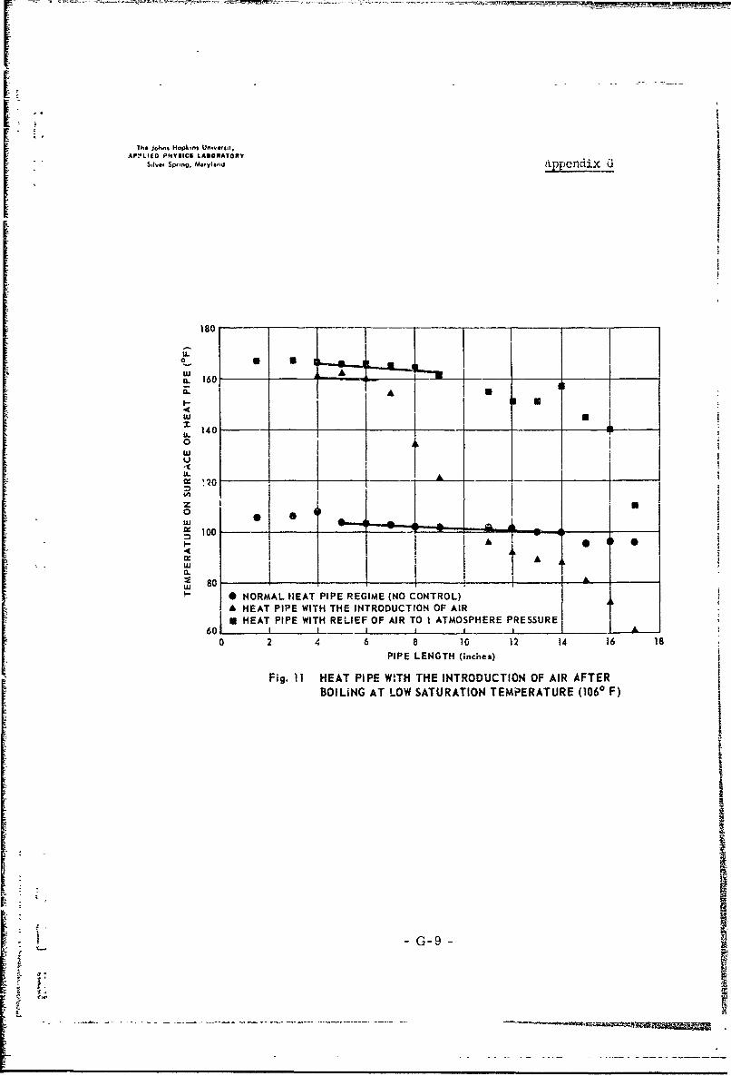
The majority of the above experiments were conducted at or near
173"F ST and partial evacuation was achieved by boiling. Figure .10 shows that
heat pipe regime obtained at lower ST where air was evacuated by a vacuum pump.
Figure 11 simply illustrates "travel" up the p-T curve.
G-4.

II--thi Johns Hopkins Unov, t ;#y
APPLIED PNYSICI LASORATORY
s..,- m,,,yi.n Appendix G
140iU
. "' U.
zw0 10.
rex I
w U..C.0 PIPE TILTED 30 AND 2 INCH GAP IN WICK LOCATED 2 INCHES FROM COLD ENDIE* HORIZONTAL PIPE WITII 2 INCH GAP IN WICK LOCATED 2 INCHES FROM COLD ENDLUJ
80 1 I I i I I I.I. .0 2 4 6 8 10 12 14 Is 18
PIPE LENGTH (inches)
Fig. 3 COMPARISON OF TEMPERATURE DISTRIBUTIONWITH EFFECT OF DISCONTINUOUS WICK, 1000 - 1400 F
190
Ir°u 170 ..
z u• II0 ILIUJ
,uJ u. 0 PIPE TILTED 30 AND 2 INCH GAP IN 10ICK LOCATED 2 INCHES
o,.
( 170
FROM COLD END (STEADY STATE)a HORIZONTAL PIPE WITH 2 INCH GAP IN WICK LOCATED 2 INCHE.- FROM COLD END
130- 1 - -- -
0 2 4 6 8 10 12 14 16PIPE LENGTH (inclms)
Fig. 4 COMPARISON OF TEMPERATURE DISTRIBUTIONWITH EFFECT OF DISCONTINUOUS WICK, 1500- 1900 F
GL
-- ~-~~ _ _ _ _ ---- --G -5__ _ __ _ __ __-_ _

U
The Johnm m-Ipk~n& Un-,wi~ta-
APPLI&D PNYHICS LASOIATORYs.,,.w s win,. M•f,,• . d, Appendix G -
1190
4U.
z 170
00IL
wu-
U- 150_ _-_._____L.
0 246 8 I0 12 14 16 18
PIPE LENGTH (inches)
Fig. 5 INTERRUPTION OF VAPOR FLOW (PLUG WITH 1/4-INCH-DIAMETER HOLE)
U.19 • -----
:z~ ~~ ~ w 170.o .c.,o,"
0" ,Il - . *T..0 NORMALHEATPIPEPREGIME (NOCONTROL)
U HEAT PIPE WITH 1/10-INCH-DIAMETER PLUG
~130 - l _ _ _ _ - _
0 2 4 6 8 10 12 14 16 18
PIPE LENGTH (inches)
Fig. 6 INTERRUPTION OF VAPOR FLOW (PLUG WITH 1/10.INCH.DIAMETER HOLE)
-G-6-

[IIThe JohnI HOp..,s U.ývwv:y
""s,, S,.,ng. Ma,, .nd Appendix G
210
0
w ACL
( 190I.
. U._. 0 170
i ::3 150 -=
z0
S " P 130 ,
| •0 NORMAL HEAT PIPE REGIME (NO CONTROL)rW 8 HEAT PIPE WITH 1/10INCH-DIAMETER PLUG (TRANSIENT)Q.
A HEAT PIPE WITH 0-INCH-DIAMETER PLUG (TRANSIENT)
S0 2 4 6 8 10 12 14 16 18• " PIPE LENGTH (inches)
Fig. 7 INTERRUPTION OF VAPOR FLOW (PLUG WITH NO HOLE)
"' 180S~u
S• ~z w 160 ---- O---0-
a. o 0 NORMAL HEAT PIPE REGIME (NO CONTROL)" HEAT PIPE FLOODED WITH ETHYL ALCOHOL• 1 20- i m
•-- •• 4610 8 12 14 1618
SPIPE LENGTH (inches)
. Fig. 8 HEAT PIPE WITH EFFECTS OF FLUID FLOODING
Gi
PIPE WIT EFET- FFUDFODN

- --- --. +' .--1, ---- -- . . .
I
Ihe John$ Hopkins Uneverlity
APPLIED PHYSICS LABORtATORY
S.•v.. ,.Ma~ylod Appendix G
w 180u
0 a
IlIA= 14,0IIIU: u.L 0 NORMAL HEAT PIPE REGIME (NO CONTROL) UEw 8 HEAT PIPE WITH INTRODUCTION OF AIR
120 I I I I0 2 4 6 8 10 12 t4 16 18 - -
PIPE LENGTH (inches)
Fig. 9 HEAT PIPE WITH INTRODUCTION OF AIR
w120U.* 0
too-11 ORA ETPIERGM WITH N COTO (SEAY TAE
"I- 6100 ....... .I I
0 21
- ~PIPE LENGTH (inches)"Lu CLFa. 10 HEA PORPE OPERATPION ATIM LWIT SATRATONTO TEMPERDSATUE(16F)
i
-G-8 -•
7h& Johns Hopkins Unsveit$a,AP0L1(O PNYSICS LANORATORY
S,,"t, Spring. Maryland appendix G
180 -
U A
a. 160
I- a
zU.140
uJu
o I I-o Aw
S100-
I I A
j 80 10 NORMAL hEAT PIPE REGIME (NO CONTROL)A HEAT PIPE WITH THE INTRODUCTION OF AIR• HEAT PIPE WITH RELIEF OF AIR TO I ATMOSPHERE PRESSURE __
60 I ____II L
0 2 4 6 8 10 12 14 16 18
PIPE LENGTH (inches)
Fig. 11 HEAT PIPE W.TH THE INTRODUCTION OF AIR AFTERBOILING AT LOW SATURATION TEMPERATURE (1060 F)
G-
-• -G-9
L..I

Tý jWM ""f •V Appendix G
Conmient'
Generally the control t'3n.hniques were satisfactory. The choking of
the pipe when the vapor regime was interrupted, with a plug having a 1/o0" D
hole, suggests that valves with small openings can cause pressure drops and
consequently short circuiting. The effect of condenser parameter variation
was most satisfactory. This technique comes closest to stopping the heat pipe.
Introduction of air as a non-condensable is an inferior technique owing to the
existence of water vapor which acts ab an impurity if sufficient quantity is
introduced.
Since the plugs were aluminum and the heat pipe was stainless steel,
an electroJytic reaction would result with sustained heat pipe operation.
It is felt that the evaporator and condenser walls must be of high
thermal conductivity whereas the middle section need not be. High thermal
conductivity of the witk is also very desirable.
1 was noticed that a loosely packed wick can cause alcohol vapor
bubbles to be trapped b-tween pipe wall and wicks. This causes a region of
high temperature to travel up Lo the evaporato:- and collapse. There is however
no particular signiffca.ce to this phenomena.
-G-1O-

If1 w )ohm -0bW tv Appendix G
References
1. Grover, G. M., T. P. Cotter, and G. F. Erickson, "Structures of very highther•r•l conductance," J. App!. Phy. 35, 1900 (1964).
2. Anand, D. K., "On heat -ripe performance," JSR, May 1966.
3. Wyatt, T., SDO-1389.
4. Swet, C. J., SDO-Ii67.
G-11 -
FI

SDOQ.1173
I - The jo~kn. Hep.n. Univte~ily An-Z rtL-" t .. . 4A£PPIEU PHWYSICS LASOIAIORY" -. Iwaw SWIF, Nwrlan
Subject: Partial Analysis of the Heat Pipe
Reference: (a) APL/JHU M,-mo SDO-1154 dtd 29 March 1965
In order to assist in the work on heat pipes and to allayany lingering doubts regarding the certainty of operation of theheat pipe at a predictable level in the orbital condition a simplifiedanalysis of one aspect is presented herein for consideration andcomment.
It appears probable that one of the major uncertaintiesin the practical design of a heat pipe and also the principal sourceof doubt concerning the operation of the heat pipe in the so-called"zero-g" environment of orbital motion is the nature of the capillaryflow in the device. Assume a capillary tube in static equilibrium"as depicted in Figure 1. The pressures acting on the liquid in thetube are the capillary pressure, 4,- cos 8, the gas pressures P1 and
"P2 0 and the gravitational head, hs a PV, using the following symbols:
T is the surface tension of the liquid
is the angle of contact at the edge of the meniscusbetween the liquid and the wall of the tube
D is the inside diameter of the tube
P 1 and P2 are the gas or atmospheric pressures at the points noted
h is the liquid head under static equilibrium
a -is the acceleration, gravitational or otherwise, againstwhich the tube is working
• t is the density of the liquid
-H-

the Johns Hop' ns Un,.*rs,IyAPPfLIED F14YSICSl bARGOIATORV
Ss., s,. ,y,, Appendix H
IDPI __ .
/
P2
P2 LIQUID LEVEL
"IN RESERVOIR
Fig. 1 CAPILLARY TUBE IN STATIC EQUILIBRIUM
H-2-

The Joh. Hkokn uO%;,.;1V Appendix HPP&.IIO IPNYSICS LAmO, AteaY
id,lr l..l, Sru i. M ly,•
With liquid-solid combinations wherein wetting occurs 0is less than 900, as illustrated, and if the wetting is particularlygood, as in the case of watei and glass, 8 0 0. Thus the staticpressure equilibrium of a selected case can be written
h (P- P2 ) (1)
The capillary tube is capable, under appropriate con-ditions, of delivering a sustained flow of liquid to some sort ofa removal process, such as evaporation at the meniscus as shown inFigure 2_. An "appropriate condition" in the context of the heatpipe is a value of hf less than hs. Assume that the sketch illus-
trates dynamic equilibrium, i.e., the flow rate and the evaporationraje are equal. Because of the low velocity of flow and the largelength-to-diameter ratio of the tube the viscous flow relationshipcommonly attributed to Poiseuille is applicable
I in128 LV (2)r D4 g
where
BP is the pressure drop in the liquid due to fluid flow
p ,.is the absolute viscosity of the liquid
L is the length of the tube
V is the volumetric flow rate
D is the inside diameter of the capillary tube, or the"*equivalent tube diameter" of a material which does notactually have discrete, measurable tubes. It is assumedthat the actual or equivalent tube diameter is the samefor both capillary and Poiseuille considerations.
g is the gravitational constant and is employed for con-sistency of units
andhf is the liquid head under a flow condition
The dynamic equilibrium can be written in terms of pressures as
4T" hi % a + (P1 - P-) +128 LV (3)
II1! D7 I- P2_+_ITg_(3H-

i Tlho John* Hopkmz Univtomly
APPLIEO PHYSICS LASOrATORY
S.I.t Swg. M.,,y.ad Appendix H
HEATINGELEMENT P1 VAPOR
SREMOVAL
WARMAIR
L hf
FLOW - I
P2
LIQUID1- REPLENISHMENT
Fig. 2 EVAPORATION AT THE MENISCUS
-H-4 '

The Johnis I"Sp~t'a Un-V.'..'v A p pC .-iiAPPLIED PN1VIC4 LA&GRATORY
S.IVW4 SWu~qg Maur4a"
It is apparent that the smaller the tube the greater isthe capillary pressure tending to produce flow; on the other hand,the larger the tube the greater is the flow rate for a given avail-able pressure.
In order to examine the counterplay of these contradictorytrends we shall hold all of the variables in the design constantexcept tube diameter, D. Then we can substitute in Equation (3)
k - hf p• a + (Pl- P1 2
and rearrange, getting
TT !~D[4 ] (4)V-128 L
Differentiating with respect to D and setting dV 0 we find thatthe maximum value of V occurs when
D (5)
Equation (5) is the basis for the designer to specifythe equivalent tube diameter which the capillary material shouldhave for his application and equation (1) provides means for him todetermine experimentally (by observation of the static head) theequivalent tube diameter of various materials in order to select onemeeting the requirement.
The other basic characteristic of the capillary materialis the number of equivalent tubes in a unit cross section of thematerial. One way of making this determination might be to observethe volume of flow during an interval of time through a relativelyshort length (so that V would be large) with accelerated evaporationinduced at the discharge end as shown in Figure 2 and then to calcu-late the number of multiples of '( (from Equation 4) present. In thecase of a very uniform material, such as porous ceramic or poroussintered metal (but not wire mesh or woven materials) whereinthere are no voids or passages larger than the equivalent tubediameter a simpler procedure might be to apply a pressure differentialacross a sample and, using Equation 2, determine the number of mul-tiples of '.
Applying the foregoing reasoning to a heat tube operatingat an input temperature of 20" C and using water as the working fluidwe employ the following physical constants and assumptions:
-H-5-
_ __

APPOIA PPSCS uOIAT-a, Annendix H
- 72.75 dynes/cm
g - 981 cm/sec2
a - g and 0
p - 1.0 gm/cm3
S- 0 .01002 poise (gm/sec cm)
Since the heat input end is at 200 C, P1 " 17.535 mm Hg or 23,4002dynes/cm
We shall assume a temperature drop across the heat tube of 0.20 C,which is probably excessively large, but show later that this as-sumption is not critical in the gravitational case.
Then
P2 = 17.319 mm Hg or 23,100 dynes/cm2
For the application suggested in Reference (a) the geometry is ap-proximately as illustrated in Figure 3, which is a marked-up versionof an earlier sketch employed in Reference (a). Although we areprobably justified in designing for a desired flow rate to the mid-point of the battery tube we shall employ both that tube length andhead and also the length and head to the top of the battery tube, thelatter for conservatism, Then
Case I and Case II
hf 1.5.9 cm hf M 24.8 cm
L - 17.8 cm L - 26.6 cm
Since we are interested in both the performance of thecapillary under an environment of 1 g, e.g., in a laboratory thermal-vacuum test chamber, and also under an environment of zero-g in orbitwe shall first solve equation (5) for each set of conditions, andthen equation (1) and (4). The results are tabulated below.
•1 g environment* '0 g environment
D V hs D h s**cm cc/sec cm cm cc/sec cm
3Case I .0137 2.52 X 10⁻² 21.6 .7275 3.78 X 10 .47,
-33Case HI .0088 4.5 X 10- 33.7 .7275 2.53 X 10³ .41* i.e., working against 1 g• not applicable in 0 g, but the value quoted is for the optimum value
of D for 0 g as observed under 1 g.
H-6i

Thrr John$ Hopk.n; Unniv.t,tvAPPLIED PHYSICS LABORATORY
S,,n., rSog. Maryland Appendix 1-
lit
I I I
STORAGE -CELLS -a- BATTERY TUBE
ELECTRICALINSULATION
LI 11iiiI
I~ I,I ~ I'
-fl
HEAT TUBE,HEAT FLOWIN EITHER SPLIT FLANGE CLAMPINGDIRECTION PANCAKE END OF HEAT TUBE
TO BASE PLATE
BASE PLATE
NOTE: WORKING FLUID AND CAPILLARY WICKINGWITHIN HEAT TUBE NOT SHOWN
Fig. 3 SUGGESTED METHOD OF THERMALLY CONNECTINGBATTERY TUBE TO BASE PLATE
H-7
: [__ - H --7_-

1 19
r I . •._ ,. , Appendix HAPPLto P IYS•i LASO ATORY
The radical effect of the presence or absence of a gravi-tational or other force field is apparent. In performing thesecalculations it is noted that k is composed of hf 4 a .2 X 10 and
(Pl- p2 ) - 3 X 10². Thus the effect of a modesttemperature or pres-,
sure drop along the tube on the choice of D and on the value of Vrealized is slight in the gravitational case but must be allowed forconservatively in the orbital case.
One might design a heat pipe to operate optimally against1 g so as to permit operation of all other portions of the satelliteat the design point in ground testing. The Case I design employingthe 1 g choice of D would, in the 0 g environment, be capable of
V = 9.9 X l0o. Similarly, Case II would be capable cf V 01.78 X 02in orbit. This course of action would have the advantage of groundcheckout in the most adverse attitude, but with a substantial over-design for orbital use. The only apparent justification would besome stringent limitation of a ground test set-up.
A more desirable procedure in the case of an orbital ap-plication employing a straight pipe would be to design for 0 g andto check the operation of the heat pipe in a horizontal position soas to get effectively 0 g in the principal dimension.
-H-8-I
I-'

itINITIAL DIST•,IBUTION EXTERNAL TO THE APPLIED PHYSICS LABORATORY*
The work reported in TG-922 was done under Navy Contract NOw 62-0604-c. The work was relatedto Task Assignment 171 ,hich is supported by National Aeronaut•sc and Space Administration.
ORGANIZATION LOCATION ATTENTION Cap.es
DEPAir'fMENT OF DEFENSE
I) DC Alexandria, Va. 20
iDepartmnent of the Navy
NAVORDSYSCOM Washington, I). C. ORD-9132 2NAVI'LAN.'RE!1O Silver Spring, Md.
L.S. GOVERNMENT AGENCIES
Nationai Aero. and Space Adinin.
Offices
I h•,aqdarters Washington, D. C. AD IOffice of Space Sc;ences and
Applications Washington, 1). C. S 1SD ISA 1SAG 1SG 1
Office of Advanced Research adTechnolog) Washington, I). C. R I
RN IRND I3•NW I
('enters
Goddard Space Fl1. Ctr. Greenbelt, Md. 100 1700 1713 1720 1
Langley Research Cir. Hampton, %a. Technical Library 1Aniesi Research Ctr. Moffett field, Calif. Library I
[ ~~Requwtst fw €opie, of thos report f.), D*D wctivitio ý'. contractos shmoq 4 44t ,octed to 01>C,Cameron Station, AtexqJthis, Virtiml2 22319 using ODD For, I o". it nocosiory,, VDC Form 55.iL
'Initial dstributon of this docun-ent •withinthe Appli*e Physics Loborotory has be"n made in accortnce with a list ot I66s in the APt- Technical Reports Group.
ii
°1

t ~Se-cs-ricv C-lass~fication- --- )CUMENTE CO)NTROL DATA -. R&D
(Security :10aril~vace. , 4 file&, bao'1' ci abst-oct und ,i~foxiig rnnaototiar, must be ontared w'hen the ov*tuil repairt is lasdsd)
I. ORIGINATING ACT ViTY (Ca-portot author) 2o. REPORT SECURITY CLASSIFICATION
The .iohns Hopkins Univ. , Applied Physics Lab.8621 Gxeorgia Avenue 12k. GROUP
L ~~. ~ ~ _Maryland __ ________
Heat Pipe Application fo pa,-craft Thermal Control
4. DESCRIPTIVE 140 CES (Typ. ofrrpor enS nctusr.. dates)
Technical Moemorýý:cluai___S. AUTHOR(S) (Lost name, first name, itiall
r). K. Anand a,.( R~. B. Hester
6. REPORT DATE 7o TOTAL NO. OF PAGES ~7b. NO. OF R EFSA- uus t 19 67 ___ ___J94 '2 7
so. CNTRA-,T OR GRANT NO. g o. ORICINATOR'S REPORT NUMBER(S)
V NOw 62-0604-c TG-S22b. PROJECT '4O.
Task Ass-ignment J71C. .4b. OTHER REPORT NOW(S Any ether nuhr.,es that may be assigned
this report,
110. AVAILABILITY/ LIMITATION NOTICES
Thizr document has beers appro-ved for public release and sale; its distributionis unli-mited.
11. SUPPLEMENTARY NOTES 112. SPONSORING MILITARY LV1.
National Aeronautics andI Space Administration
13. ABSTRACT
A heat pipe is a device which exhibits an extremely high effectivethermal conductivity by means of two-phase fluid flow with capillary circu'lation.
,phe primary objective of the experimental program was -.o determine
a suitable method of control for the heat, pipe and to establish suitable wick/fluidconfigurations for the various temperature ranges of interest.
The Primary r~liective of the prototype program was to provide design,construction, testing for verification, and flight hardware specifications of aheat pipe applicable to therm.- control of a spacecraft or a spacecraft subsystem.Thus, a thermal design improvement for spacecraft could b4: proposed; in addi-tion, thermal resistances of heat pipes could be derived.
DDF ̂ O 41473 - UNCLASSI FIEDL Security Classification

I i('a t PipeWick/ FIL!Id C0YlfigfUr'tions-
Thornma Desig-
UNCLASSIFIED
Security Classification