heat exchangers - shritarashritara.in/pdf/heat_exchangers_rev.pdfshell & tube tema type heat...
TRANSCRIPT
Phone: 022-288-13803 Fax: 022-2881-3803 E-mail: [email protected] Cell: +91 9820191532
61/62, Unique Tower 4, Padma Nagar, Near Evershine Ngr, Off Link Road, Malad (west), Mumbai -64, India
SEPC
SEPC Quality Supplies Guaranteed
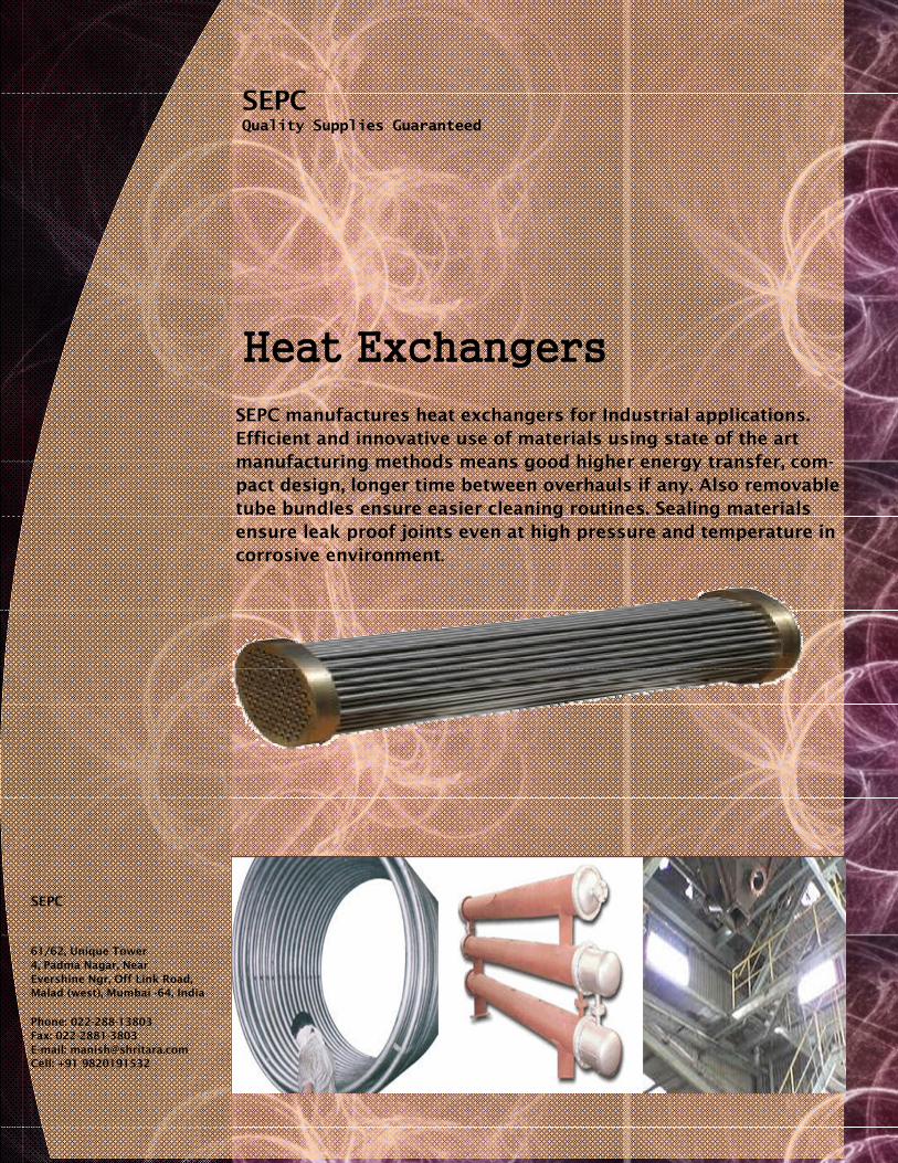
SEPC manufactures heat exchangers for Industrial applications. Efficient and innovative use of materials using state of the art manufacturing methods means good higher energy transfer, com-pact design, longer time between overhauls if any. Also removable tube bundles ensure easier cleaning routines. Sealing materials ensure leak proof joints even at high pressure and temperature in corrosive environment.
Heat Exchangers

Model
Dimensions Dissipated Oil Flow Water Oil Water Power Rate Flow Pressure Pressure Surace
Drop Drop
Weight
A B C D E F kW l/min. l/min. bar bar m2 kg HX-A 1 195 72 38 86 ¾” 3 30 15 0.10 0.02 0.13 3
HX-A 2 263 142 106 86 ¾” 6 46 23 0.19 0.05 0.22 3.5
HX-A 3 349 228 192 86 ¾” 9 56 28 0.36 0.09 0.32 4
HX-A 4 448 326 290 86 ¾” 13 64 32 0.60 0.13 0.46 4.7
HX-A 5 576 454 418 86 ¾” 16 56 28 0.56 0.12 0.68 5.5
HX-B 1 273 123 109 108 1”
8 66 33 0.16 0.02 0.33 5
HX-B 2 355 205 190 108 1”
12 80 40 0.32 0.03 0.48 6
HX-B 3 452 302 289 108 1”
18 104 52 0.96 0.07 0.66 7
HX-B 4 587 437 422 108 1”
25 106 53 1 0.11 0.90 8.2
HX-B 5 730 580 566 108 1”
29 98 49 1.04 0.14 1.16 10
HX-C 1 372 187 93 130 1¼” 16 100 50 0.28 0.04 0.64 9
HX-C 2 472 287 193 130 1¼” 26 120 60 0.55 0.07 0.90 10
HX-C 3 600 416 322 130 1¼” 36 140 70 0.74 0.13 1.23 12.5
HX-C 4 744 559 465 130 1¼” 48 160 80 1.06 0.17 1.60 14.5 HX-C 5 922 737 643 130 1¼” 56 140 70 0.95 0.16 2.07 17.5
HX-D 1 505 273 109 162 1½” 40 180 90 0.40 0.07 1.58 20
HX-D 2 634 402 238 162 1½” 52 200 100 0.55 0.09 2.14 24
HX-D 3 780 548 384 162 1½” 66 220 110 0.62 0.12 2.79 27
HX-D 4 954 722 558 162 1½” 84 240 120 0.80 0.16 3.57 32
HX-D 5 1160 928 764 162 1½” 108 260 130 1 0.19 4.48 38
HX-D 6 1364 1132 968 162 1½” 120 240 120 0.96 0.21 5.38 45
HX-E 1 675 372 239 198 2”
76 320 160 0.44 0.09 3.27 33
HX-E 2 816 513 380 198 2”
106 360 180 0.64 0.13 4.24 39
HX-E 3 998 696 560 198 2”
134 400 200 0.90 0.20 5.45 45
HX-E 4 1204 901 766 198 2”
175 420 210 1.10 0.25 6.82 54
HX-E 5 1408 1102 968 198 2”
205 400 200 1.15 0.28 8.22 64
HX-E 6 1712 1406 1272 198 2”
240 360 180 1.10 0.28 10.27 75
HX-F 1 754 330 236 278 3”
133 720 360 0.36 0.09 7.20 47
HX-F 2 900 476 382 278 3”
180 780 390 0.50 0.13 9.14 57
HX-F 3 1077 654 560 278 3”
250 840 420 0.62 0.17 11.81 68
HX-F 4 1280 856 762 278 3”
325 900 450 0.76 0.25 14.60 79
HX-F 5 1484 1060 966 278 3”
410 960 480 1 0.32 17.30 91
HX-F 6 1790 1364 1270 278 3”
500 900 450 1.16 0.52 21.54 105
Dimensions
A
Benefits of using Standard Make Branded HX
Standardised Design for bulk applications like , Oil Cooler, Condensor, Pre-Heater for lubrica-tion fluids, thermic fluids, coolants in machine, marine engines, heavy duty automobiles, chemical plants skid mo nted nits for pros
Standard Design Heating / Cool-ing Multiple quantity 100% interchangeable parts
Robust design CNC Machining Original Seals Polished Tubes—minimum foul-ing Easy Fitting

Shell & Tube TEMA type Heat Exchangers: U Tube, Floating Head, Stacked type Fixed tubesheet with Expansion Bellows, Reboiler with Tube bundle, Coil in Tank-Type, Heater bank in vari-ous configurations, Double pipe (Pipe In Pipe), Single / Multiple pass exchangers are the various designs supplied. Common design as per TEMA ‘R’ & ‘C’ : AES, BEM, AEP, CFU, AKT, and AJW.
Designed and Tested: Every exchanger is designed as per TEMA ‘R’ - Severe Service like Pe-troleum, ‘C’ - Commercial applications like low pressure heat dissipa-tion or ‘B’ - Chemical Plant Service.
Each & Every pressure or load bearing part is traceable to origin(Mill TC). For other parts, weldable steel or suitable chemistry if ensured. Use of Current Drawing with Quality Plans, ITP’s, MTC, Welding Proce-dures, Calibrated Instruments, Safe working Procedures, ensure good workmanship and fixed time schedule. Customized or Bespoke exchangers are also fabricated as per HTRI guidelines. Capacity to manufacture Up to 6 meters long x 1.25 m diameter, up to 2” OD tube size, Stainless Steel, Carbon Steel, LAS, Brass, Copper, Alu-minum, Incolloy,etc. Fixed, Floating Head, U Tube, Double pipe, Re-boiler, Condensor, Economiser, Pre-Heater,

Theory and Application of Shell & Tube Water Oil Coolers Two fluids, of different starting temperatures, flow through the water oil cooler. One fluid flows through the internal tubes and the other flows around the tubes inside the shell. Heat is transferred from one fluid to the other through the tube walls, either from inside the tubes to the surrounding fluid or vice versa. Design Features Shell & Tube Water Oil Coolers are designed to provide for most power classification or ranges in the oil- hydraulics applications. The coolers range from the smallest size (SE-CM) with 2 KW of heat trans-fer power to the largest size (SE-CX) with 500 KW per average. Shell & Tube Water Oil Coolers are designed as floating head tube bundles. Materials of construction Industrial Cooler: Shell: Aluminium, Bronze | End Covers: Hot Pressed Brass, Bronze | Tubes: Copper, CuNi 90/10 1 Baffles: Aluminium | End Plates: Brass | 0-Rings/Seals: Nitrile / Neoprene / EPDM. Marine Cooler: Shell: Aluminium, Bronze | End Covers: Hot Pressed Brass, Bronze J Tubes: Copper, CuNi 90/10 | Baf-fles: Aluminium | End Plates: Brass | O-Rings/Seals: Nitrile / Neo-prene/ EPDM. Limitations Maximum Design Temperature: 94°C with NBR seals (Operating Temperature is around 600C). Design Pressure: Oil side 15 bar / Cool-ant side 10 bar (pressure - temperature charts Kindly refer to manual).
Installation and Maintenance Shell & Tube Fluid Oil Coolers may be installed either in vertical or horizon-tal position but both fluids rnust cir-culate as a ‘counter current flow’. The cooler could be installed either in the return line to the tank or in a closed circuit, and bypass isolating shall be set in place to allow for maintenance.
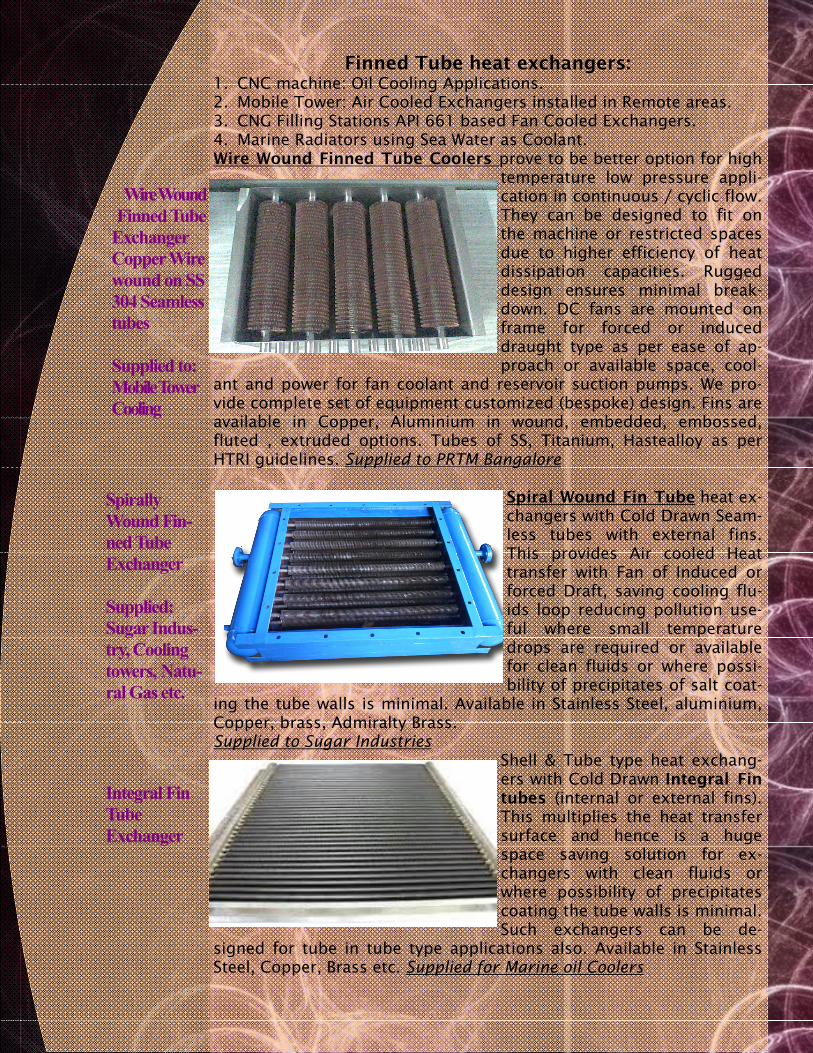
Finned Tube heat exchangers: 1. CNC machine: Oil Cooling Applications. 2. Mobile Tower: Air Cooled Exchangers installed in Remote areas. 3. CNG Filling Stations API 661 based Fan Cooled Exchangers. 4. Marine Radiators using Sea Water as Coolant. Wire Wound Finned Tube Coolers prove to be better option for high
temperature low pressure appli-cation in continuous / cyclic flow. They can be designed to fit on the machine or restricted spaces due to higher efficiency of heat dissipation capacities. Rugged design ensures minimal break-down. DC fans are mounted on frame for forced or induced draught type as per ease of ap-proach or available space, cool-
ant and power for fan coolant and reservoir suction pumps. We pro-vide complete set of equipment customized (bespoke) design. Fins are available in Copper, Aluminium in wound, embedded, embossed, fluted , extruded options. Tubes of SS, Titanium, Hastealloy as per HTRI guidelines. Supplied to PRTM Bangalore
Spiral Wound Fin Tube heat ex-changers with Cold Drawn Seam-less tubes with external fins. This provides Air cooled Heat transfer with Fan of Induced or forced Draft, saving cooling flu-ids loop reducing pollution use-ful where small temperature drops are required or available for clean fluids or where possi-bility of precipitates of salt coat-
ing the tube walls is minimal. Available in Stainless Steel, aluminium, Copper, brass, Admiralty Brass. Supplied to Sugar Industries
Shell & Tube type heat exchang-ers with Cold Drawn Integral Fin tubes (internal or external fins). This multiplies the heat transfer surface and hence is a huge space saving solution for ex-changers with clean fluids or where possibility of precipitates coating the tube walls is minimal. Such exchangers can be de-
signed for tube in tube type applications also. Available in Stainless Steel, Copper, Brass etc. Supplied for Marine oil Coolers
Spirally Wound Fin-ned Tube Exchanger Supplied: Sugar Indus-try, Cooling towers, Natu-ral Gas etc.
Wire Wound Finned Tube
Exchanger Copper Wire wound on SS 304 Seamless tubes Supplied to: Mobile Tower Cooling
Integral Fin Tube Exchanger

Heating & Cooling coils for Large Tanks & Reaction Vessels Heat exchange can also be effectively implemented through Use of metallic coils
mounted inside large concrete tanks open to atmosphere. Heater reduces the high vis-cosity and prevents so-lidification or coagula-tion e.g. tar, bitumen, resin etc.,
Agitated reaction vessels use internal coils to heat or cool using steam or cold water for various process requirements,
Coils inside closed fixed roof and floating roof & fuel tanks are used in cold weather location for keeping hydrocarbon in liquid phase and sometimes cooling coils are required to keep VOC losses low in highly volatile fluid tankages ,
Heating of edible substances for cooking, boiling and drying. Use of steam is a non invasive and efficient solution rather that use of furnace oil, wood or gas as an external burner. Steam can be raised to high temperature (superheated) to ef-fective flash dry some solids giving excellent properties of dry powders.
Use of Coils is wide-spread as Sampling points to reduce tem-perature of process fluids intended for Laboratory Samples at intermediate loca-tions in Plants.
Multiple coils for even heating

Dimple Jacketed Process Equipment Dimple Jacket Heat Exchangers & Agitated Vessels Greater efficiency of heat transfer heat flows rapidly from the outer jacket wall through the weld contact area of Dimpled Jacket with Tank wall. Overall heat transfer coefficient “U” is significantly higher. When a conventional jacket vessel is de-signed, the required shell thicknesses are the function of the di-ameter, design pressures, and the unsupported length of the inner shell. Any increase of these values necessarily leads to an in-crease in material thickness. The dimpled jacket makes a thinner wall possible, because it is based on using a relatively short dis-
tance between the dimples. Through the use of the large number of reinforcing dimples, the thickness of both the inner and outer walls can be consid-erably reduced. Reduced Cost & Weight Improved Heat Transfer Ability Ideal for Clean Fluids where Agitated Vessels require process
side anti scaling properties. Design Pressure : 100 psig Design Temperature : 200 0 C MOC : Stainless Steel 304, 316 Al, Carbon Steel. Wall Thickness: 1.2 mm to 3 mm stainless Steel Dimple Size: 12.0 mm diameter x 50 mm rotated square. Can be supplied with Rolled shell, Conical and dished end or flat pillow type internal heating panels Applications:
Food Industry—Ice Cream Blending, Cream ripening. Tobacco Dryer & Grain Dryer Chemical Industry—Sulfur Re-melter tanks, Water cooled chute for Chemical product. Accessories Provided: Sight Glass, Square or Oblong Man-hole, Tubular Legs and Supports