heat exchanger design - msubbu.in
TRANSCRIPT

Heat Exchanger Design
Dr. M. Subramanian
Associate Professor
Department of Chemical Engineering
Sri Sivasubramaniya Nadar College of Engineering
Kalavakkam – 603 110, Kanchipuram (Dist)
Tamil Nadu, India
msubbu.in[AT]gmail.com
14-July-2011
CH2407 Process Equipment Design II
www.msubbu.in
www.msubbu.in
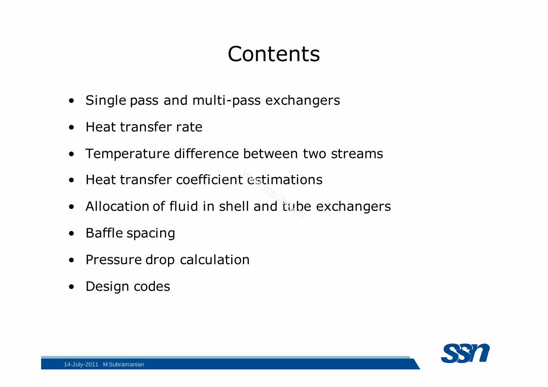
Contents
• Single pass and multi-pass exchangers
• Heat transfer rate
• Temperature difference between two streams
• Heat transfer coefficient estimations
• Allocation of fluid in shell and tube exchangers
• Baffle spacing
• Pressure drop calculation
• Design codes
14-July-2011 M Subramanian
www.msubbu.in
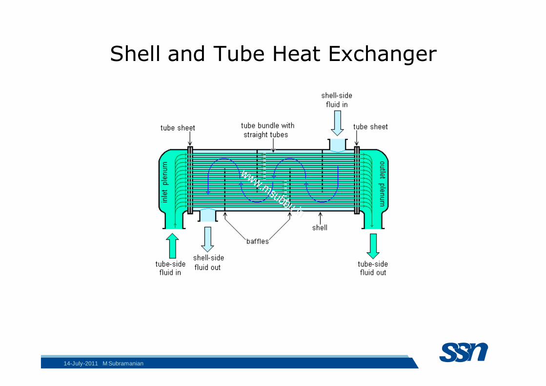
Shell and Tube Heat Exchanger
14-July-2011 M Subramanian
www.msubbu.in
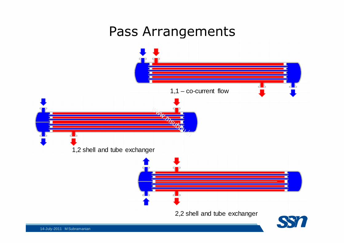
Pass Arrangements
1,1 – co-current flow
1,2 shell and tube exchanger
2,2 shell and tube exchanger
14-July-2011 M Subramanian
www.msubbu.in

Heat Transfer Rate
1
From first law of thermodynamics,
14-July-2011 M Subramanian
www.msubbu.in
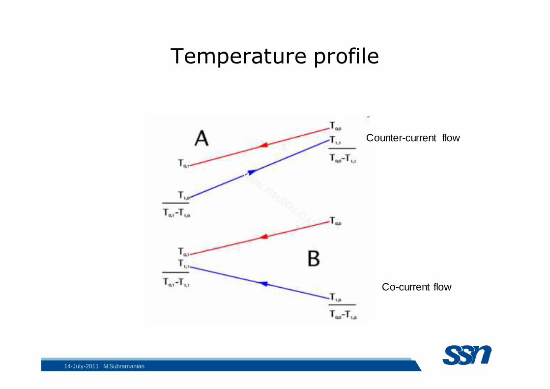
Temperature profile
Counter-current flow
Co-current flow
14-July-2011 M Subramanian
www.msubbu.in
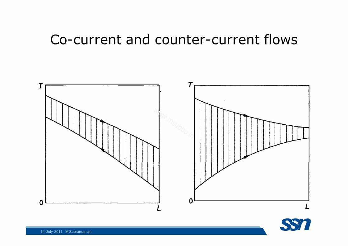
Co-current and counter-current flows
14-July-2011 M Subramanian
www.msubbu.in
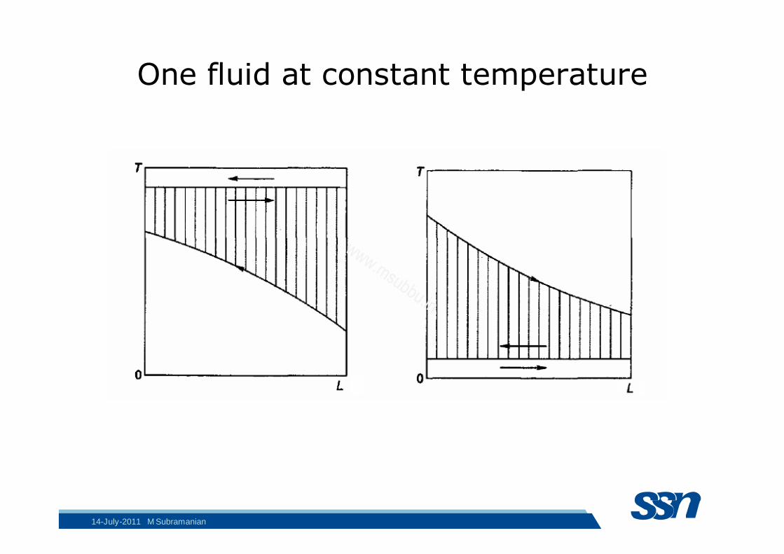
One fluid at constant temperature
14-July-2011 M Subramanian
www.msubbu.in

Temperature profile of condenser with de-superheating
14-July-2011 M Subramanian
www.msubbu.in

Temperature Difference
14-July-2011 M Subramanian
www.msubbu.in
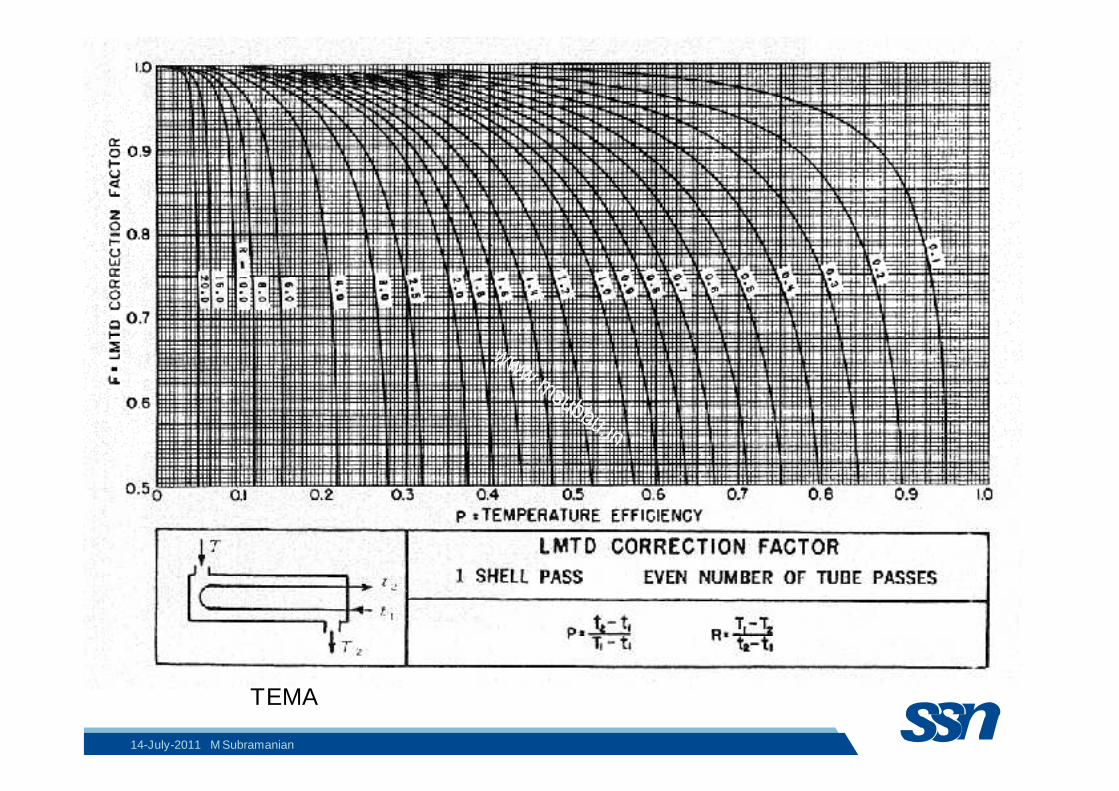
TEMA
14-July-2011 M Subramanian
www.msubbu.in
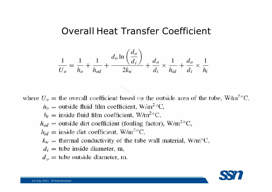
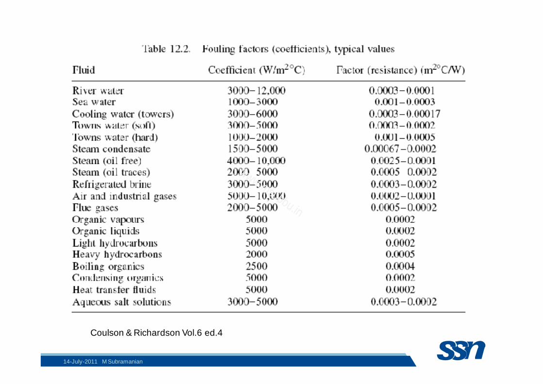
Overall Heat Transfer Coefficient
14-July-2011 M Subramanian
www.msubbu.in
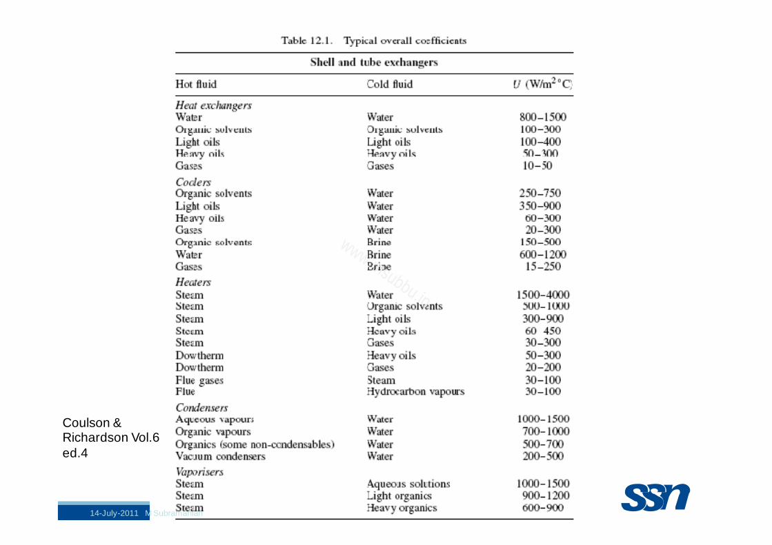
Coulson & Richardson Vol.6 ed.4
14-July-2011 M Subramanian
www.msubbu.in
Coulson & Richardson Vol.6 ed.4
14-July-2011 M Subramanian
www.msubbu.in
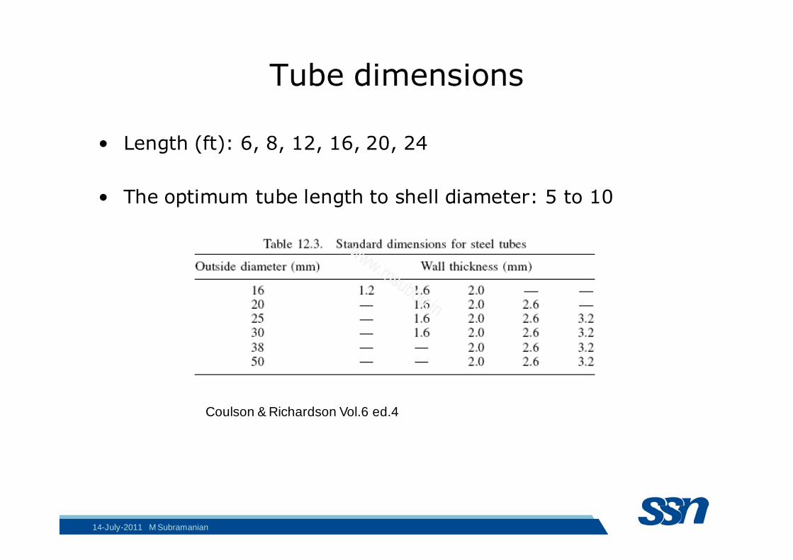
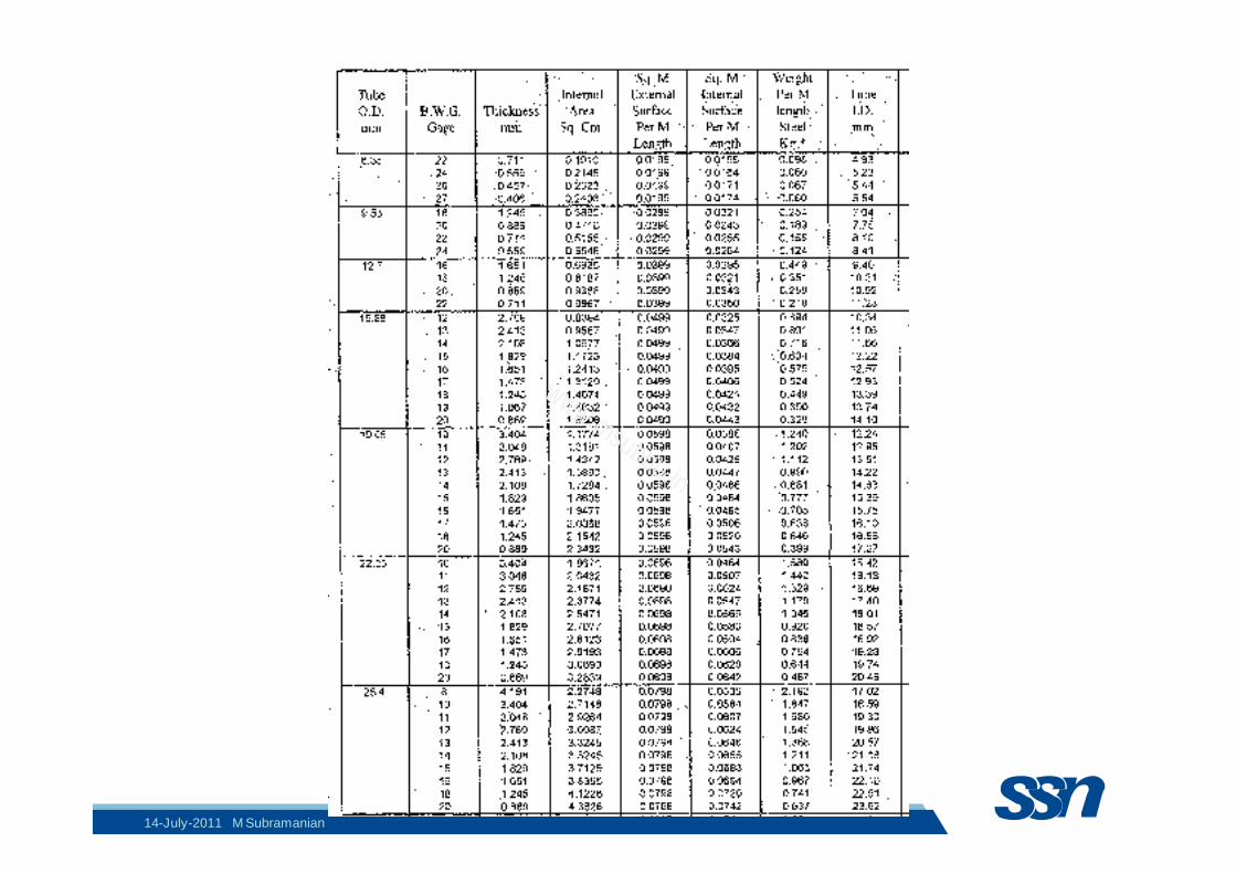
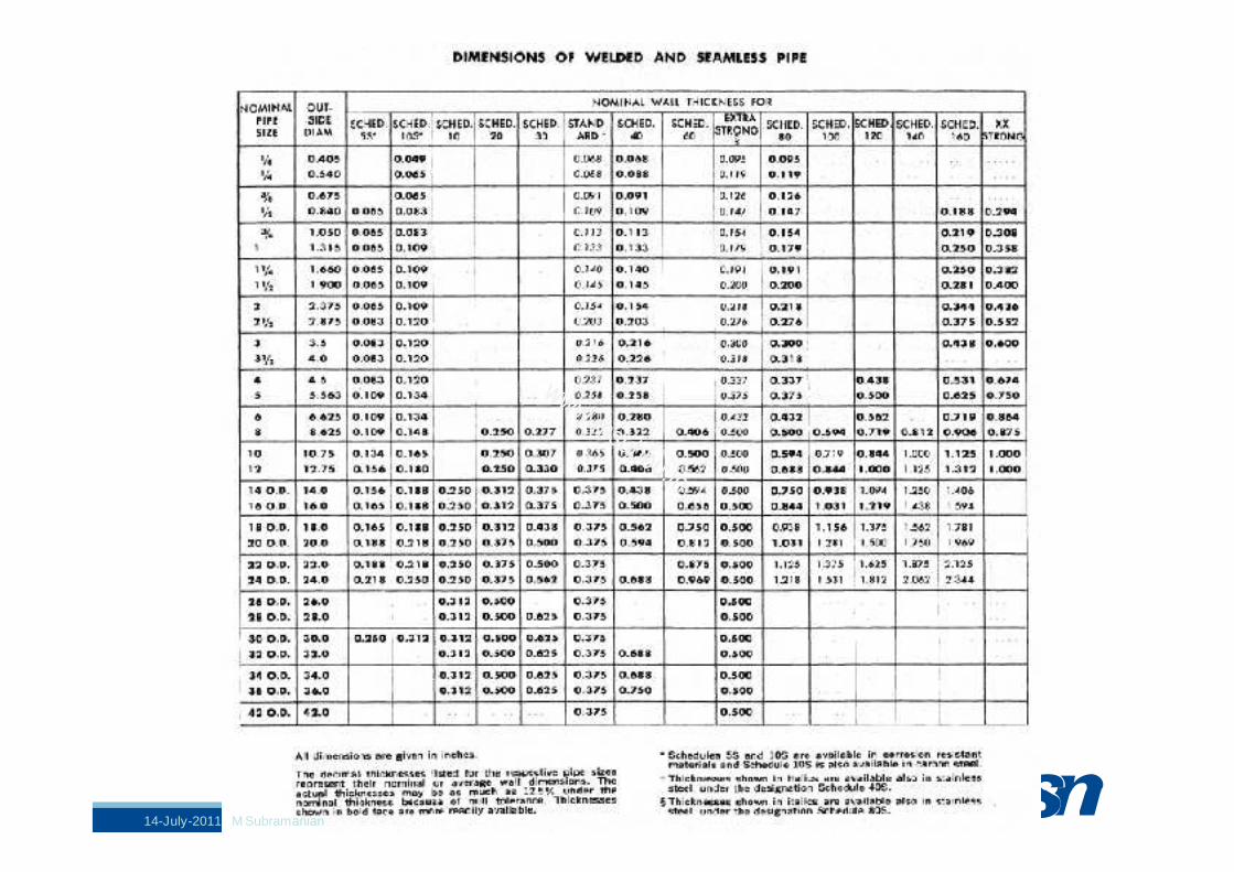
Tube dimensions
• Length (ft): 6, 8, 12, 16, 20, 24
• The optimum tube length to shell diameter: 5 to 10
Coulson & Richardson Vol.6 ed.4
14-July-2011 M Subramanian
www.msubbu.in
14-July-2011 M Subramanian
www.msubbu.in
14-July-2011 M Subramanian
www.msubbu.in
14-July-2011 M Subramanian
www.msubbu.in
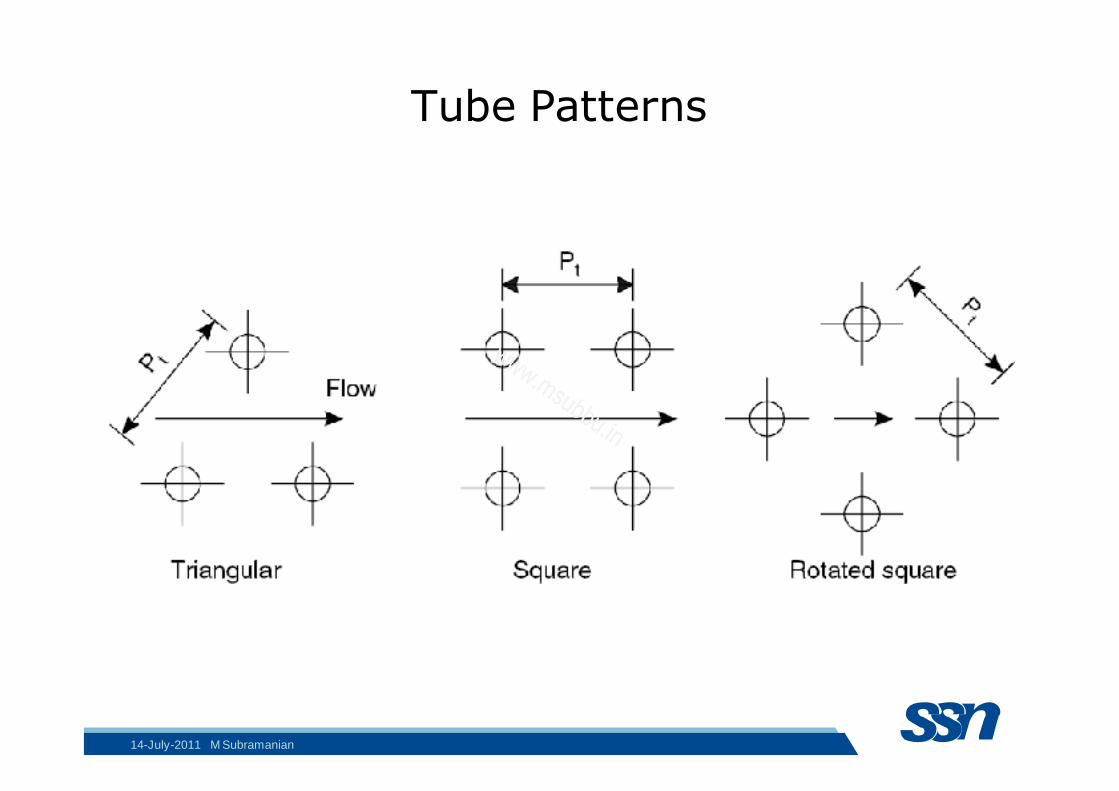
Tube Patterns
14-July-2011 M Subramanian
www.msubbu.in
Tube side passes
• Practical construction limits the number of tube-side passes to 8—10, although a larger number of passes may be used on special designs
• Even number of passes are preferred
• The higher the number of passes, the more expensive the unit
14-July-2011 M Subramanian
www.msubbu.in
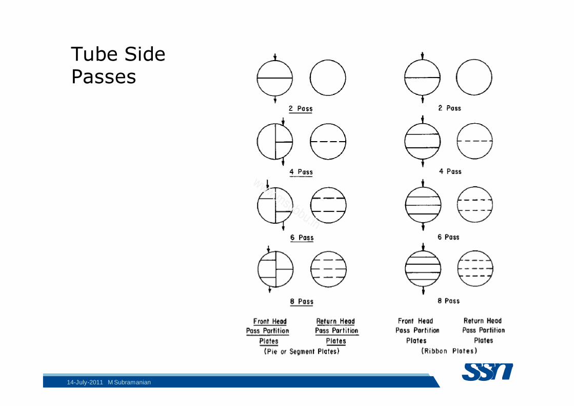
Tube Side Passes
14-July-2011 M Subramanian
www.msubbu.in
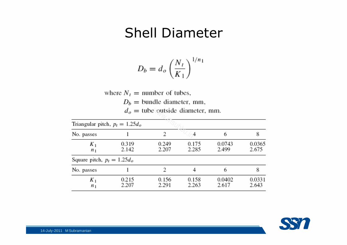
Shell Diameter
14-July-2011 M Subramanian
www.msubbu.in
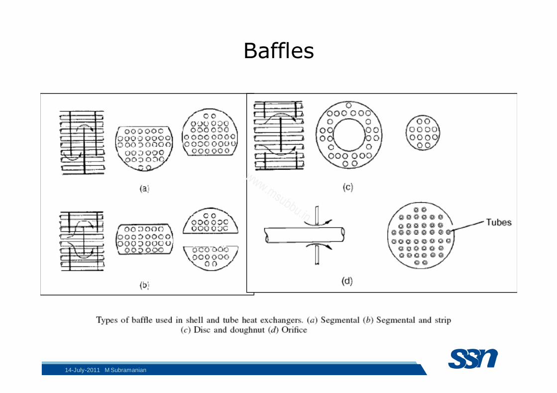
Baffles
14-July-2011 M Subramanian
www.msubbu.in
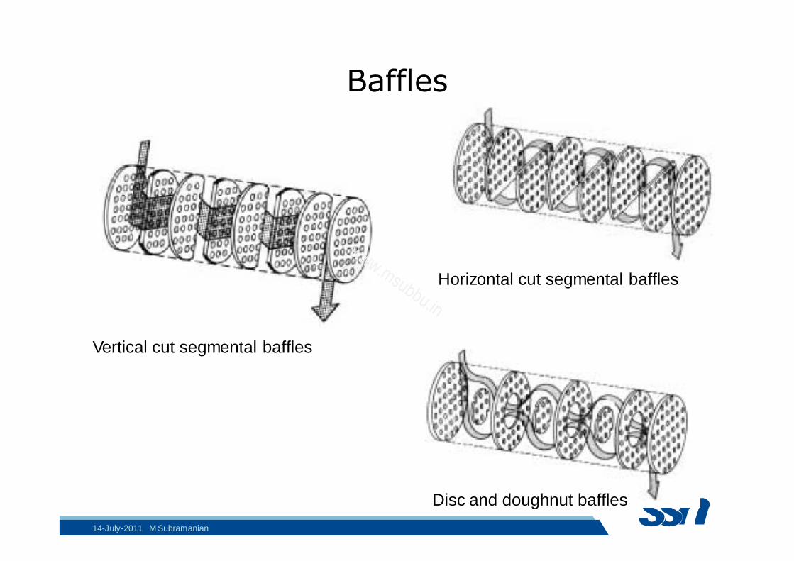
Baffles
Horizontal cut segmental baffles
Vertical cut segmental baffles
Disc and doughnut baffles
14-July-2011 M Subramanian
www.msubbu.in
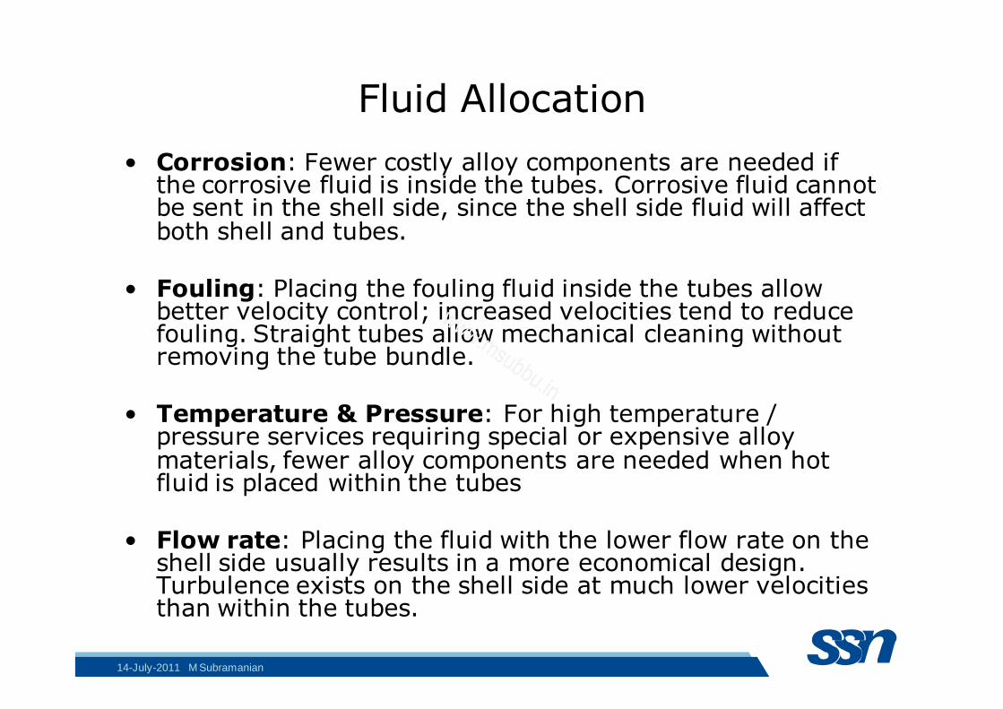
Fluid Allocation
• Corrosion: Fewer costly alloy components are needed if the corrosive fluid is inside the tubes. Corrosive fluid cannot be sent in the shell side, since the shell side fluid will affect both shell and tubes.
• Fouling: Placing the fouling fluid inside the tubes allow better velocity control; increased velocities tend to reduce fouling. Straight tubes allow mechanical cleaning without removing the tube bundle.
• Temperature & Pressure: For high temperature / pressure services requiring special or expensive alloy materials, fewer alloy components are needed when hot fluid is placed within the tubes
• Flow rate: Placing the fluid with the lower flow rate on the shell side usually results in a more economical design. Turbulence exists on the shell side at much lower velocities than within the tubes.
14-July-2011 M Subramanian
www.msubbu.in
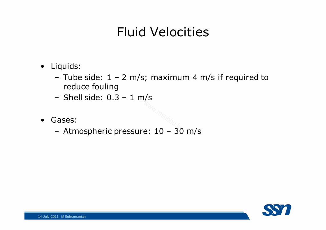
Fluid Velocities
• Liquids:
– Tube side: 1 – 2 m/s; maximum 4 m/s if required to reduce fouling
– Shell side: 0.3 – 1 m/s
• Gases:
– Atmospheric pressure: 10 – 30 m/s
14-July-2011 M Subramanian
www.msubbu.in
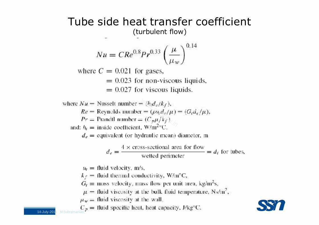
Tube side heat transfer coefficient (turbulent flow)
14-July-2011 M Subramanian
www.msubbu.in
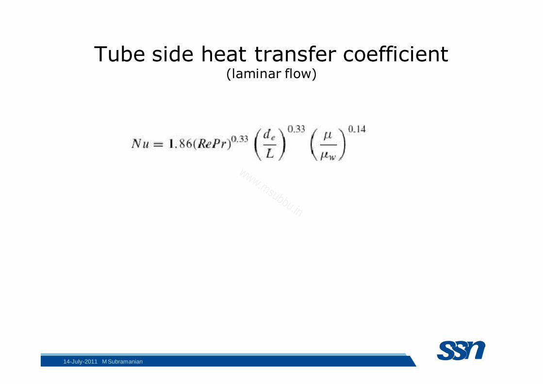
Tube side heat transfer coefficient (laminar flow)
14-July-2011 M Subramanian
www.msubbu.in
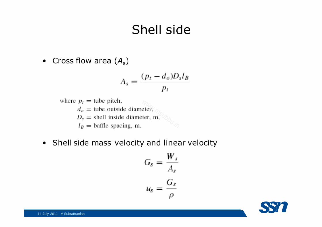
Shell side
• Cross flow area (As)
• Shell side mass velocity and linear velocity
14-July-2011 M Subramanian
www.msubbu.in
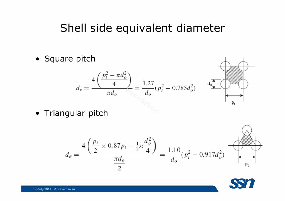
Shell side equivalent diameter
• Square pitch
• Triangular pitch
14-July-2011 M Subramanian
www.msubbu.in
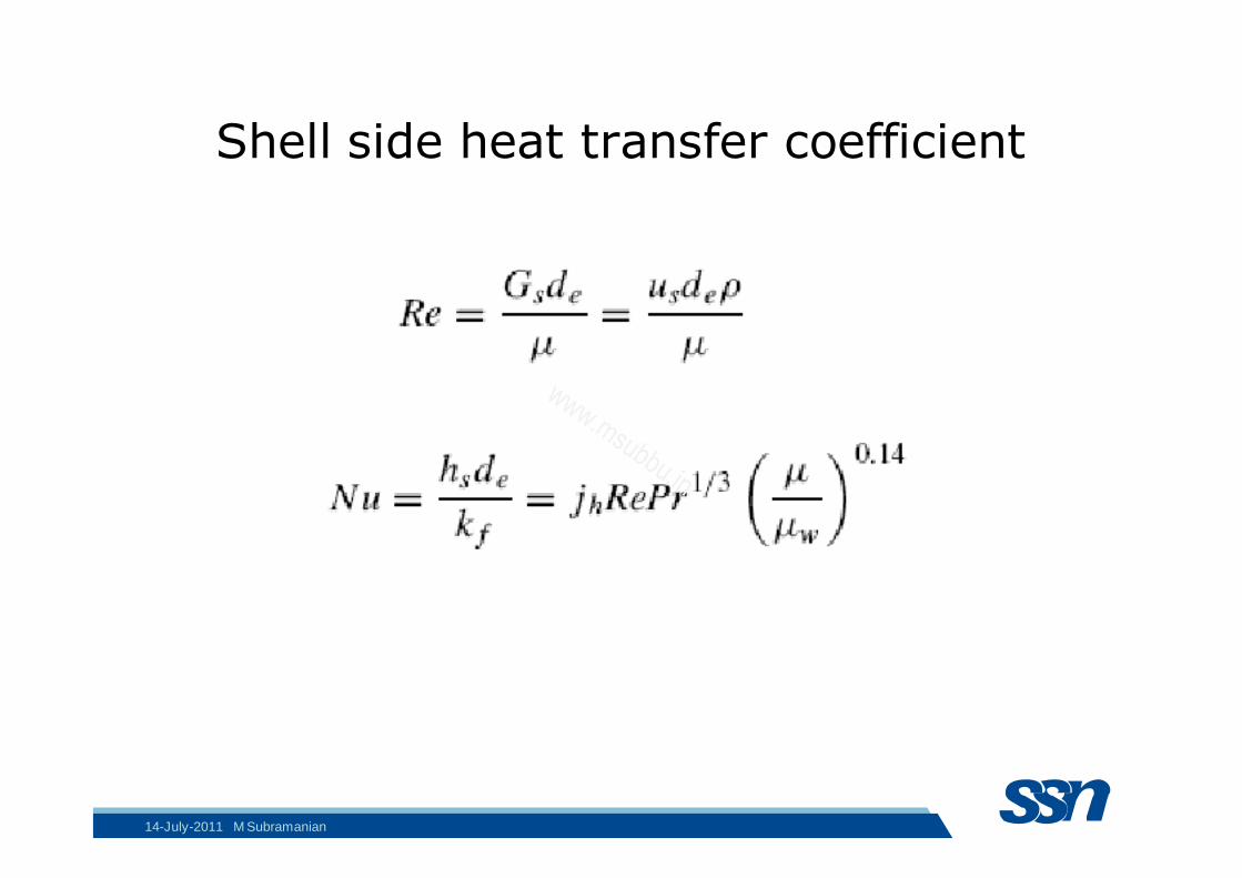
Shell side heat transfer coefficient
14-July-2011 M Subramanian
www.msubbu.in

Coulson & Richardon Vol.6 ed.4
14-July-2011 M Subramanian
www.msubbu.in
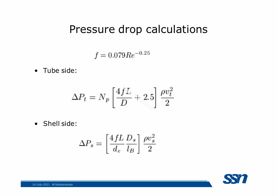
Pressure drop calculations
• Tube side:
• Shell side:
14-July-2011 M Subramanian
www.msubbu.in
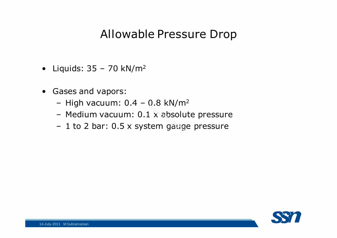
Allowable Pressure Drop
• Liquids: 35 – 70 kN/m2
• Gases and vapors:
– High vacuum: 0.4 – 0.8 kN/m2
– Medium vacuum: 0.1 x absolute pressure
– 1 to 2 bar: 0.5 x system gauge pressure
14-July-2011 M Subramanian
www.msubbu.in
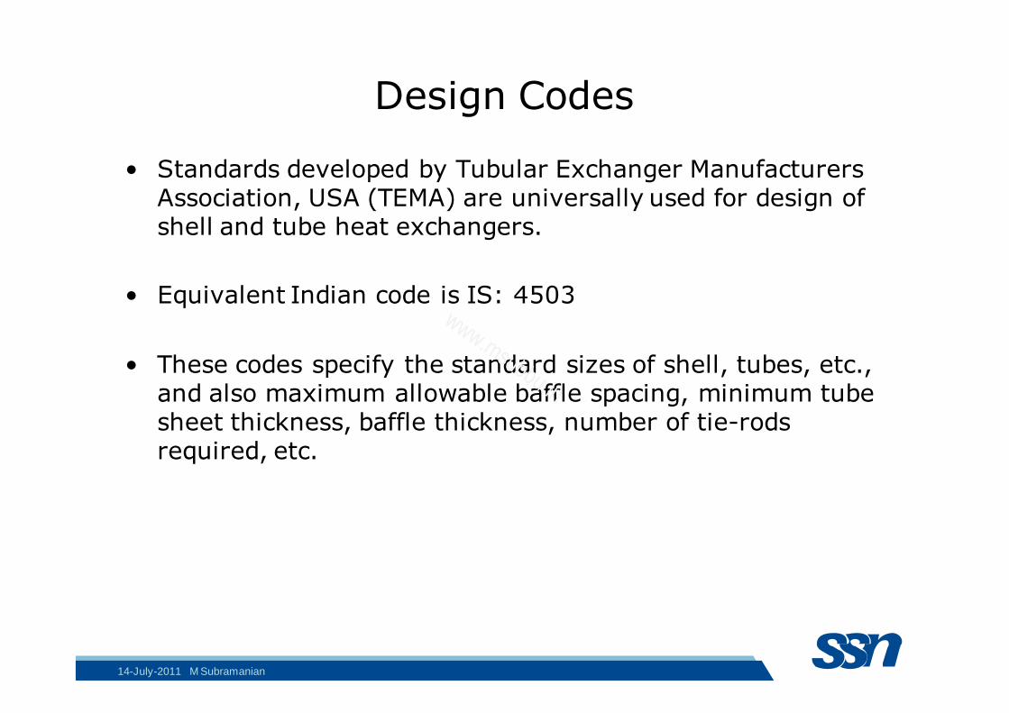
Design Codes
• Standards developed by Tubular Exchanger Manufacturers Association, USA (TEMA) are universally used for design of shell and tube heat exchangers.
• Equivalent Indian code is IS: 4503
• These codes specify the standard sizes of shell, tubes, etc., and also maximum allowable baffle spacing, minimum tube sheet thickness, baffle thickness, number of tie-rods required, etc.
14-July-2011 M Subramanian
www.msubbu.in
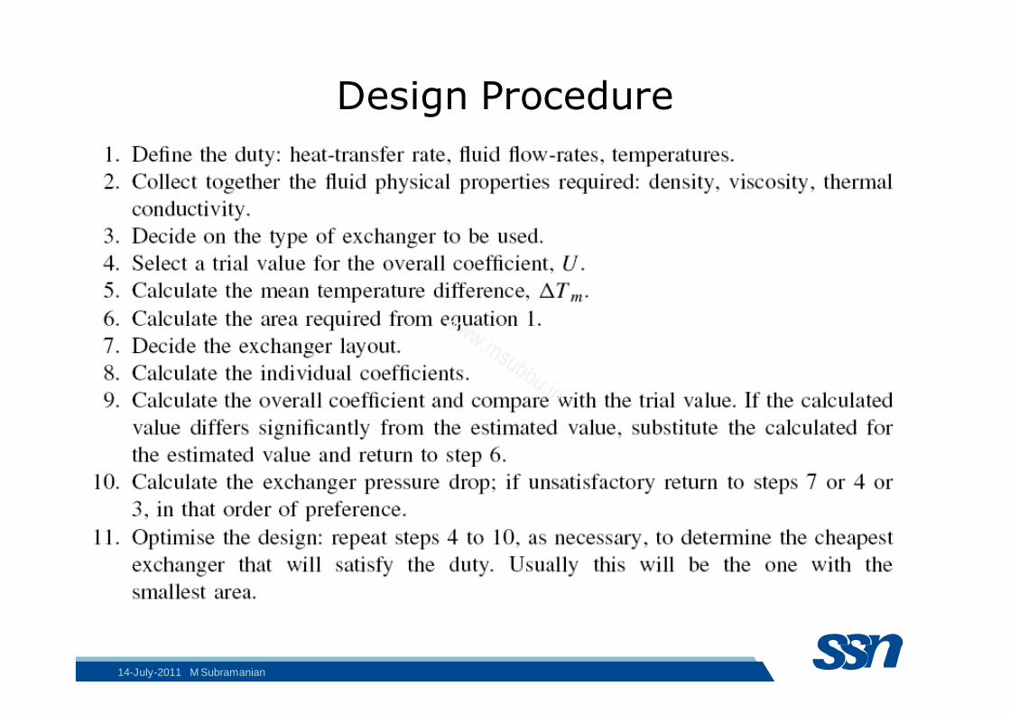
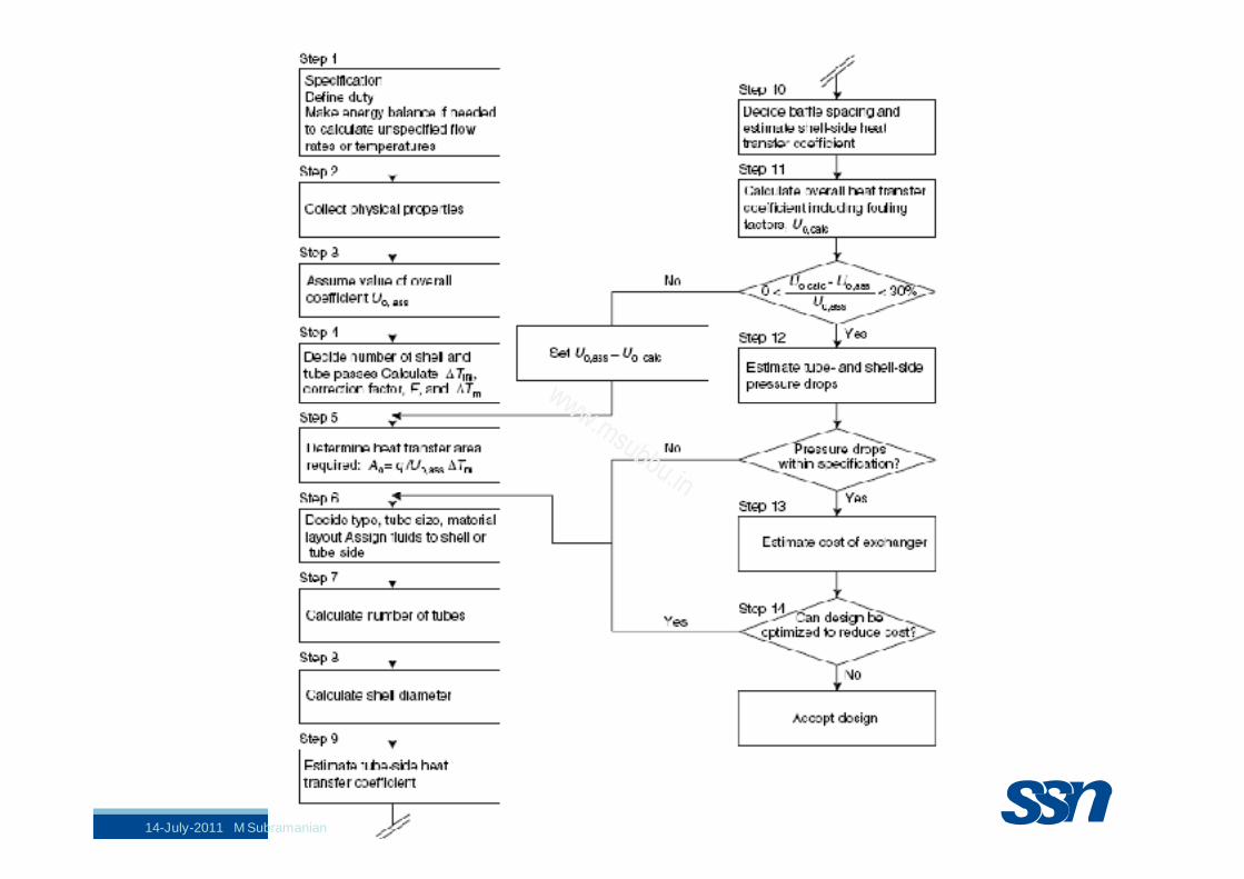
Design Procedure
14-July-2011 M Subramanian
www.msubbu.in
14-July-2011 M Subramanian
www.msubbu.in
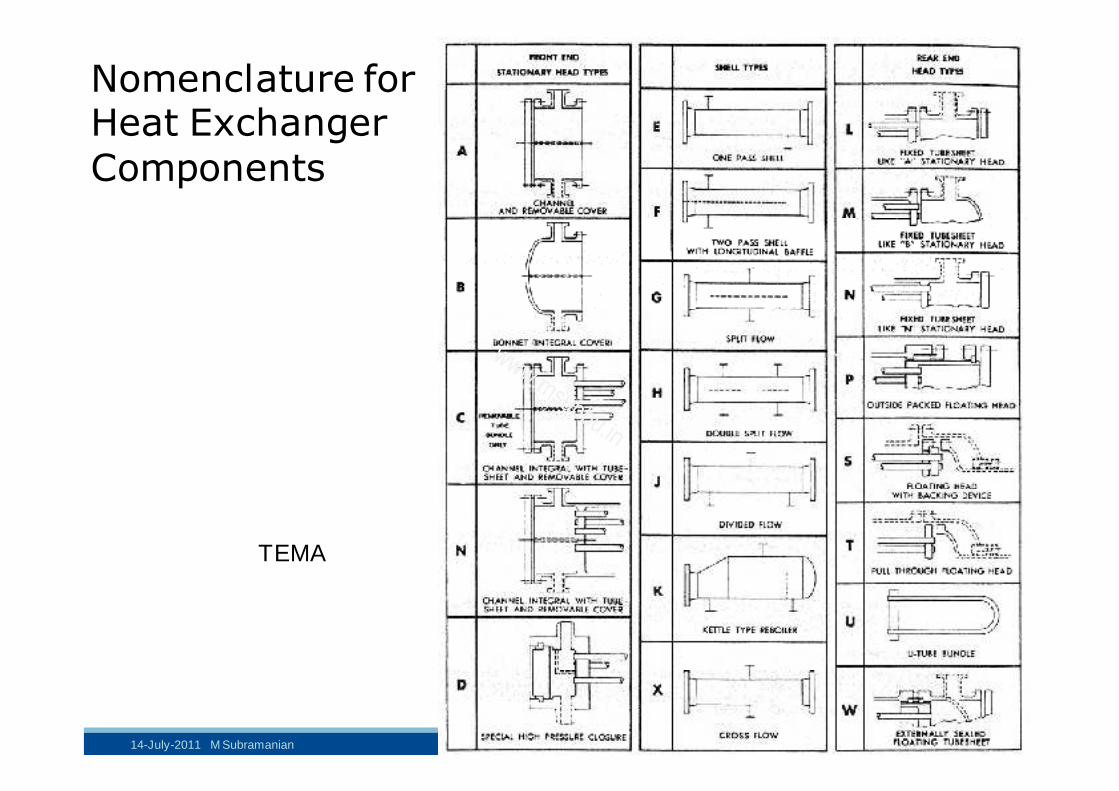
Nomenclature for Heat Exchanger
Components
TEMA
14-July-2011 M Subramanian
www.msubbu.in

14-July-2011 M Subramanian
www.msubbu.in
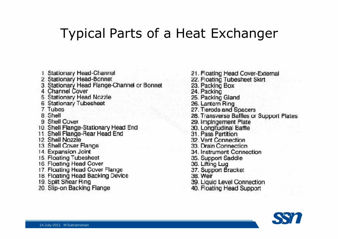
Typical Parts of a Heat Exchanger
14-July-2011 M Subramanian
www.msubbu.in

14-July-2011 M Subramanian
www.msubbu.in